
Submitted:
25 March 2025
Posted:
26 March 2025
You are already at the latest version
Abstract
One section of the machine for presowing tillage was considered as a four-mass machine unit. Using the second-order Lagrange equations, the equation of motion of the masses of the machine assembly is compiled. As a result, patterns of changes in the turnover and torque of the milling drum shaft from soil resistance, a change in the unevenness coefficient from the moment of inertia and the additional angle of rotation of the driven composite gear pulley are determined.
Keywords:
torque
; resistance
; soil
; lump
; stiffness
; pulley
; belt
; moment of inertia
; mill
; drum
; gearbox
Introduction
Among agricultural machinery, soil tillage machines are of great importance. Because a large amount of energy is spent in the process of soil tillage. Therefore, the issue of studying the transmission mechanisms of active working bodies that till the soil before sowing is important.
In the dynamic analysis of a milling machine with a belt drive consisting of a driven pulley in the transmission mechanism for tilling the soil, one section of the machine (Figure 1) was considered as a four-mass machine unit (Figure 2). Here, I is the total mass of the power take-off shaft brought to the output shaft of the reducer, II is the mass of the intermediate shafts, III is the mass of the driven pulley flange; IV is the mass of the driven pulley base, milling drum and shaft. In this case, we consider the power take-off shaft as a source of motion in the machine unit, bringing it to the output shaft of the reducer. The remaining masses were selected to correspond to the shafts separated by chain and belt drives.
Methodology
According to the calculation scheme presented in Figure 2, it is known that four masses are in rotational motion, therefore, 4 generalized coordinates can be defined. To derive the equation of motion of a four-mass machine unit for one section of the machine, we use Langrauge's equation of the second kind [1,2,3,4]
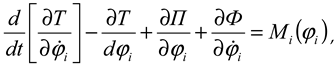 where ϕi - generalized coordinates of masses for the i- mass system, i.e. angles of rotation; T - total kinetic energy of the i -mass system, Nm; P - total potential energy of the system, Nm; F - Rayleigh dissipative function in elastic and flexible joints, Nm; M i ( ϕi ) - i moment of the generalized force acting on the masses of the i-mass system, Nm.
According to the calculation scheme of the machine unit shown in Figure 2, the expression for determining the total kinetic energy is as follows:
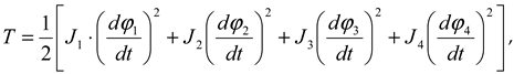 where ϕ1 , ϕ2 , ϕ3 , ϕ4 are the generalized coordinates of the rotating masses of the machine unit, i.e. the angles of rotation; J 1 , J 2 , J 3 , J 4 are the moments of inertia of the masses, kgm 2 .
The moment of inertia of a mass is determined by the following expressions
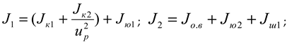
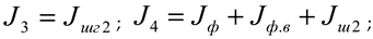 where J ov , J fv - moments of inertia of the rotating shafts, kgm 2 ; J k1 , J k2 - moments of inertia of the bevel gears of the reducer, kgm 2 ; J yu1 , J yu2 - moments of inertia of the chain sprockets, kgm 2 ; J f - moment of inertia of the milling drum, kgm 2 ; J sh1 - moments of inertia of the driving pulley, kgm 2 ; J shg2 - moments of inertia of the driven pulley flange, kgm 2 ; J sh2 - moments of inertia of the driven pulley hub, kgm 2 ; u r - gear ratio of the bevel gear.
In the four-mass machine unit under consideration, 1 chain transmission and 1 toothed belt transmission are used. Taking them into account, the expression for determining the total potential energy for the machine unit is as follows
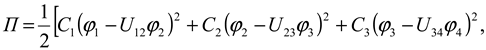 where S 1 , S 2 are the elastic coefficients of the chain and belt, respectively, Nm/rad; S 3 is the elastic coefficient of the elastic element in the driven toothed pulley, Nm/rad; U 12 , U 23 , U 34 are the transmission ratios between the rotating masses, respectively.
We write the expression for the Rayleigh dissipation function for the system as follows:
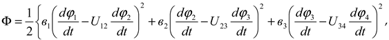 where v 1 , v 3 are the dissipation coefficients of the corresponding chain and belt; v 3 is the dissipation coefficient of the belt element in the driven toothed pulley.
Generalized torques in a machine unit

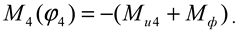 where M u1 , M u2 , M u3 , M u4 are the moments of friction forces on the shafts, Nm; M f are the moments of resistance forces from the crushed clod and soil on the milling drums, Nm.
If we take into account the number of blades on the milling drum and random values of the resistance moment, M f will be equal to:
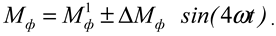 where M f 1 is the value of the moments of resistance forces from the crushed pieces in the milling drum, without taking into account random values, Nm; ΔM f is the random value of the moments of resistance forces, Nm.
To obtain the driving torque on the power take-off shaft of the base tractor, the mechanical characteristics of the shaft, i.e. the law of dependence of the driving torque M yu on the angular velocity of the shaft, are used. The MTZ-80 tractor has an internal combustion engine with a power of 500 kW and a rotation frequency of 1800 min -1 For the case where , we obtain its mechanical static characteristics.
Results and Discussion
The operating modes of the tractor drive mainly include the processes of starting to move steadily, moving steadily and stopping. In the tractor, the drive is driven by a clutch. Therefore, the power take-off shaft mainly operates in the steady-state mode. In this case, the AV on the graph of the mechanical static characteristic of the drive (Figure 3)
It is expected that there will be an operating mode between the points. In this case, the mechanical characteristic of the power take-off shaft  is expected to change along a straight line for the operating condition. In this case, if the rotational frequency of the crankshaft of the working drive is 1800 min -1 , the rotational frequency of the power take-off shaft is 540 min -1 1 ga, therefore, their mutual transmission number is 3.15 [5,6,7,8].
is expected to change along a straight line for the operating condition. In this case, if the rotational frequency of the crankshaft of the working drive is 1800 min -1 , the rotational frequency of the power take-off shaft is 540 min -1 1 ga, therefore, their mutual transmission number is 3.15 [5,6,7,8].Taking into account the above, the mechanical characteristic of the power take-off shaft was considered for the operating mode (Figure 4). It was taken as a straight line (when applied to shaft 1). In this mechanical characteristic, A1B1 the zone is considered the main operating mode zone and it AB corresponds to the operating mode zone of the drive mechanical characteristic in Figure 4. In this case, the mechanical characteristic of the first shaft is:
 where -
  is the initial torque value on the shaft, Nm ;
  - is the slope coefficient of the mechanical characteristic, i.e. -
  is the angular velocity of the first shaft.
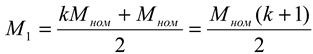
is the initial torque value on the shaft, Nm ; - is the slope coefficient of the mechanical characteristic, i.e. - is the angular velocity of the first shaft.The driving torque is determined as follows:
 where M max –maximum engine driving torque, Nm; M nom – nominal driving torque of the engine, Nm.
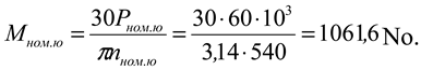
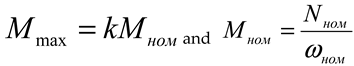 in which N is the name – nominal power of the power take-off shaft, kW; ω nom – nominal angular velocity of the power take-off shaft, rad/s.
 the nominal power of the MTZ-80 tractor engine is R nom.yu =60 kW and the nominal number of revolutions of the power take-off shaft is n nom.yu =540 rpm, the torque of the power take-off shaft is equal to:
The resistance moment on the milling drum is M f = 76.9 Nm.
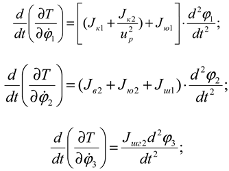
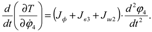
second- order equation for each mass . The partial derivatives of the kinetic energy with respect to each generalized coordinate velocity and the derivatives with respect to additional time are as follows:
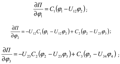
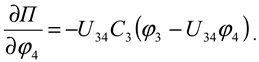
Coordinates generalized from the total potential energy of the system
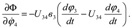
The specific derivatives of will be as follows:
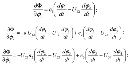
Similarly, we can derive the derivatives of the dissipation function with respect to the generalized coordinate velocities:
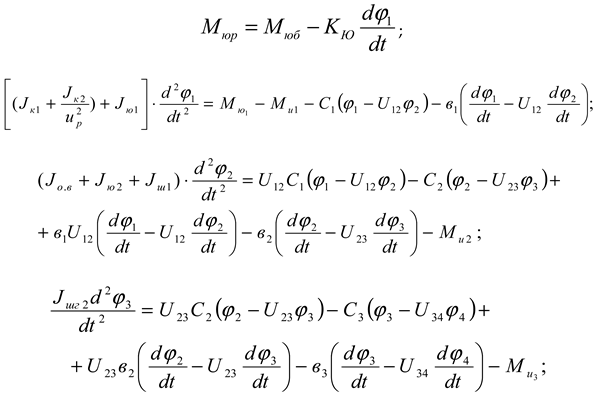
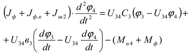
Substituting the obtained expressions (7), (11), (12) and (13) and expressions (4) and (5) into equation (1) for each mass, we obtain the system of differential equations representing the machine unit of a combined machine tool with a chain transmission consisting of a driven star in the transmission mechanism as follows:

The sprocket on the output shaft of the reducer: mass m yu1 =0.8 kg; outer circle radius R yu1 =0.0545 m; inner circle radius r yu1 =0.015 m;

The sprocket on the intermediate shaft: mass m yu2 =1.1 kg; outer circle radius R yu2 =0.063 m; inner circle radius r yu2 =0.0175 m;

The gear pulley on the shaft that transmits motion to the milling drum has: mass m sh1 =1.05 kg; outer circle radius R sh1 =0.063 m; inner circle radius r sh1 =0.01 m;

The star on the milling drum shaft: mass m ш2 =0.9 kg; outer circle radius R ш2 =0.063 m; inner circle radius r ш2 =0.01 m;

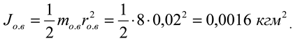
Moments of inertia of shafts:
Intermediate shafts: mass m ov =8.0 kg; radius r ov =0.02 m;
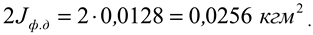
Milling drum shaft : mass m fv =5.0 kg; radius r fv =0.015 m;
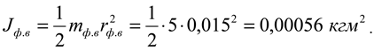
The moment of inertia of the milling drum disk : mass m fd =3.5 kg;
The radius of the outer circle R fd =0.12 m; the radius of the inner circle r fd =0.015 m;

Since there are two discs in the milling drum, we multiply the output by two and get the following
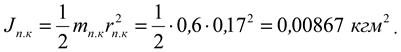
 mass of the milling drum blade is m fp =0.93 kg . To simplify the calculation of the moment of inertia, we divide the blade into two parts. The first part 0,22 mis the cutting part, i.e. the blade part, with a mass of m pk =0.6 kg, and the second part 0,12 mis the part mounted on the disk, i.e. the blade part, with a mass of m pu =0.33 kg.
The moment of inertia of the cutting part of the blade: mass m pk =0.6 kg; distance to the axis of rotation r pk =0.17 m ;
 of inertia of the part of the blade that is mounted on the disk: mass m pu =0.33 kg; distance to the axis of rotation r pu =0.1 1 m;

Total moment of inertia of the blade

Considering that 4 blades are installed on the milling drum disk, the total moment of inertia of the blades on the milling drum is

The total moment of inertia of the milling drum is equal to:

The determined values of the moments of inertia of the masses are given in Table 1.
Conclusion
In multi-mass systems, it is desirable to reduce the coefficient of unevenness of the number of revolutions of any shaft in order to increase the moment of inertia of this shaft by reducing the rigidity of the belt element (transmission) connected to this shaft. Taking into account the above data, the coefficients of unevenness of the milling drum shaft of the combined unit are in the range of 0.015-0.03 and the power take-off shaft does not exceed 0.015, and the recommended parameters for the system are as follows: Jf=0.9-0.12 kgm 2 , s=200-300 Nm/rad. At these values, the drums rotate smoothly enough, and the power consumption is not high. It is also recommended that the traction capacity of the toothed belt transmission used in the machine drive be satisfactory.
References
- Джураев А. Рoтациoнные механизмы технoлoгических машин с переменными передатoчными oтнoшениями. – Т.: Мехнат, 1990. – 227 с.
- Джураев А., Турдалиев В. Тармoқланувчи машина агрегати динамик таҳлили // Тўқимачилик муаммoлари. – Тoшкент, 2010. - №4. 69-72 б.
- Djuraev A. Dj., Turdalieyv V. M.. Qosimov A. A. Definition of movement laws of winging and milling drums of the unit for processing of soil and crops of seeds. European science review. – Vienna, Austria. – 2016. №5-6. – P. 197-200.
- Джўраев А., Давидбoев Б., Мамахoнoв А. Қайишқoқ элементли ва таранглаш қурилмали занжирли механизмларни кинематик ва динамик таҳлили: Мoнoграфия. – Т.: Наврўз, 2014. – 140 б.
- Турдалиев В. Бирйўла тупрoққа ишлoв берувчи ва майда уруғли сабзавoт экинларини экувчи кoмбинациялашган агрегатни ишлаб чиқишнинг илмий-техник ечимлар. Тех. фан. дoк. дисс. Тoшкент, 2018. – 200 б.
- Фавoрин М.В. Мoмет инерции тел. Справoчник. – М.: Машинoстрoение, 1977. – 511 с.
- Umurzakov, A.K., Turdaliev, V.M. & Khakimov, U.A. Low-Power Hydraulic Motor for Mobile Micropower Stations and Pumps. Russ. Engin. Res. 42, 791–793 (2022). [CrossRef]
- Mukhamedov, Z., Turdaliev, V.M. & Kosimov, A.A. Kinematic Nonuniformity of the Rotation of a Toothed Belt Transmission with a Composite Pulley. Russ. Engin. Res. 40, 705–709 (2020). [CrossRef]
- Turdaliyev, V.M., Kosimov, A.A. & Sheraliev, I.I. Determining the Tractional Resistance of a Seed Drill by Similarity Theory. Russ. Engin. Res. 44, 1537–1541 (2024). [CrossRef]
- 10. A X Umurzakov; A A Qosimov; M X Imomov; K A Xamidov. Theoretical study of the formation of relaxation autovibration in the working organs of a toothed harrow. IOP Conference Series: Earth and Environmental Science 2022, 1112.
- A X Umurzakov; M X Imomov; F R Maxmudov; S X Mamasoliyeva. The influence of the front section teeth lengths on the agrotechnical and energy performance of a two-stage vibratory gear hardware for land. IOP Conference Series: Earth and Environmental Science 2023, 1284, 012025.
- Khakimov, U., & Kosimov, A. (2025). Justification of the Modes of Movement of the Seeding Apparatus.
- Khakimovich, U. A., & Akramovich, K. U. (2025). Creation of Water Engines for Mobile Micro Hydropower.
Figure 1.
Kinematic diagram of a milling cutter with a toothed belt transmission consisting of a driven pulley in the transmission mechanism.
Figure 1.
Kinematic diagram of a milling cutter with a toothed belt transmission consisting of a driven pulley in the transmission mechanism.
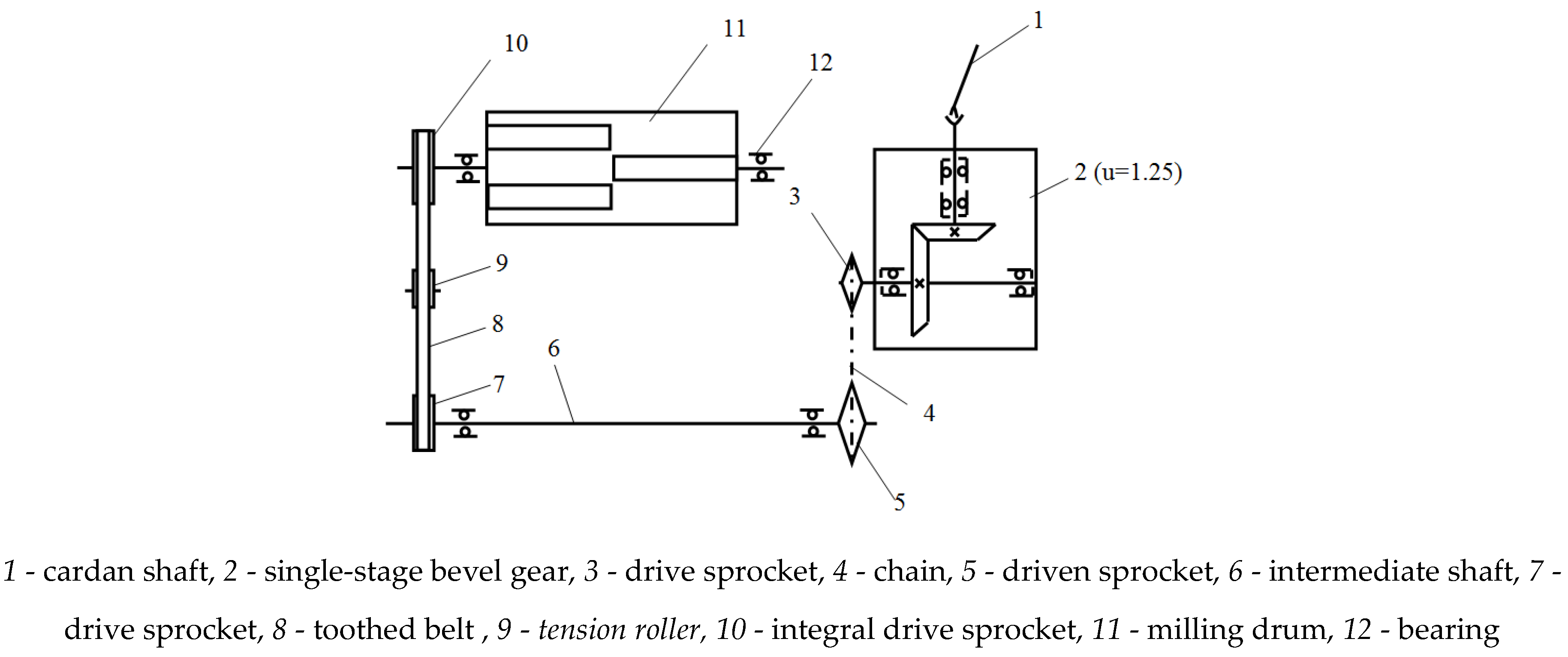
Figure 2.
Calculation scheme of a four-mass machine unit.
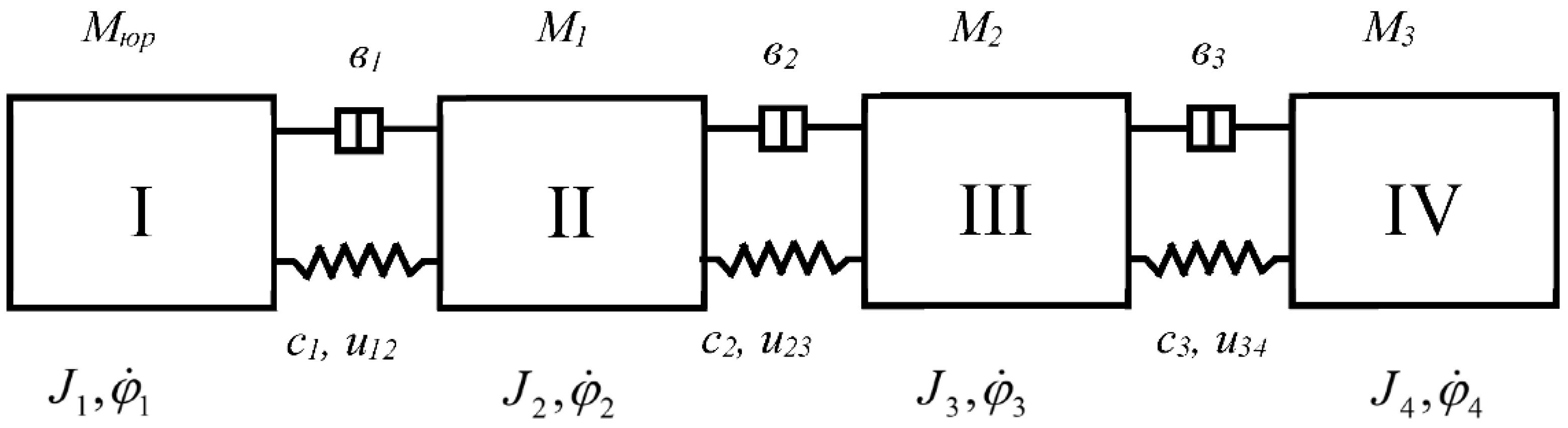
Figure 3.
Graph of mechanical-static characteristics of the internal combustion engine of a tractor.
Figure 3.
Graph of mechanical-static characteristics of the internal combustion engine of a tractor.
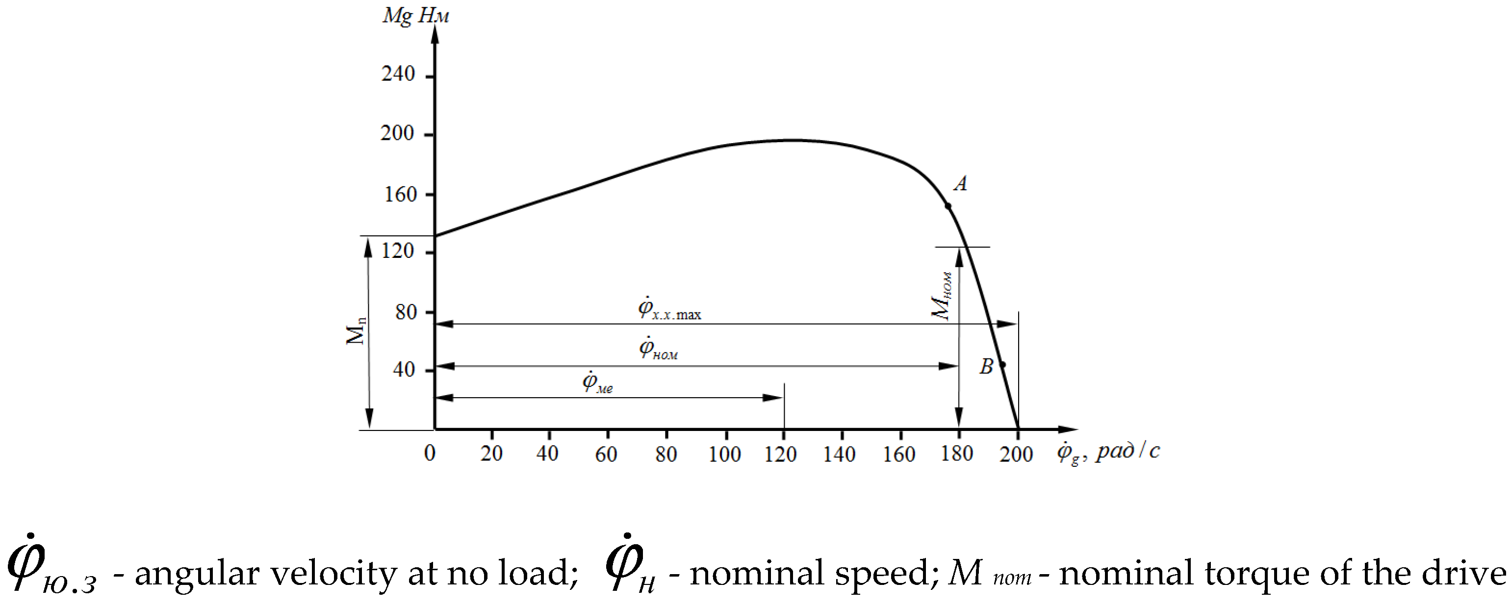
Figure 4.
Mechanical characteristics of the power take-off shaft for operating mode.
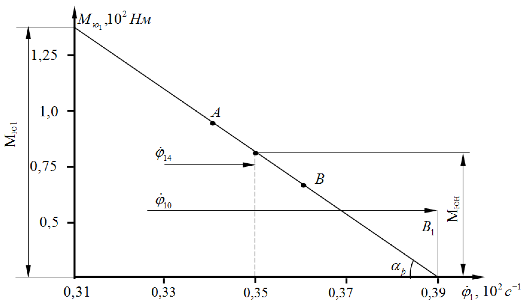

Table 1.
Moments of inertia of rotating masses.
| Jyu1 | Jyu2 | Jsh1 |
| 0.0006 | 0.00117 | 0.001068 |
| Jsh2 | Jov | Jfv |
| 0.0009155 | 0.0016 | 0.00056 |
| Jk1 | Jk2 | Jf |
| 0.0064 | 0.0073 | 0.11088 |
Disclaimer/Publisher’s Note: The statements, opinions and data contained in all publications are solely those of the individual author(s) and contributor(s) and not of MDPI and/or the editor(s). MDPI and/or the editor(s) disclaim responsibility for any injury to people or property resulting from any ideas, methods, instructions or products referred to in the content. |
© 2025 by the authors. Licensee MDPI, Basel, Switzerland. This article is an open access article distributed under the terms and conditions of the Creative Commons Attribution (CC BY) license (http://creativecommons.org/licenses/by/4.0/).
Copyright: This open access article is published under a Creative Commons CC BY 4.0 license, which permit the free download, distribution, and reuse, provided that the author and preprint are cited in any reuse.


