

Submitted:
06 March 2025
Posted:
09 March 2025
You are already at the latest version
Abstract
The carbon footprint associated with human activity, particularly from energy-intensive industries such as iron & steel, aluminum, cement, oil & gas, and petrochemicals, contributes significantly to global warming. These industries face unique challenges in achieving Industry 4.0 goals due to the widespread adoption of industrial Internet of Things (IIoT) technologies, which require reliable and efficient power solutions. Conventional wireless devices powered by lithium batteries have limitations, including reduced lifespan in high-temperature environments, incompatibility with explosive atmospheres, and high maintenance costs. This paper proposes a novel approach to address these challenges by leveraging residual heat to power IIoT devices, eliminating the need for batteries and enabling autonomous operation. Based on the Seebeck effect, thermoelectric energy harvesters transduce waste heat from industrial surfaces, such as pipes or chimneys, into sufficient electrical energy to power IoT nodes for applications like condition monitoring and predictive maintenance of rotating machinery. The methodology presented standardizes the modelling and simulation of waste heat recovery systems (IoT-WHRS), demonstrating their feasibility through statistical analysis of IoT-WHRS architectures. Furthermore, this technology has been successfully implemented in a petroleum refinery, where it benefits from the NB-IoT standard for long-range, robust, and secure communications, ensuring reliable data transmission in harsh industrial environments. The results highlight the potential of this solution to reduce costs, improve safety, and enhance efficiency in demanding industrial applications, making it a valuable tool for the energy transition.
Keywords:
1. Introduction
2. Industrial IoT Application for Predictive Maintenance
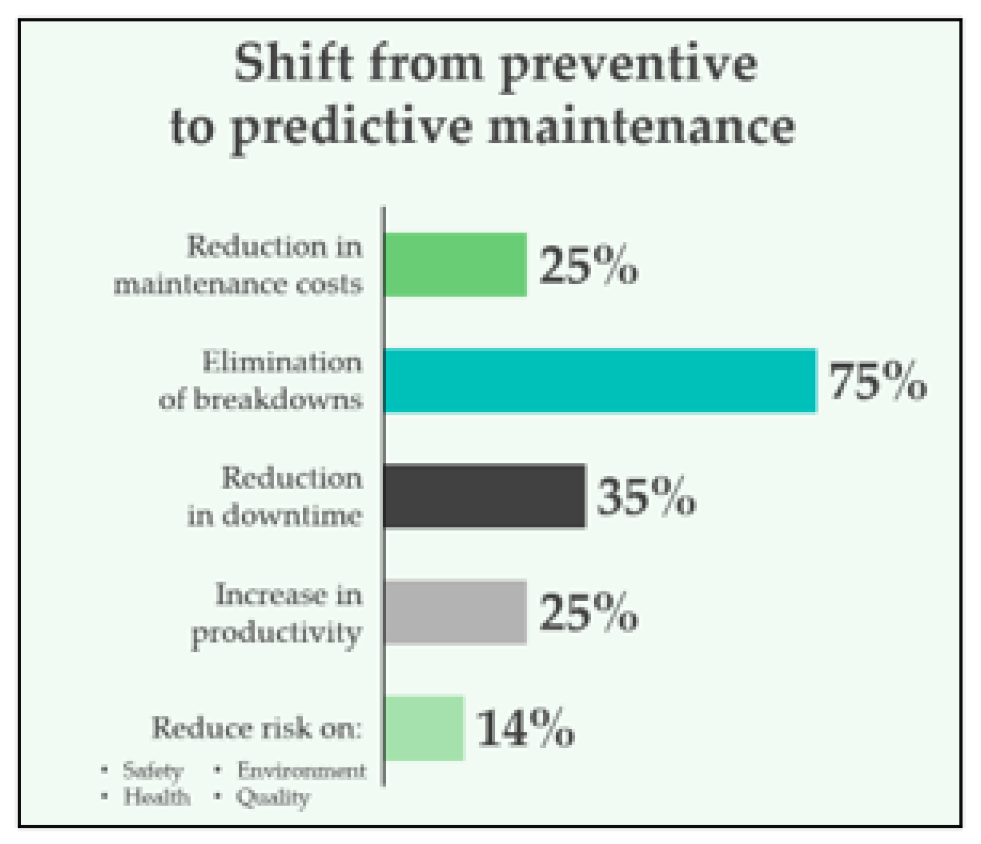
2.1. Main Benefits
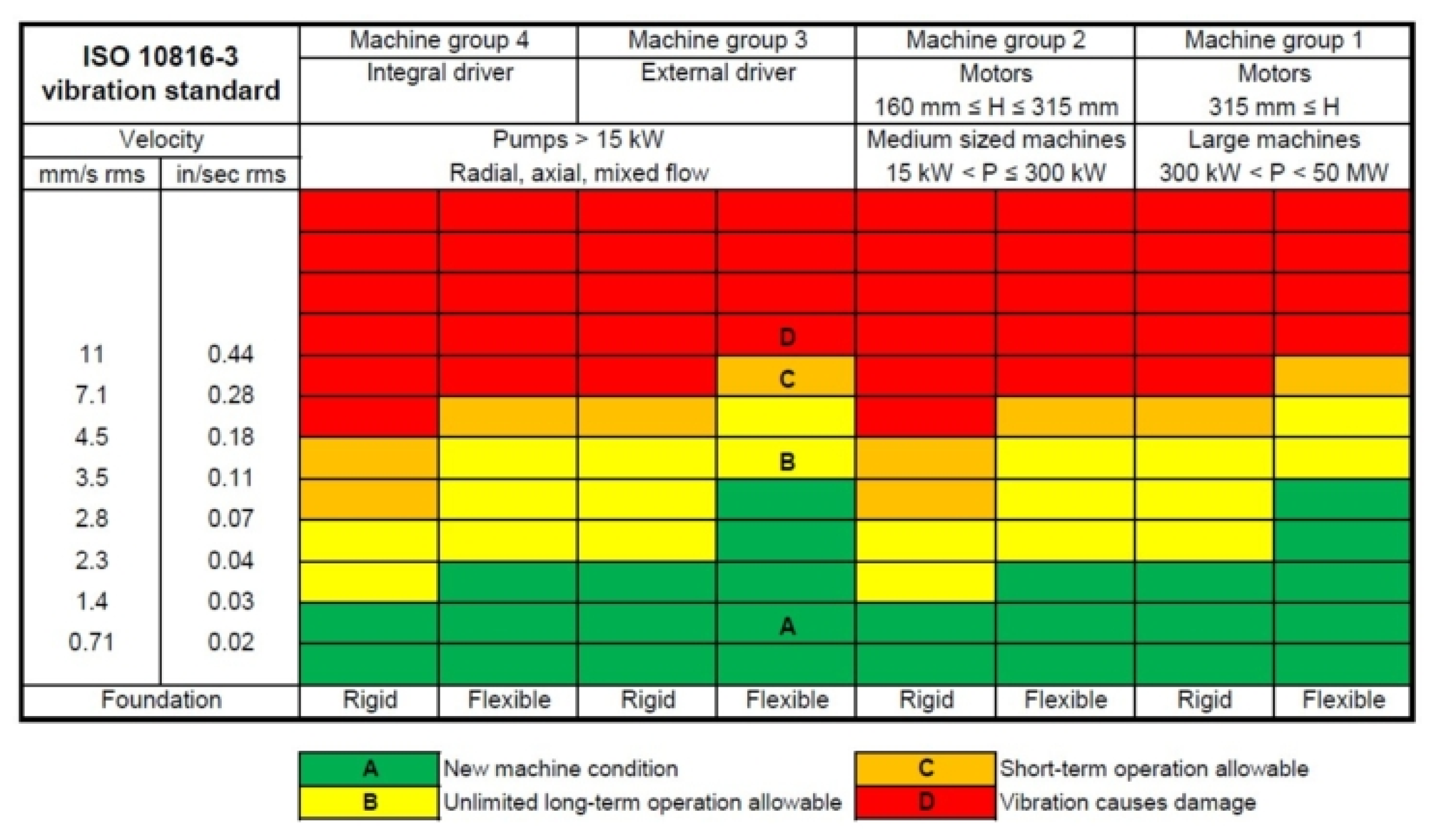
2.2. Velocity Measurement
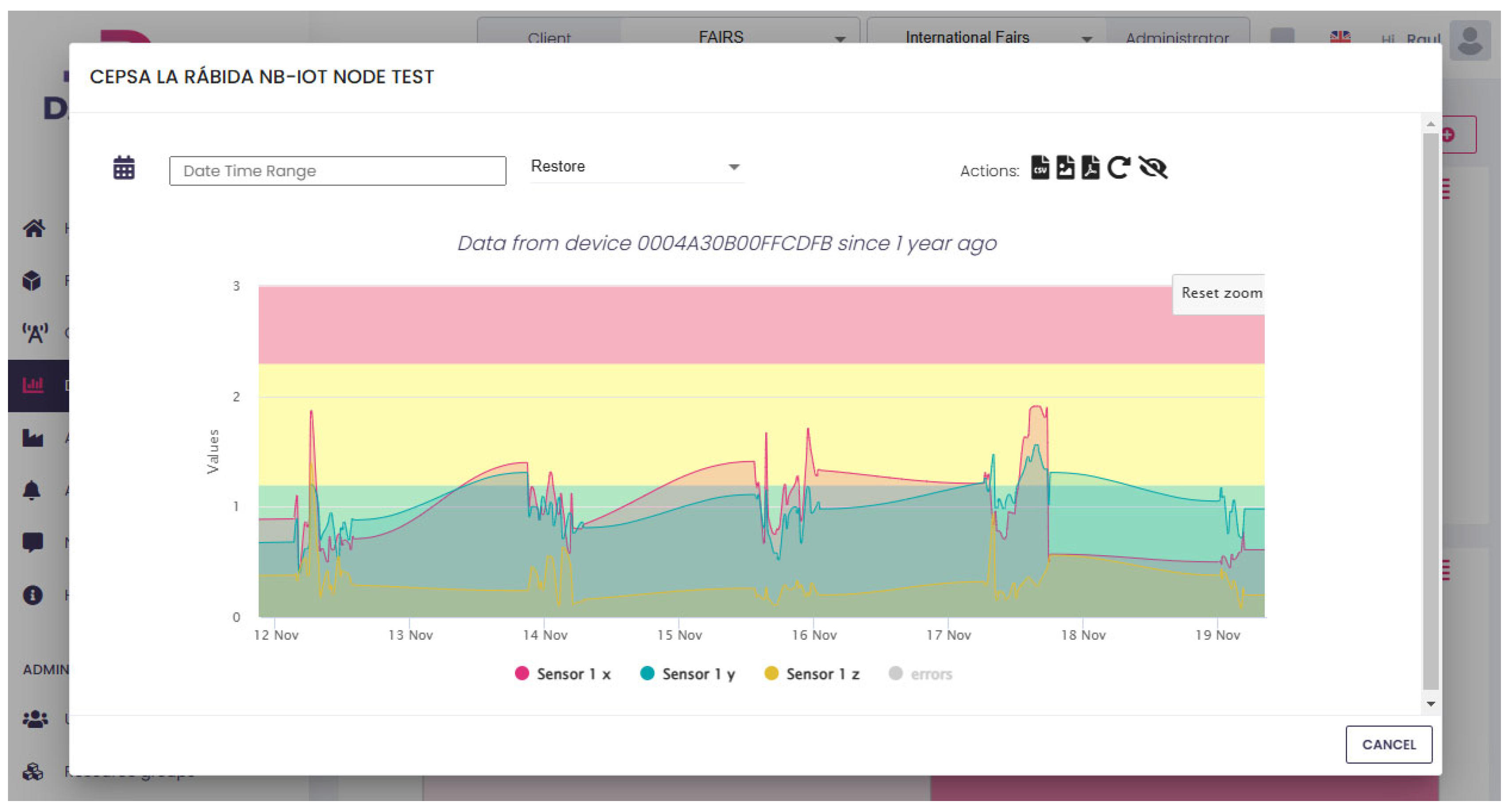
- Green Zone: Normal operation, no intervention needed.
- Yellow Zone: Warning level, maintenance should be scheduled.
- Red Zone: Critical level, immediate action required to prevent failure.
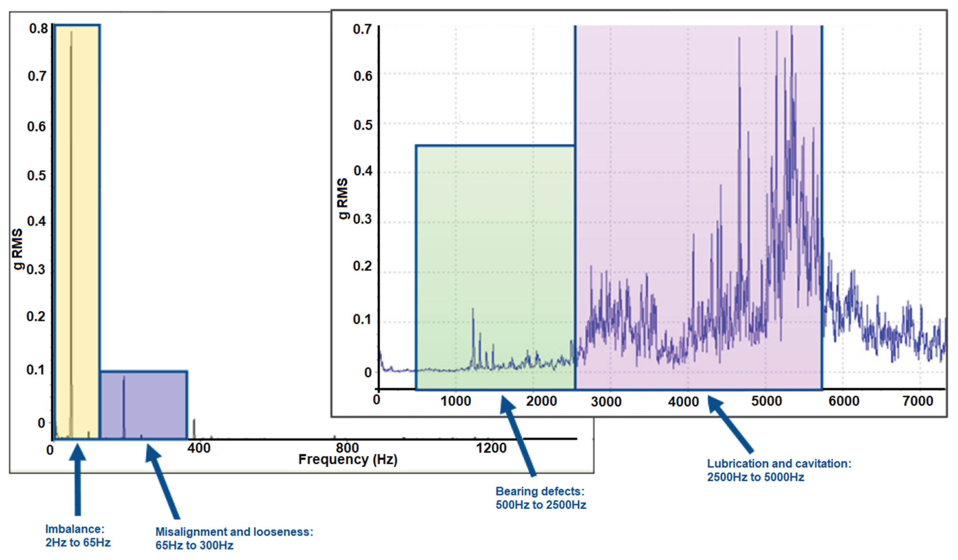
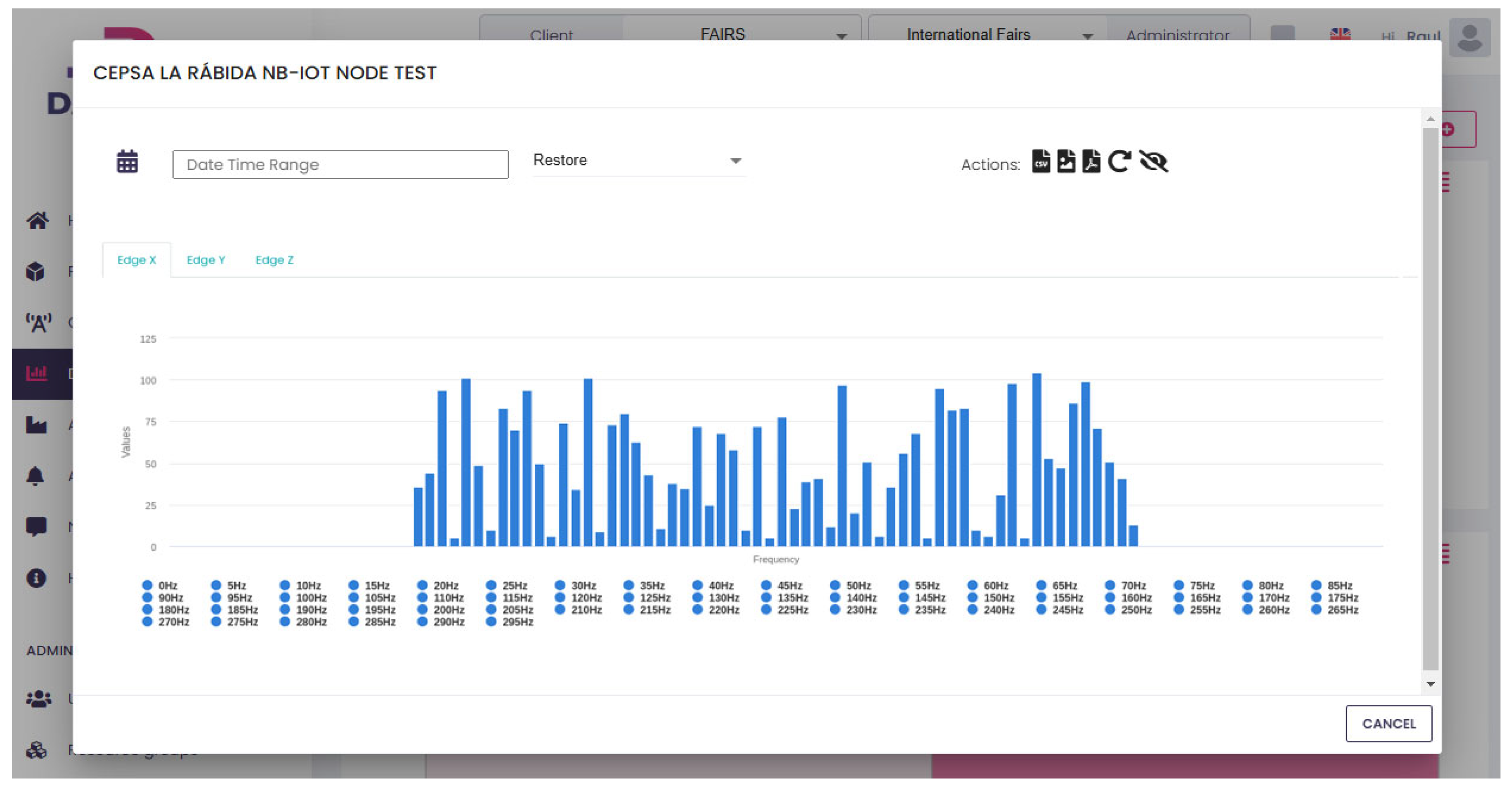
- Imbalance: Detected at the rotational frequency of the motor (1× RPM or the fundamental frequency, typically from 2Ht to 65Hz).
- Misalignment: Typically appears at 1× RPM and higher harmonics (e.g., 2× RPM, 3× RPM typically from 65Hz to 300Hz).
- Bearing faults: Characterized by specific frequencies such as the Ball Pass Frequency Outer (BPFO), Ball Pass Frequency Inner (BPFI), or fundamental train frequency (FTF), which depend on the bearing geometry and rotational speed, typically from 500Hz to 2500Hz.
- Lubrication and cavitation issues: Detects lack of lubrication in the gearboxes as well as air bubbles in the lubrication, typically from 2500Hz to 5000Hz.
3. Heat-Powered IIoT Architecture
3.2. IoT-WHRS Model Parametrization
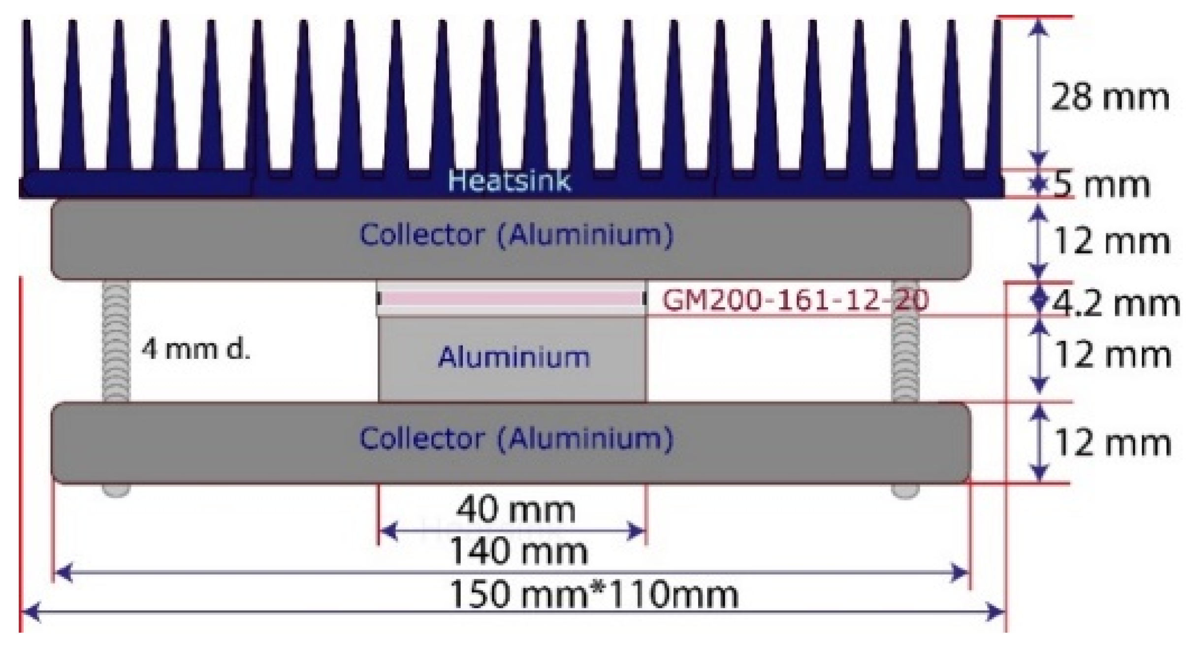
- A GM200-161-12-20 Peltier cell acting as the TEG.
- An aluminium plate serves as the heat transmitter between the aluminium collector and the TEG.
- Finally, the system is fastened between two pieces of aluminium Al6063-T5, corresponding to the collector and the base of the heatsink, which is attached to an Al6063-T5 heatsink base. This optimized design allows the IoT-WHRS to harness energy efficiently from waste heat.
- Thermal Properties of Materials: Materials like copper, aluminium alloys (Al6063-T5), alumina, graphite, and mica contribute differently to heat transfer. Copper offers the highest thermal conductivity, while air is modelled as an ideal gas due to its low density.
- Contact Resistance: Microhardness and surface roughness influence the contact resistance between materials, affecting heat transfer efficiency [18]. Air gaps caused by surface irregularities can increase resistance, reducing performance.
- TEG Model: The TEG's performance is modelled using an "effective parameter model" due to limited manufacturer specifications, incorporating properties of its pellets, ceramics, and welds.
- Heatsink Efficiency: The heatsink’s fins dissipate heat to the environment, while the base transfers heat from the TEG. The material and geometry of the fins are crucial for cooling performance [19].

| Units | Air (*) | Al6063-T5 | Graphite | |
| Density | ρ, (Kg/m3) | 1.1839 | 2700 | 1800 |
| Thermal conductivity | K, (W/(mK)) | 0.0261 | 209 | 5 |
| Specific heat | Cp, (J/(kgK)) | 1,004.3 | 896 | 895 |
| Micro-hardness (**) | μH, (MPa) | 670 | 100 | |
| Surface roughness (**) | sR, (μm) | 1.8 | 2.0 |
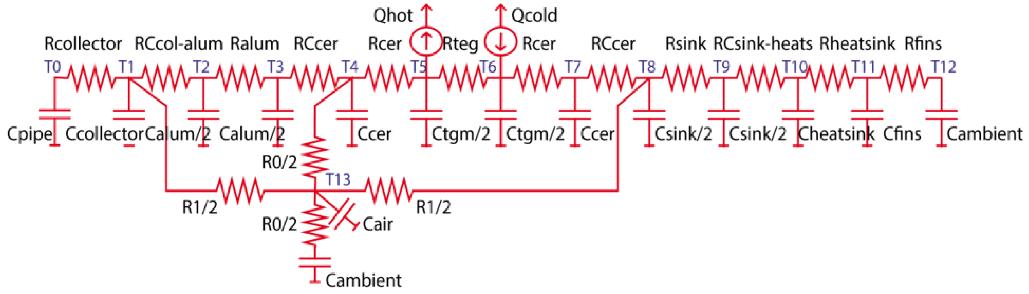
- Collector and heatsinks: Constructed from aluminum to optimize heat conduction.
- Thermoelectric generator (TEG): Encompasses the thermoelectric effect, ceramic plates, and welds connecting these plates. Heat rejection and absorption are represented by Qhot and Qcold, respectively.
- Heatsink and its fins: Responsible for dissipating heat into the surrounding environment.
- Contact interfaces: Points of interaction between components introduce thermal resistance that impedes heat transfer.
- Airgap volume: Acts as a thermal barrier, contributing to the overall resistance within the system.
3.3.1. Heat Transfer Contribution Via the TEG ChannelHeat transfer within the TEG channel involves contributions from multiple components. Following the models described in [13], the TEG's thermal behaviour accounts for the resistive and capacitive properties of its thermoelectric pellets represented as Rteg and Cteg. These parameters are temperature-dependent and must be recalculated dynamically during simulations. Surrounding the pellets are ceramic plates (made of alumina), which add their own thermal resistance (Rceramics and heat capacity (Cceramics), derived from the material’s conductivity, heat capacity, and geometry.
3.3.2. Heat Transfer Contribution Via the TEG Channel
- R0: Represents the transverse heat transfer between the TEG and the surrounding environment.
- R1: Models the thermal channel connecting the heatsink and the collector.
- R2: Accounts for heat transfer between the insulator and the collector.
- Cair1 and Cair2: Represent the heat storage capacities of the airgap channels.
3.4. TEG Effective Parameters Model
m01 = -(dt/Cpipe) (1/Rcol)
m10 = -(dt/Ccol) (1/Rcol)
m11 = 1+(dt/Ccol) (1/Rcol+1/Rccolalum+1/Rair1)
m12 = -(dt/Ccol) (1/Rccolalum)
m1d = -(dt/Ccol) (1/Rair1)
…
mba = -(dt/Cfins) (1/Rdis)
mbb = 1+(dt/Cfins) (1/ Rdis +1/Rfins)
mbc = -(dt/ Cfins) (1/Rfins)
mcb = -(dt/Camb) (1/Rfins)
mcc = 1+(dt/Camb) (1/Rfins+1/Rair0)
mcd = -(dt/Camb) (1/Rair0)
4. Edge Computing for Battery-less Device with NB-IoT
4.1. Eliminating Batteries: A New Paradigm for IIoT Monitoring
4.2 Overcoming Technological Barriers for Wireless IIoT
- Efficiency of DC/DC converters.
-
Processor operations, such as:
- ▪
- Operational frequency (MHz).
- ▪
- Power-saving modes (e.g., sleep, ultra-sleep).
- ▪
- Edge-computing algorithms and firmware optimization.
- Sensor power requirements and signal conditioning electronics.
- Wireless communication protocol energy usage.
- Edge-computing capabilities for advanced data processing, including FFT, filtering, and ML / DL algorithms.
- Continuous operation in hazardous environments (ATEX) without requiring battery replacements.
- Data transmission at high throughput rates of up to 256 Kbps.
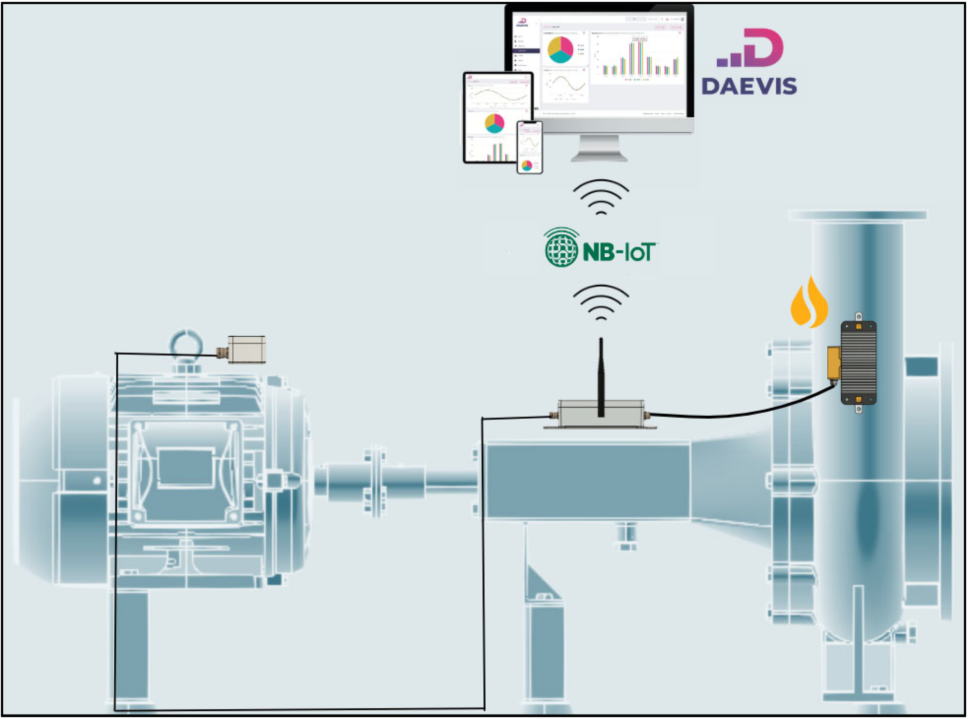
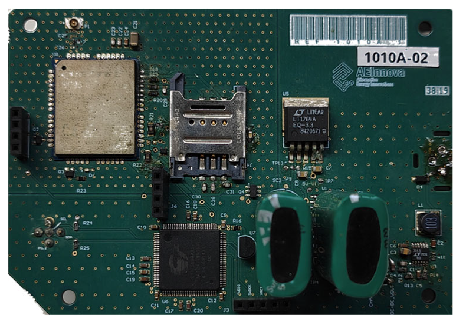
- Communications Hardware: Includes a 5 dBi antenna, the Quectel BG96 NB-IoT UART module, and a SIM card for wireless connectivity (from Vodafone).
- Power Electronics: Comprises a DC/DC converter with MPPT to supply power to the external sensor, an energy buffer for alternative energy sources, energy management circuitry, and an SPI bus interface connected to an internal 3-axis vibration IMU (Inertial Measurement Unit) from STMicroelectronics.
- Programmable Cortex M3 (32-bit processor), integrated Flash and RAM memory, analog and digital FPGA capabilities, and communication interfaces such as digital communication buses.
5. Results
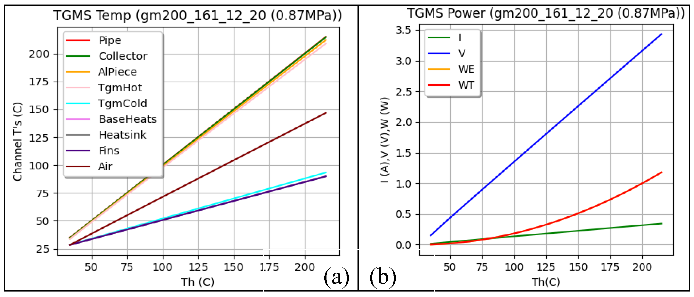
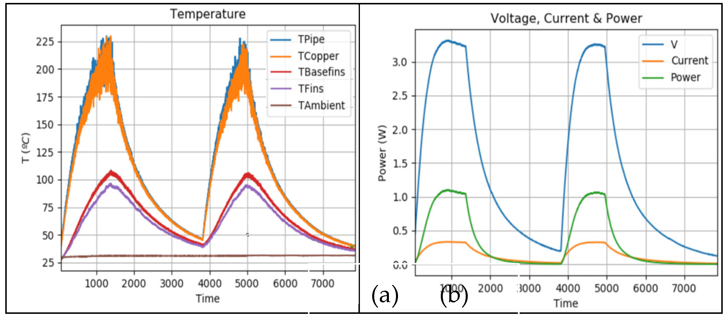
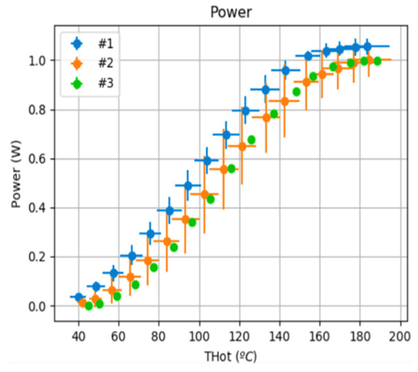
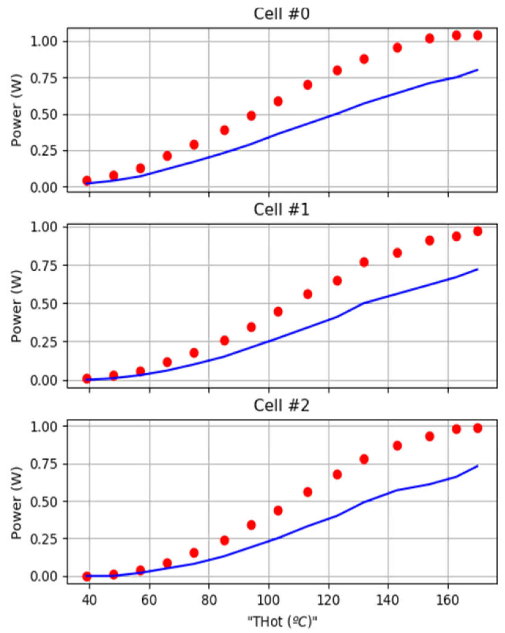
5.1 WHRU Characterization
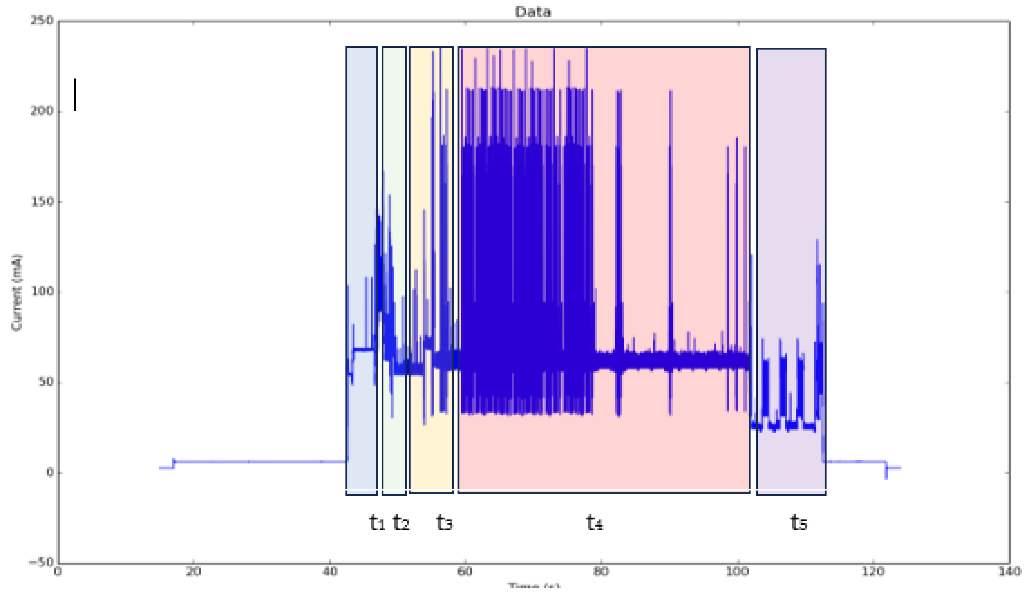
- T1. Wake-up.
- T2. Data acquisition from the 3-axis vibration sensor.
- T3. Data processing (velocity and spectrum).
- T4. NB-IoT link and communication to the network.
- T5. Data storage for postprocessing.
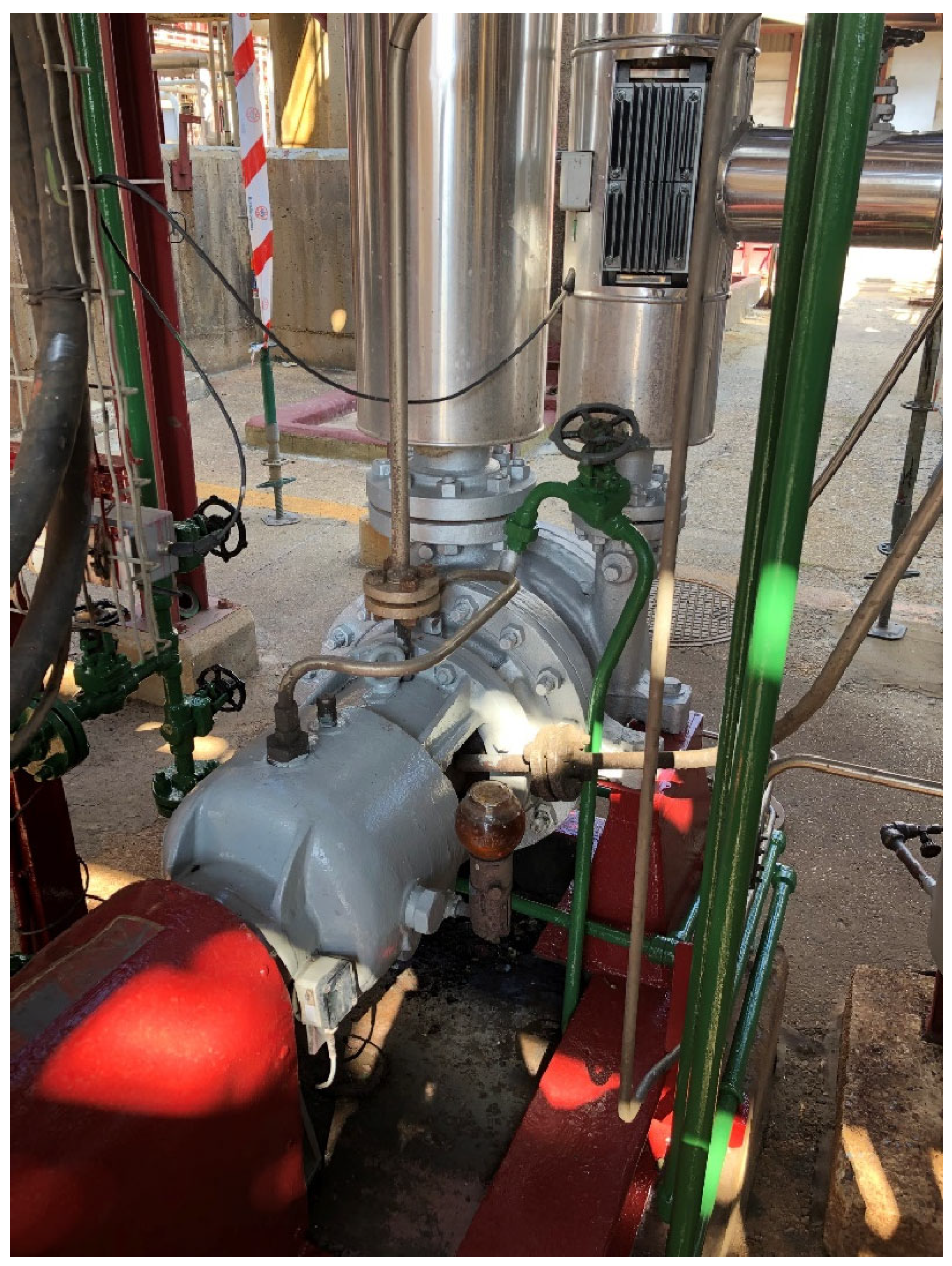
5.3. Pilot Installation in a Hot Water Pump
- Green: Healthy machine: 0 mm/s to 1.2 mm/s
- Yellow: Short-term operation allowable: 1.2 mm/s to 2.3 mm/s
- Red: Machine damage likely: Above 2.3 mm/s
6. Background and Related Work
| roduct / Model | Wireless technology | Energy source | Bandwidth | Nº Axis | Information sent | Data transmit |
| AEInnova Indueye (this paper) | NB-IOT | Waste heat. | 1Hz to 2KHz | 3 |
|
Every 60 seconds up to 1 hour. |
| Everactive / Fluke 3562 [22] | Proprietary Wireless protocol. Up to 1000 nodes and 250m. | Waste Heat or solar | 6Hz a 1KHz | 3 |
|
From 15 seconds to 15 minutes. |
| Emerson AMS [23] | WirelessHART. Up to 100 nodes and 50m. | Battery. Expected 3-5 years in lab conditions. | X, Y 1KHz, Z up to 20KHz | 3 |
|
1 Hour velocity, 1 time per day Spectrum. |
| SKF Vibration Sensor [24] | WirelessHART. Up to 100 nodes and 50m. | Battery. Expected 2-3 years in lab conditions. | 10 Hz a 1KHz | 1 |
Vibration:
|
Temperature every 5 minutes. Vibration every 1 hour. |
| Yokogawa Sushi [25] | LoRaWAN (up to 2Km) | Battery. Expected 2 years. | 10Hz a 1KHz. | 3 | Vibration:
|
1 data per minute up to every 3 days. |
6. Conclusions
Author Contributions
Funding
Data Availability Statement
Acknowledgements
Conflicts of Interest
References
- D. W. Kweku, O. Bismark, A. Maxwell, K. A. Desmond, K. B. Danso, E. A. Oti-Mensah, A. T. Quachie and B. B. Adormaa, ”Greenhouse effect: greenhouse gases and their impact on global warming,” in Journal of Scientific Research & Reports, JSRR.39630, 17(6), pp 1-9, Feb. 2018.
- G. Bianchi, G.P. Panayiotou, L. Aresti, S.A. Kalogirou, G. A. Florides, K. Tsamos, S.A. Tassou and P. Christodoulides., “Estimating the waste heat recovery in the European Union industry,” in Energy, Ecology and Environment, 4(5), pp. 211–221, Elsevier, 2019.
- H. Elahi, K. Munir, M. Eugeni. and S. Atek, P. Gaudenzi, “Energy harvesting towards self-powered IoT devices,” in Energies, 13, 5528, pp 1-31, 2020.
- O.H. Ando Junior, A. L. O. Maran and N. C. Henao, “A review of the development and applications of thermoelectric microgenerators for energy harvesting,” in Renewable and Sustainable Energy Reviews, 91, pp 376-393, 2018.
- S. Patidar, “Applications of thermoelectric energy: a review,” in International Journal for Research in Applied Science & Engineering Technology (IJRASET), Vol 6 no V, pp. 1992-1996, May, 2018.
- H.Jouhara, N. Khordehgah, S. Almahmoud, B. Delpech, A. Chauhan and S.A. Tassou, “Waste heat recovery technologies and applications,” in Thermal Science and Engineering Progress, 6, pp. 268-289, Elsevier, 2018.
- A. Rodríguez, J.G. Vián, D. Astrain and A. Martínez, “Study of thermoelectric systems applied to electric power generation,” in Energy Conversion and Management, 50, pp. 1236–1243, 2009.
- J. Oliver, R. Malet, R. Aragonés, R. Voces and C. Ferrer, “Waste heat recovery unit for energy intensive industries Thermoelectricity Harvesting,” in Proc. IEEE 29th International Symposium on Industrial Electronics (ISIE), Delft, The Netherlands, 2020, 17-19, pp 1041-1046.
- T. Sanislav, G.D. Mois, S. Zeadally, S.C. and Folea, “Energy harvesting techniques for internet of things (IoT),” in IEEE Access, Vol 9, pp. 39530-39549, Mar, 2021.
- S. Zeadally, F. K. Shaikh, A. Talpur and Q. Z. Sheng, "Design architectures for energy harvesting in the Internet of Things," in Renewable and Sustainable Energy Reviews, 128(1), pp 1-22.
- Jamil, N.; Hassan, M.; Lim, S.; Yusoff, A. "Predictive maintenance for rotating machinery by using vibration analysis." Journal of Mechanical Engineering and Sciences, 2021, 15(3), pp. 8289–8299.
- P. Aranguren, M. Araiz., D. Astrain and A. Martinez, “Thermoelectric generators for waste heat harvesting: a computational and experimental approach,” in Energy Conversion and Management, 148, pp. 680–91, 2017.
- S.L.L. Weera. “Analytical performance evaluation of thermoelectric modules using effective material properties”. M.S. Thesis. Western Michigan University. 2014.
- C. Alaoui, “Peltier thermoelectric modules modeling and evaluation,” in Int. Journal of Engineering (IJE), Vol. 5, Issue 1, pp 114-121, 2011.
- M. M. Yovanovich, J. R. Culham and P. Teertstra. “Calculating interface resistance”. University of Waterloo. 1997.
- H. Lee, “Thermal design: heat sinks, thermoelectrics, heat pipes, compact heat exchangers, and solar cells,” John Wiley & Sons, Inc., 2011.
- Elise Brannon, “simplified vibration monitoring: ISO 10816-3 Guidelines”, https://www.cbmconnect.com/simplified-vibration-monitoring-iso-10816-3-guidelines/ , 2024. Accessed on 21st Nov 2024.
- M. M. Yovanovich, J. R. Culham and P. Teertstra. “Calculating interface resistance”. University of Waterloo. 1997.
- H. Lee, “Thermal design: heat sinks, thermoelectrics, heat pipes, compact heat exchangers, and solar cells,” John Wiley & Sons, Inc., 2011.
- D. Luo, R. Wang and W. Yu, “Comparison and parametric study of two theroretical approaches based on an air-to-water thermoelectric generator system,” in Journal of Power Sources, 439, 226079, 2019.
- Rieger, N.; Kuhn, M. Predictive Maintenance in Rotating Machinery Based on ISO 10816 Vibration Standards. Journal of Mechanical Systems 2023, 45, 112–120.
- Everactive Website. Available online: https://everactive.com/ (accessed on 2 July 2024).
- Emerson Website. Available online: https://www.emerson.com/en-gb/catalog/ams-wirelessvibrationmonitor-en-gb (accessed on 3 July 2024).
- SKF Website. Available online: https://www.skf.com/us/services/condition-based-maintenance/vibration-analysis-and-diagnostics (accessed on 4 July 2024).
- Yokogawa Website. Available online: https://www.yokogawa.com/us/solutions/solutions/asset-management-and-integrity/asset-performance-management/sushi-sensor/ (accessed on 4 July 2024).

| Seebeck effect: | |
| Peltier effect: | |
| Thomson effect: | |
| Joule effect: | |
| Efficiency coefficient: | |
| Figure of merit: |
| Thermoelectric parameters | ||
| Number of pellets, n | 199 | |
| Maximum power (Th=200 ºC), Wmax | 5.3 | W |
| Max. voltage (no load), Vmax | 11.2 | V |
| Max. current, Imax | 1.88 | A |
| Max. efficiency, ηmax | 5.6 | % |
| Matched load resistance (200 ºC), RL | 5.9 | Ω |
| Effective parameters | ||
| Effective Seebeck coefficient, α* | 3.33 10-4 | V/K |
| Effective thermal conductivity, κ* | 1.94 | W/(m·K) |
| Effective resistivity, ρ* | 3.8 10-5 | Ω·m |
| Figure of merit Z* | 1.6 10-3 | 1/K |
| Figure of merit ZT* | 0.48 | |
| Simulation setup parameters |
| Rload = 10.0 Ω Torque = 0.7 N/m Force = 875000 Pa Screw diameter = 5 mm ∅ |
| Power Consumption | ||
| Protocol | NB-IoT | LTE-CATM1 |
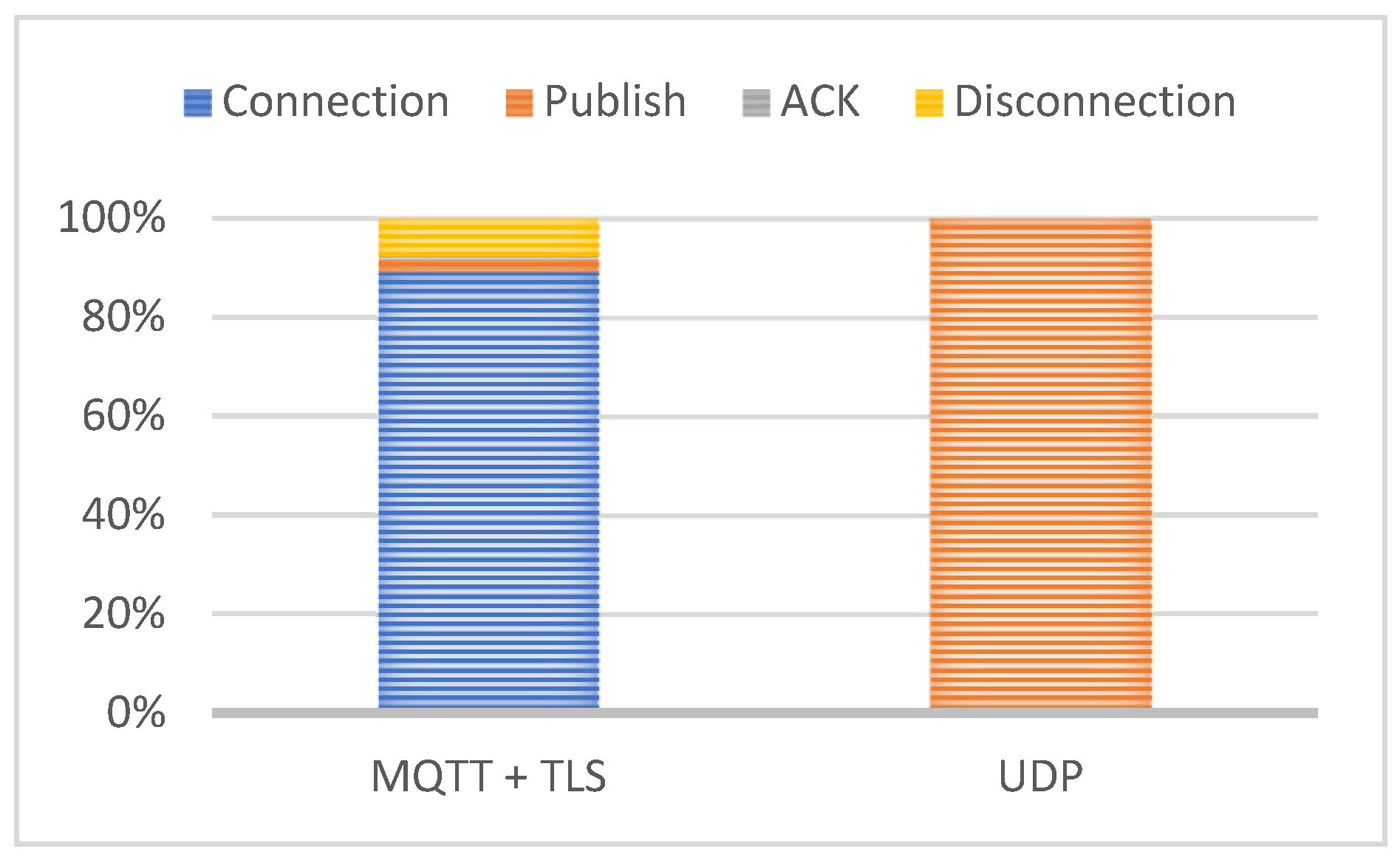
| UDP | 1.17mWh | 2.15mWh |
| MQTT-TLS | 2.82mWh | 2.64mWh |
Disclaimer/Publisher’s Note: The statements, opinions and data contained in all publications are solely those of the individual author(s) and contributor(s) and not of MDPI and/or the editor(s). MDPI and/or the editor(s) disclaim responsibility for any injury to people or property resulting from any ideas, methods, instructions or products referred to in the content. |
© 2025 by the authors. Licensee MDPI, Basel, Switzerland. This article is an open access article distributed under the terms and conditions of the Creative Commons Attribution (CC BY) license (http://creativecommons.org/licenses/by/4.0/).