1. Introduction
The liquid metal cooled reactors can be considered the future of nuclear plants due to of their potential for breeding efficiency and, consequently, economic justification. This type of reactor can achieve high coolant temperatures. Metal coolants remove heat from reactor core more rapidly, allowing for much higher power density. In other words, by using this type of reactor offers several advantages simultaneously, including economic viability, high power density and high coolant temperature.
The first experimental fast reactor was built in 1946 at Los Alamos. It was operated until 1953. The reactor was fueled with 2.5 liters of metallic plutonium, and the reactor core was cooled by mercury [
1]. In 1951, first experimental fast breeder reactor, EBR-I, which generated practical amount of useful power of 200 kWe, was constructed at the National Reactor Testing Station in Idaho [
1]. Eutectic sodium-potassium served as the coolant of the reactor. Unfortunately, there are only about 20 experimental and commercial fast neutron reactors in operation worldwide [
2,
3]. One reason for this limited number is that fast reactors are typically cooled by liquid metal and have positive value of α
V coefficient, making it difficult to reduce this coefficient.
The negative value of αV is a fundamental property of passive safety of all types of nuclear reactors. The second important is the passive removal of shutdown heat after the loss of coolant accident.
During recent years there has been stagnation in the development of liquid metal cooled fast reactors. However, the interest in fast reactors has been renewed due to necessity of limiting CO
2 emission and addressing global warming [
1,
2,
3,
4,
5,
6,
7,
8,
9,
10,
11,
12,
13,
14,
15,
16,
17,
18,
19,
20,
21,
22,
23,
24,
25,
26,
27].
Fast reactors have nuclear characteristics that enable efficient use of uranium fuel and the capability to burn the long-lived actinides found in nuclear wastes [
2]. The paper [
2] presents the results of calculation of reactivity feedback for Sodium Fast Reactor (SFR) with U-cycle are presented. It provides a detailed a description of neutron physics and includes calculation results obtained by the perturbation method for voided condition in the SFR. Unfortunately the study does not provide estimated value of α
V.
To mitigate the overall reactivity increase during an accident, different concepts are used, including axial fuel expansion and radial core expansion. The core shape expansion is a passive method that utilizes thermal expansion and bowing of the ducts [
4,
5]. Additionally, there are other methods such as control rod driveline expansion or a special coolant cavity over core to reduce the α
V, as well as a passive shutdown system with hydraulically suspended rods [
4,
5].
The estimation of the value of α
V was studied in a water cooled reactor with a flexible fuel cycle which is a type of Boiling Water Reactor (BWR) [
11]. In the work exact perturbation calculations were applied, which quantitatively estimate α
V as a function of fuel rod diameter.
The effect of the distribution of voids inside the reactor on α
V was studied in the Na-cooled FBR-IME reactor, based on the Japanese JOYO experimental reactor. The central part of the reactor consist of 95 heterogeneous fuel assemblies, while peripheral part (outer/fertile) consist 295 assemblies of U-238 [
12,
13]. The peripheral part is used for conversion of U-238 to Pu-239. Unfortunately, it also plays a role as a reflector, which increases α
V. This work provides exact result of α
V for several distributions of no-sodium assemblies in central part of reactor.
The void reactivity was studied as affect of an unprotected loss of flow event (ULOF) in the MOX-fueled core based on the prototype reactor MONJU [
14,
15]. This reactor also utilized an inner core and an outer/fertile region.
Saturation concentration of U-233 in Th-cycle achieves 0.11 in fast reactor, while in in thermal reactor it is only 0.0137 [
16,
17]. Breeding and criticality in Th-cycle occur simultaneously in fast reactor, only [
18]. In other words, to achieve the most effective and safe thorium reactor, a fast reactor with a negative value of α
V should be constructed [
17,
18,
19].
Two large FSRs (3600 MWth): MOX-3600 and CAR-3600, and two medium FSRs (1000 MWth): MET-1000 and MOX-1000 and with different fuel types were compared in Ref. [
20]. This excellent work presents various technical parameters of these reactors include numerical values of α
v for 100% void. All values of α
v are positive.
The reactors with a low value of αv referred to as ‘the low void worth core’(CFV) possess relatively complex core geometries. The cores are designed with radially or axially heterogeneous geometries, incorporating sodium plenums, fuel zones, fertile zones and absorbing zones. There are several reactors based on low void worth cores including the Russian reactor BN-800 [
21,
26], the Japanese concepts of Takeda [
24,
25,
26] and Saito [
23,
26] and the French concepts CFV of Sciora [
26] and ASTRID CFV of Beck [
27]. For the CFV concept, the value of α
v is positive when a decrease in coolant density occurs in central part of the core (fissile and fertile zone) and negative when it occurs in the upper sodium plenum zone. This concept does not eliminate the risk of sodium boiling.
A characteristic feature of CFV cores is the leakage of neutrons primarily through the upper sodium plenum, during the voided conditions. This concept restricts the neutron leakage to the top of core base, which in turn limits the height of the active core.
This paper presents a concept of Hybrid reactor in which neutron leakage primarily occurs through the radial side area of the core. This approach allows for a higher value of neutron leakage rate that is proportional to the height of the core. The Hybrid concept consist two kind of fuel assemblies; assemblies with high enrichment fuel placed in the peripheral region and assemblies with low enrichment fuel located in central part of core. The study focuses on examination the influence of average fuel density and coolant volume fraction in the fuel cell on the decrease the value of αv.
Additionally, the calculation results from Hybrid model are compared to experimental data from FBR-IME (Sec.8, [
12,
13]). The calculation results were obtained using Monte Carlo method, specifically employing the MCNP6.2 code [
28].
2. Materials and Methods
The computer simulation model is based on the geometry of European Pressurized Reactor (EPR) [
29,
30]. This geometry was chosen because a large reactor core was necessary to study α
V in a general context. The modified model incorporates various type of coolants i.e., liquid sodium (Na) or lead (Pb). Additionally, it accounts for changeable volumes of fuel and coolant (
Figure 1,
Figure 2,
Figure 3,
Figure 4 and
Figure 5 and
Table 1,
Table 2 and
Table 3) as well as different numbers of fuel assemblies [
18,
19]. The reactor core model consists 241, 137 or 101 assemblies (
Figure 1,
Figure 2,
Figure 3 and
Figure 4). We use the A1 assembly in the reactor model, which employs a single type of fuel rod (
Figure 6, [
29]). The fuel is a mixture of U-238 and Pu-239 or Th-232 and U-233 to study the U-cycle and Th-cycle, respectively. Furthermore, three different values of fuel density are applied.
The reactor model has a changeable fraction of coolant in the volume of the fuel cell (VCR)
The values of VCR parameters are in the width range of < 0.239, 0.976>.
Other parameter often used in literature is volume ratio of coolant and fuel (VCFR)
It is assumed that, the thickness of cladding of fuel rods is equal to zero. For this reason VCFR=VCR/(1-VCR). This assumption is made to reduce the number of computations. It is a simplified model, intended solely for computational purposes, rather than for experimental research.
The wide range of values of the VCR or VCFR (
Table 1) parameters enables studying a broad range of neutron flux spectrum (Sec.4). However in the Hybrid reactor was used only practical values of these parameters. This reactor model can achieve neutron flux characteristics typical of a fast reactor. For example, the average neutron energy (ANE) in fuel rods reaches 0.5 MeV, while the average neutron energy causing fission reaction (ANFE) for Hybrid reactor based on Na-cooled U-cycle is approximately 0.9 MeV in normal operating conditions and 1.1MeV for voided core state (Sec. 6).
The change of the VCR or VCFR parameter of the reactor model can be achieved by using assemblies with appropriate cell configurations, which entail the suitable fuel and coolant volumes (
Figure 5,
Table 1).
To reduce the density of fuel one can utilize porous materials or fill part of the fuel volume with air, for example. The simplest method for decreasing the average fuel density of fuel rods is to fill the central part of the rods with air.
The initial value of the effective multiplication factor (k
eff) is in the range of 1.05±0.02 for all cases. Uncertainty of α
V is discussed in Sec.7. In other words, the initial enrichment of fuel was determined for each case before the reactor was voided for all values of the VCR parameter, fuel type and geometry. Herein the reactor may contain one type of fuel assemblies (
Figure 1,
Figure 2 and
Figure 3) or two type fuel assemblies (Hybrid reactor, see
Figure 4). The base parameters of the reactor cores are presented in
Table 3. The core configuration presented in
Figure 3 consists of 137 assemblies, referred to as the ‘small core’ or 101 assemblies, referred as the ‘very small core’.
3. Definitions
There are different definitions of void reactivity coefficient [
11]. For example, the “void reactivity coefficient” for BWR is defined as α
V at which the coolant flow rate reaches 90% of the nominal value [
11]. In other case, the coolant is fully flow out, and the reactor vessel is filled with saturated steam. This case, is named as ‘‘the 100% void reactivity coefficient’’. The following definition of α
V is presented in ref. [
11]
where,
αV: void reactivity coefficient
k1, k0: effective multiplication factor at void fraction of V1 and V0, respectively:
V1, V0: void fraction at varied and nominal condition [%], respectively:
The definition in Eq.(1) suggests that αV is a linear function of the void fraction.
However, this is not accurate, as αV is not generally a linear function (Sec.4 and 5).
For this reason, we employed the following definition of
αV:
where,
void [%] is an average value of the void fraction in the fuel cells,
knorm, kvoid means effective multiplication factors at normally work and voided reactor core respectively.
The following definition often is used:
where,
, indicate the reactivity of reactor under normal operating condition and in a voided reactor core, respectively.
The definitions of αV and are compared in Sec.7.
The definitions provided by Eq.(2 and 3) are more general than that of Eq.(1) because they do not assume a linear void dependence of on the void fraction. In other words, all values of are calculated directly for each specific value of void parameter.
means 0% of coolant density. This means that the volume of coolant is filled by air at atmospheric pressure. This case simulates the Loss of Coolant Accident (LOCA).
means that n% of part of coolant is evaporated and average density of coolant is equal to (100-n)% of its normal value. The normal value of coolant density is equal to the density of liquid metal.
The magnitude
depends on a various parameters such as the VCR parameter or the type of fuel, and the size and shape of the reactor core (See Sec.4). If we are interested in
as a function of the VCR parameter and constant value of void, we can write it in the following form:
Whereas, if we are interested in
as a function of void parameter and with constant value of the VCR parameter we can express it in the following form:
Both function and are not linear functions of void and VCR parameters (See Sec.4 and 5).
4. Calculation Results for the Reactor Core Filled by Single Type of Assemblies
This section presents
for geometry of reactor cores depicted in the
Figure 1,
Figure 2 and
Figure 3, considering different parameter values as VCR, type of fuel, type of coolant, geometry and fuel assembly (
Table 3). In this section we assume that the reactors consist of a single type of fuel assembly. The initial values of fuel enrichments are the same for both normal operation and during reactor void condition.
The
Figure 7,
Figure 8,
Figure 9 and
Figure 10 present values of
for different types of core (
Figure 1,
Figure 2 and
Figure 3) and various combinations of fuel and coolant (from
Table 3). These values can be both positive and negative. The values of
(VCR) are important because they indicate maximal positive value of
and minimal negative value for maximal value of the void parameter.
A very important is the value of parameter for which ()=0. This is significant because for VCR<, it is not possible to obtain negative value of . For these values of the VCR parameter reactor does not passively decrease the number of neutrons during the LOCA accident. In contrast, for reactors with a VCR greater than , the value of becomes negative, indicating that the reactor should be turned off during this accident. Please note that is a characteristic parameter of a class (set) of reactors that differ only in the VCR parameter.
All the functions have negative values for sufficiently high values of the VCR parameter. For this reason, the VCR parameter is the most important factor to reduce the value of .
The greatest positive values of
one can be achieved with large cores or small cores that incorporate a reflector and for metallic fuel of U-238+Pu-239 (
Figure 7,
Figure 8,
Figure 9 and
Figure 10). For this reason both a reflector and high value of a fuel density are unfavorable when the goal is to reduce the value of
.
The lower positive values of
are obtained for the thorium cycle (
Figure 9 and
Figure 10). The primary reason for this result is the lower density of metallic thorium compared to that of metallic uranium (see Sec.6).
The negative value of
one can obtain especially easy for Pb-cooled Th-cycle (
Figure 10). For this type of reactor, it is possible to obtain negative value of
over a wide range of VCR parameter values.
The
function is partially increasing and decreasing function of
VCR parameter for low and high value of
VCR parameter, respectively. The absorption and leakage components of α
v are responsible for the increasing and decreasing part of the α
v function, respectively. To obtain negative value of α
v than the leakage component must be greater than the sum of absorption and spectrum components α
v [
26].
The components mentioned above are closely interconnected. A high value of VCR indicates a high positive value of absorption component; however, this does not necessarily imply a higher value of αv. In fact, a high value of VCR parameter generally corresponds to lower value of fuel mass in the fuel cell which increases the leakage component. As the VCR value becomes sufficiently high, αv tends to decrease.
The small core makes it easier obtaining the negative value of
for different type of reactors cores without reflectors (
Figure 7,
Figure 8,
Figure 9 and
Figure 10). This finding extends the existing literature [
2,
3,
4,
5,
6,
7,
8,
9,
20]. However, another significant parameter that decreases the value of
is the density of the fuel (
Figure 7). The most effective method of reducing of
is applying the three methods simultaneously: reducing fuel density, decreasing the size of core and increasing the value of VCR parameter (
Figure 7,
Figure 8,
Figure 9,
Figure 10 and
Figure 11).
The average fuel density plays important role in decreasing the value of
. Unfortunately only a very small core with fuel density of 6 g/cm
3 achieves a
value of less than 0.5. The method of reducing the average density of the fuel does not practically allow for the construction of a large reactor filled solely with one type fuel assembly with a negative
(
Figure 11).
Please note that the above conclusion applies to reactor core containing only one type of fuel assembly of U-cycle.
The large and medium reactors presented in Ref. [
20] have reflectors and positive value of αv.
The results in this section predict that large reactors without the reflectors also exhibit a positive value of αv. Why is it so difficult to obtain a low value of ? This is because decreasing simultaneously increases the fuel mass in the fuel cell, which in turn decreases neutron flux leakage.
Unfortunately, the results presented in this section exhibit a high value of . However, they provide guidance on how to significantly reduce this quantity (see Sec. 6).
5. Loss of Neutrons
This section presents relation between α
v and neutron loss coefficient
Loss Eq.(4), and
βv Eq.(6) as a functions of VCR parameter. The fraction of lost neutrons can be defined in the following form:
where:
Absorption - means absorption fraction without absorption neutron induce fissions i.e., (n,γ)
Escape - means total escaped fraction of neutrons,
Fission - means fraction of all actinides fission reaction.
Loss is a function of VCR and void parameter.
The
βv function can be defined as relative change in the
Loss(VCR) function
where
Lossnorm, Lossvoid – means loss neutrons fraction at 0% void (normal work) and n% void respectively.
The
Incore(VCR) function can be defined as the neutron fraction inside the core in the following form:
Comparisons between
and
for the Pb-cooled U-cycle in a small core reactor as a function of the VCR parameter are presented in
Figure 11. Similarly, we obtained relationships between
and
for all cases discussed in this work.
It is important to note, that has negative and positive values. The positive values means positive values of and decreasing number of neutrons in the core. Conversely, negative value of suggests an increases in the number of neutrons in the reactor core. In other words, the presence of void can either increase or decrease the neutron populations in the core, which, in turn, changes the sign of .
Please note, that the
ΔLoss fraction is equal to the negative value of the
Δfission fraction (
Figure 12). In other words, the positive value of the
ΔLoss fraction indicates a decrease in the fission fraction and a negative value of
. The primary reason for this is the high value of
ΔEscape fraction during evaporative cooling. The calculations results take into account changes of neutron flux energy distribution and cross sections of corresponding reactions during reactor voiding. Specifically, the results consider the increase in fission cross sections induced by an increase in the average neutron energy. However, this increase in the fission cross section can be mitigated by decrease in the neutron fraction within the reactor core, which is caused by in neutron escape. The
Incore(VCR) function can be useful for illustrating this effect (
Figure 12).
Figure 12.
The , and for U-cycle and coolant of Pb, Small core.
Figure 12.
The , and for U-cycle and coolant of Pb, Small core.
Figure 13.
Change of the Escape, Absorption, Loss, Fission and Incore fraction during 50% void. Small core.
Figure 13.
Change of the Escape, Absorption, Loss, Fission and Incore fraction during 50% void. Small core.
The results obtained in this section help us to get negative value of for Hybrid reactor (see Sec.6.).
6. Calculation Results for Hybrid Reactor
Using results from the previous sections we can derive intriguing outcomes for the Hybrid reactor (
Figure 4,
Table 3). Hybrid reactor contains two part of core: central core and peripheral core. The central core contains fuel assembly with an optimal value for the VCR=0.485 (VCFR=0.94) parameter, standard fuel density and a low value of fuel enrichment. In contrast, the peripheral core is composed of fuel assembly with a high level of fuel enrichment and three values of both the VCR parameter and fuel density. By simultaneously utilizing these three above parameter characteristics for the peripheral assemblies, we achieve the smallest values of
. The calculations were conducted with of central fuel enrichments of 1 and 5 % for U-cycle and Th-cycle. The enrichment of peripheral fuel was adjusted to ensure k
eff=1.05±0.02.
Herein two examples of Hybrid reactors are presented: Na-cooled U-cycle and Pb-cooled Th-cycle. It is important to note that the Na-cooled U-cycle predicts maximal values of
whereas the Pb-cooled Th-cycle exhibits minimal values of
when reactor core is filled with a single type of assemblies (compare
Figure 7,
Figure 8,
Figure 9 and
Figure 10).
The Pb-cooled Th-cycle Hybrid reactor has significantly lower value of
compared to the corresponding Na-cooled U-cycle (
Figure 14 and
Figure 15). This indicates that Th-cycle reactors are characterized by substantially greater passive safety than U-cycle reactor.
The values of
are significantly less than 0.485 for all presented cases. While exact values of
were not calculated but one can be easily estimated using the
function and extrapolation method (
Figure 14,
Figure 16 and
Figure 17). It is important to note, that the values of VCR for central and peripheral part are significantly greater than
. This can be expressed in the following inequalities: VCR
central>
and VCR
peripheral>
. These results indicate that
has negative value (see Sec.5).
The negative value of
can be explained in another way. Please note, that the value of
is positive for all the cases presented in this section (
Figure 16). A positive value of
always corresponds to negative value of
(Sec.5). The primary reason of positive value of
is a high value of
ΔEscape quantity which indicates an increase of escaping neutrons in a voided reactor core, an increase in
ΔEscape leads to decrease in
ΔIncore, that is, it reduce the fraction of neutrons in the core. The relative increase in
ΔEscape exceeds 60% and the average energy of the escaping neutrons increases by more than 20%. This results in reduction the average value of neutron flux density in the peripheral part of the core (
Figure 17.). Consequently this leads to a decrease in fission reaction within the core, as evidenced by the negative value of
Δfission Figure 18).The
Δfission fraction is negative for all samples presented in this section.
Please note on the cases of VCR=0.485 and normal value of fuel density for both central and peripheral assemblies. In these scenarios, a significant difference in fuel enrichment between peripheral and center is sufficient to obtain negative value of . This phenomenon occurs because the Hybrid reactor consist high fuel enrichment in peripheral region and allows a high value of leakage neutrons during voided reactor. Please note, that analogical large reactor Na-cooled U-cycle based on single type of assembly has =0.827 and positive value of .
One can observe that
is a decreasing function of peripheral VCR parameter (
Figure 14) and an increasing function of peripheral fuel density (
Figure 15). In other words, the negative value of
is decreasing function of the both difference of fuel enrichment, fuel density, as well as the VCR parameter between central and peripheral parts (
Table 4 and
Table 5,
Figure 15).
The ANE and ANFE have a weak dependence on the peripheral fuel density (
Figure 16). However,
is an increasing function of peripheral fuel density. For these reasons, it is advantageous to reduce the peripheral fuel density.
The type of coolant and fuel has a significant impact on the
value. The higher value of cross section on neutron absorption of coolant increases of
value. An important factor contributing to an increase in
is the increase in the number of fission reaction induced by fast neutrons (
Table 6) and ANFE for the voided reactor core (
Figure 19 and
Figure 20). These magnitudes have significantly greater values for the U-cycle compared to the Th-cycle. The reason for this is that the fission cross section (FCS) for U-233 is higher than that of Pu-239 in the intermediate neutron energy range (
Table 6). Additionally, the FCS for Th-232 is lower than that of U-238 for neutron energies higher than 0.5 MeV. Number of directly fission events of U-238 is significantly greater than Th-232.
The geometry of Hybrid reactor presented in this section is not yet optimized. Furthermore, reducing of the value of can be achieved by increasing the outer surface area of peripheral part at the top and bottom of the core, for example.
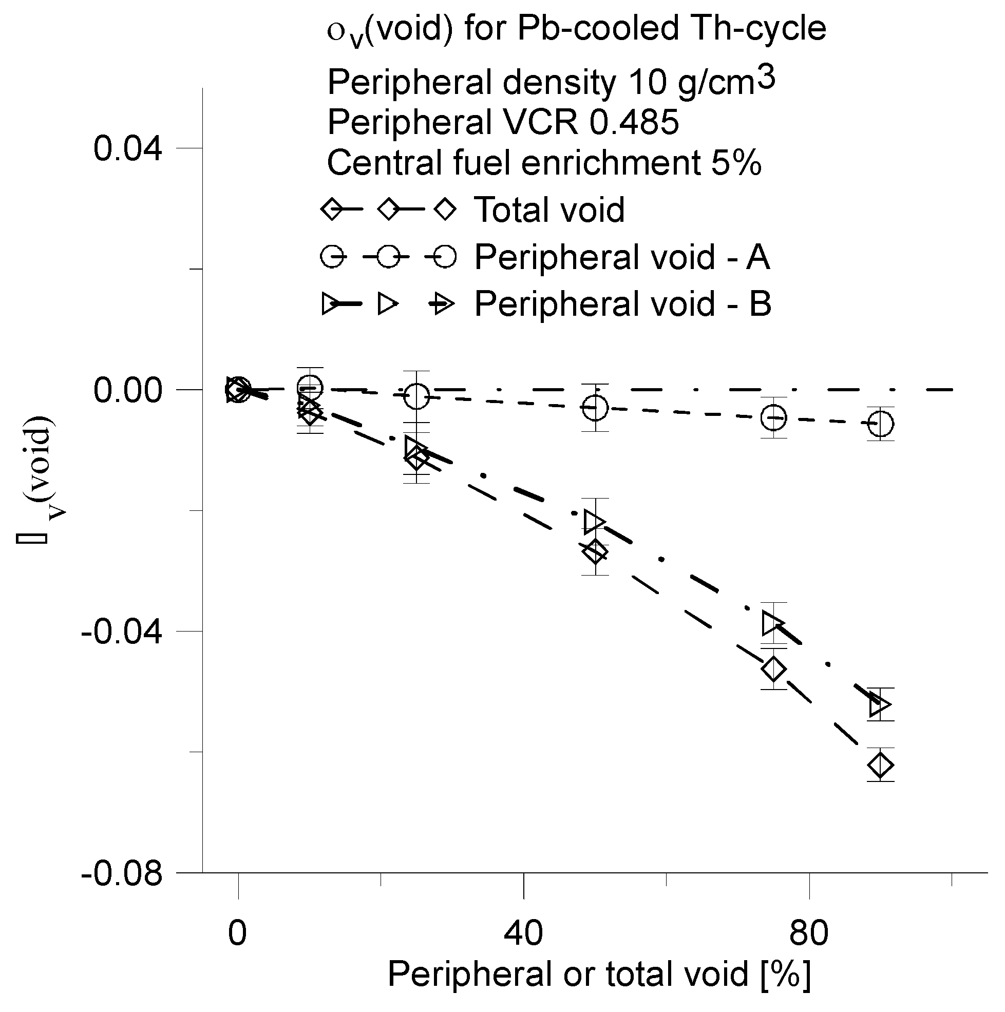
Herein is , is primarily calculated. However neutron flux density, power density and evaporation rate of the coolant in peripheral region are significantly greater than in central region. For these reasons, the rate of decrease in the coolant density in peripheral region will be greater than in the central region. Why is which functions were calculated for both total void and peripheral void. The αv for the peripheral void was calculated for two cases: Partial Void-A and Partial Void-B.
Partial void–A refers to the case in which the average coolant density was changed only in the peripheral assemblies. In this scenario, the thin layer of coolant between the fuel assemblies and core barrel has a constant normal density. This situation does not reflect a real case.
Partial void–B, on the other hand, describes the case in which the average coolant density was modified in the peripheral region of reactor specifically in the peripheral assemblies and the thin layer of coolant between the fuel assemblies and the core barrel. This represents a more realistic scenario.
The difference between Partial Void-A and Partial Void-B predicts a significantly impact of the peripheral thin layer of coolant on the αv.
The concept of Hybrid reactor allows for the construction a large and efficient reactor with a negative value of
. A low value of central fuel enrichment allows the use of natural uranium or thorium, as the criticality of Hybrid reactor is determined by peripheral part of reactor. In other words the central region should be consists blanket/fertile assemblies for conversion fuel. The fuel conversion ratio (CR) is decreasing function of fuel enrichment. For this reason the CR for peripheral region will be less than 1 [
17,
18].
Influence of the Central Region Parameters on αv
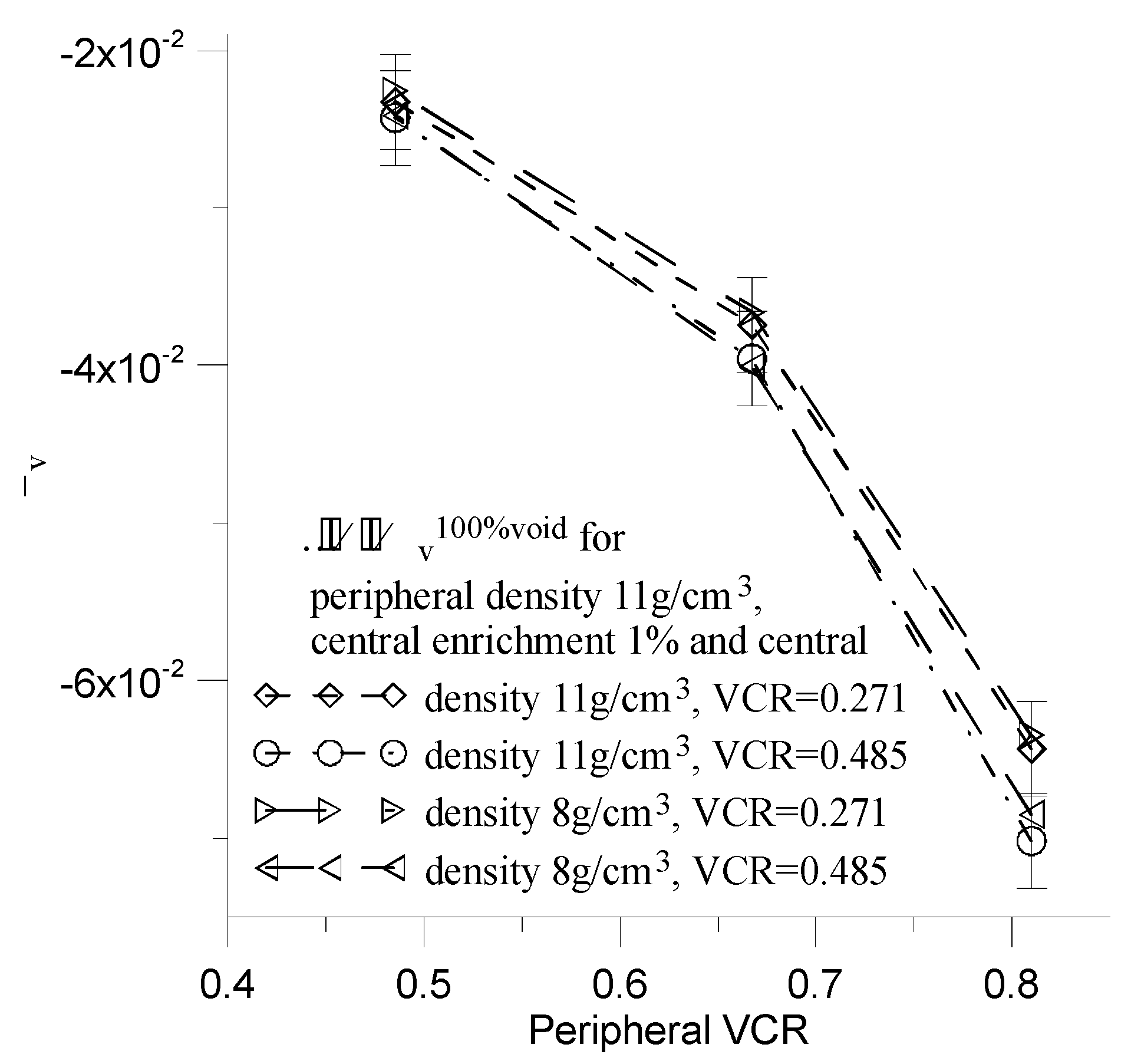
In this section, we examine the influence of the central region parameters: the average fuel density and the central VCR parameter on αv, while the central fuel enrichment maintained at a stable level of 1%.
The peripheral fuel density is set at 11 g/cm3, and the peripheral VCR values are 0.485, 0.667, 0.810.
We compare the
functions for central fuel densities of 11 g/cm3 and 8g /cm3, as well as central VCR values of 0.271 and 0.485 (
Figure 22).
The fuel density of central core region does not influence on the α
v (
Figure 22). However, the central VCR has a weak influence on α
v. Strictly speaking, a decrease in the central VCR parameter of about 44 % induce an increase in the relative value of α
v of approximately 4-9%. The decrease value of the central VCR parameter decreases absorption component of α
v, which should lead to a decrease in α
v. The slight increase in α
v suggests that the absolute value of leakage component of α
v simultaneously decrease. In other words, from point of view of α
v, there is no need to employ a very low values of central VCR in the Hybrid reactor. One can employ them to increase average neutron energy.
7. Calculation Uncertainties
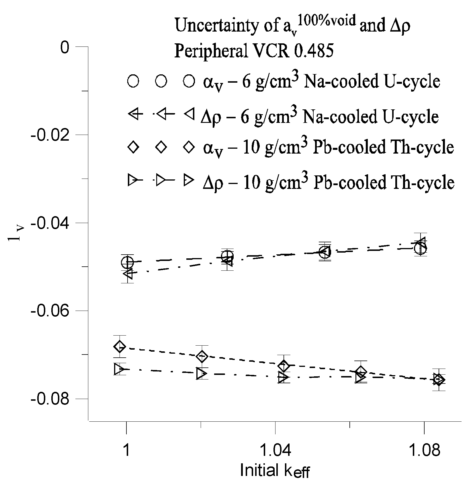
This section presents the values of the uncertainties for both the αv (Eq.(2)) and the difference in reactivity defined by Δρ (Eq.(3)).
The Δρ and α
v are functions of initial value of k
eff (
Figure 23). Calculated uncertainties of α
v and Δρ include both the systematic error due to the uncertainty of the initial value of k
eff and standard deviation resulting from the statistical errors of initial values of k
eff (
Figure 23).
Maximal value of the systematic error (MSE) in the range Δkeff=0.02 is calculated using corresponding fitting function of αV(keff) and Δρ(keff) for Na-coolled U-cycle and Pb-cooled Th-cycle respectively.
The standard deviation of reactivity σ(ρ) was determined using standard deviation σ
keff of k
eff and the following formula:
The standard deviation of Δρ is calculated using the following formula:
The standard deviation of α
v is calculated from the following equation:
Total uncertainties of α
v and Δρ for 100% void are equal to sum of standard deviation and MSE. These are denoted as Δ
Tot(α
v) and Δ
Tot(Δρ), respectively (
Table 7).
Total uncertainty
of
αv(void) function (
Figure 21) is determined by perturbation effective multiplicity factor
and its standard deviation
and MSE. The perturbation error was calculated for 10% of average coolant density using PERT command of MCP6.2 code. Maximal value of
achieves 0.004 for void=20%.
8. FBR- IME Reactor Versus Hybrid Model
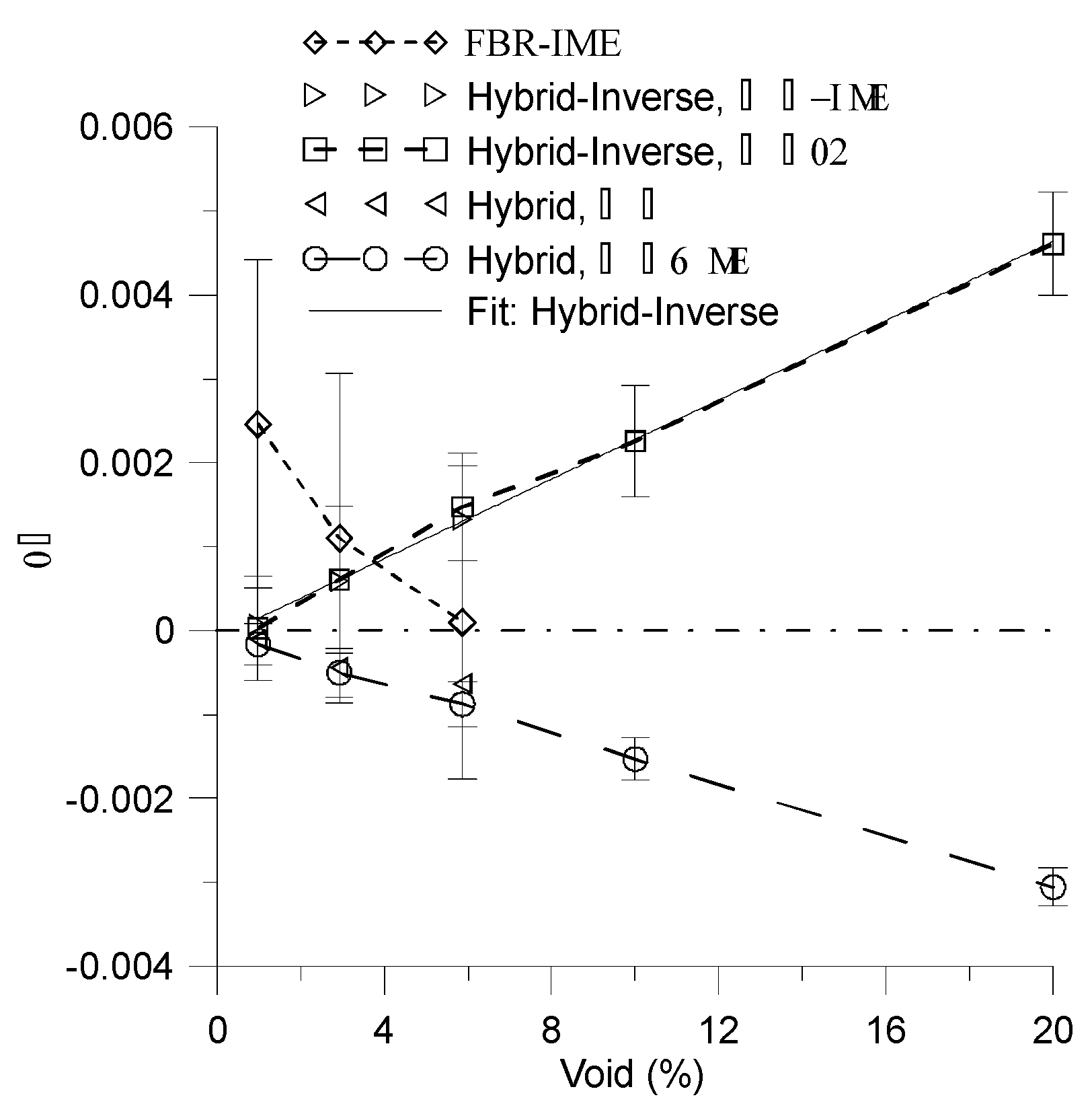
The main aim of the section is compare the difference in reactivity Δρ of FBR-IME [
12,
13] and Hybrid reactors for low value of average void. The Hybrid reactor is based on VCR parameter of 0.485 and fuel density of 11g/cm3 and central fuel enrichment of 1%. In addition, the Hybrid-Inverse reactor is presented. The geometry of this model is identical to that of the Hybrid reactor, but assemblies with fuel enrichment of 1% are placed in peripheral region, while assemblies with high fuel enrichment are positioned in central part of reactor (likely as in FBR_IME, (see
Table 8).
The Δρ for Hybrid reactors are calculated for two different values of ρ. The difference between them are less then correspondent value of standard deviation (
Figure 24 and
Table 8).
The low value of void results low value of difference in reactivity Δρ and requires high value of statistics. For this reason measurement of Δρ is a difficult task. The standard deviations of Δρ for voids of 2.93% and 5.87% for FBR_IME are significantly greater than corresponding values of Δρ [
Table 8,
Figure 24] and also exceed the corresponding values of Hybrid-Inverse reactor. However, the results of Δρ are likely applicable to both FBR-IME and Hybrid-Inverse. Despite the many differences between FBR-IME and Hybrid-Inverse reactors the results are practically the same in the range of experimental and calculation errors. Strictly speaking, the differences between Δρ for void of 2.93% and 5.87 % are approximately to 0.0005 and 0.0014, respectively. These differences are both less than corresponding standard deviation of FBR-IME. Whereas, this difference for void of 0.98% is approximately 0.0024 which is less than sum of corresponding deviation of FBR-IME and Hybrid-Inverse.
These reactors have a low value of fuel enrichment in the peripheral region (blanket/fertile) (
Table 8, [
12,
13]).
The Δρ(void) is a decreasing function of void for both the FBR-IME and Hybrid reactors within the range of (0.98%, 5.87%) void. However, the FBR-IME exhibits a positive, whereas Hybrid reactor a negative value of Δρ. Special arrangement of high enrichment MOX fuel assemblies in the central part of the FBR-IME is insufficient to achieve a negative value of Δρ.
The Hybrid model results a negative value of Δρ for all cases. In this scenario the average coolant density was modified in total peripheral region of reactor, which includes the peripheral assemblies and thin layer of coolant between the assemblies and the reactor barrel.
It is important to note, that blanket/fertile assemblies placed in the center part of the reactor significantly decrease Δρ (
Figure 24,
Table 8), while those placed in peripheral part acts as reflector and increase Δρ (see Sec.4).
The is calulated using Eq.(8).
The standard deviation σ(α
v) of
should be determined from the following formula:
If we assume that =0 that Using above equations one can easy show that . It means that relative values of αv and of are the same. In real reactor the uncertainty of Δv can be significantly greater than 0. This implies, that the total relative uncertainty of αV can be considerably greater than total uncertainty of Δρ. For this reasons we compare Δρ in this section.
9. Discussion
The choice of Hybrid reactor geometry was made due to it has large core without both a reflector and an upper sodium plenum (compare Ref. [
27]). The Hybrid reactor has all features of fast reactor with negative αv (Sec.6 and 8). Its core has relatively simple geometry and special arrangement of fuel assemblies optimized for leakage neutron flux during void conditions.
The purpose of this section is to present the main differences between a fast reactor core and a PWR core, as well as to explain their influence on the value of αv.
-On top of that, the active fuel zone in SFRs and LFRs should be only about 1 meter due to significant concerns about the core void reactivity, which is much shorter than in the conventional PWRs.
The high value of active zone is intentional and is chosen to exhibit that a negative value can still be achieved even with an elevated core height.
Reducing the height of the active fuel zone to about 1 m is advantageous from the perspective of αv and can be applied in Hybrid concept, as it increases the neutron leakage fraction and decreases αv.
-In the case of sodium-cooled fast reactor (SFR), the fuel lattice should be very tight to minimize the void reactivity and all SFR designs are based on the hexagonal lattice.
The neutron flux spectrum and average value of neutron energy do not depend on the type of lattice. Instead, they are influenced mainly by the VCR or VCFR parameter. The Hybrid reactor is designed based on the practical value of these parameters (i.e., central region VCR=0.485 or 0.271 (
Figure 22) and average value of neutron energy is being approximately 0.5MeV. The square and hexagonal fuel lattices are described as options of fast reactor in Reference [
7]. In other words, the hexagonal lattice can be used in Hybrid reactor without changing α
v. The minimal value of VCR parameters for FBR-IME and Hybrid reactor are equal to 0.374 and 0.271, respectively.
-In addition, there should be thick steel reflector in both radial and bottom sides of the core.
Excessive core height affects αv in a manner similar to that of a thick bottom and top reflector. This means that the thick bottom reflector is included in the calculation results of Hybrid reactor. However, the thick radial side reflector presents challenge that needs to be addressed. This reflector should be removed. Additionally, the blanket/fertile should be positioned at the center of the core.
-Actually, there are significant differences in the core configurations between fast reactors and PWRs.
While there are many technical distinctions between the core of fast reactors and PWRs, the neutron flux spectrum and neutron physics in the Hybrid reactor are similar to those in fast reactors. Many technical concepts from fast reactors such as bending fuel assembly or upper gas plenum can be applied in concept of Hybrid reactor in construction future fast reactors with negative value of αv.
10. Conclusions
The Hybrid reactor concept offers the very effective passive and promising method for achieving a negative αv value for a wide range of basic reactor parameters (Sec.6).
The fuel density and VCR parameter are important reactor parameters, reduces value of α
v (Sec.6). Decrease average fuel density and increase VCR parameter in peripheral fuel assemblies induce decrease α
v. (Sec.6,
Figure 14 and
Figure 15).
The parameter is a very convenient parameter for determining the reduction value of αv. Reducing this parameter is crucial for decreasing the value of αv. Additionally, this parameter can be used to compare different method of reducing αv. To achieve a negative αv value, the reactor must have a VCR value exceeds (Sec.4).
Particularly noteworthy is low value of αv for Pb-cooled Th-cycle Hybrid reactor (Sec.6).
Herein are presented calculated results for liquid Pb and Na cooled reactor, only. However, the Hybrid concept can be useful for obtaining the negative value of αv in reactors cooled by other liquids.
Abbreviations
The following abbreviations are used in this manuscript:
| VCR |
Volume fraction of coolant in the cell |
| VCFR |
Volume ratio of coolant and fuel in the cell |
| FBR-IME |
Brazilian Fast Breeder Reactor |
| αV
|
Void reactivity coefficient |
| βV
|
Loss of neutrons function |
| ANE |
Average neutron energy in the fuel rods |
| ANFE |
Average neutron energy causing fission reaction |
| ρ |
Reactivity |
| Δρ |
Change in reactivity |
| CVF |
Low void worth core |
| knorm
|
effective multiplication factor at normally work |
| kvoid
|
effective multiplication factor at voided reactor core |
| MSE |
Maximal value of the systematic error |
| σ |
Standard deviation |
| ΔTot
|
Total uncertainties |
| SFR |
Sodium Fast Reactor |
| FBR |
Fast Breeder Reactor |
| LFR |
Lead Fast Reactor |
References
- Massud Simnad, Overview of Fast Breeder Reactors, Energy Vol. 23, No. 7/8, pp. 523–531, 1998. [CrossRef]
- W.S.Yang, Fast Reactor Physics and Computational Methods, Purde University School of Nuclear Engineering West Lafayette, USA 2011.
- Fast Neutron Reactors (updated August 2011), World Nuclear Association Website, https://world-nuclear.org/information-library/current-and-future-generation/fast-neutron-reactors.aspx.
- IAEA, Fast Reactors and Related Fuel Cycles: Challenges and Opportunities FR09, Proceedings of an International Conference Fast Reactors and Related Fuel Cycles: Challenges and Opportunities FR09 Kyoto, Japan, 7–11 December 2009.
- T. Yokoo, H. Ohta, ULOF and UTOP Analyses of a Large Metal Fuel FBR Core Using a Detailed Calculation System, Journal of Nuclear Science and Technology, Vol. 38, No. 6, p. 444–452 2001. [CrossRef]
- IAEA, Operational and decommissioning experience with fast reactors, Proceedings of a technical meeting, IAEA-TECDOC-1405, France, 11–15 March 2002.
- A. Alemberti, J. Carlsson, E. Malambu et al., European lead fast reactor—ELSY, Nuclear Engineering and Design,Vol. 241, Issue 9, Pages 3470-3480 (2011). [CrossRef]
- J.C.Lefevre, C.H.Mitchell, G.Hubert, European fast reactor design, Nuclear Engineering and Design 162, 133-143, (1996). [CrossRef]
- IAEA, Modeling and Simulation of the Source Term for a Sodium Cooled Fast Reactor Under Hypothetical Severe Accident Conditions Final Report of a Coordinated Research Project, IAEA-TECDOC-2006.
- IAEA, Structural Materials for Heavy Liquid Metal Cooled Fast Reactors Proceedings of a Technical Meeting, IAEA-TECDOC-1978.
- Y. Fukaya, Y. Nakano and T. Okubo, Study on Characteristics of Void Reactivity Coefficients for High-Conversion-Type Core of FLWR for MA Recycling, Journal of Nuclear Sciene and Technology, Vol. 46, No. 8, p. 819–830 (2009). [CrossRef]
- Fabiano P. C. Lima, et al., Accurate Reactivity Void Coefficient calculation for Fast Spectrum Reactor FBR-IME, 2017 International Nuclear Atlantic Conference - INAC 2017 Belo Horizonte, MG, Brazil, October 22-27, 2017 ASSOCIAÇÃO BRASILEIRA DE ENERGIA NUCLEAR – ABEN.
- Fabiano P.C. Lima, ANÁLISE GLOBAL DO COEFICIENTE DE REATIVIDADE DE VAZIOS PARA O REATOR DE ESPECTRO RÁPIDO FBR-IME, Dissertation, INSTITUTO MILITAR DE ENGENHARIA, Rio de Janeiro, 2018.
- T. Ishizu, S. Fujita, H. Sonoda, et al., Development of a simple model for estimating the design limit of core void reactivity to prevent re-criticality of MOX-fueled cores in liquid metal-cooled fast reactors, Nuclear Engineering and Design 374 (2021) 111045. [CrossRef]
- K. Raskach, A. Volkov, A. Moryakov, et al., 2D and 3D numerical investigations of sodium boiling in sodium cooled fast reactor with MOX fuel and low sodium void reactivity effect during unprotected loss of flow accidents, Nuclear Engineering and Design 372 (2021) 110961. [CrossRef]
- A. Wojciechowski, Influence of the power density on a conversion ratio in Accelerated Driven System (ADS). Ann. Nucl. Energy 46 (2012), 204–212. [CrossRef]
- Wojciechowski, 2014. Influence of moderator to fuel ratio (MFR) on burning thorium in asubcritical assembly. Nucl. Eng. Des. 278 (2014), 661–668. [CrossRef]
- Wojciechowski, Criticality of thorium burnup in equilibrium state. Prog. Nucl. Energy 92 (2016), 81–90. [CrossRef]
- Wojciechowski, 2018. The U-232 production in thorium cycle Prog. Nucl. Energy 92 (2018), 204-214. [CrossRef]
- NEA, Benchmark for Neutronic Analysis of Sodium-cooled Fast Reactor Cores with Various Fuel Types and Core Sizes, NEA/NSC/R(2015)9, 2016.
- A.N. Chebeskov, Evaluation of sodium void reactivity on the BN-800 fast reactor design Physor, vol 2 (1996), p.C-49.
- IAEA, 2000, Transient and accident analysis of a BN-800 type LMFR with near zero void effect, IAEA-TECDOC-1139.
- Saito, et al.,Feasibility study of large MOX fuelled FBR core and applicability of various coolants and fuels aimed at the self-consistent nuclear energy system, Prog. Nucl. Energy, 40 (2002), pp. 587-596. [CrossRef]
- T. Takeda, T. Kuroishi,“Optimization of internal blanket configuration of large fast reactor”, Short Note, J. Nucl. Sci. Technol., 30 (1983), pp. 481-484. [CrossRef]
- T. Takeda et al., 1992, “Neutronic Decoupling and nonlinearity of sodium void worth of an axially heterogeneous LMFBR in ATWS analysis”, International conference on Design and Safety of Advanced Nuclear Power Plants, vol. 3, 28.5/1-6.
- P. Sciora, L. Buiron, F. Varaine, The low void worth core design (‘CFV’) based on an axially heterogeneous geometry, Nuclear Engineering and Design Vol. 366, September 2020, 110763. [CrossRef]
- T.Beck, V. Blanc, et al., Conceptual design of ASTRID fuel sub-assemblies, Nuclear Engineering and Design, Vol. 315, 15 April 2017, Pages 51-60. [CrossRef]
- Denis B. Pelowitz, LANL, MCNPX Users Manual, ver.2.7.0, April 2011, Internet site https://mcnpx.lanl.gov/.
- AREVA Design Control Document Rev. 1 - Tier 2 Chapter 04 - Reactor - Section 4.3 Nuclear Design, https://www.nrc.gov/docs/ML1307/ML13073A529.pdf.
- AREVA http://www.nrc.gov/reactors/new-reactors/design-cert/epr/reports. html#fsar.
- S.Glasstone, M.C.Edlung, Nuclear Reactor Theory, D.Van Nostrand Company Inc., Princenton, New Jersey, 1952.
Figure 1.
Large core, 241 assemblies. The colors mean: black - core, blue - air, light green – steel.
Figure 1.
Large core, 241 assemblies. The colors mean: black - core, blue - air, light green – steel.
Figure 2.
Small core + reflector, 137 assemblies. The colors mean the same as on
Figure 1.
Figure 2.
Small core + reflector, 137 assemblies. The colors mean the same as on
Figure 1.
Figure 3.
Small core of 137 assemblies or very small core of 101 assemblies. The colors mean the same as on
Figure 1.
Figure 3.
Small core of 137 assemblies or very small core of 101 assemblies. The colors mean the same as on
Figure 1.
Figure 4.
Hybrid reactor. Central core contains 137 assemblies. Peripheral core contains 104 assemblies. The colors mean the same as on
Figure 1 but light grey and yellow color means a peripheral fuel assembly and coolant respectively.
Figure 4.
Hybrid reactor. Central core contains 137 assemblies. Peripheral core contains 104 assemblies. The colors mean the same as on
Figure 1 but light grey and yellow color means a peripheral fuel assembly and coolant respectively.
Figure 5.
Fuel cell configuration. Dimension of the cell 1.26x1.26cm [
29]. Radius of fuel rod and coolant and fuel volume are changeable.
Figure 5.
Fuel cell configuration. Dimension of the cell 1.26x1.26cm [
29]. Radius of fuel rod and coolant and fuel volume are changeable.
Figure 6.
The modified A1 assembly based on Ref. [
29].
Figure 6.
The modified A1 assembly based on Ref. [
29].
Figure 7.
for large core, small core and small core with reflector as a function of VCR parameter. Coolant: Na, Fuel: U+Pu means U-238+Pu-239 and (U+Pu-239)O2 means U-238O2+Pu-239O2. ’low’ means low density of fuel is equal to 8 g/cm3. Statistical error is equal to 0.002.
Figure 7.
for large core, small core and small core with reflector as a function of VCR parameter. Coolant: Na, Fuel: U+Pu means U-238+Pu-239 and (U+Pu-239)O2 means U-238O2+Pu-239O2. ’low’ means low density of fuel is equal to 8 g/cm3. Statistical error is equal to 0.002.
Figure 8.
Same as on the
Figure 7 but for coolant Pb.
Figure 8.
Same as on the
Figure 7 but for coolant Pb.
Figure 9.
Same as on the
Figure 7 but for Th-cycle. Fuel: Th+U-233 means Th-232+U-233 and (Th+U-233)O
2 means Th-232O
2+U-233O
2.
Figure 9.
Same as on the
Figure 7 but for Th-cycle. Fuel: Th+U-233 means Th-232+U-233 and (Th+U-233)O
2 means Th-232O
2+U-233O
2.
Figure 10.
Same as on a
Figure 9 but for coolant Pb.
Figure 10.
Same as on a
Figure 9 but for coolant Pb.
Figure 11.
Geometry buckling B
2 parameter [
31] versus the
for average fuel density equal to 11, 8 and 6 g/cm
3. Reactors geometry are from
Figure 1 and
Figure 3.
Figure 11.
Geometry buckling B
2 parameter [
31] versus the
for average fuel density equal to 11, 8 and 6 g/cm
3. Reactors geometry are from
Figure 1 and
Figure 3.
Figure 14.
The for U-cycle and Th-cycle as a function of peripheral VCR for fuel density equal to 6, 8 and 11g/cm.
Figure 14.
The for U-cycle and Th-cycle as a function of peripheral VCR for fuel density equal to 6, 8 and 11g/cm.
Figure 15.
The for Na-cooled U-cycle and Pb-cooled Th-cycle as a function of peripheral fuel density for fixed peripheral VCR=0.810, 0.667 and 0.485. Fuel central enrichment is equal to 1% and 5% for U-cycle and Th-cycle respectively.
Figure 15.
The for Na-cooled U-cycle and Pb-cooled Th-cycle as a function of peripheral fuel density for fixed peripheral VCR=0.810, 0.667 and 0.485. Fuel central enrichment is equal to 1% and 5% for U-cycle and Th-cycle respectively.
Figure 16.
The and for Na-cooled U-cycle and Pb cooled Th-cycle as a function of peripheral VCR. Central enrichment is equal to 1 and 5% for U-cycle and Th-cycle respectively.
Figure 16.
The and for Na-cooled U-cycle and Pb cooled Th-cycle as a function of peripheral VCR. Central enrichment is equal to 1 and 5% for U-cycle and Th-cycle respectively.
Figure 17.
Average neutron flux density in fuel rods as a function of distance from the reactor axis. The value of average neutron flux density was calculated on the central part of fuel rod in the range (-179.5,174.4) cm and normalized per one initial neutron. Central enrichment is equal to 1 and 5% for U-cycle and Th-cycle respectively.
Figure 18.
ΔEscape, ΔFission, ΔIncore fraction for Pb-cooled Th-cycle reactor.
Figure 18.
ΔEscape, ΔFission, ΔIncore fraction for Pb-cooled Th-cycle reactor.
Figure 19.
The ANFE for Na-cooled U-cycle and Pb cooled Th-cycle as a function of peripheral VCR.
Figure 19.
The ANFE for Na-cooled U-cycle and Pb cooled Th-cycle as a function of peripheral VCR.
Figure 20.
The ANFE and ANE for Na-cooled U-cycle Pb cooled Th-cycle as a function of peripheral fuel density for peripheral VCR=0.485. Central fuel enrichment is equal to 1 and 5 % for U-cycle and Th cycle respectively.
Figure 20.
The ANFE and ANE for Na-cooled U-cycle Pb cooled Th-cycle as a function of peripheral fuel density for peripheral VCR=0.485. Central fuel enrichment is equal to 1 and 5 % for U-cycle and Th cycle respectively.
Figure 21.
The αv(void) function for Pb-cooled Th-cycle as a function of peripheral or total void. The errors represent total uncertainty including perturbation error for the changing of average density of the coolant of 10%.
Figure 21.
The αv(void) function for Pb-cooled Th-cycle as a function of peripheral or total void. The errors represent total uncertainty including perturbation error for the changing of average density of the coolant of 10%.
Figure 22.
Comparison αv(VCR) functions for different values of fuel density and VCR parameters in the central core region.
Figure 22.
Comparison αv(VCR) functions for different values of fuel density and VCR parameters in the central core region.
Figure 23.
The total uncertainties of αv and Δρ as a function of initial value of keff for U-cycle and Th cycle.
Figure 23.
The total uncertainties of αv and Δρ as a function of initial value of keff for U-cycle and Th cycle.
Figure 24.
The difference Δρ for FBR-IME, Hybrid and Hybrid-Inverse reactors.
Figure 24.
The difference Δρ for FBR-IME, Hybrid and Hybrid-Inverse reactors.
Table 1.
Dependence of VCR and VCFR parameter on radius of fuel rods.
Table 1.
Dependence of VCR and VCFR parameter on radius of fuel rods.
| Radius of fuel rod [cm] |
VCR |
|
| 0.11 |
0.976 |
40.7 |
| 0.21 |
0.913 |
10.5 |
| 0.31 |
0.810 |
4.3 |
| 0.41 |
0.667 |
2.0 |
| 0.51 |
0.485 |
0.94 |
| 0.62 |
0.239 |
0.32 |
Table 2.
Base parameters of assembly A1 [
29].
Table 2.
Base parameters of assembly A1 [
29].
| Name |
Number |
| Cells |
289 |
| Fuel rod |
265 |
| Guide tubes |
23 |
| Instrument tube |
1 |
| Hight of fuel rod |
420 cm |
Table 3.
Basic parameters of reactor used for computation of .
Table 3.
Basic parameters of reactor used for computation of .
| Geometry of core |
Number of assemblies |
Value of VCR |
Fuel: U-cycle
[g/cm3] |
Fuel: Th-cycle
[g/cm3] |
Coolant |
| Figure 1 |
241 |
0.976,
0.913,
0.810,
0.667,
0.485,
0.239, |
U-238+Pu-239
Density: 19.05, 11.0
(U-238+Pu-239)O2
Density: 11.0, 8.0, 6.0 |
Th-232+U-233
Density 11.7 |
Pb,
Na |
| Figure 2 |
137+steel reflector
|
as above
|
U-238+Pu-239
Density 19.05 |
as above
|
as above
|
| Figure 3 |
137
Small core
|
as above
|
U-238+Pu-239,
Density: 19.05
(U-238+Pu-239)O2
Density: 11.0, 8.0, 6.0 |
Th-232+U-233,
Density 11.7
(Th232+U-233)O2
Density 10.0 |
as above
|
| Figure 3 |
101
Very small core
|
as above
|
(U-238+Pu-239)O2
Density 11.0, 8.0, 6.0 |
Not used |
as above |
| Figure 5 |
137-central
104-peripheral
|
0.485,
0.271 -for central part
0.810,
0.667,
0.485 - for
peripheral part |
(U-238+Pu-239)O2
Density: 11.0 - for central part
Density: 11.0, 8.0, 6.0 – for peripheral part |
Th-232+U-233
Density:10.0 for central part
Density: 11.0, 8.0, 6.0 – for peripheral part |
Na
Pb |
Table 4.
Base parameter of Hybrid reactor for central part: VCR=0.485, fuel (U-Pu-239)O2, fuel density 11 g/cm3, coolant Na.
Table 4.
Base parameter of Hybrid reactor for central part: VCR=0.485, fuel (U-Pu-239)O2, fuel density 11 g/cm3, coolant Na.
Peripheral
VCR |
Peripheral
fuel density |
Error <0.004 |
Peripheral
enrichment |
ANFE for normal work [MeV] |
ANFE for 100% void core [MeV] |
| Central fuel enrichment 1% of Pu-239 |
|
| 0.810 |
11 |
-0.07018 |
27 |
0.81 |
1.15 |
| 0.667 |
11 |
-0.03958 |
19 |
0.88 |
1.11 |
| 0.485 |
11 |
-0.02428 |
14 |
0.94 |
1.09 |
| |
|
|
|
|
|
| 0.810 |
8 |
-0.08147 |
40 |
0.78 |
1.15 |
| 0.667 |
8 |
-0.05296 |
25 |
0.85 |
1.12 |
| 0.485 |
8 |
-0.0346 |
17 |
0.91 |
1.10 |
| |
|
|
|
|
|
| 0.810 |
6 |
-0.0976 |
50 |
0.77 |
1.17 |
| 0.667 |
6 |
-0.06691 |
30 |
0.83 |
1.15 |
| 0.485 |
6 |
-0.04775 |
20 |
0.91 |
1.13 |
| Central fuel enrichment 5% of PU-239 |
|
| 0.810 |
11 |
-0.038 |
26 |
0.81 |
1.08 |
| 0.667 |
11 |
-0.015 |
17 |
0.87 |
1.07 |
| 0.485 |
11 |
-0.005 |
13 |
0.93 |
1.06 |
| |
|
|
|
|
|
| 0.810 |
8 |
-0.052 |
33 |
0.79 |
1.09 |
| 0.667 |
8 |
-0.024 |
21 |
0.85 |
1.08 |
| 0.485 |
8 |
-0.011 |
15 |
0.91 |
1.08 |
| |
|
|
|
|
|
| 0.810 |
6 |
-0.063 |
42 |
0.78 |
1.10 |
| 0.667 |
6 |
-0.033 |
24 |
0.84 |
1.09 |
| 0.485 |
6 |
-0.021 |
19 |
0.89 |
1.07 |
Table 5.
Base parameter of Hybrid reactor for central part: VCR=0.485 and fuel (Th-U233)O2, fuel density 10 g/cm3, coolant Pb.
Table 5.
Base parameter of Hybrid reactor for central part: VCR=0.485 and fuel (Th-U233)O2, fuel density 10 g/cm3, coolant Pb.
Peripheral
VCR |
Peripheral
fuel
(Th-U-233)O2
density [g/cm3] |
Error <0.004 |
Peripheral
enrichment |
ANFE for normal work [MeV] |
ANFE for 100% void core [MeV] |
| Central fuel enrichment 1% of U-233 |
| 0.810 |
10 |
-0.208 |
26 |
4.58E-01 |
7.26E-01 |
| 0.667 |
10 |
-0.152 |
19 |
4.81E-01 |
6.78E-01 |
| 0.485 |
10 |
-0.109 |
14 |
4.95E-01 |
6.29E-01 |
| |
|
|
|
|
|
| 0.810 |
8 |
-0.225 |
30 |
4.55E-01 |
7.46E-01 |
| 0.667 |
8 |
-0.174 |
20 |
4.71E-01 |
6.94E-01 |
| 0.485 |
8 |
-0.126 |
16 |
5.02E-01 |
6.52E-01 |
| |
|
|
|
|
|
| 0.810 |
6 |
-0.246 |
39 |
4.63E-01 |
7.77E-01 |
| 0.667 |
6 |
-0.194 |
28 |
4.87E-01 |
7.32E-01 |
| 0.485 |
6 |
-0.149 |
19 |
5.01E-01 |
6.81E-01 |
| Central fuel enrichment 5% of U233 |
| 0.810 |
10 |
-0.149 |
24 |
4.25E-01 |
6.27E-01 |
| 0.667 |
10 |
-0.107 |
17 |
4.48E-01 |
6.03E-01 |
| 0.485 |
10 |
-0.070 |
14 |
4.75E-01 |
5.87E-01 |
| |
|
|
|
|
|
| 0.810 |
8 |
-0.162 |
29 |
4.26E-01 |
6.37E-01 |
| 0.667 |
8 |
-0.114 |
17 |
4.48E-01 |
6.16E-01 |
| 0.485 |
8 |
-0.088 |
15 |
4.65E-01 |
5.93E-01 |
| |
|
|
|
|
|
| 0.810 |
6 |
-0.179 |
37 |
4.27E-01 |
6.50E-01 |
| 0.667 |
6 |
-0.141 |
24 |
4.45E-01 |
6.30E-01 |
| 0.485 |
6 |
-0.107 |
18 |
0.46842 |
6.08E-01 |
Table 6.
Intermediate and fast fission fraction Na-cooled U-cycle and Pb-cooled Th-cycle and peripheral VCR=0.485.
Table 6.
Intermediate and fast fission fraction Na-cooled U-cycle and Pb-cooled Th-cycle and peripheral VCR=0.485.
Peripheral fuel density
[g/cm3] |
Intermediate/fast fission fraction, U-cycle, normal work,
Central enrichment 1%
[625eV-0.1MeV]/
[>0.1MeV] |
Intermediate/fast fission fraction, U-cycle, 100%void
Central enrichment 1%
[625eV-0.1MeV]/ [>0.1MeV] |
Intermediate/fast fission fraction, Th-cycle, normal work,
Central enrichment 5%
[625eV-0.1MeV]/ [>0.1MeV] |
Intermediate/fast fission fraction, Th-cycle, 100%void,
Central enrichment 5%
[625eV-0.1MeV]/ [>0.1MeV] |
| 6 |
0.40/0.60 |
0.30/0.70 |
0.44/0.56 |
0.41/0.59 |
| 8 |
0.40/0,60 |
0.31/0.69 |
0.45/0.55 |
0.42/0.58 |
| 10 or 11 |
0.41/0.59 |
0.33/0.67 |
0.45/0.55 |
0.42/0.58 |
Table 7.
The uncertainties of αv and Δρ for U-cycle and Th-cycle.
Table 7.
The uncertainties of αv and Δρ for U-cycle and Th-cycle.
| |
σ(αv) |
MSE(αv) |
ΔTot(αv) |
σ(Δρ) |
MSE(Δρ) |
ΔTot(Δρ) |
| Na-cooled U-cycle |
0.0008 |
0.001 |
0.0018 |
0.0002 |
0.0018 |
0.002 |
| Pb-cooled Th-cycle |
0.0008 |
0.0017 |
0.0025 |
0.0008 |
0.001 |
0.0018 |
Table 8.
Comparison base parameters of FBR-IME, Hybrid and Hybrid-Inverse reactors.
Table 8.
Comparison base parameters of FBR-IME, Hybrid and Hybrid-Inverse reactors.
| Reactor/Void [%] |
ρ |
σ(ρ) |
Δρ |
σ(Δρ) |
Central enrich.[%] |
Peripheral
enrich.[%] |
| FBR-IME [12,13] |
0.12209 |
0.001464 |
|
|
25-42 |
0.71 |
| FBR IME / 0.98 |
0.12455 |
0.001303 |
0.00246 |
0.00196 |
25-42 |
0.71 |
| FBR IME / 2.93 |
0.12319 |
0.001307 |
0.00110 |
0.001963 |
25-42 |
0.71 |
| FBR IME / 5.87 |
0.12219 |
0.001156 |
0.00010 |
0.001866 |
25-42 |
0.71 |
| Hybrid |
0.068285
0.180811 |
0.000182
0.000087 |
|
|
1
1 |
14
19 |
| Hybrid / 0.98 |
0.06812
0.18070 |
0.000165
0.000094 |
-0.00016
-0.00011 |
0.000246
0.000128 |
1
1 |
14
19 |
| Hybrid /2.93 |
0.06778
0.18037 |
0.0002
0.000087 |
-0.0005
-0.00044 |
0.000289
0.000123 |
1
1 |
14
19 |
| Hybrid / 5.87 |
0.06741
0.18018 |
0.0002
0.000094 |
-0.00088
-0.00063 |
0.000271
0.000128 |
1
1 |
14
19 |
| Hybrid / 10.0 |
0.06676 |
0.000183 |
-0.00153 |
0.000258 |
1 |
14 |
| Hybrid /20.0 |
0.05412 |
0.000143 |
-0.00327 |
0.000232 |
1 |
14 |
| Hybrid-Inverse |
0.03978
0.09558 |
0.000175
0.000204 |
|
|
8
9 |
1
1 |
| Hybrid -Inverse/0.98 |
0.04010
0.09565 |
0.000599
0.000204 |
0.000030
0.000074 |
0.000624
0.000289 |
8
9 |
1
1 |
| Hybrid Inverse/2.93 |
0.04126
0.09614 |
0.000626
0.000204 |
0.000608
0.000589 |
0.000880
0.000289 |
8
9 |
1
1 |
| Hybrid Inverse/5.87 |
0.04204
0.09690 |
0.000616
0.000204 |
0.00147
0.00132 |
0.000646
0.000289 |
8
9 |
1
1 |
| Hybrid- Inverse/10.0 |
0.04439 |
0.000633 |
0.002254 |
0.000662 |
8 |
1 |
| Hybrid-Inverse/20.0 |
0.03983 |
0.000584 |
0.004606 |
0.000616 |
8 |
1 |
|
Disclaimer/Publisher’s Note: The statements, opinions and data contained in all publications are solely those of the individual author(s) and contributor(s) and not of MDPI and/or the editor(s). MDPI and/or the editor(s) disclaim responsibility for any injury to people or property resulting from any ideas, methods, instructions or products referred to in the content. |
© 2025 by the authors. Licensee MDPI, Basel, Switzerland. This article is an open access article distributed under the terms and conditions of the Creative Commons Attribution (CC BY) license (http://creativecommons.org/licenses/by/4.0/).