Submitted:
08 February 2025
Posted:
10 February 2025
You are already at the latest version
Abstract
Standardizing socket design and maintaining a default socket alignment in transtibial prostheses are innovations aiming to simplify fitting procedures and reduce prosthetic service costs—particularly in low-income countries. This study evaluated the Mercer Universal Prosthesis (MUP), which utilizes a standardized "neutral alignment" concept, in comparison to custom-made conventional prostheses (CVP). Twenty transtibial amputees (n=20) completed gait assessments using their existing CVP and immediately (< 1 hr) post-fitting with a new MUP. As a result, the MUP group reported a significant difference between prosthetic and intact limb both hip and knee kinematics (p<0.05) , but there was no change in the CVP group. When compared with MUP’s sound limb, post hoc analysis showed both hip flexion and hip range of motion (ROM) in the MUP’ prosthetic limb significantly increased by 5.70 and 7.30 (p=0.002 and p<0.001, respectively). Spatial and temporal gait parameters were comparable between the MUP and CVP groups, and gait symmetry showed no significant differences, indicating that prosthetic users maintained consistent gait mechanics across both devices. Notably, immediate acceptance of the MUP device by all participants highlights its feasibility and effectiveness in clinical practice.
Keywords:
Transtibial prostheses
; universal socket design
; prosthetic alignment
; gait analysis
; symmetry index
; inverse kinematics
; kinematic joint angles
; temporal/spatial parameters
1. Introduction
According to the World Health Organization (WHO), approximately 40 million amputees reside in developing countries, yet only 5% have access to prosthetic care [1,2]. This stark disparity underscores a critical global health challenge. The demand for prosthetic supplies is projected to increase as a result of vascular complications, diabetics and traumatic accidents in these regions [3]. However, the availability of prosthetic healthcare resources is severely limited, particularly in underserved areas, complicating the acquisition and fitting of necessary prosthetic devices for amputees [4]. The high costs associated with prosthetics, coupled with the need for specialized expertise and the scarcity of trained technicians, further exacerbates this issue.
Thermoplastic polypropylene (PP) has been widely adopted for socket fabrication, as standardized by the International Committee of the Red Cross (ICRC). This low-cost material helps mitigate the expenses of prosthetic services in low-income countries [5,6]. In an extensive review of lower limb prosthetic technologies in developing countries, Andrysek et al. (2010) emphasized that the primary goals of the International Society of Prosthetics and Orthotics (ISPO) organization should focus not only on maintaining sound biomechanical principles for amputees but also on keeping prosthetic services economically affordable [2]. Establishing training programs to produce qualified personnel is essential to improving prosthetic care in developing countries. Despite these initiatives, significant barriers remain, particularly the high costs associated with skilled prosthetists and trained orthopedic technologists, which continue to limit access for many underserved populations.
In the context of reducing the cost of Transtibial Prosthetic (TP) services, this paper explores a feasible solution aimed at addressing the cost of prosthetic personnel. This solution involves the standardization of the size and volume of Transtibial sockets, and the maintenance of a “neutral” socket alignment in the design and clinical fitting. This concept, known as Mercer Universal Prostheses (MUP®), presents a promising approach to enhancing accessibility and affordability of prosthetic care [7,8]. Vo et al. in 2018 suggested that the MUP concept addresses the urgent need for cost-effective prosthetic solutions without compromising quality or functionality [7]. Vo et al.’s paper described the technical aspects, clinical implementation, and potential impact of the MUP, emphasizing its benefits and outlining future research directions.
Socket alignment plays a critical role in various aspects of prosthetic fitting for Transtibial prosthetics, such as comfort, balance, and stability, irrespective of the prosthetic socket fit and components chosen [9,10]. Conventional prosthesis (CVP) alignment involves three stages: bench, static, and dynamic alignment. Bench and static alignment entail setting the prosthetic socket in a default orientation (e.g. +5o flexion in the sagittal plane and +5o in the frontal plane, Figure 1) while setting the prosthetic foot at a 5–7o external rotation [11,12,13,14]. By contrast, dynamic alignment (DA) allows for further adjustments of up to ±10o in both the frontal and sagittal planes; this process is time-intensive and requires expertise [15]. Unfortunately, dynamic alignment can be biased, as prosthetists must accommodate patients’ perceptions of socket pressure, often resulting in alignment that prioritizes patient’s comfort over gait function and long-term joint health [9,11,12,15,16]. This patient-driven DA may lead to a misaligned prosthesis, deviating from the clinician's intended alignment[13,15]. Misalignment can cause imbalanced loading between the intact and affected limbs, which may result in joint degradation or osteoarthritis (OA), and eventually reduced patients’ quality of life as the OA disease progresses in long-term [15,16].
Despite clinical efforts to optimize dynamic alignment (DA) for gait symmetry, studies on Transtibial gait with socket DAs have not shown significant changes in gait symmetry when DA is adjusted within the clinically accepted 10-degree (i.e. +/- 5 degree) tolerance [9,12,14,15,16]. If symmetry remains unchanged within this DA tolerance, and if comfort is not worsened, adopting a standard alignment, as with the MUP “neutral” alignment concept, could benefit current and future amputees. This approach not only reduces the cost of prosthetic services in developing countries but also potentially eliminates the need for the DA process in current fitting procedures, simplifying the fitting process, reducing fitting time, and significantly lowering prosthetic costs.
In contrast with CVP, the MUP employs a patella weight bearing socket design with a default axial alignment. Consequently, the MUP endeavors to maintain alignment with the femoral and tibial bone longitudinal axes (see Figure 1). The longitudinal axis of the socket aligns with the pylon axis in relation to the prosthetic foot, and this neutral alignment remains constant throughout prosthetic fitting. The MUP fitting procedures are standardized, providing a practical method for training local technicians within a short period (i.e. 3-4 weeks) so they can successfully perform fittings. Efforts to reduce personnel costs for prosthetic fitting have demonstrated the potential and competency of the MUP concept compared to conventional custom-made prosthetic devices. Additionally, MUP socket technology, pre-made using low-cost PP further contributes to cost reduction [7,8,17].
The MUP for transtibial amputees, costing only $150, has been fitted for over 18,000 amputees in Vietnam and Cambodia since 2009 [7,8]. These countries have the highest number of amputees per capita due to landmines and explosive devices remaining from past conflicts [17]. Since 2009, MUP technology has been sponsored and distributed free of charge in several rural regions of Vietnam (e.g., Ben Tre, An Giang, Dong Thap, Kien Giang, Quang Tri, Thai Nguyen) and Cambodia (Preah Vihear) through Mercer On Mission (MOM), a service-learning program operated by Mercer University in Macon, Georgia, USA [7]. The MOM program incorporates service learning and cultural exchange for motivated undergraduate and graduate students, regardless of their backgrounds and majors. The MUP concept of universal design and standard alignment has proven effective and transferable to train Mercer students.
Under ISPO certification, VIETCOT (Vietnamese Training Centre for Orthopedic Technologies) and ICRC operate clinics, train prosthetic technologists, and provide prosthetic healthcare in Vietnam and Cambodia. However, demand for low-cost prosthetic devices continues to exceed supply and remains a challenge due to a lack of trained technologists. To achieve ISPO or ICRC recognition and certification for MUP technology, extensive research is necessary to demonstrate the biomechanical effectiveness of MUP prostheses in amputees. This paper aims to quantitatively compare the gait characteristics of Transtibial amputees using both conventional custom-made (CVP) and MUP prostheses. It is hypothesized that temporal/spatial and kinematic gait parameters will differ between the sound limb and prosthetic limb in Transtibial amputees using both conventional custom-made (CVP) and Mercer Universal (MUP) prostheses, and there will be small differences between MUP and CVP within intact and prosthetic limbs. In addition, gait symmetry is expected to show small differences between MUP and CVP for both kinematics and temporal/spatial parameters.
2. Materials and Methods
2.1. Participants
Twenty Vietnamese Transtibial amputees (19 males and 1 female; mean age: 60 ± 8 years) were recruited for this study through the Mercer On Mission (MOM) - Vietnam prosthetic program at Mercer University (see Table 1: Participant demographics, prosthetic feet mass). Inclusion criteria required participants to (1) have used a prosthetic device with a SACH foot design for over one year, (2) not use any assistive devices for walking, (3) have a residual limb length between 12 and 15 cm, and (4) have no major complications, infected wounds, or localized pain on the residual limb. Each patient arrived with their existing CVP, which was custom made and fitted by using technology from ICRC (Figure 2). Participants received both written and oral information regarding experimental procedures and potential risks before providing their informed consent.
2.2. Gait Assessment Protocol
Prior to commencing gait assessment, all subjects were fitted with the Mercer Universal Prosthesis (MUP). The Transtibial MUP configuration employs a "patella socket weight bearing" principle. The Transtibial MUP socket is prefabricated from a standardized mold refined through extensive field development in Vietnam since 2009. Available in predetermined sizes (small, medium, and large) and lengths (short, medium, and long), these sockets are manufactured using injection molding technology with cost-effective polypropylene plastic. A socket size closely matching the patient's residual limb dimensions is selected during fitting. Additionally, a prefabricated polyurethane liner is inserted into the prosthetic socket to furnish a softer, more accommodating inner lining for the residual limb. Expert prosthetic fitters from MOM-Vietnam (Mercer University, GA, USA) performed a sequence of adjustments during socket fitting to ensure patient comfort. These adjustments may entail thickening specific areas of the prosthesis for enhanced padding, thermally "bubbling" and expanding the rigid wall of the prosthesis to alleviate pressure on pressure-sensitive regions of bony prominence on the residual limb, and widening the socket with a posterior V-cut for more substantial adjustments to the rigid socket wall. Importantly, fitting the MUP device does not require socket DA. Thus, the entire MUP fitting process was completed within 3-5 hrs.
2.3. Instrumentation & Gait Analysis
Within a week after fitting the MUP device, all participants were asked to return to conduct 3D gait assessment. The 3D gait data were collected using a Noraxon Ultium™ Portable Lab system (Noraxon Inc., Scottsdale, Arizona, USA). This system includes 8 IMU sensors for the bilateral lower extremities, including lower thoracic, pelvis, bilateral thighs, shanks, and foot, recorded at 200 Hz (Figure 3). Each subject walked at self-selected speed across a 12m walkway in two prosthesis conditions: wearing the CVP and wearing the MUP, and the order was randomized among subjects.
Joint angles were calculated using an IMU-based body model in MyoResearch 3.18 Advanced functional walking calibration in this software, employing accelerometer-based techniques to correct course misalignments, was routinely applied for each subject to mitigate magnetic distortion prior to recording. Furthermore, the software utilized a Kalman filter to optimize IMU-based data [18]. Real-time course stabilization and correction were applied to remove low-frequency sensor drift and stabilize course angles. The joint angle decomposition sequences in this software followed the recommendations of the International Society of Biomechanics (ISB)[19,20]. The lower-extremity sagittal joint angles analyzed in the MR 3.18 were exported to MATLAB (R2021a, MathWorks, Natick, MA, USA).
2.4. Data Processing
Kinematic data from subjects were batch-analyzed using a developed pipeline in MATLAB (as shown in Figure 4). For each stride, the local Max, Min and range of motion (ROM) (degrees) for the sagittal joint angles (i.e. hip, knee and ankle) were computed. Kinematic data were averaged separately for each subject’s intact and prosthetic limb. Spatial-temporal outcome measures were also extracted, including: gait speed (m/s), cadence (step/min), stance and swing duration (sec), stride length (m), and step length (m).
2.6. Statistical Analysis
All mean values of the processed kinematics and spatial/temporal gait for the 20 subjects’ intact and prosthetic limb were compared between CVP and MUP groups using JASP software [23]. Pairwise t-tests (p<0.05) were used to identify between group differences in demographic and anthropometric data.
Repeated measures ANOVA with 2 factors (Limb * Device), using subject as a random variable, were used to determine limb effects (intact, prosthetic) and device effects (CVP, MUP) on temporal/spatial and sagittal kinematic measures within the TTA population. When significant Limb * Device interactions were detected, pairwise post-hoc analyses were conducted using a Bonferroni–Holm adjusted significance (α) value set to 0.05/4 = 0.0167 [24].
To test the hypothesis of gait symmetry of the TTA wearing CVP and MUP prostheses, all kinematics and temporal spatial gait parameters were normalized using a gait symmetry index (GSI) [25,26,27]. Paired t-tests were used to compare SI of the temporal-spatial and kinematic data between subjects’ intact and prosthetic limbs for MUP and CVP groups. The GSI score was calculated using the formula below
where:
- ▪
- XProsthetic is the value of the gait parameter for the prosthetic limb.
- ▪
- Xintact is the value of the gait parameter for the intact limb.
- ▪
-
The GSI score is used to quantify similarity of movements between limbs, where:
- ❖
- GSI = 0% indicates perfect symmetry (i.e. no difference between prosthetic and intact limbs)
- ❖
- GSI > 0% indicates asymmetry, where
- ❖
- GSI < 0% indicates asymmetry, where
3. Results
3.1. Demographics and Temporal/Spatial
On average, the MUP group (1.31±0.16 kg) was significantly lighter than the CVP group (1.55±0.35 kg, Table 1, p=0.01). Spatiotemporal results detected significant differences in stance and swing time, both between MUP and CVP, and between intact and prosthetic limbs. However, no differences were detected in speed, stride length, step length, or stride time (Table 2).
3.2. Kinematics
Regarding main effects, the Device factor revealed significant differences between the MUP and CVP devices in several kinematic outcomes: hip extension (p = 0.013), ankle plantarflexion (p = 0.011), hip flexion (p = 0.039), knee flexion (p = 0.016), and knee ROM (p = 0.024) (see Table 3). Similarly, significant differences in temporal outcomes were observed between the devices, such as stance and swing duration (p < 0.001) (see Table 2). Post hoc analysis indicated that participants using the MUP devices presented a significant increased knee flexion (p=0.006) and knee ROM (p=0.011) in the prosthetic limb when compared with the CVP group. On another pairwise comparison, MUP’s sound limb showed significant difference in hip flexion (p=0.005) when compared with the CVP’s sound limb. Relative to the CVP’s prosthetic limb, the MUP group showed a significant increase 5.70 of knee flexion and 4.50 of knee ROM. Hip flexion was significantly reduced in the MUP’s sound limb compared with the CVP’s sound limb (about 3.80, p=0.005). In addition, temporal analysis showed that the MUP’s prosthetic limb resulted in a significantly longer stance time (by approximately 47 ms) and a shorter swing time (by approximately 23 ms) compared to the CVP’s prosthetic limb (p< 0.001). MUP’s sound limb was found significant reduced in swing time (about 19 ms) compared with the CVP’s sound limb(p<0.001).
Regarding the effects of the limb factor across devices, significant differences were observed in kinematic outcomes such as ankle plantarflexion/dorsiflexion, hip/knee flexion, and hip/ankle ROM between the intact and prosthetic limbs (p < 0.05) (see Table 3). Similarly, temporal outcomes, including stance and swing time, also exhibited significant differences between the prosthetic and intact limbs (p < 0.001). Post-hoc analysis indicated that the prosthetic limb significantly increased in hip flexion (approximately 5.7°, p=0.002) and hip range of motion (about 7.3°, p<0.001) compared to the intact limb when participants walked with the MUP devices. Ankle kinematics, including ankle plantarflexion/dorsiflexion and range of motion, showed significant differences between the intact and prosthetic limbs in both the MUP and CVP groups. These differences were primarily due to the natural ankle motion in the intact limb versus the minimal motion in the prosthetic limb, which used a solid foot. The difference in ankle range of motion between the intact and prosthetic limb was 21.4° (p<0.001) for the MUP device, while the CVP device showed a difference of 20.8° (p<0.001). In the temporal gait measurements, stance time was significantly shorter in the prosthetic limb compared to the intact limb for both devices. Specifically, the MUP’s prosthetic limb showed a reduction of 50 ms (p<0.001), while the CVP’s prosthetic limb exhibited a 67 ms decrease (p<0.001). Conversely, swing time was significantly longer in the prosthetic limb, with the MUP’s prosthetic limb showing an increase of 59 ms (p<0.001) and the CVP’s prosthetic limb showing a 63 ms increase (p<0.001) compared to the intact limb.
A two-factor repeated measures ANOVA revealed significant interaction effects between Device and Limb for hip and knee kinematics (Table 3). Hip and knee kinematic measurements were differed between MUP and CVP within intact and prosthetic limbs (see Figure 5). Post hoc analysis indicated no significant differences in hip and knee flexion angles between the intact and prosthetic limbs in the CVP group. However, the MUP’s prosthetic limb exhibited significant higher peak hip flexion approximately 5.7° higher than the intact limb (p=0.002), and knee flexion was found approximatly 6.6° higher than the intact limb in the MUP group. As a result, the MUP prosthetic limb demonstrated significant higher hip ROM (approximately 7.3°, p<0.001) and knee ROM was about 50 higher than the intact limb. In contrast, no significant interactions between limbs and devices were found for temporal and spatial gait parameters (see Table 2).
3.3. Gait Symmetry Index (GSI)
In amputees, GSI score is used to evaluate how well a prosthetic limb is mimicking the natural movement of the intact limb. Temporal and spatial measurements did not show significant differences, indicating similar stride time, stride length, and step length between the devices. However, significant differences were observed in the symmetry index for discrete kinematic outcomes. Hip flexion with the CVP demonstrated 19% greater symmetry compared to the MUP (p = 0.012), while knee flexion with the CVP showed 8% more symmetry than with the MUP device (p = 0.026). Conversely, ankle plantarflexion with the MUP exhibited 24.4% greater symmetry than with the CVP device (p = 0.013) (see Table 4).
4. Discussion
The Mercer Universal Prostheses (MUP) concept involves a standardized socket alignment and a universal pre-made socket design. This study aimed to investigate the immediate effects of MUP prostheses on gait symmetry, focusing on kinematic, temporal, and spatial gait parameters. Sagittal joint angles (hip, knee, and ankle) were the primary focus due to their consistency and minimal error in IMU-based kinematic measurements [28]. As expected, kinematic outcomes showed some degree differences between the intact and prosthetic limbs in Transtibial amputees using both CVP and MUP prostheses. Temporal and spatial outcomes remained consistent between the two devices. Gait symmetry also showed small differences between MUP and CVP.
Analysis revealed significant alterations in kinematics, particularly in the prosthetic limb, immediately after fitting with the MUP. Participants exhibited greater knee flexion (about 5.7°) and hip flexion (about 6.6°) in the prosthetic limb compared to the intact limb (refer to Figure 6). This resulted in an increased hip and knee range of motion (3.4° and 2.5°, respectively) in the MUP group, with no significant differences in the CVP group. These findings suggest that the MUP device influences biomechanics, and specifically inter-limb symmetry differently, compared to CVP, particularly in the hip and knee joint angles. The MUP device appears to enhance joint mobility, especially in the prosthetic limb, leading to greater hip/knee flexion and hip/knee ROM, which may contribute to a more balanced and efficient gait. This increased mobility could reduce compensatory movements and the risk of overuse injuries in the intact limb. Clinically speaking, these results suggest that the MUP may be more effective in promoting natural gait patterns, which could improve long-term mobility and quality of life for amputees. Future research should explore the longitudinal effects of these kinematic adaptations on gait function, stability, and comfort.
To contextualize these findings, the hip and knee range of motion (ROM) from the CVP device in this study were compared to those reported in Laing’s 2018 study on Vietnamese amputees using conventional prostheses. Laing et al. reported a hip ROM of 37° in the sound limb and 36° in the prosthetic limb, while this study found hip ROMs of about 40° in the intact limb and 42° in the prosthetic limb. Additionally, Laing’s study also reported knee ROM of 70.7° in the intact limb and 61.4° in the prosthetic limb, whereas this study reported approximately 63° in the intact limb and 66.3° in the prosthetic limb. The cadence in this study (approximately 75 steps/min) was lower than that in Laing’s study (about 96 steps/min), which may account for some of the discrepancies in kinematic measurements[29,30,31].
The kinematic measurements in this study were obtained using Noraxon IMU technology, which has been validated in healthy control subjects by Berner et al. (2020) and Park et al. (2021), demonstrating that sagittal joint angles can be accurately compared with those obtained using optical motion capture (OMC) systems, with hip angle differences within ±1° [18,19]. However, Park’s study noted that knee and ankle joint angles may be overestimated and underestimated, respectively, during the swing phase, which is an important consideration for clinical practice [17]. In this study, the differences in hip and knee kinematics between the MUP and CVP devices in the both prosthetic and sound limbs were minimal; for example, peak hip flexion differed by approximately 10 , hip ROM differed by 3.50, and differences in peak knee flexion and ROM were approximately 5.60 and 4.50, respectively. In the sound limb, the MUP group presented with a slightly reduced both hip flexion and hip ROM (i.e. about 3.80 for hip flexion and 1.50 for hip ROM). The knee kinematic differences in the sound limb between MUP and CVP were found negligible (<10). In addition, the differences between intact and prosthetic limbs was increased approximately 5.70 for hip flexion, 7.30 for hip ROM in the MUP group while CVP group showed slightly differences in hip flexion (<10) , and 2.30 for hip ROM. Similarly, knee kinematics were found slightly differences between intact and prosthetic limbs in the CVP group (1.50 of knee flexion and <10 of knee Rom) while the differences were found higher in the MUP group (about 6.60 of knee flexion and 50 of knee ROM) (see Figure 6) . These differences in hip and knee kinematics between limbs and devices, as measured by the Noraxon Utium IMU system, were considered within the clinically acceptable error margin of 5-7° when comparing IMU versus gold-standard OMC measurements [19]. Thus, kinematics was similar between CVP and MUP devices within both prosthetic and intact limbs, relative to measurement error.
The increase in maximum hip and knee ROM angles immediately after fitting the MUP’s prosthetic limb could be attributed to the MUP’s lighter weight compared to the CVP in this study [5]. According to Bateni’s 2004 study, changing prosthetic components from steel to titanium helped reduce the physiological cost index (PCI), increase the amputee’s relative speed, and emphasize kinematic changes [32]. These findings suggest that the type of prosthesis and walking speed are crucial factors influencing the ROM in transtibial amputees, highlighting the importance of considering these variables in future prosthetic design and fitting processes. Nevertheless, in the present study, gait speed did not differ significantly between MUP and CVP devices.
No significant interactions were observed in temporal and spatial gait parameters immediately after fitting the MUP device. However, stance and swing times were significantly affected by both the device and limb factors. Within-subject analysis revealed that the prosthetic limb had a significantly shorter stance phase and a prolonged swing phase, while the intact limb exhibited the opposite pattern. This reflects typical amputee gait characteristics, where the intact limb is favored for stability [23,29,30,31,32]. The MUP device led to slight improvements in balancing stance and swing times between the intact and prosthetic limbs. Notably, changes in the MUP’s prosthetic limb caused a reduction in stance and swing times in the intact limb, suggesting patient acceptance of the MUP device immediately after fitting. However, these changes could also indicate that the patient did not feel fully confident so soon after receiving the MUP device.
Gait symmetry is often associated with reduced energy expenditure, lower risk of overuse injuries, and better overall mobility. The differences in symmetry observed between prosthetic and intact limb within the devices could therefore have important implications for long-term outcomes in prosthetic users. The lack of significant differences in temporal and spatial measurements (such as speed, stride time, stride length, and step length) suggests that both the MUP and CVP devices allow for similar overall gait mechanics. The prosthetic users in this study maintained consistent walking temporal/spatial gait parameters regardless of which device they used. The CVP device was associated with better symmetry between intact and prosthetic limbs for both hip and knee flexion compared to the MUP. Specifically, hip flexion symmetry was 19% better, and knee flexion symmetry was 8% better with the CVP device. This suggests that the CVP device may promote more balanced movement between the prosthetic and intact limbs at these joints, which could be important for maintaining a stable and efficient gait. In contrast, the MUP device showed 24.4% greater symmetry in ankle plantarflexion compared to the CVP device. This implies that the MUP device might be better at replicating the natural movement of the ankle, leading to a more balanced motion in this specific joint. The C-shape design of MUP prostheses (see Figure 2) aims to mimic natural ankle motion by enhancing dorsiflexion/plantarflexion and improving overall ankle ROM [5,6]; this could allow more natural ankle motion which would explain the difference in the ankle joint motion ROM compared to the CVP’s prosthetic SACH foot [7,8,33]. Collectively, these findings suggest that each device has specific strengths. The CVP device appears to promote better symmetry in hip and knee movements since it is the participant’s current, habitual device. On the other hand, the MUP device exhibited less symmetry at hip and knee joints immediately after fitting, but it seems to enhance symmetry between intact and prosthetic limbs at the ankle, thus providing more natural ankle movement. Importantly, GSI has some limitations. Human gait is complex, and GSI is just a single number that may not capture all aspects of gait symmetry. Moreover, GSI in amputee during training session can be influenced by various factors such as walking speed, fatigue, or the environment in which the gait is assessed [25]; therefore, it should be interpreted with an understanding of its limitations and in the context of the broader assessment of gait.
5. Conclusions and Suggestions
Overall, the results imply that, immediately after fitting, the MUP device was shown similar with the CVP device both kinematic and temporospatial parameters, and these outcomes were found within margin of error. The MUP device initially offered some biomechanical benefits that enhance joint movement, particularly in the prosthetic limb, which could lead to better outcomes for users. However, the impact on overall gait efficiency and user confidence might require more time and adaptation. Zhang et al. (2019) emphasized that testing new prosthetic interventions within a few hours can yield unreliable outcomes, as prosthetic gait compensation requires longer accommodation periods[34]. To achieve accurate gait assessments and minimize deviations in gait variables, evaluations should be conducted within 10 weeks to 3 months after fitting[25,34,35,36,37,38]. Therefore, it is recommended that this study be replicated with a longer training and rehabilitation period (ideally 3 months after fitting) to precisely observe the effect of the MUP design on the kinematic and temporal/spatial gait parameters on the gait symmetry of the transtibial amputees.
6. Patents
Mercer Universal Prostheses - US patent number: US20110320010A1 and US8870968B2
Supplementary Materials
The following supporting information can be downloaded at the website of this paper posted on Preprints.org.
Author Contributions
Conceptualization, HV, SB and TL ; methodology, TL and SB; software, TL and SB; validation, HV, TL and SB; formal analysis, SB, TL; investigation, HV, CM, SB and TL; resources, HV, CM; data curation, TL and SB; writing—original draft preparation, TL; writing—review and editing, HV, CM, SB and TL; visualization, TL; supervision, CM, HV and SB; project administration, CM and HV; funding acquisition, CM . All authors have read and agreed to the published version of the manuscript.
Funding
This research was funded by Office of Mercer On Mission – Prosthetic Program
Institutional Review Board Statement
The study was conducted in accordance with the Declaration of Helsinki, and approved by the Institutional Review Board (or Ethics Committee) of Mercer University (H2303062 approved on March 28th, 2023) and the Research Ethics Board at the University of Guelph (2304011 approved on April 27th, 2023) for studies involving humans.
Informed Consent Statement
Informed consent was obtained from all subjects involved in the study. Written informed consent has been obtained from the patient(s) to publish this paper.
Data Availability Statement
Not applicable.
Acknowledgments
This study was sponsored and supported by Health Department and Association of the Poor in BenTre Province, Vietnam to approve the fitting of MUP devices for all participants via MOM program.
Conflicts of Interest
The authors declare no conflicts of interest.
References
- M. Marino et al., “Access to prosthetic devices in developing countries: Pathways and challenges,” in 2015 IEEE Global Humanitarian Technology Conference (GHTC), IEEE, Oct. 2015, pp. 45–51. [CrossRef]
- J. Andrysek, “Lower-limb prosthetic technologies in the developing world: A review of literature from 1994-2010,” Dec. 2010. [CrossRef]
- D. Wyss, S. Lindsay, W. L. Cleghorn, and J. Andrysek, “Priorities in lower limb prosthetic service delivery based on an international survey of prosthetists in low- and high-income countries,” Prosthet Orthot Int, vol. 39, no. 2, pp. 102–111, 2015, . [CrossRef]
- M. Marino et al., “Access to prosthetic devices in developing countries: Pathways and challenges,” in 2015 IEEE Global Humanitarian Technology Conference (GHTC), IEEE, Oct. 2015, pp. 45–51. [CrossRef]
- J. S. Jensen, W. Raab, J. Fisk, C. Hartz, A. Saldana, and C. Harte, “Quality of polypropylene sockets for trans-tibial prostheses in low-income countries,” Prosthet Orthot Int, vol. 30, no. 1, pp. 45–59, Apr. 2006, . [CrossRef]
- J. S. Jensen, R. Nilsen, and J. Zeffer, “Quality benchmark for trans-tibial prostheses in low-income countries,” Prosthet Orthot Int, vol. 29, no. 1, pp. 53–58, Apr. 2005, . [CrossRef]
- H. V. Vo, B. N. Nguyen, T. T. Le, C. T. McMahan, E. M. O’Brien, and R. K. Kunz, “The novel design of the mercer universal prosthesis,” in IFMBE Proceedings, Springer Verlag, 2018, pp. 197–204. [CrossRef]
- A. A. Arora, B. E. Nguyen, T. E. Le, B. Lian, L. X. Webb, and H. V Vo, “Harvard Medical Student Review Issue 4 | HMSR RESEARCH Clinical Using 2D Gait Motion Analysis to Evaluate the Mercer Universal Prosthetic Device in a Vietnamese Population,” 2018.
- A. Courtney, M. S. Orendurff, and A. Buis, “Effect of alignment perturbations in a trans-tibial prosthesis user: A pilot study,” J Rehabil Med, vol. 48, no. 4, pp. 396–401, Apr. 2016, . [CrossRef]
- Y. Cherni, S. Laurendeau, M. Robert, and K. Turcot, “The Influence of Transtibial Prosthesis Type on Lower-Body Gait Adaptation: A Case Study,” Int J Environ Res Public Health, vol. 20, no. 1, Jan. 2023, . [CrossRef]
- T. Kobayashi, M. S. Orendurff, and D. A. Boone, “Dynamic alignment of transtibial prostheses through visualization of socket reaction moments,” Prosthet Orthot Int, vol. 39, no. 6, pp. 512–516, Dec. 2015, . [CrossRef]
- C. W. J. Chen et al., “Evaluation of an instrument-assisted dynamic prosthetic alignment technique for individuals with transtibial amputation,” Prosthet Orthot Int, vol. 40, no. 4, pp. 475–483, Aug. 2016, . [CrossRef]
- T. Kobayashi, M. S. Orendurff, M. Zhang, and D. A. Boone, “Effect of transtibial prosthesis alignment changes on out-of-plane socket reaction moments during walking in amputees,” J Biomech, vol. 45, no. 15, pp. 2603–2609, Oct. 2012, . [CrossRef]
- H. Hashimoto, T. Kobayashi, F. Gao, M. Kataoka, M. S. Orendurff, and K. Okuda, “The effect of transverse prosthetic alignment changes on socket reaction moments during gait in individuals with transtibial amputation,” Gait Posture, vol. 65, pp. 8–14, Sep. 2018, . [CrossRef]
- M. S. Zahedi, W. D. Spence, S. E. Solomonidis, and J. P. Paul, “Alignment of lower-limb prostheses.,” J Rehabil Res Dev, vol. 23, no. 2, pp. 2–19, Apr. 1986, [Online]. Available: http://www.ncbi.nlm.nih.gov/pubmed/3723422.
- M. S. Pinzur, W. Cox, J. Kaiser, T. Morris, A. Patwardhan, and L. Vrbos, “The effect of prosthetic alignment on relative limb loading in persons with trans-tibial amputation: a preliminary report.,” J Rehabil Res Dev, vol. 32, no. 4, pp. 373–7, Nov. 1995, Accessed: Jan. 30, 2023. [Online]. Available: http://www.ncbi.nlm.nih.gov/pubmed/8770802.
- C. Siddhardh Muvvala, J. Kethar, S. Ganapathy, and B. Reed Henderson High School, “Implementation of Prosthetics in Underdeveloped Countries.” [Online]. Available: www.JSR.org.
- S. Park and S. Yoon, “Validity evaluation of an inertial measurement unit (IMU) in gait analysis using statistical parametric mapping (SPM),” Sensors, vol. 21, no. 11, Jun. 2021, . [CrossRef]
- K. Berner, J. Cockcroft, L. D. Morris, and Q. Louw, “Concurrent validity and within-session reliability of gait kinematics measured using an inertial motion capture system with repeated calibration,” J Bodyw Mov Ther, vol. 24, no. 4, pp. 251–260, Oct. 2020, . [CrossRef]
- M. Al-Amri, K. Nicholas, K. Button, V. Sparkes, L. Sheeran, and J. L. Davies, “Inertial measurement units for clinical movement analysis: Reliability and concurrent validity,” Sensors (Switzerland), vol. 18, no. 3, Mar. 2018, . [CrossRef]
- Z. Aftab and R. Shad, “Estimation of gait parameters using leg velocity for amputee population,” PLoS One, vol. 17, no. 5 May, May 2022, . [CrossRef]
- Z. Aftab, “Assessing the validity of dual-minima algorithm for heel-strike and toe-off prediction for the amputee population,” 2021, . [CrossRef]
- J. Love et al., “JASP: Graphical statistical software for common statistical designs,” J Stat Softw, vol. 88, no. 1, 2019, . [CrossRef]
- S. Holm, “Board of the Foundation of the Scandinavian Journal of Statistics A Simple Sequentially Rejective Multiple Test Procedure A Simple Sequentially Rejective Multiple Test Procedure,” 1979.
- Y. Chang et al., “Changes in Spatiotemporal Parameters and Lower Limb Coordination During Prosthetic Gait Training in Unilateral Transfemoral Amputees,” International Journal of Precision Engineering and Manufacturing, vol. 23, no. 3, pp. 361–373, Mar. 2022, . [CrossRef]
- I. Kova~, V. Medved, and L. Ostoji}, “Spatial, Temporal and Kinematic Characteristics of Traumatic Transtibial Amputees’ Gait,” 2010.
- W. Herzog, B. M. Nigg, L. J. Read, and E. Olsson, “Asymmetries in ground reaction force patterns in normal human gait.,” Med Sci Sports Exerc, vol. 21, no. 1, pp. 110–4, Feb. 1989, . [CrossRef]
- K. De Pauw et al., “Prosthetic gait of unilateral lower-limb amputees with current and novel prostheses: A pilot study: Kinetics and kinematics of prosthetic gait,” Clinical Biomechanics, vol. 71, pp. 59–67, Jan. 2020, . [CrossRef]
- S. Laing, N. Lythgo, J. Lavranos, and P. V. S. Lee, “Transtibial Prosthetic Socket Shape in a Developing Country: A study to compare initial outcomes in Pressure Cast hydrostatic and Patella Tendon Bearing designs,” Gait Posture, vol. 58, pp. 363–368, Oct. 2017, . [CrossRef]
- S. Laing, P. V. S. Lee, J. Lavranos, and N. Lythgo, “The functional, spatio-temporal and satisfaction outcomes of transtibial amputees with a hydrocast socket following an extended usage period in an under-resourced environment,” Gait Posture, vol. 66, pp. 88–93, Oct. 2018, . [CrossRef]
- P. V. S. Lee, N. Lythgo, S. Laing, J. Lavranos, and N. H. Thanh, “10Pressure casting technique for transtibial prosthetic socket fit in developing countries,” J Rehabil Res Dev, vol. 51, no. 1, pp. 101–110, 2014, . [CrossRef]
- H. Bateni and S. J. Olney, “Effect of the Weight of Prosthetic Components on the Gait of Transtibial Amputees,” 2004. [Online]. Available: http://journals.lww.com/jpojournal.
- J. S. Jensen, R. Nilsen, J. Zeffer, J. Fisk, and C. Hartz, “Clinical field testing of vulcanized rubber feet for trans-tibial amputees in tropical low-income countries,” Prosthet Orthot Int, vol. 30, no. 2, pp. 195–212, Aug. 2006, . [CrossRef]
- X. Zhang, G. Fiedler, and Z. Liu, “Evaluation of gait variable change over time as transtibial amputees adapt to a new prosthesis foot,” Biomed Res Int, vol. 2019, 2019, . [CrossRef]
- T. Schmalz, M. Bellmann, E. Proebsting, and S. Blumentritt, “Effects of Adaptation to a Functionally New Prosthetic Lower-Limb Component: Results of Biomechanical Tests Immediately after Fitting and after 3 Months of Use.” [Online]. Available: http://journals.lww.com/jpojournal.
- S. F. Ray, S. R. Wurdeman, and K. Z. Takahashi, “Prosthetic energy return during walking increases after 3 weeks of adaptation to a new device,” J Neuroeng Rehabil, vol. 15, no. 1, Jan. 2018, . [CrossRef]
- B. J. Darter, E. D. Syrett, K. B. Foreman, E. Kubiak, and S. Sinclair, “Changes in frontal plane kinematics over 12-months in individuals with the Percutaneous Osseointegrated Prosthesis (POP),” PLoS One, vol. 18, no. 2 February, Feb. 2023, . [CrossRef]
- C. Barnett et al., “Kinematic gait adaptations in unilateral transtibial amputees during rehabilitation,” Prosthet Orthot Int, vol. 33, no. 2, pp. 135–147, 2009, . [CrossRef]
Figure 1.
Conceptual alignment differences between Mercer Universal (MUP) and Conventional (CVP) Prostheses. (a)(b): The MUP’s alignment is established at neutral in both sagittal and frontal views, rendering both anterior and lateral socket tilts at 00. (c)(d): Conventional (CVP) prostheses with bench alignment typically set at a default of +5° socket flexion (1) and +5° adduction (2) from neutral position in the sagittal and frontal planes. Note: Alignment of socket with respect to the foot (the mechanical axis) indicates in red line showing MUP’s alignment in sagittal plane is projected by the middle of the foot arch while CVP’s sagittal alignment is bisected the socket and is projected anteriorly by the foot. Each device aims to project the socket alignment between 1st and 2nd toes (foot external rotation) with respect to the foot in the frontal plane causing the prosthetic foot to externally rotated about 5-70. Lastly, the MUP socket is designed and pre-made with Universal Concept by using injection molding, and CVP has a custom-made socket. Further reducing labor-intensity and expense.
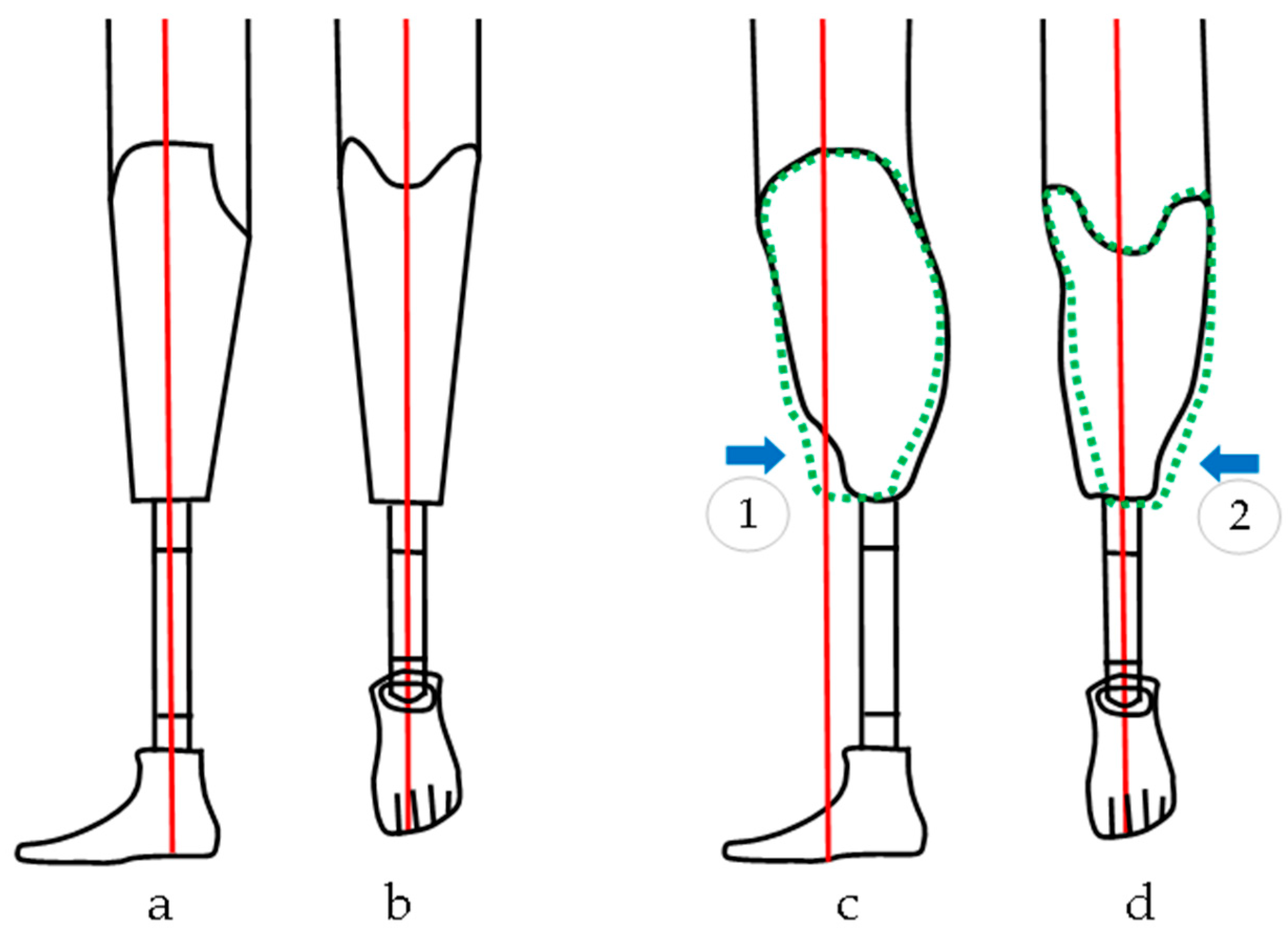
Figure 2.
Vietnamese Transtibial Amputee. (Top Left, L) Wearing a Conventional Prosthesis (CVP). (Top Right, R) Wearing a Transtibial MUP Prosthesis. (Bottom) Mercer Patented C-shaped prosthetic foot design (patent ID: US8870968B2).
Figure 2.
Vietnamese Transtibial Amputee. (Top Left, L) Wearing a Conventional Prosthesis (CVP). (Top Right, R) Wearing a Transtibial MUP Prosthesis. (Bottom) Mercer Patented C-shaped prosthetic foot design (patent ID: US8870968B2).

Figure 3.
Noraxon Utium IMU sensor placement. IMUs were attached on the posterior lumbar spine (between L1-L5), posterior pelvis (body area of the sacrum), thigh (frontal and distal half, where there is a lower amount of muscle displacement during gait), and shank (front and slightly medial to be placed along the flattest tibia bone or prosthesis pylon), and a foot (upper foot, slightly below the ankle).
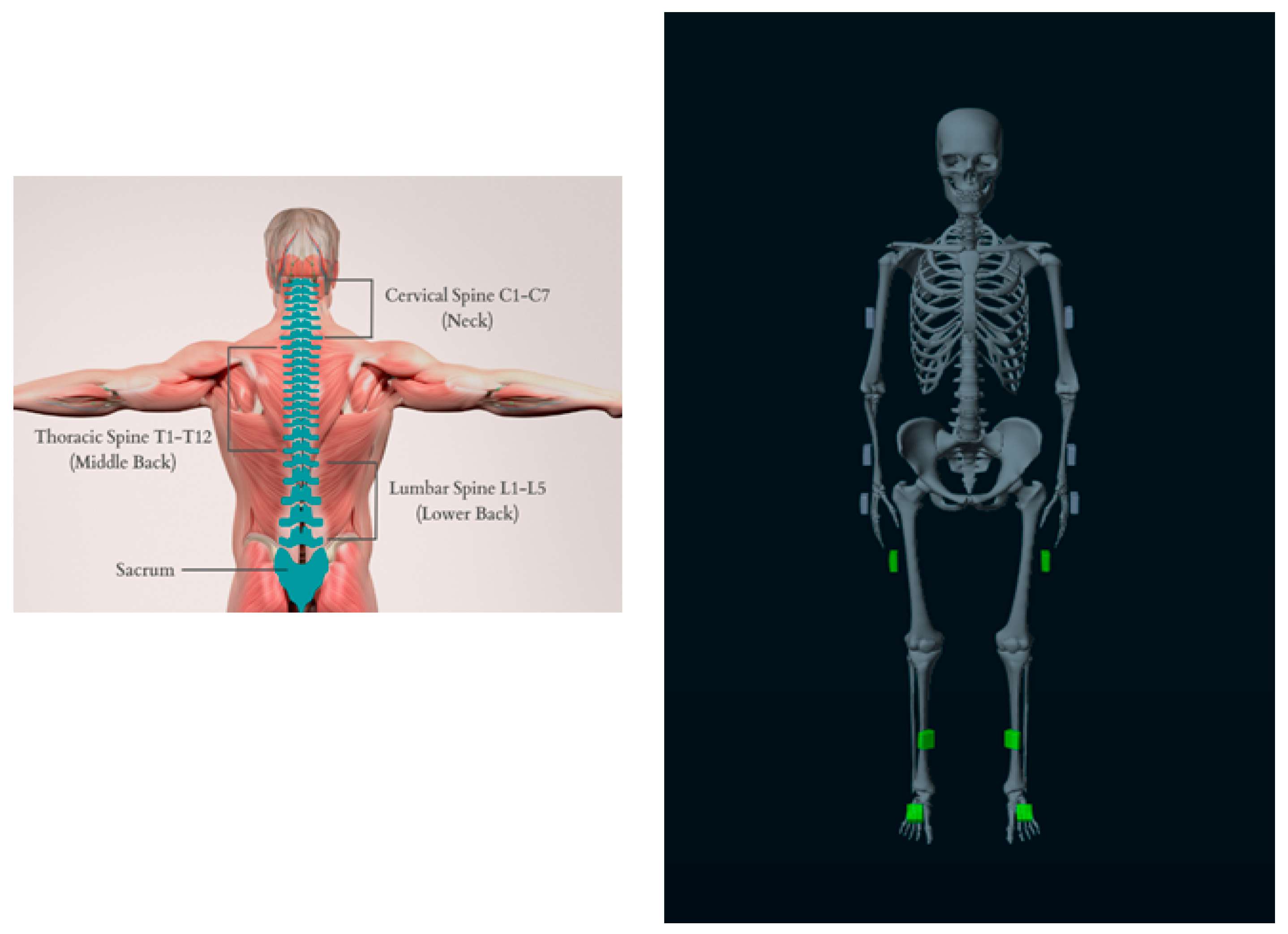
Figure 4.
Pipeline of Kinematic IMU data processing. Data were exported from Noraxon software (MR 3.18) to MATLAB, then segmented into strides based on heel strike (HS) and toe off (TO) events which were derived from sagittal shank angular acceleration or gyro data [21,22]. Finally, peak and symmetry measures were computed.
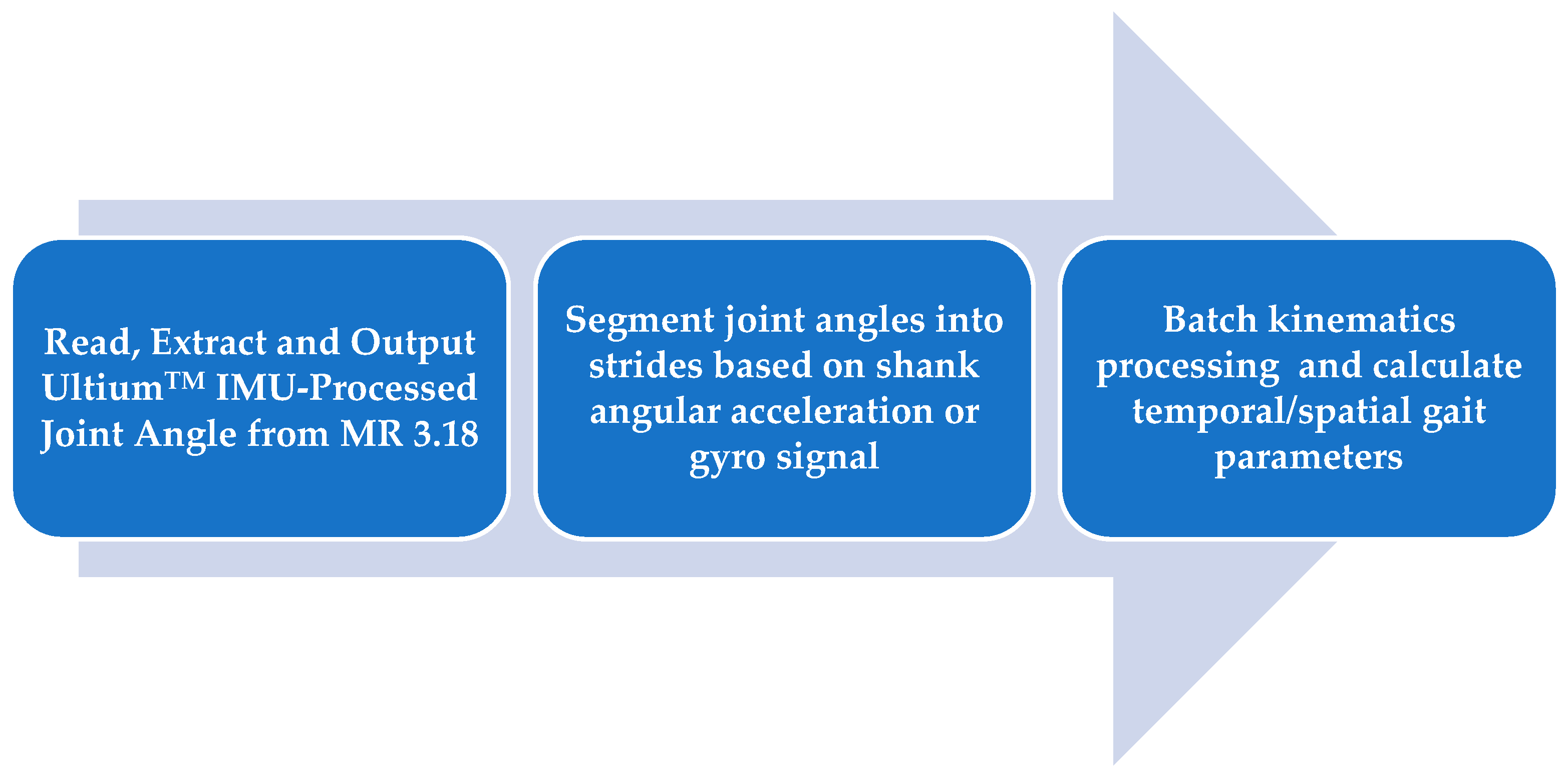
Figure 5.
Interaction Plots of the kinematic Hip and Knee joint angle showing the interaction between prosthetic and intact limb happening in the MUP and CVP groups (a) Maximum Hip Flexion (b) Maximum knee Flexion (c) Knee ROM (d) Hip ROM.
Figure 5.
Interaction Plots of the kinematic Hip and Knee joint angle showing the interaction between prosthetic and intact limb happening in the MUP and CVP groups (a) Maximum Hip Flexion (b) Maximum knee Flexion (c) Knee ROM (d) Hip ROM.
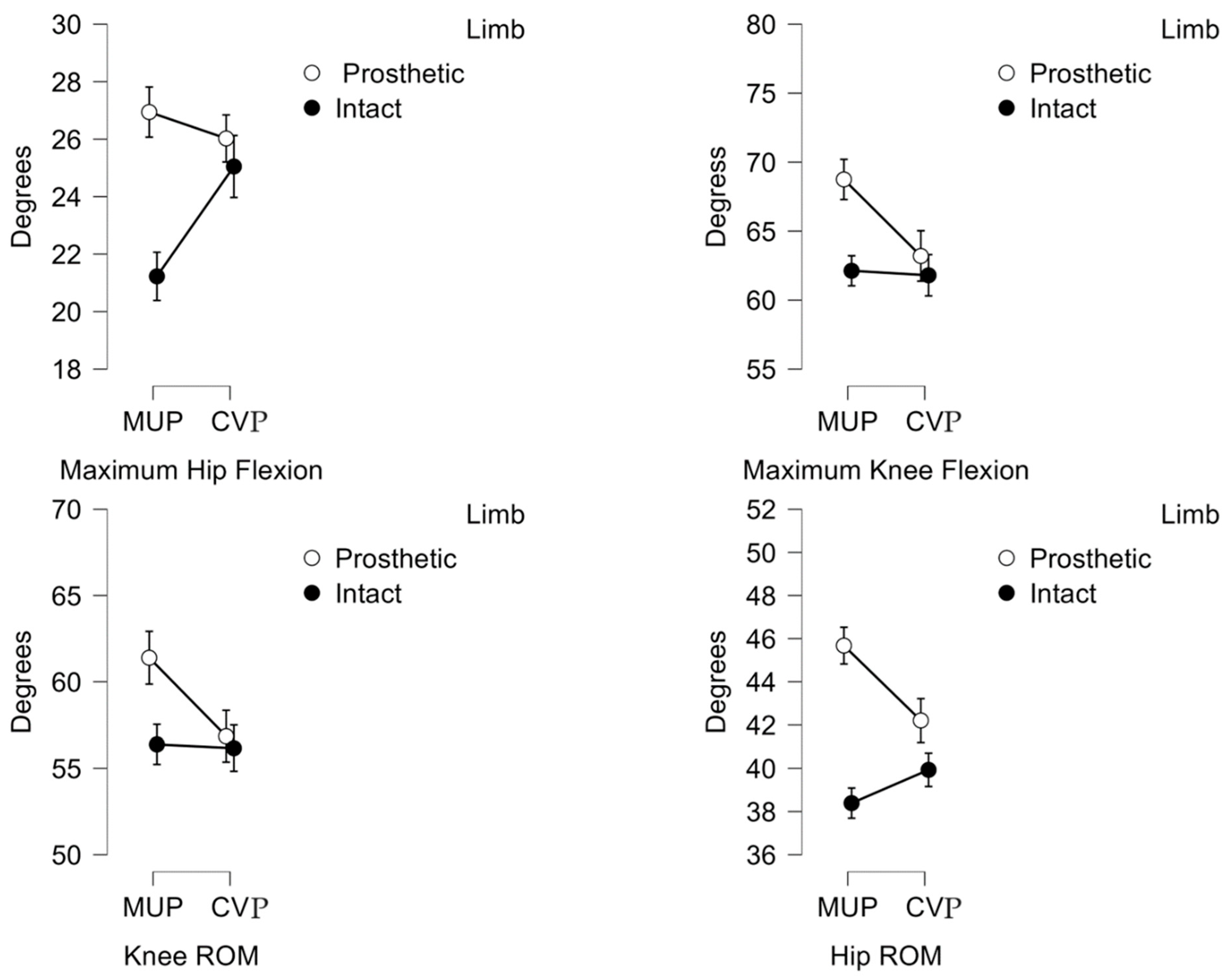
Figure 6.
Plot of average hip, knee and ankle joint angles between intact limb and prosthetic limb. Red (±SD) and blue (±SD) represent Intact and Prosthetic limbs respectively.
Figure 6.
Plot of average hip, knee and ankle joint angles between intact limb and prosthetic limb. Red (±SD) and blue (±SD) represent Intact and Prosthetic limbs respectively.
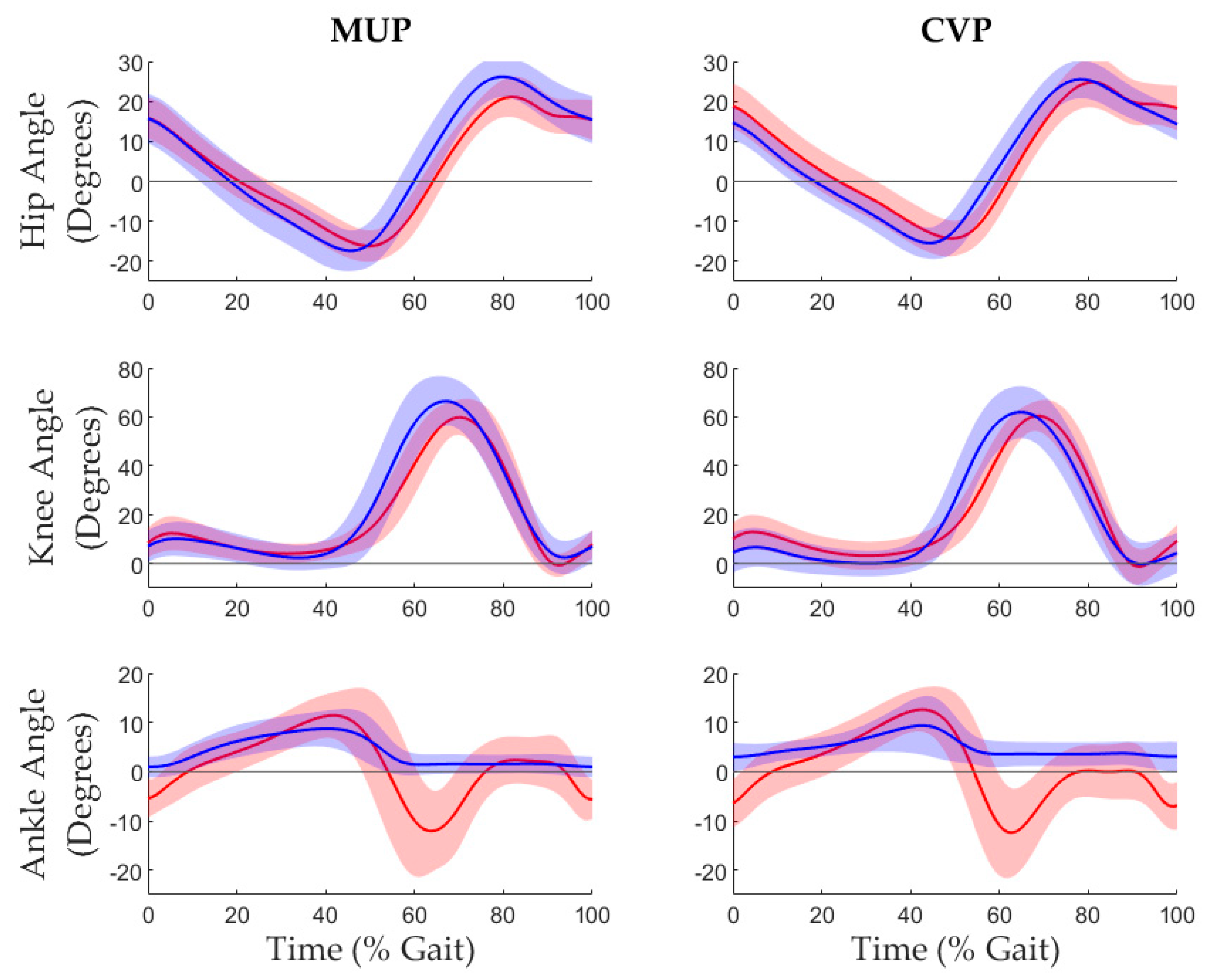

Table 1.
Participant demographics, prosthetic feet mass. In the study setting, participants used a solid SACH foot design for the current conventional device while the Mercer Universal Prostheses utilized the patented C-Shaped design (US patent number: US20110320010A1).
Table 1.
Participant demographics, prosthetic feet mass. In the study setting, participants used a solid SACH foot design for the current conventional device while the Mercer Universal Prostheses utilized the patented C-Shaped design (US patent number: US20110320010A1).
| Sex | 19 Male / 1 Female | |
| Age | 60.4 ± 8.08 year | |
| Height | 1.60 ± 0.07 m | |
| Prosthetic Mass | Conventional (CVP) | 1.55 ± 0.35 kg |
| Mercer Universal (MUP) | 1.31 ± 0.16 kg | |
Table 2.
Spatiotemporal results for transtibial amputees walking with Conventional Prosthesis (CVP) and Mercer Universal Prosthesis (MUP).
Table 2.
Spatiotemporal results for transtibial amputees walking with Conventional Prosthesis (CVP) and Mercer Universal Prosthesis (MUP).
| Descriptive Statistics: Mean (Std) | 2 Factors Repeated ANOVA | ||||||
| MUP | CVP | p-value | |||||
| Prosthetic | Intact | Prosthetic | Intact | Device*Limb | Device | Limb | |
| Stride Time (s) | 1.26 (0.15) | 1.26 (0.15) | 1.24 (0.13) | 1.24 (0.13) | 0.171 | 0.086 | 0.641 |
| Stance Time (s) | 0.65 (0.12) | 0.61 (0.05) | 0.61 (0.09) | 0.63 (0.06) | 0.287 | <0.001** | <0.001** |
| Swing Time (s) | 0.71 (0.14) | 0.55 (0.03) | 0.67 (0.12) | 0.57 (0.03) | 0.785 | 0.003** | <0.001** |
| Speed (m/s) | 0.68 (0.19) | 0.69 (0.20) | 0.72 (0.13) | 0.72 (0.13) | 0.590 | 0.378 | 0.276 |
| Stride Length (m) | 0.86 (0.21) | 0.86 (0.20) | 0.87 (0.10) | 0.89 (0.10) | 0.419 | 0.696 | 0.348 |
| Step Length (m) | 0.44 (0.12) | 0.45 (0.14) | 0.42 (0.10) | 0.48 (0.09) | 0.120 | 0.752 | 0.265 |
Note: * = p < 0.05 and ** = p <0.001.
Table 3.
Kinematic results for transtibial amputees walking with Conventional (CVP) and Mercer Universal (MUP) prostheses.
Table 3.
Kinematic results for transtibial amputees walking with Conventional (CVP) and Mercer Universal (MUP) prostheses.
| Descriptive Statistics: Mean (Std) | 2 Factors Repeated ANOVA | ||||||
| MUP | CVP | p-value | |||||
| Prosthetic | Intact | Prosthetic | Intact | Device*Limb | Device | Limb | |
| Hip Extension (0) | -18.6 (4.1) | -17.1(3.) | -16.1 (3.5) | -14.8 (4.7) | 0.786 | 0.013* | 0.092 |
| Knee Extension (0) | -0.4 (6.2) | -1.4(4.5) | -3.2 (5.8) | -1.5 (7.2) | 0.459 | 0.301 | 0.230 |
| Ankle Plantarflex (0) | 0.3 (2.2) | -17.6 (7.7) | 1.9 (2.9) | -15.1 (7.0) | 0.435 | 0.011* | <0.001** |
| Hip Flexion (0) | 26.9 (4.8) | 21.2 (4.9) | 26.03 (4.5) | 25.1 (6.1) | 0.013 | 0.039* | 0.008 |
| Knee Flexion (0) | 68.4 (9.3) | 62.0(5.8) | 63.2 (9.3) | 61.6 (6.3) | 0.025 | 0.016* | 0.067 |
| Ankle Dorsiflex (0) | 9.3 (4.1) | 12.8 (4.4) | 10.1 (6.2) | 13.7 (4.4) | 0.929 | 0.281 | 0.004* |
| Hip ROM (0) | 45.5 (5.3) | 38.2 (4.1) | 42.1 (6.1) | 39.8 (4.3) | 0.014* | 0.124 | <0.001** |
| Knee ROM (0) | 68.8 (10.6) | 63.1 (5.6) | 66.3 (8.6) | 63.0 (6.5) | 0.033* | 0.024* | 0.168 |
| Ankle ROM (0) | 8.9 (3.5) | 30.3 (6.4) | 8.2 (7.7) | 28.8 (5.7) | 0.675 | 0.305 | <0.001** |
Note: * = p < 0.05 and ** = p <0.001.
Table 4.
Result of Gait Symmetry Index (GSI)– Kinematic (degrees).
| Mean GSI (SEM) |
Paired t-test p < 0.05 |
|||
| MUP | CVP | |||
| Hip Extension (0) | 9.1 (4.9) | 11.1 (7.9) | .780 | |
| Knee Extension (0) | 18.7 (19.4) | 25.1 (23.0) | .806 | |
| Ankle Plantarflexion (0) | -163.4 (46.0) | -267.9 (61.3) | .013* | |
| Hip Flexion (0) | 24.2 (5.5) | 5.2 (5.) | .012* | |
| Knee Flexion (0) | 9.7 (2.8) | 1.7 (4.2) | .026* | |
| Ankle Dorsiflexion (0) | -32.9 (10.9) | -36.4 (12.2) | .738 | |
| Hip ROM (0) | 17.1 (2.9) | 5.1 (3.5) | .014* | |
| Knee ROM (0) | 7.8 (3.6) | 0.6 (4.0) | .044* | |
| Ankle ROM (0) | -109.2 (6.5) | -120.4 (10.3) | .323 | |
Table 5.
Result of Gait Symmetry Index (GSI) – Temporal and Spatial.
| Mean GSI (SEM) |
Paired t-test p < 0.05 |
||
| MUP | CVP | ||
| Stride Duration (s)
Stance Duration (s) Swing Duration (s) Speed (m/s) Stride Length (m) Step Length (m) |
0.5 (0.2) -7.8 (1.4) 9.4 (1.6) -1.2 (1.3) -0.3 (1.4) -0.8 (8.4) |
-0.2 (0.4) -10.2 (1.8) 10.2 (1.8) -0.7 (0.8) -1.6 (0.9) -14.9 (8.0) |
0.120 0.185 0.838 0.747 0.473 0.135 |
Note: %GSI = 0% indicates perfect symmetry. Negative or positive %GSI indicates prosthetic and intact Limb are functioning with asymmetry.
Disclaimer/Publisher’s Note: The statements, opinions and data contained in all publications are solely those of the individual author(s) and contributor(s) and not of MDPI and/or the editor(s). MDPI and/or the editor(s) disclaim responsibility for any injury to people or property resulting from any ideas, methods, instructions or products referred to in the content. |
© 2025 by the authors. Licensee MDPI, Basel, Switzerland. This article is an open access article distributed under the terms and conditions of the Creative Commons Attribution (CC BY) license (http://creativecommons.org/licenses/by/4.0/).
Copyright: This open access article is published under a Creative Commons CC BY 4.0 license, which permit the free download, distribution, and reuse, provided that the author and preprint are cited in any reuse.


