1. Introduction
Additive manufacturing (AM) is a process in which a component is built layer by layer. It encompasses various techniques such as directed energy deposition (DED), which involves focusing energy, like arc, laser, or electron beam, to melt the material and allow precise control over the manufacturing process and the ability to work with metals. Wire-DED enables the creation of highly complex geometries for larger sizes with improved efficiency and material consumption, allowing minimal wastage compared to traditional manufacturing methods.
Over the course of nearly three decades, research has outlined challenges within current additive technologies, particularly in metals. The established technologies with powder AM have various challenges, such as low deposition rate, low surface finish (requires post-processing), powder handling, component size, cost of material and material wastage [
1]. Therefore, to overcome these challenges, the application of welding/cladding is utilized to deposit the material (major) layer by layer, which increases the deposition rate [
2] and the deposition is followed by machining (minor) to furnish the dimensional accuracy and surface finish. This process becomes easier in terms of material handling, the cost of wire is much cheaper than powder, material wastage is significantly low, and the component size can be increased with a suitable motion system holding the deposition system. Thus, the process can be named as Wire Additive Manufacturing for Metals (WAM-M). A synergistic integration of both additive and subtractive processes, leveraging the strengths inherent in each, makes the process Hybrid and researchers started using the term Hybrid Additive Manufacturing [
3,
4,
5] or Hybrid Layered Manufacturing (HLM) [
1,
2,
6]. With a 5-axis motion system, a support-less structure can be realized, which is the core part presented in this paper and adds value to metal-wire AM. Compared to powder AM, support material removal is not required in wire-based hybrid layered manufacturing, but final machining is required to achieve dimensional accuracy and, thus, saves marginal time required for post-processing compared to powder-based AM.
The present study implements hybridization across four levels: processes, energy/heat sources, kinematics, and slicing strategy. At the process level, hybridization involves both additive and subtractive methods. Typically, machining has been conducted as a post-process, following completion of the entire WAAM process. Numerous studies have indicated enhancements in various aspects, such as dimensional accuracy, surface roughness, porosity, hardness, and elongation to failure through hybridization of processes [
7,
8,
9,
10]. Also, a limited number of researchers have experimented with interlayer machining, resulting in improved mechanical properties [
11,
12] and reduced residual stresses [
13].
After every deposited layer, a scalloped surface is formed, and that surface is subsequently addressed through interlayer machining. Machining plays a major role in maintaining Z height accuracy after every deposited layer to assure uniform deposition of subsequent layers and aids in achieving the final product’s dimensional accuracy. Following the near-net shape formation, final machining removes very less amount of excess material.
Energy sources are hybridized based on the accuracy of deposition rates. Metal Inert Gas (MIG) is employed for simple and bulk deposition due to its high deposition and feed rates [
14,
15]. Meanwhile, the laser was chosen for its precision and accuracy in deposition processes.
Kinematics hybridization is tied to the physical setup of deposition. The requirement of 4/5-axis kinematics depends on the complexity and presence of overhanging features in the component's geometry. Simple geometries can be grown planar with 3-axis kinematics, while 5-axis kinematics is required for complex geometries, which helps to eliminate the need for support structures.
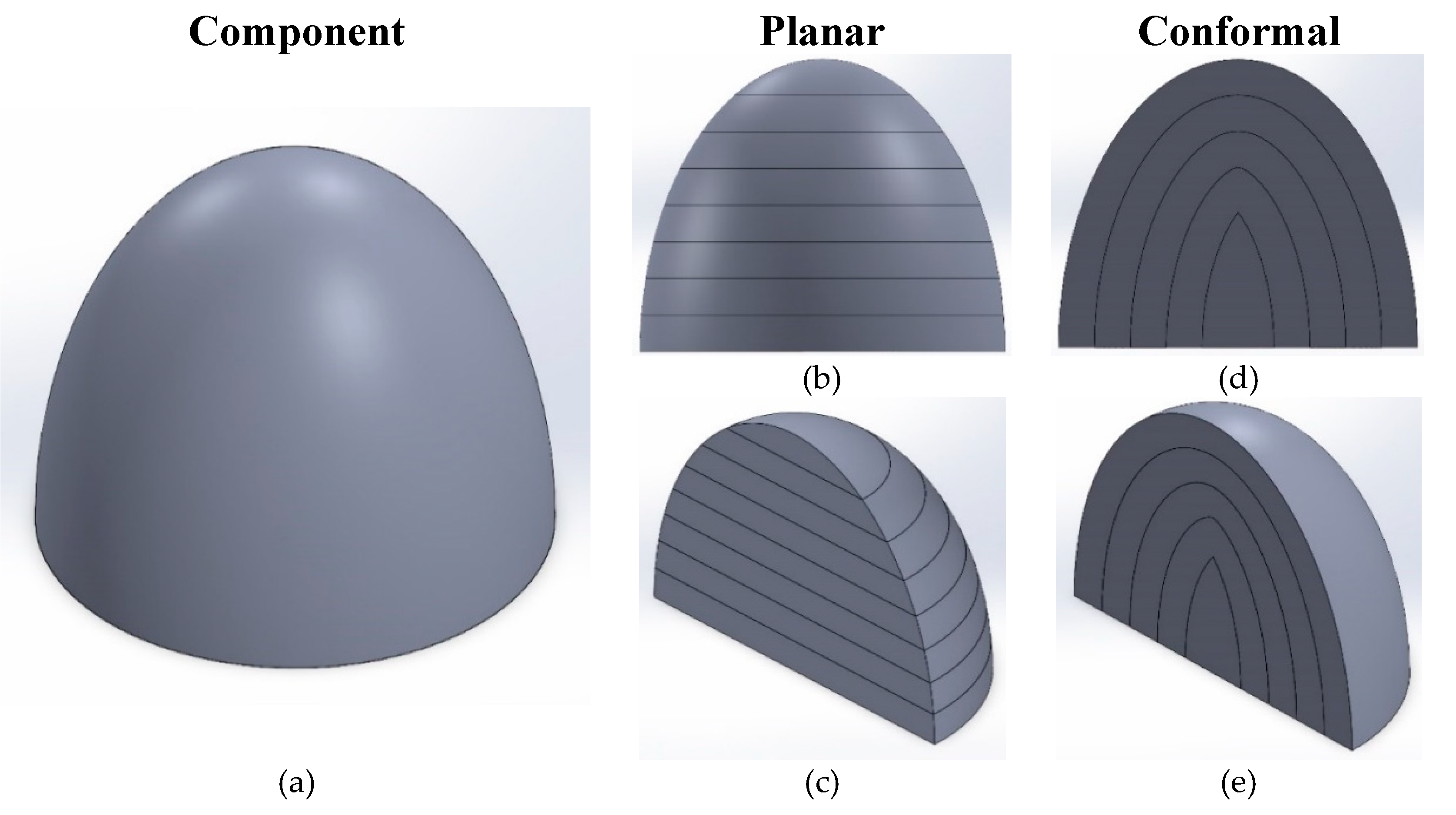
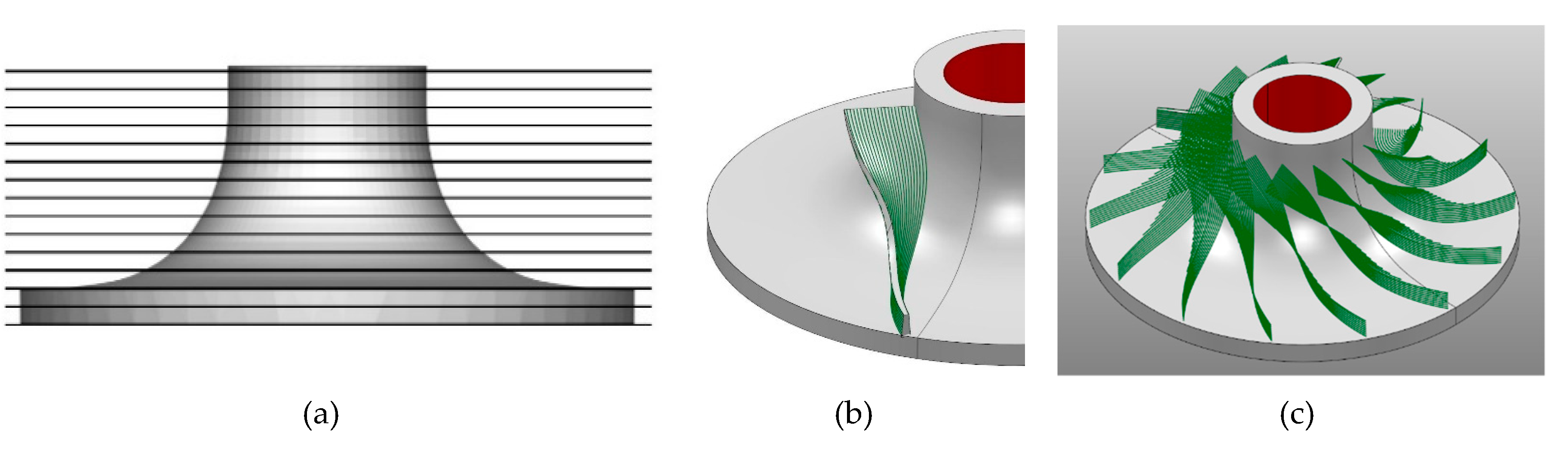
Hybridization in slicing aims to grow components based on their complexity. Planar slicing involves the horizontal slicing of the CAD model (
Figure 1a) with an XY-plane in the vertical direction (Z direction), as depicted in
Figure 1b &
Figure 1c. In contrast, for conformal slicing, the plane by which the CAD model is sliced may or may not be planar.
Figure 1d shows the conformal growth of a hemisphere, where the small originating substrate part is used to slice the entire part by offsetting the surface with a pre-defined deposition layer height shown in
Figure 1e. Examples of conformal growth include natural entities like onions, trees, etc.
To achieve precise positioning of the deposition torch for conformal and planar 5-axis depositions, toolpaths are generated using a double-slicing method, while single slicing is sufficient for 3-axis planar deposition. In the double-slicing approach, each layer is sliced along two XY planes with a 0.1mm offset in the Z direction. The intersections of these planes with the geometry surface create contours, which are then used to construct the toolpath.
According to their manufacturing, there are plenty of complex geometries, such as turbine blades and centrifugal compressor impellers. An impeller has been chosen to investigate the 5-axis deposition with the available setup and to utilise different levels of hybridisation. It is renowned for its complex design, possesses intricate surface characteristics, and has significant economic value in manufacturing.
The conventional method of making an impeller is machining [
16,
17], which leads to the wastage of material and consumes a high amount of time due to roughing and finishing operations and casting [
18] which is a time-consuming process because of pre and post-processing requirements. There are few research available with selective laser melting technology for manufacturing impellers [
19] where different orientations were studied to perform the fabrication. However, the surface roughness was not at par. These methods have various challenges; therefore, the wire-based hybrid layered manufacturing technique has been utilised in this study for the manufacturing of impellers with different strategies, which are presented in this paper.
2. Materials and Methods
2.1. Materials
In all the cases presented in this paper utilizing both energy sources, the material used was mild steel (Grade ER 70S-6) with a diameter of 1.2 mm. The composition of the material is provided in
Table 1. The initial deposition involved a 20 mm thick and 180 mm diameter circular substrate plate of mild steel with the same composition as wire.
2.2. Approach for Deposition
Two instances of experimentation have been conducted for the manufacturing of Impeller, employing varying hybridization approaches. In one scenario, the deposition was executed using a 5-axis planar double-slicing method, while the machining was carried out in a planar 3-axis fashion. Additionally, the cladding process employs Cold Metal Transfer (CMT) - TransPlus Synergic (TPS) 2700 (Fronius, Austria-based company) as a power source. It involves slicing through a planar double-slicing method, allowing the machine to execute simultaneous 5-axis motion during deposition. Also, a combination of planar and conformal slicing was applied in another case study. Here, the hub of an impeller underwent planar 3-axis slicing, followed by deposition using the MIG power source and subsequent interlayer machining. Meanwhile, the blades were sliced conformally, facilitating deposition with a Laser power source of 4kW by Laserline LDF 4000 30 (Laserline, Germany-based company); followed by interlayer machining of the blades in the same conformal fashion.
2.3. Fixture
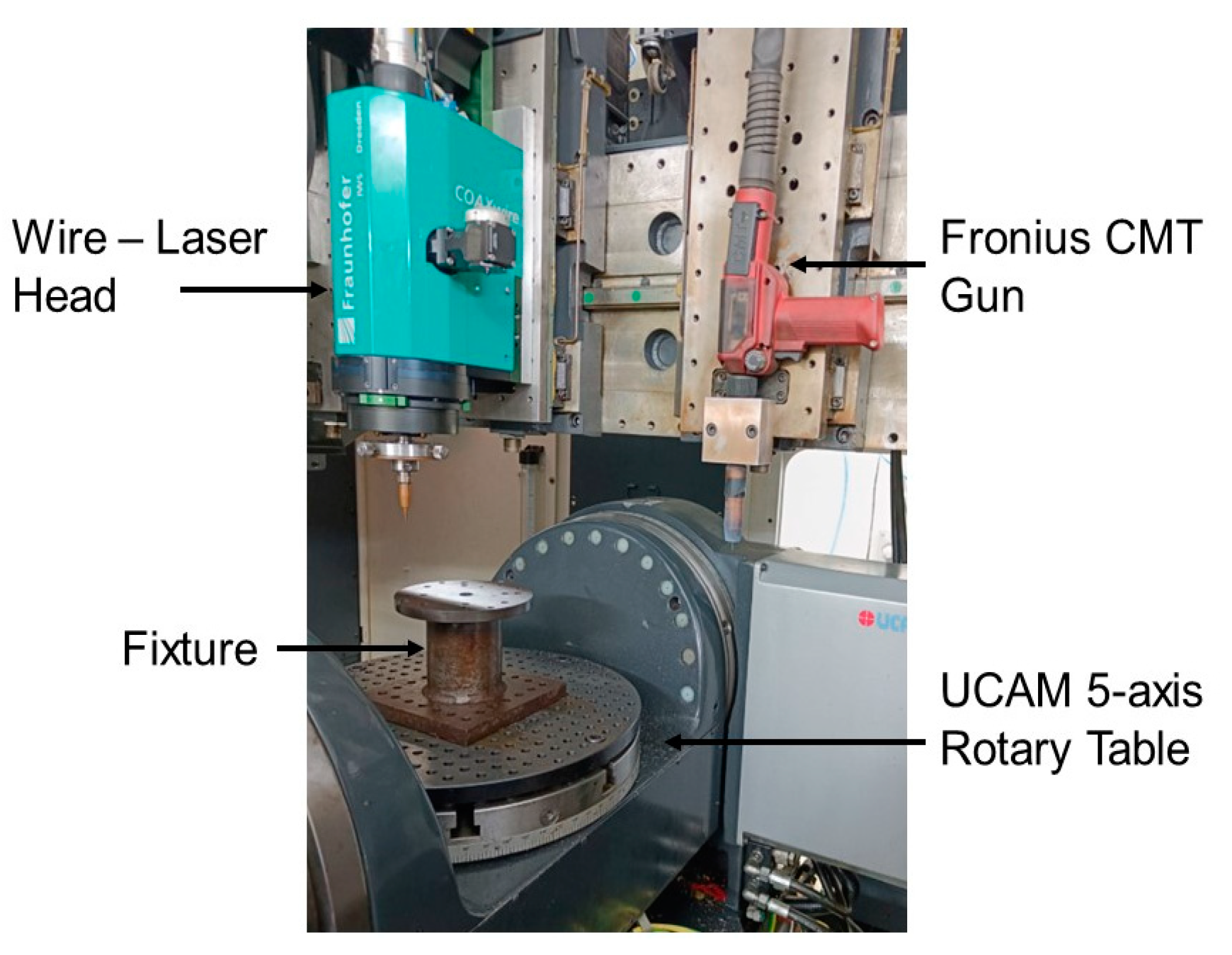
An extended fixture was required to avoid collision with the Laser head and MIG torch, which are mounted at an offset distance of the multi-platform 5-axis CNC machine, and the setup is shown in
Figure 2. The maximum tilt of the rotary table is ±110° symmetrically in both directions, whereas the rotation about the Z-axis is 360°.
2.4. Test Methods
Prior to actual deposition, parameters were optimized to achieve suitable bead thickness and layer height through single-bead, multi-bead, and multi-pass experiments, and the selected process parameters are detailed in
Table 2.
While the MIG source has a synergic wire feeding system that is linked to the current, the laser source allows for independent adjustment of the wire feed rate due to its separate wire feeding setup. As the MIG has a higher deposition rate, the stepover (distance between two consecutive parallel beads) was kept higher than the Laser. Using this basic experimentation, the Hardness and UTS values were carried out for better comparison between the processes. The INNOVATEST Model 412D was employed for measuring microhardness. Samples underwent grinding and polishing with SiC emery papers up to 2500 grit. A load of 100g was applied for a dwell time of 10 seconds. Each reported value represents the average of three measurements taken along the same horizontal line. Also, Micro-tensile samples were machined from build surfaces in the build direction, with a gauge length of 15 mm and thickness of 2 mm [
21].
Tensile testing was conducted using a Tinius Olsen (Model H25KS) machine at room temperature. Results are the averages of three tensile tests. All samples were cut via Wire-Electrical Discharge Machining to meet the miniature-tensile specimen size requirements. Loading conditions included a speed of 0.5 mm/min and a gauge length of 5.0 mm.
2.5. Slicing and Deposition Methodology
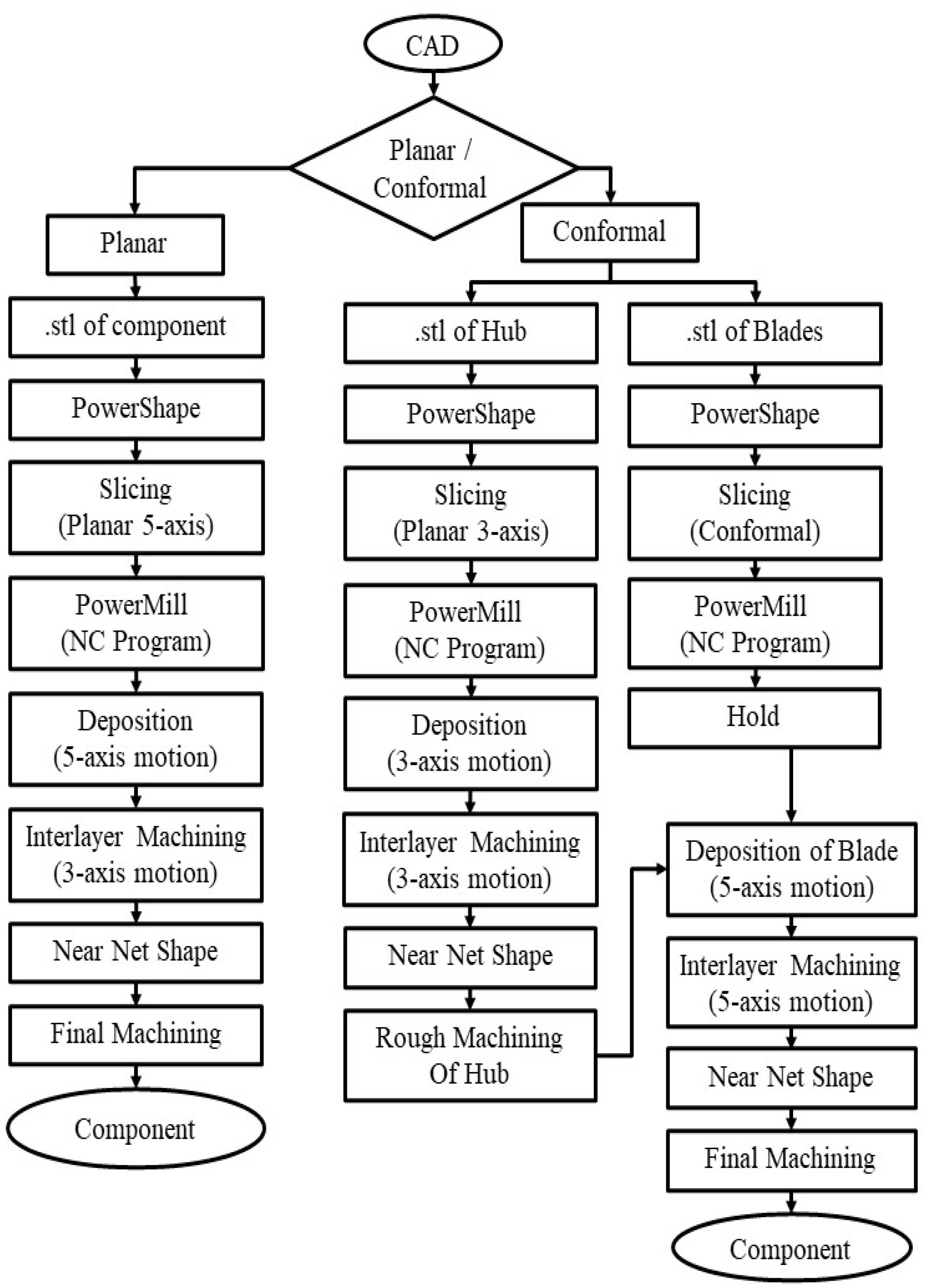
In the process of planar 5-axis deposition, a method known as the double-slicing strategy was implemented. Initially, the CAD model was created using SolidWorks (CAD Software) and saved in .stl format. Subsequently, this CAD file was imported into PowerShape software, which is integrated with an in-house developed API called GatiNirman, which is also integrated with PowerMill software, a CAM package. The operation flowchart is shown in
Figure 3.
Within the GatiNirman, parameters related to slicing and toolpath, such as layer height, kinematics (3/5-axis), machining allowance, stepover and travel speed, were defined. The component was sliced in PowerShape with the assistance of GatiNirman, which sequentially executed the required commands according to the predefined data.
In PowerShape, the bottommost XY plane is selected, creating a new rectangular plane that extends 5 mm in the X and Y axes (bi-directional) from the original component dimensions. An additional support plane, positioned 0.1 mm above, is generated. These planes are offset by the specified layer thickness to intersect with external and internal surfaces. Contours were extracted at the interface between these planes and surfaces, then transferred to PowerMill and saved individually by layer numbers. Each layer has two contours: the bottom contour serves as a toolpath curve during creation, while the upper contour acts as a guide curve, as depicted in
Figure 4.
The toolpath is generated using these two curves and various strategies available in the PowerMill. Subsequently, all the toolpaths are transferred to the Siemens 840Dsl CNC controller, and the deposition process commences for the initial layer, utilizing the configuration of the 5-axis table illustrated in
Table 2. To ensure Z accuracy, 3-axis flat milling is performed, concluding the fabrication of the first layer. A layer height of 1.5 mm was maintained throughout the manufacturing as optimised with initial multi-pass trials.
Upon examination of the Impeller’s complexity, it becomes evident that the component can be divided into two distinct parts: the Hub and the Blade. Each part can be manufactured using different slicing, deposition, energy source, and kinematic strategies, leveraging their respective advantages. A novel process of slicing and deposition has been introduced, with the overall steps outlined in
Figure 3 called Conformal Slicing.
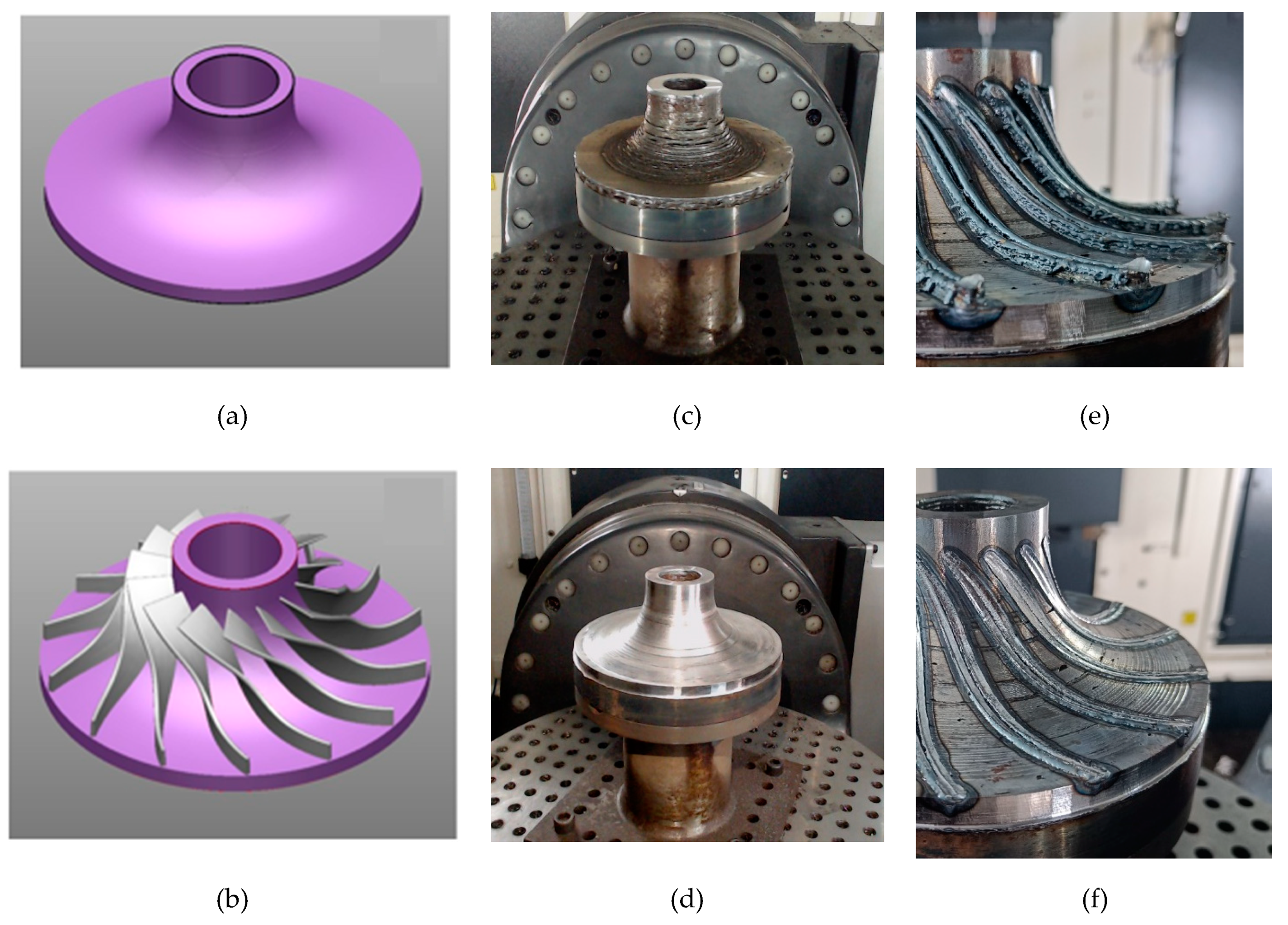
The CAD model of Hub shown in
Figure 6a was imported into the PowerShape, where the component underwent planar 3-axis slicing facilitated by the GatiNirman. During slicing, only one plane is created at the bottom of the hub, simplifying the process compared to double slicing. In 3-axis slicing, a single plane suffices since the tool remains in a vertical position throughout. The newly generated plane is offset to the maximum height at a predefined layer height of 1.5 mm, as shown in
Figure 5a. This creates contours at the intersection of the hub's inner hollow and outer curved surfaces with the offset planes, followed by the generation of the toolpath and NC program, likely as the double-slicing method.
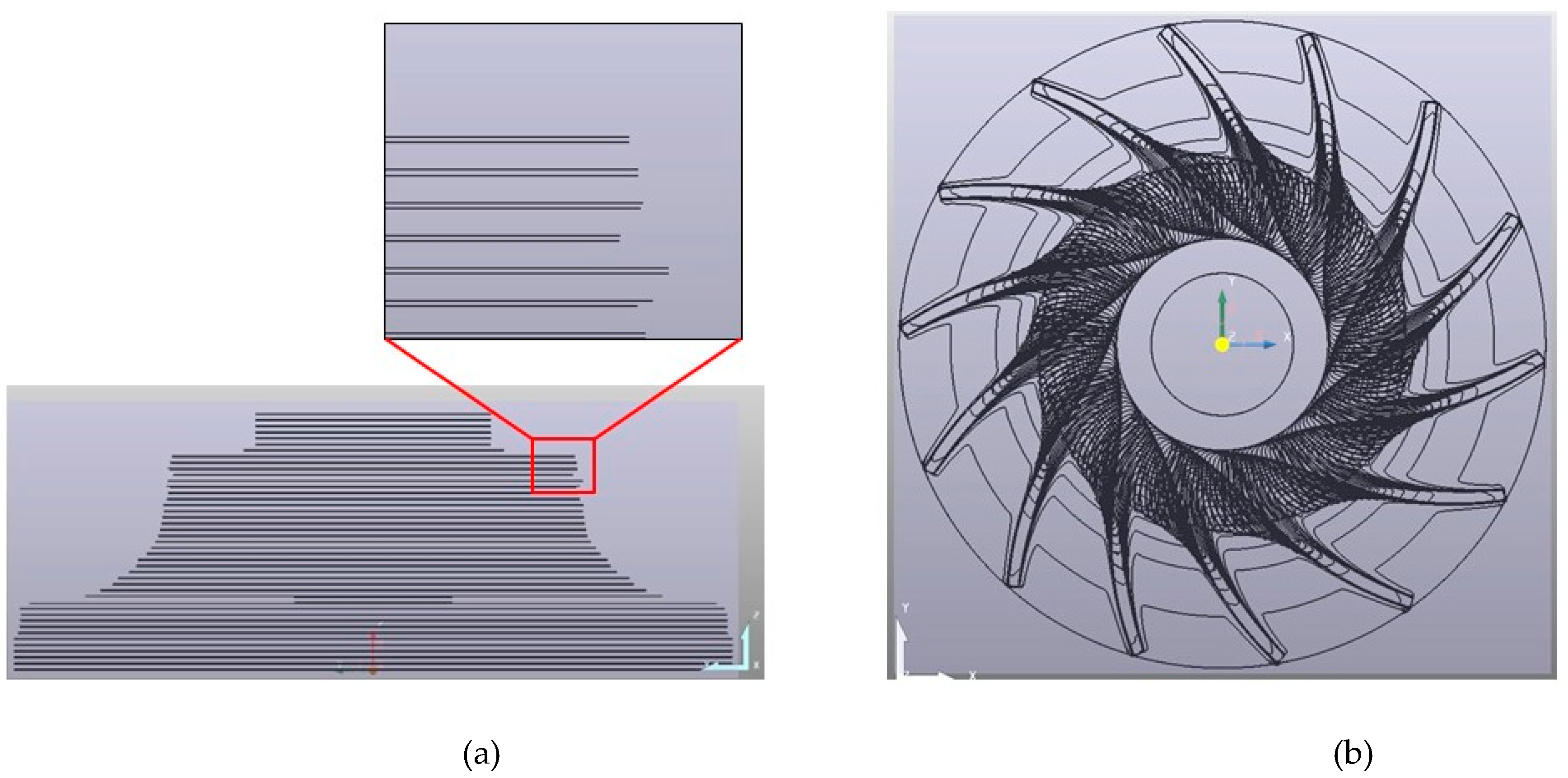
A single blade was selected to generate toolpaths for the blades, and the hub's surface was imported into PowerShape. During conformal slicing, it's crucial to choose the surface for the component's growth. Here, the outer surface of the hub was chosen and offset by 1 mm, aligning with the layer height, despite the blade's base width exceeding 2 mm, a single bead deposited with the selected parameters measured a width and height of around 2 mm and 1.3 mm respectively. Consequently, both the right and left surfaces of the blades were considered when extracting contours at the intersection of the offset surface and the blade surfaces, as shown in
Figure 5b. A series of offset surfaces enabled contour creation for the entire blade height. These contours were then transferred to PowerMill and saved as individual patterns for the right and left surfaces on the same slice.
For each blade at a specific slice, three distinct toolpaths were generated: one for the right surface, one for the left surface, and the third to fill the gap between these two beads using PowerMill's toolpath strategies. Subsequently, with the help of PowerMill, a transformation into a circular pattern over the hub surface was executed to create 14 blades evenly spaced apart.
Figure 5c displays only the middle toolpath, illustrating the blade growth over the hub. The green-coloured curves represent the toolpath for filling the area between two surfaces.
The NC programs for hub toolpaths were fed into the CNC controller for deposition using the MIG setup. Layer-by-layer growth was conducted with intermittent machining to maintain the layer height until reaching the maximum Z-height, as shown in
Figure 6c. Following this, machining of the hub was performed to ensure accuracy for blade deposition, as depicted in
Figure 6d.
Subsequently, the Laser-wire setup was engaged to deposit the blades conformally with 5-axis kinematics, utilizing the NC program generated by toolpaths for blade deposition. After the first layer of deposition, the toolpath for the second layer was activated for interlayer machining, maintaining a 1 mm height with an 8mm ball nose end mill. Different work offsets and transformation tables were created for various deposition techniques and machining processes. The same toolpath used for machining was employed for the deposition of the second layer. This process continued until the completion of overall blade deposition.
Layer-wise deposition was conducted to prevent collisions between the deposition head and previously deposited parts.
Figure 6e illustrates the as-deposited bead of only the right and left surface toolpaths, followed by the middle. Subsequent machining of all the beads with the second layer was performed with a 1mm layer height, as shown in
Figure 6f.
The duration of each operation involved in manufacturing the impeller has been meticulously documented in both scenarios. Additionally, to facilitate comparison, machining from a cylindrical block, one of the methods employed in impeller production, was taken into account. Using PowerMill strategies, the time required for roughing and finishing operations was calculated. The parameters chosen for this process are outlined in
Table 3. Parameters for hub and blade finishing in additively manufactured impellers mirror those utilized in machining operations.
3. Results and Discussion
In the planar double-slicing approach, deposition was done with an MIG source and to ensure the Z-accuracy of the deposition, machining was performed after each layer. Also, in the conformal case, the hub was deposited with MIG. The 1.5 mm layer height was maintained by considering the advantage of MIG, which is a higher deposition rate. Variations were observed during deposition in the as-deposited layer height, ranging from 1.6 mm to 1.9 mm. On the other hand, blades were deposited conformally with a Laser source. The height maintained with machining was 1mm, where the deposition varies between 1.1 mm and 1.24 mm within a single layer.
3.1. Process Hybridization
This process hybridization study investigates the effects of interlayer machining on the processing-structure-properties relationships in WAAM of mild steel ER70S-R, comparing it with the continuous deposition process (without interlayer machining). Due to the predominantly one-way heat flow observed in metal AM processes, along with the re-melting of the previous layer or substrate, and the increased thermal gradient within the molten pool, it promotes epitaxial nucleation and growth [
22,
23]. This phenomenon leads to the formation of coarse columnar grains exhibiting a preferred crystallographic orientation, such grain structure can result in anisotropic properties [
24,
25]. The introduction of interlayer machining between the deposition of layers inhibits epitaxial grain growth and contributes to grain refinement through deformation [
11]. This refinement of grains enhances microhardness and ultimate tensile strength in accordance with the Hall-Petch equation, which states that grain size is inversely proportional to hardness and yield strength. The effect of interlayer machining on hardness and tensile stress is presented in
Table 4.
3.2. Energy Hybridization
This study was carried out to combine the benefits and eliminate disadvantages of Laser and MIG power sources and compare the result with the component built with the MIG source alone with the component built with the application of both Laser and MIG.
For the deposition using the MIG source, the bead width and height were around 2.4 and 1.9 mm, respectively, while using multi-pass experiments with the same parameters, the height measured was in the range of 1.8 to 2.2 mm. Meanwhile, with laser deposition, the deposited single bead was around 1.3 mm in width and 1.2 mm in height when deposited using the given deposition parameters in
Table 2.
The conformal deposition technique of the impeller was divided into two features, i.e., first as the simple non-overhanging geometry hub and the second feature as the blade, which is complex and overhanging in nature. As the blade is a thin feature with a complex geometry, the laser shows better deposition capabilities in a conformally deposited impeller. Whereas the hub was deposited comparatively faster with MIG source, where a high deposition rate plays a major role. Laser demonstrates precise addition of the material with bead geometries in the conformal deposition of the impeller. As shown in
Table 5 and
Table 6, the comparison in terms of time-saving and material-saving favoured the conformal deposition in which both welding sources were used.
3.3. Kinematic and Slicing Hybridization
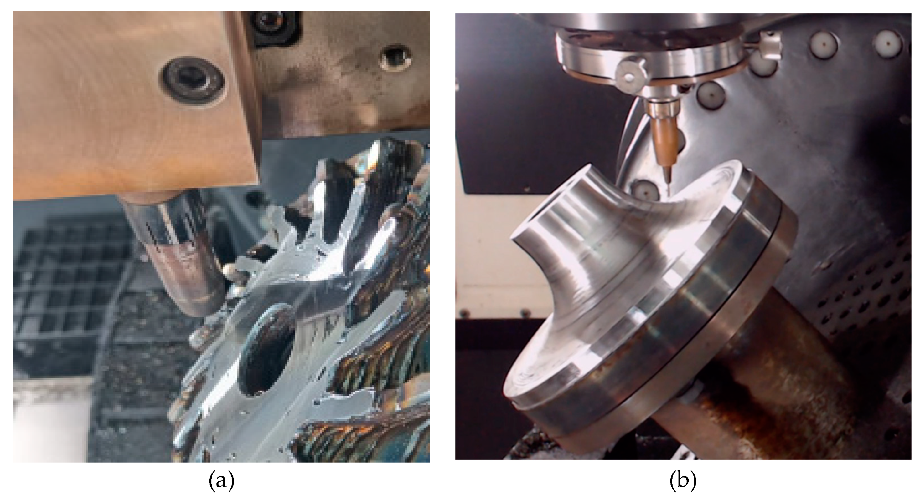
The overhanging feature requires support material for the dimensional accuracy of the component while depositing with 3-axis kinematics. It is eliminated with the 5-axis kinematics with the help of a different slicing strategy than a conventional slicing strategy. Elimination of support material gives another advantage, which is material saving. While comparing the planar slicing and conformal slicing of an impeller, the probability of collision of the MIG torch and the deposited layer was very high at the corners as shown in
Figure 7a. However, it was eliminated while depositing the blade with conformal slicing and 5-axis kinematics because the torch is always perpendicular to the deposition surface, which is the hub, as shown in
Figure 7b.
Conformal slicing is an advanced technique in additive manufacturing that generates layers conforming to the part's curved geometry. Unlike traditional planar slicing, which divides the model into flat horizontal planes, conformal slicing aligns the layers with the natural contours of the design. This approach minimizes stair-stepping effects, improves surface quality, and enhances the structural integrity of complex or freeform parts.
3.4. Time and material wastage comparison
Time was meticulously recorded throughout the deposition, interlayer machining, and final machining processes in both case studies of the HLM process and mentioned in
Table 5. Using the same machining parameters as mentioned in
Table 3, the time needed to manufacture the impeller with machining processes was determined by applying PowerMill strategies. Initially, a cylindrical block with a diameter of 180mm and a height of 65mm was selected. It was programmed for manufacturing using the best suitable parameters for rough machining based on Londhe et al. [
26], along with a proven finishing program used for other impellers. While comparing these studies, setup time and material handling time were disregarded in calculations.
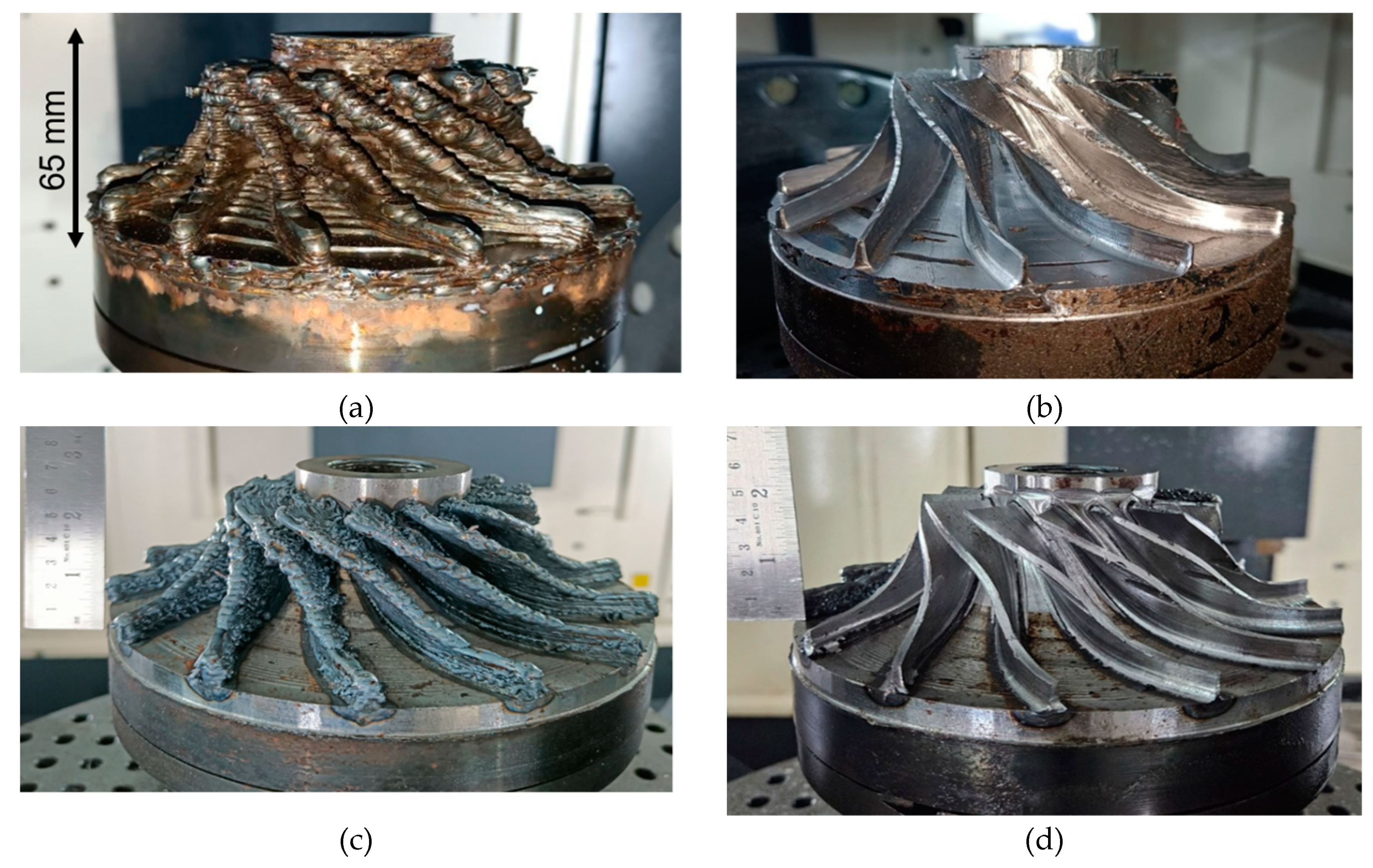
This approach achieved a near-net shape, as shown in
Figure 8a for the planar double-slicing strategy and
Figure 8c for the conformal strategy. The blade width was measured for both impeller cases, leading to the creation of finishing programs, as roughing operation was not required. Due to MIG's higher deposition rate, the blade width measured 9.1 mm, while on conformally deposited blades, it measured 6.5 mm, matching the required dimension of 4.9 mm at that point. Measurements at various blade points revealed a 2 mm variation on both sides from the actual required dimensions, whereas, with laser, the variation was only 0.8 mm on both surfaces—finished components after planar and conformal are shown in
Figure 8b and
Figure 8d, respectively.
During these calculations, a study on material wastage was conducted for both additive and subtractive cases. As indicated in
Table 6, the material wastage for impellers manufactured using machining was 74.07%. For additively manufactured components, the wastage was approximately 13% and 9.3% in planar and conformal cases, respectively.
This hybrid approach significantly reduced both manufacturing time and material waste, providing an efficient, precise, and cost-effective solution for producing complex metal components, such as impellers. The conformal strategy demonstrated marked improvements over traditional machining methods and non-hybrid AM processes, highlighting the advantages of integrating hybridization in metal manufacturing.
4. Conclusions
This study explored the hybridization of metal-wire additive manufacturing processes using a 5-axis impeller case study to optimize the production of complex geometries. Traditional metal AM methods face low deposition rates and material wastage-related challenges. Hybrid manufacturing was employed to address these challenges, combining additive and subtractive processes, using different energy sources like MIG and Laser, kinematics (up to 5-axis), and slicing techniques (planar and conformal). The methodology involved manufacturing the impeller using these hybrid techniques, with MIG and Laser energy sources tailored to different impeller parts for optimal results. The blades required high precision and were conformally sliced and deposited with Laser, while the bulkier hub used the faster MIG deposition. This is compared with another method of manufacturing without involving the hybridization of the slicing technique and energy source with 5-axis motion.
Key advantages of hybrid approach include:
Process Hybridization: Interlayer machining improved mechanical properties, increasing microhardness from 152 HV to 178 HV and tensile strength from 444 MPa to 487 MPa by refining the grain structure. This also enhanced dimensional accuracy and reduced residual stress, which is crucial for complex parts like the impeller.
Energy Source Hybridization: The MIG source was utilized for fast and bulk deposition of the hub, where the Laser provided precise control over the intricate blade geometry. These sources combined ensured faster production with improved surface quality.
Kinematics Hybridization: The use of 5-axis kinematics eliminated the need for support structures, particularly in complex overhanging features, reducing material use and improving process efficiency.
Slicing Technique Hybridization: Conformal slicing, applied to the blades, achieved better alignment with the natural shape of the component, significantly improving dimensional accuracy (blade deviation reduced to 0.8 mm) compared to planar slicing (2 mm deviation).
This hybrid approach led to a substantial reduction in both time and material waste, with the conformal strategy reducing total manufacturing time to 792 minutes and material wastage to 9.3%, compared to 74.07% in traditional machining. The findings demonstrate that hybrid manufacturing offers a more efficient, accurate, and cost-effective solution for producing complex metal components like impellers, enhancing the overall capabilities of metal-wire AM.
References
- Karunakaran, K.P.; Kamal Gupta, N.; Kumar Patel, A.; Rakeshkumar, K.; Ganesan, G.; Siddhartha; Sealy, M.; Bernard, A. Multi-Station Multi-Axis Hybrid Layered Manufacturing (MSMA-HLM). Manuf Lett 2022, 33, 630–639. [CrossRef]
- Gupta, N.K.; Ganesan, G.; Siddhartha, S.; Karade, S.R.; Singh, S.D.; Karunakaran, K.P. A Dual-Side Deposition Technique to Mitigate Deformation in Wire Arc Additive Manufacturing. Transactions of the Indian Institute of Metals 2024, 77, 3425–3434. [CrossRef]
- Sealy, M.P.; Madireddy, G.; Williams, R.E.; Rao, P.; Toursangsaraki, M. Hybrid Processes in Additive Manufacturing. Journal of Manufacturing Science and Engineering, Transactions of the ASME 2018, 140. [CrossRef]
- Flynn, J.M.; Shokrani, A.; Newman, S.T.; Dhokia, V. Hybrid Additive and Subtractive Machine Tools - Research and Industrial Developments. International Journal of Machine Tools and Manufacture 2016, 101, 79–101. [CrossRef]
- Strong, D.; Sirichakwal, I.; Manogharan, G.P.; Wakefield, T. Current State and Potential of Additive - Hybrid Manufacturing for Metal Parts. Rapid Prototyping Journal 2017, 23, 577–588. [CrossRef]
- Suryakumar, S.; Karunakaran, K.P.; Bernard, A.; Chandrasekhar, U.; Raghavender, N.; Sharma, D. Weld Bead Modeling and Process Optimization in Hybrid Layered Manufacturing. CAD Computer Aided Design 2011, 43, 331–344. [CrossRef]
- Park, S.H.; Son, S.J.; Lee, S.B.; Yu, J.H.; Ahn, S.J.; Choi, Y.S. Surface Machining Effect on Material Behavior of Additive Manufactured SUS 316L. Journal of Materials Research and Technology 2021, 13, 38–47. [CrossRef]
- Kaynak, Y.; Kitay, O. Porosity, Surface Quality, Microhardness and Microstructure of Selective Laser Melted 316l Stainless Steel Resulting from Finish Machining. Journal of Manufacturing and Materials Processing 2018, 2. [CrossRef]
- Yang, Y.; Gong, Y.; Qu, S.; Yin, G.; Liang, C.; Li, P. Additive and Subtractive Hybrid Manufacturing (ASHM) of 316L Stainless Steel: Single-Track Specimens, Microstructure, and Mechanical Properties. Jom 2021, 73, 759–769. [CrossRef]
- Xinhong, X.; Haiou, Z.; Guilan, W.; Guoxian, W. Hybrid Plasma Deposition and Milling for an Aeroengine Double Helix Integral Impeller Made of Superalloy. Robotics and Computer-Integrated Manufacturing 2010, 26, 291–295. [CrossRef]
- Chen, C.; Feng, T.; Zhang, Y.; Ren, B.; Hao wang; Zhao, X. Improvement of Microstructure and Mechanical Properties of TC4 Titanium Alloy GTAW Based Wire Arc Additive Manufacturing by Using Interpass Milling. Journal of Materials Research and Technology 2023, 27, 1428–1445. [CrossRef]
- Karunakaran, R.; Sotelo, L.D.; Maharaja, H.; Nez, C.; Ramoni, M.; Halliday, S.; Mishra, S.; Karunakaran, K.P.; Turner, J.A.; Sealy, M.P. Increased Ductility of Ti-6Al-4V by Interlayer Milling during Directed Energy Deposition. Additive Manufacturing 2023, 78, 103818. [CrossRef]
- Sadeh, S.; Mathews, R.; Zhang, R.; Sunny, S.; Marais, D.; Venter, A.M.; Li, W.; Malik, A. Interlayer Machining Effects on Microstructure and Residual Stress in Directed Energy Deposition of Stainless Steel 316L. Journal of Manufacturing Processes 2023, 94, 69–78. [CrossRef]
- Ivántabernero; Paskual, A.; Álvarez, P.; Suárez, A. Study on Arc Welding Processes for High Deposition Rate Additive Manufacturing. In Proceedings of the Procedia CIRP; Elsevier B.V., 2018; Vol. 68, pp. 358–362.
- Gupta, N.K.; Ganesan, G.; Siddhartha, S.; Karade, S.R.; Paul, A.K.; Dubey, S.; Ely, R.H.; Karunakaran, K.P. In Situ Pre-Heating in Wire Arc Additive Manufacturing: Design, Development, and Experimental Investigation on Residual Stresses and Metallurgical and Mechanical Properties. J Mater Eng Perform 2024. [CrossRef]
- Chuang, L.C.; Young, H.T. Integrated Rough Machining Methodology for Centrifugal Impeller Manufacturing. International Journal of Advanced Manufacturing Technology 2007, 34, 1062–1071. [CrossRef]
- Fan, H.Z.; Wang, W.; Xi, G. A Novel Five-Axis Rough Machining Method for Efficient Manufacturing of Centrifugal Impeller with Free-Form Blades. International Journal of Advanced Manufacturing Technology 2013, 68, 1219–1229. [CrossRef]
- Zhu, Q.; Midson, S.P.; Chng, W.M.; Atkinson, H. V. Casting and Heat Treatment of Turbocharger Impellers Thixocast from Alloy 201. Solid State Phenomena 2013, 192–193, 556–561. [CrossRef]
- Adiaconitei, A.; Vintila, I.S.; Mihalache, R.; Paraschiv, A.; Frigioescu, T.; Vladut, M.; Pambaguian, L. A Study on Using the Additive Manufacturing Process for the Development of a Closed Pump Impeller for Mechanically Pumped Fluid Loop Systems. Materials 2021, 14, 1–17. [CrossRef]
- Gupta, Neel Kamal, G, Ganesan, Siddhartha, Karade Shahu, Mehta, Avinash Kumar, KP, Karunakaran Effect of Multiple Technologies on Minimizing the Residual Stresses in Additive Manufacturing. In Proceedings of the ICRS 11 - The 11th International Conference of Residual Stresses, SF2M; IJL, Mar 2022, Nancy, France.; 2022; Vol. hal-040150.
- Jacob, K.; Yadav, D.; Dixit, S.; Hohenwarter, A.; Jaya, B.N. High Pressure Torsion Processing of Maraging Steel 250: Microstructure and Mechanical Behaviour Evolution. Materials Science and Engineering: A 2021, 802, 140665. [CrossRef]
- Farias, F.W.C.; da Cruz Payão Filho, J.; Moraes e Oliveira, V.H.P. Prediction of the Interpass Temperature of a Wire Arc Additive Manufactured Wall: FEM Simulations and Artificial Neural Network. Additive Manufacturing 2021, 48. [CrossRef]
- Paul, S.; Liu, J.; Strayer, S.T.; Zhao, Y.; Sridar, S.; Klecka, M.A.; Xiong, W.; To, A.C. A Discrete Dendrite Dynamics Model for Epitaxial Columnar Grain Growth in Metal Additive Manufacturing with Application to Inconel. Additive Manufacturing 2020, 36, 101611. [CrossRef]
- Wang, J.; Lin, X.; Wang, J.; Yang, H.; Zhou, Y.; Wang, C.; Li, Q.; Huang, W. Grain Morphology Evolution and Texture Characterization of Wire and Arc Additive Manufactured Ti-6Al-4V. Journal of Alloys and Compounds 2018, 768, 97–113. [CrossRef]
- Rodrigues, T.A.; Duarte, V.; Miranda, R.M.; Santos, T.G.; Oliveira, J.P. Current Status and Perspectives on Wire and Arc Additive Manufacturing (WAAM). Materials 2019, 12. [CrossRef]
- Londhe, M.P.; Chilwant, /; Mumbai, K.N. Optimization of Cutting Parameters in Milling Operation To Improve Surface Finish of EN 31. International Journal of Engineering Sciences & Management Research 2016, 3, 1–9. [CrossRef]
|
Disclaimer/Publisher’s Note: The statements, opinions and data contained in all publications are solely those of the individual author(s) and contributor(s) and not of MDPI and/or the editor(s). MDPI and/or the editor(s) disclaim responsibility for any injury to people or property resulting from any ideas, methods, instructions or products referred to in the content. |
© 2024 by the authors. Licensee MDPI, Basel, Switzerland. This article is an open access article distributed under the terms and conditions of the Creative Commons Attribution (CC BY) license (http://creativecommons.org/licenses/by/4.0/).