

Submitted:
25 November 2024
Posted:
26 November 2024
You are already at the latest version
Abstract
This study investigates the effects of vibration-assisted laser surface textures (VALS) and laser surface textures (LS) on boiling heat transfer in a minichannel. Various laser-textured surfaces were created and applied to study the flow of boiling FC-72 in a single minichannel. Infrared thermography was used to measure temperature changes on the untextured side of the foil, while two-phase flow patterns were observed through a glass pane. The heated textured surfaces in contact with the fluid in the minichannels varied in roughness. Experimental results were pre-sented as relationships between heated wall temperature, heat transfer coefficient and distance along the minichannel, boiling curves, and flow patterns. It was noticed that the #LS5 surfaces achieved the highest local heat transfer coefficient in the subcooled boiling region, while the #LS4 surfaces performed best in the saturated boiling region compared to all other surfaces, considering the results obtained at the same value of heat flux supplied to the heated wall.
Keywords:
laser surface
; enhanced surface
; flow boiling
; heat transfer
; minichannel
; roughness
1. Introduction
Boiling heat transfer, an ubiquitous process in both industrial and domestic settings, can be significantly enhanced by modifying the heat transfer surface. This technique is particularly relevant in mini- and microchannel applications, driven by the ongoing trend of miniaturisation across various fields.
Researchers are exploring various techniques to optimise heat transfer performance, including geometric alterations, thermal flow adjustments, spatial reorientation, and surface modifications. One promising method involves laser texturing, which allows for precise control of surface properties such as roughness and wettability. By carefully adjusting the laser parameters, it is possible to create surfaces that promote efficient heat dissipation. The potential benefits of laser-textured surfaces in both pool and flow boiling are substantial. By altering the surface topography, researchers can enhance the density of the nucleation site, the diameter of bubble departure, and overall heat transfer coefficients. Collectively, these factors contribute to improved thermal performance.
A primary factor limiting industrial processes’ efficiency is the heat removal rate. As a result, researchers continue to explore methods to enhance heat transfer. One particularly promising approach involves boiling heat transfer, which can be intensified through techniques such as nanofluids or textured surfaces.
In a recent study [1], researchers investigated the impact of nanosecond laser surface processing on the pool boiling heat transfer performance of copper surfaces under atmospheric pressure and saturated conditions. Different surface textures were created by varying laser parameters such as wavelength (1064 nm, 355 nm, and 532 nm) and power.
The heat transfer coefficients of these laser-textured surfaces were compared to those of a smooth reference surface. Significant enhancements were observed: 93%, 62% and 52% for the 1064 nm, 355 nm, and 532 nm wavelengths, respectively. These results highlight the potential of laser surface processing to significantly improve boiling heat transfer efficiency.
Another recent study [2] explored the influence of surface wettability and morphology on nucleate boiling heat transfer in laser-etched microchannels. The research focused on the interplay between these factors and their impact on boiling efficiency. Hydrophobic surfaces exhibited a strong correlation between the heat transfer coefficient (HTC) and the contact angle. Lower wettability led to higher HTC values. Conversely, hydrophilic surfaces showed a weak correlation, with increased critical heat flux (CHF) but lower HTC. The degree of laser texturing coverage significantly affected heat transfer performance. Higher coverage resulted in greater differences between the hydrophilic and hydrophobic surfaces.
The study demonstrated that hydrophobized laser-textured surfaces offered the most significant improvement in HTC, achieving up to a 746% increase compared to untreated surfaces.
Reference [3] presents an experimental study on the enhancement of nucleate boiling of Novec 649 on thin stainless steel films with laser-induced periodic surface structures (LIPSS). The LIPSS samples featured microscale grooves with a depth of 19.6 µm and a width of 25 µm, leading to a 65% increase in the heat transfer coefficient (HTC) and a reduced wall superheat at the onset of boiling.
Submicroscale surface topography was identified as a critical factor in promoting boiling in dielectric applications.
In article [4], the boiling characteristics of the R1234ze(E) working fluid were investigated on micro-textured surfaces created using laser interference structuring (LISS). These LISS-fabricated surfaces demonstrated a significant improvement in the maximum heat transfer coefficient, ranging from 240% to 275% compared to the untreated surface. However, a notable degradation in heat transfer was observed at higher heat fluxes.
A study [5] explored the enhancement of critical heat flux (CHF) in pool boiling of FC-72 under saturated and subcooled conditions using laser-textured stainless steel surfaces combined with a hydrophobic coating. All enhanced surfaces demonstrated a significant increase in CHF, ranging from 36% to 73% at saturation and from 34% to 65% at 12 K subcooling.
Samples with laser-pretreated and hydrophobized spots exhibited the highest overall performance at saturation. However, a less steep CHF trend was observed with increasing liquid subcooling and increasing CHF with an increased superhydrophobic surface ratio.
In Reference [6] 25-μm thick stainless steel foils were used as heaters for pool boiling heat transfer experiments in both subcooled and saturated regions. Laser-textured areas were spaced apart by a capillary length of water (2.5 mm) and varied in arrangement and shape. The results indicated that all laser-textured boiling surfaces outperformed the base surface. The optimal distance between laser-textured areas was determined to be equal to the capillary length of the working fluid.
In the literature there are many publications on flow boiling heat transfer in small channels with various modified surfaces: microfin, microcavity [7] three fluorooctyltrichlorosilane hydrophobic-patterned array structures having a triangle, inverted triangle, and circular shape on a hydrophilic substrate [8], CuO nanostructures were created in the copper open microchannels [9], combination of interconnected microchannel net (IMN) and sintered porous material, the porous interconnected microchannel net (PIMN) was fabricated by solid phase sintering and wire electric discharge machining with orthogonally interconnected microchannels [10], porous [11,12] submillimetre/micro/nano-structured surfaces providing [13].
While laser-textured surfaces have been extensively studied for pool boiling heat transfer, their application to flow boiling heat transfer has received less attention.
The influence of wettability due to laser texture on the critical heat flux on flow boiling heat transfer in a vertical rectangular channel (heated from one side) was presented in [14]. The main section is a square channel with dimensions: measuring 12.7 mm × 12.7 mm and a heated section 107.95 mm long. To change the wettability from hydrophilic to hydrophobic, surface texturing with a femtosecond laser was used. In experimental studies, the hydrophobic surface showed a delayed onset of boiling of the nuclei compared to the hydrophilic surface (boiling curves shifted toward higher wall superheating). Additionally, this surface resulted in a much lower CHF for the same system conditions and a lower sensitivity to changes in subcooling. In the study, surface preparation (mainly contact angle) has a significant impact on the CHF value and the ONB point.
In Reference [15] presented the study on flow boiling heat transfer processes and pressure drop in rectangular minichannel heat sinks with and without artificial activation cavities by direct metal laser sintering. In the test section, R141b was used as a working fluid. The average heat transfer coefficients for minichannels with artificial activation cavity were 2.03 to 2.62 times those of minichannels without artificial activation cavity, under the same conditions.
Convective flow boiling heat transfer of R-134a on a bare aluminium surface and three microstructurally enhanced surfaces produced using photolithography and reactive ion etching techniques and by means of laser ablation was shown in [16]. In the results, the heat transfer coefficients on the surface made by the laser ablation process were up to 90–100% higher than the baseline surface. This phenomenon is attributed to the porous layer of sintered aluminium particles formed on the surface. Subsequently, the application of a hydrophobic coating to this surface resulted in a further increase in boiling heat transfer efficiency.
Nucleate flow boiling during the flow of FC-72 fluid in a closed-loop facility in porous metallic structures was presented in [17]. The porous surfaces were manufactured by the use of selective laser melting and exhibit an improved boiling heat transfer process compared to a plain surface. The authors stated that the reason for this is the increase in the number of nucleation sites and the more vigorous flow mixing. Initially, the heat transfer coefficient indicates an increasing trend from low to mid-range of the exit vapour quality. Subsequently, as the dry-out condition approaches, it deteriorates afterwards.
Numerous articles focused on pool boiling heat transfer with the use of heaters (heated plates) with enhanced surfaces. Some examples are works authored by scientists from Kielce University of Technology [12,18,19,20,21]. This article is a continuation of previous studies of the authors of this article on flow boiling in minichannels using various enhanced heating surfaces: electro-machined [22], surfaces produced by soldering iron powder to the base [23,24,25,26,27] and emery paper-textured surfaces [23].
The main aim of the study is the experimental study with the use of enhanced heated surfaces produced by laser treatment and the analysis of the results in order to indicate an excellent solution to intensify boiling heat transfer during flow in minichannels. The work focusses on a comparative analysis of laser-textured surfaces, including three previously studied vibration-assisted laser-textured surfaces and five novel laser surfaces. The primary objective is to identify the optimal laser-textured surface configuration for enhancing heat transfer in flow boiling applications.
2. Characteristics of the Laser Surface Texture Method
In this work, the laser surface textures made on the base (smooth) surface are presented. A microstructure is formed on the surface used for laser processing, which was tested to verify whether heat transfer enhancement is achieved.
The smooth surface of the heated plate was made of Haynes-230 super alloy or Hastelloy X alloy, both manufactured by Haynes International, Inc.
Laser texturing is a micromachining technique that involves removing material using focused laser beam energy. By carefully controlling laser parameters such as intensity and exposure time [28], it is possible to create intricate surface structures with precise geometries and desired properties.
In the Haynes-230 alloy (with a thickness of approximately 0.45 mm), the main constituents include nickel-chromium-tungsten-molybdenum, in which the high nickel content provides a stable austenitic matrix with additions, providing corrosion resistance, high temperature strength, and excellent long-term thermal stability [29]. The Hastelloy X alloy (with a thickness of approx. 0.65 mm) consists of a nickel-chromium-iron-molybdenum alloy and other additions. This alloy is characterised by high temperature strength, oxidation resistance, fabricability, and resistance to stress corrosion cracking [30].
In Table 1 are shown the main processing parameters of the produced laser surface textures: three vibration-assisted laser textures (VALS ) and five laser ones (LS).
Each specimen with laser texture was placed in a selected area of dimensions: 180 mm × 16 mm. Three vibration-assisted laser textures (named #VALS1, #VALS2 and #VALS3) were produced using the CO2 laser and a vibration exciter. In the study, the CO2 Trumpf Lasercell 1005 and the laser/cutting head with a focal length of 200 mm were used, owned by the Centre for Laser Technologies of Metals, Kielce University of Technology. More information on this technique can be found in [31].
The #VALS1 vibration-assisted laser surface texture was produced on the smooth surface of the heated plate, made of Hastelloy X alloy. The processing parameters are listed in Table 1. The laser beam formed paths, which are placed perpendicular to the fluid flow direction. On the melting area specimen (180 mm × 16 mm) 36 laser paths were produced, each of 3.8 mm width, spaced 1.7 mm apart and 2.5 mm distance between the laser beam paths.
Other vibration-assisted laser surface textures, named #VALS2 and #VALS3, were produced on a smooth heated plate surface, made of the Haynes-230 alloy plate. In the case of these surfaces, the laser beam-formed paths on the specimens are consistent with the fluid flow direction. These laser textures were produced at various parameters listed in Table 1. The vibration-assisted laser texture #VALS2 is a surface with cavities deeper and more widely spaced, compared to #VALS1. Furthermore, the vibration-assisted laser texture named #VALS3, characterised by more shallow cavities and overlapping tracks compared to the cavities produced in texture #VALS2.
In addition to the vibration-assisted laser textures mentioned above, five laser surfaces (name LS) were also tested. Two of them, called #LS1 and #LS2, were produced using a surface engraving machine - Fiber Laser 30 W, at an external company. Surface engraving was produced with an output wavelength of 1064 nm and a power of 30 W.
The following parameters were used for the process:
- Power of 100%;
- Speed of 100 mm/s;
- Number of passes: 1;
- Frequency of 20 kHz.
In #LS1, the laser paths were arranged at a 60 degree angle to the flow direction, spaced approximately 0.5 mm apart. In #LS2, laser paths were arranged at a 45-degree angle in two directions, intersecting to form rhombus shapes, spaced approximately 1.5 mm apart. The specific parameters for each surface are detailed in Table 1.
Three other laser textures: #LS3, #LS4, and #LS5, were fabricated using a SPI 20 single-mode pulsed fiber laser at the Centre Laser Technologies of Metals, Kielce University of Technology. The laser parameters for these surfaces included:
- Maximum pulse energy of 0.8 mj;
- Pulse duration 200 ns;
- Frequency of 25 kHz.
During the production process of surfaces #LS3 and #LS5, a scanning velocity of 1 m/s was set. #LS4 had a scanning velocity of 0.5 m/s and a structure similar to #LS3, with laser paths forming diamond shapes. However, the path spacing was significantly denser, approximately 0.3 mm.
Both surfaces #LS4 and #LS5 use a network of intersecting laser paths. These paths are perpendicular and parallel to the fluid flow, forming a grid-like pattern. While both surfaces share this basic design, #LS4’s laser paths are etched deeper into the surface.
The research of the roughness parameters of the vibration-assisted laser textures and laser surface texturing have been made at the Kielce University of Technology. The geometric structures of the laser-modified surfaces were measured using a Leica DCM8 operating confocal microscope (Wetzlar, Germany). The Leica DCM8 is a device whose work in interferometry. Additionally, it is a combined confocal microscopy instrument with high lateral resolution. The main parameters of the Leica DCM8 are as follows:
Vertical resolution up to 0.1 nm with HD interferometry;
Accuracy with open loop < 3% relative error and with closed loop < 20 nm error, for RGB HD true-colour imaging;
Objectives from 1.25× up to 150× in confocal bright-field and dark-field modes, from 10× up to 50× in interferometry mode [23,32].
Views of the laser-modified surfaces of the heated plate, images of 3D topography of these surfaces, and the roughness profile of fragments of them are illustrated in Figure 1, Figure 2, Figure 3 and Figure 4, respectively.
Figure 1 illustrates laser-modified heated plate surfaces: three vibration-assisted laser textures #VALS (Figure 1a-c) and five laser textures #LS (Figure 1d-h). For all surfaces tested, an identical fragment of the surface area was selected with dimensions 2.5 mm by 3.0 mm. Analysing the data presented, it was found that the smallest surface development is gained for two vibration-assisted laser textures (#VAL1, Figure 1a and #VAL2, Figure 1b) and two laser textures (#LS1, Figure 1d and #LS2, Figure 1e). Other tested surfaces, i.e. #VAL3 (Figure 1c), #LS3 (Figure 1f), #LS4 (Figure 1g) and #LS5 (Figure 1h), constitute a significant surface developed, occupying more than half of the base sample.
The 3D topography images of all laser-modified surfaces of the heated plate are illustrated in Figure 2. A fragment of each enhanced heated plate surface of dimensions: 2 mm x 3 mm (Figure 2a-c), 3 mm x 3 mm (Figure 2d) and 2 mm x 4 mm (Figure 2e-h) was selected. The largest cavities are observed for surface #LS2 (Figure 2e), while the smallest cavities are detected for surface #VALS2 (Figure 2b).
The roughness profile of each laser-modified heated plate surface fragment is shown in Figure 3 and Figure 4. Roughness profiles were made in the central line of the heated plate test area, similar to the results in Figure 2.
The data captured for the laser modified surfaces #LS3 (Figure 4b), #LS4 (Figure 4c), #LS5 (Figure 4d) were assumed to be the most developed, with a large number of peaks/depressions. However, it was observed that the least developed texture occurred on the surface #LS2 (Figure 4a).
The maximum depth and height of all laser-modified surfaces tested are listed in Table 2.
When analysing the data shown in Table 2 it was noted that maximum depth (22.57 µm, 17.32 µm and 20.73 µm) and maximum height (18.70 µm, 20.66 µm and 14.77 µm) were achieved for surfaces #LS2, #LS3 and #VAL1, respectively. However, the lowest values are noted for surface #VAL3 (max. depth 4.272 µm and max. height 3.293 µm).
In Table 3, profile roughness characteristics with roughness parameters, material ratio curves and the roughness profile, and the area roughness parameters of each laser-modified texture tested are reported.
According to the data presented in Table 3, it was observed that the highest values of the roughness parameters of the laser texture surfaces tested are obtained for #LS3 and #VALS1, compared to others. There are specifically Ra = 5.152 µm and Sa = 5.496 f µm or surface #LS3 and Ra = 4.834 µm and Sa = 6.658 µm - for surface #VALS1.
3. The Experimental Setup, Methodology and Determination of the Heat Transfer Coefficient
3.1. Experimental Setup
Figure 5a demonstrates several systems performed on the experimental setup: Fluorinert FC-72 (3M) circulates in the main flow loop that includes the test section. The power supply and control system, the data and image acquisition system, and the lighting system complement the systems. All elements/devices of the experimental setup are listed in Table 4.
Figure 5b presents a view of the components of the test section. The vertical rectangular minichannel is placed between the glass plate and the heated plate. The depth of the minichannel results from the thickness of the fitted Teflon plate (22). A silicone O-ring is located in the grooves of the channel body (25) to prevent fluid leakage. A graphite plate (23) was applied to the electrical insulation metal elements of the test section. The test section is set vertically, with the working fluid flowing upward.
3.2. Experimental Methodology
The main measured data include thermograms on the minichannel heated plate (infrared thermography), as well as flow patterns (digital images in greyscale). Measurements were taken simultaneously from both sides of the test section: the infrared camera measured the temperature distribution on the outer (smooth) surface of the heated plate, while the high-speed digital camera recorded the flow pattern on the enhanced surface of the plate (at the opposite side of the test section).
The infrared camera self-calibrates once switched on, but it is necessary to set some parameters, such as the emissivity of the surface, the distance to the minichannel, and the relative humidity and temperature of the ambient air. For the high-speed digital camera, the distance from the test section, focus, and camera stability are adjusted.
Once the desired pressure and flow rate are reached, all of the following parameters are automatically recorded simultaneously:
- During 100 measurements, fluid temperatures at the inlet and outlet, ambient temperature, and atmospheric pressure were recorded and averaged using the DaqLab/2005 acquisition station in cooperation with DaqView software.
- The overpressure at both ends of the minichannel (inlet, outlet), the voltage drop, the current supplied to the heated wall, and the mass flow rate were measured 10 times each and averaged using the MCC SC-1608G series acquisition station and DaqView software.
- The heated wall temperature was captured using an infrared camera, and a linear temperature distribution along the channel’s central axis was selected in the Researcher IR 4.0 programme.
During the experimental set, the electric power supplied to the heated wall and the heat flux transferred to the fluid in the channel increase. Consequently, this leads to the beginning of the onset of nucleate boiling and the heat transfer enhancement. Next, a further increase in the heat flux causes subcooled boiling (the liquid was superheated at the interface with the heated plate and subcooled at the core of the flow) and then starts a saturated boiling region. After the maximum current is reached, there is a gradual decrease in the heat flux supplied to the heated wall. All tests were performed under stable thermal and flow conditions and steady-state regimes. The values or ranges of the experimental thermal and flow parameters are presented in Table 5.
3.3. Heat Transfer Coefficient Determination
The heat transfer coefficient was calculated using the one- dimensional mathematical method based on one direction consistent with the depth of the minichannel and the thickness of the heated plate.
The local heat transfer coefficients in the subcooled and saturated boiling regions were determined from the following formula [27]:
where
x − the distance from the minichannel inlet,
TIRT − temperature of the heated plate measured by infrared thermography,
Tf (x) − local fluid temperature based on the assumption of linear distribution from the channel inlet to the outlet:
(i) in the subcooled boiling region is the liquid bulk temperature (Tl),
(ii) in the saturated boiling region is the liquid saturated temperature (Tsat), both based on experimental measurements (of fluid temperature or pressure at the inlet and outlet, respectively),
δP − the heated plate thickness,
λP − the coefficient of thermal conductivity of the heated plate,
qw − the heat flux transferred to the fluid in the minichannel.
The heat flux transferred to the fluid in the minichannel was estimated in Eq. (2), like in [27],
where
I – current supplied to the heated plate,
ΔU − voltage drop across the heated plate,
A – the surface area of the heated plate of the minichannel,
qw, loss − heat loss to the surroundings.
The mean relative error (σ) of the heat transfer coefficient was estimated similar to [23] from the formula:
Furthermore, all components assumed in the mean relative error σ of the calculation of the heat transfer coefficient are as follows:
- Plate temperature (measurement with an IR camera), TIRT(x) = 1.0 K,
- Fluid temperature (measurement by thermocouple), ∆Tf (x) = 0.34 K,
- Thermal conductivity of the heated plate (alloy Haynes-230), δλp = 0.1 W/(m∙K),
- Thickness of the heated plate, δδp = 5∙10−5 m,
- Current supplied to the heated plate, ∆I = 0.18 A,
- Voltage drop across the heated plate, Δ(ΔU) = 0.02 V,
- Area of the heated plate, ΔA = 2.8∙10−5 m2.
In Table 6 are listed the absolute error of the heat flux (qw) and the relative errors of the heat transfer coefficient (σ) at the subcooled boiling region for the heated plate with laser texture and for the lowest tested heat flux equal to 37.6 kW/m2.
The absolute error of the heat flux (qw) occurred to be within the range of 0.78% (for #VALS3, #LS1) to 1.29 % (for #LS3). Relatively low values of the relative errors of the heat transfer coefficient (σ) at the subcooled boiling region, which ranged from 2.99% (#LS3) to 4.69% (#LS5).
4. Results and Discussion
4.1. General Information
The experimental tests were carried out in steady state. The analysis presents data from:
- Smooth and various laser surface textured: three vibration-assisted laser textured surfaces (#VALS1, #VALS2, #VALS3) and five laser textures (#LS1, #LS2, #LS3, #LS4, #LS5);
- Three heat fluxes transferred to the fluid in the minichannel: 37.6 kW /m2, 48.5 kW/m2 and 94.9 kW/m2.
- The results are presented graphically as follows:
- Plate temperature measurements using the IR camera vs. distance from the minichannel inlet (Figure 6);
- Boiling curves: dependences of heat flux as a function of the , the temperature of the fluid in the core (local values), generated for a 0.12 m distance from the minichannel inlet (Figure 9);
4.2. Measured Temperature of the Heated Plate
Figure 6 shows the measured heated plate temperature vs. the distance from the minichannel inlet for three values for heat flux, i.e. 37.6 kW/m2 (Figure 6a), 48.5 kW/m2 (Figure 6b) and 94.9 kW/m2 (Figure 6c), reported for smooth and three vibration-assisted laser-textured surfaces (#VALS1, #VALS2, #VALS3), and five laser surface textured (#LS1, #LS2, #LS3, #LS4, #LS5). The temperature values of the heated plate were in the range of 307 to 360 K. The measured temperature values were observed to increase mainly with increasing distance from the minichannel inlet. It is obvious that the temperature achieved higher values with an increase in the heat flux transferred to the fluid flowing in the minichannel.
When analysing the results, it was also noted that the highest plate temperature was obtained for the laser surface texture #LS4 (Figure 6a,b), at lower heat fluxes. Furthermore, at the highest heat flux, the highest plate temperature was recorded for the laser texture #LS3 (Figure 6c) and a smooth heated plate surface (Figure 6c). The lowest values of the measured temperature of the heated plate were captured for vibration-assisted laser-textured surfaces #VALS1 (Figure 6a,b) and #VALS2 (Figure 6c).
4.3. Heat Transfer Coefficient
The heat transfer coefficient vs. distance from the minichannel inlet, collected for three heat fluxes, when smooth heated plate surface and eight laser textured surfaces (vibration-assisted laser and laser) were applied in experiments, at similar experimental parameters are shown in Figure 7 and Figure 8.
Furthermore, the results were reported separately for the two boiling regions: subcooled boiling region (Figure 7) for two heat fluxes: 37.6 kW/m2 (part ‘a’) and 48.5 kW/m2 (part ‘b’) and saturated boiling region (Figure 8), when two heat flux values were established: 48.5 kW/m2 (part ‘a’) and 94.9 kW/m2 (part ‘b’).
When analysing the results obtained in the subcooled boiling region (Figure 7) it was observed that the heat transfer coefficients increased from the distance minichannel inlet for all heat fluxes and all types of heated plate surfaces contacting fluid (smooth and enhanced, by laser texturing processes). The coefficient values are approximately in the range of 0.7 to 3.5 kW/(m2K). The highest values were noted for the laser surface texture #LS5 (significantly, at the lowest heat fluxes 37.6 kW/m2, Figure 7a) and #LS4 (only in the outlet part of the channel, at higher heat fluxes 48.5 kW/m2, Figure 7b). The lowest values of the coefficients were achieved for laser surface texturing #LS4 in the inlet part of the channel. For all vibration-assisted laser surfaces, textured had a slight increase in the heat transfer coefficient along the entire length of the channel compared to all laser surfaces textured.
According to the results shown in Figure 8, referring to the saturated boiling region, it was observed that the heat transfer coefficients decreased mainly with increasing distance from the minichannel inlet, for all enhanced surfaces and both heat fluxes. The heat transfer coefficients are in the range of approximately 10 to 230 kW/(m2K), and achieved much higher values compared to the values of this coefficient gained in the subcooled boiling region. It should be explained that it was possible to indicate the results at the saturated boiling region, collected under the same experimental conditions, only for enhanced surfaces, i.e. two vibration-assisted laser surfaces (#VALS1, #VALS2) and four laser surface textures (#LS1, #LS2, #LS4, #LS5). The heat transfer coefficient for smooth surface, #LS3 and #VALS3 was not determined because the difference between the heated plate temperature and the fluid temperature (local values) was very small, close to the uncertainty of the temperature measurement.
Furthermore, the highest values of the heat transfer coefficient were observed for the laser texture #LS4, at both heat fluxes (heat transfer coefficient values at heat flux 48.5 kW/m2 were obtained only for this surface, Figure 8a). It was also noted that the heat transfer coefficient at a higher heat flux of 94.9 kW/m2, achieved the highest values also for two enhanced surfaces #VALS and #LS5 (Figure 8b). Furthermore, at this heat flux (94.9 kW/m2), the lowest coefficient values were found for the laser texture #LS2.
4.4. Boiling Curves
Figure 9 presents examples of boiling curves plotted for a selected point along the axis of the minichannel, at a chosen distance from the inlet. Such curves describe as the heat flux density depend on the local heating surface or the temperature difference (local heated plate temperature minus local bulk fluid temperature).
The boiling curves were plotted for one cross-section of the minichannel along its central axis: 0.12 m—1/3 distance of the channel length from the channel outlet (Figure 9) for three vibration-assisted laser textures: #VALS1, #VALS2, #VALS3 (Figure 9a), and four the laser surface textures: #LS1, #LS2, #LS3, #LS4, #LS5 (Figure 9b).
It can be underlined that in this work boiling curves represent data collected during heat flux increase during experiments. First section of boiling curves (starting from the origin of the coordinate system) characterises the mechanism of single phase forced convection (heat transfer proceeding between the heated plate and the working liquid). In the foil adjacent area, the liquid becomes superheated, whereas in the flow core it remains subcooled. The further increase in the heat flux results in the activation of the vapour nuclei along the heated plate surface. The boiling process starts and causes a sudden temperature drop (see the ONB point, which means the onset of nucleate boiling). Bubbles behave as internal heat sinks, absorbing internal energy and transferring it to the fluid. An increased heat flux leads to the transformation of the subcooled boiling region into the saturated boiling region.
The following observation can be drawn from the analysis of boiling curves in Figure 9: (i) generally, vibration-assisted laser textures represent similar course of boiling curves, while ONB occurs at heat flux of 40 kW/m2 (approximately) and (ii) the highest temperature drop during boiling incipience is observed for the #LS4 laser texture at lower value of heat flux, in comparison to the results at ONB noticed for using vibration-assisted laser textures in research.
4.5. Flow pattern
In Figure 10 and Figure 11 the flow patterns captured at the three flux values supplied to the heated plate (the same values chosen for data presented in Figure 7) and for various laser surface textures: vibration-assisted laser surface: #VALS1, #VALS2, #VALS3 (Figure 10) and the laser surface textures: #LS1 (Figure 10), #LS2, #LS3, #LS4, #LS5 (Figure 11).
It was observed that for all laser surfaces at two lower heat fluxes (named ‘1’ and ‘2’, Figure 10 and Figure 11) only single vapour bubbles were observed in the outlet minichannel (except for the laser surface textured #LS4). For this texture (i.e. #LS4), larger vapour bubbles were visible at the minichannel inlet and near the side walls. Generally, the analysis of the flow structures for the highest heat fluxes (named ‘3’ , Figure 10 and Figure 11) showed a more bubbly structure in which tiny bubbles combine into larger groups and significant amounts of the vapour phase are achieved in a two-phase mixture, mainly at the outlet of the minichannel. It should be mentioned that when analysing the flow pattern images of the laser surface texture #LS4 illustrated in Figure 11, the highest vapour phase in the two-phase mixture for all tested heat fluxes was compared to other analysed laser structures (shown in Figure 10 and Figure 11).
5. Conclusions
In the article, several enhanced structures on a base smooth metal surface due to laser treatment are tested in experiments. Two main groups were considered: vibration-assisted laser textured surfaces (named VALS, three types) and laser textured surfaces (named LS, five types). The main purpose of the study is to verify which of the enhanced surfaces tested helps to obtain the intensity of heat transfer during flow boiling in minichannels.
The geometric structure of the tested surfaces and methods of their production have been presented. Various laser-textured surfaces were created and used to study the boiling heat transfer during the Fluorinert FC-72 flow in a single minichannel heat exchanger. Infrared thermography was used to measure the changes in temperature on the smooth outer surface of the heated plate, while two-phase flow patterns were observed through a glass pane. The experimental results are shown as the relationships between the heated wall temperature and the heat transfer coefficient and the distance along the length of the minichannel for the two boiling regions: subcooled and saturated, boiling curves, and images of flow patterns.
The main findings of the study are as follows:
- Among all enhanced surfaces tested, the highest values of surface texture dimensions (maximum depth and maximum height) were observed for surfaces #LS3 and #VALS1.
- Regarding heat transfer intensification, the enhanced structures of the LS and VALS surfaces outperformed the base smooth sample.
- The highest plate temperature was recorded for laser-textured surfaces #LS4 and #LS3 and the smooth heated plate. Conversely, the lowest temperatures were observed for vibration-assisted laser-textured surfaces #VALS1 and #VALS2.
- The highest local heat transfer coefficient was achieved by surface #LS5 in the subcooled boiling region and by surface #LS4 in the saturated boiling region, outperforming other surfaces at similar heat fluxes.
- Vibration-assisted laser textures represent similar course of boiling curves, while onset of nucleate boiling (ONB) occurs at a constant heat flux; the highest temperature drop during boiling incipience is observed for the #LS4 laser texture at lower value of heat flux, in comparison to the results at ONB noticed for using vibration-assisted laser textures in research.
- The highest phase fraction in the two-phase mixture was observed for the laser-textured surface #LS4 (at all selected heat fluxes) compared to other laser structures.
Based on these findings, the laser-textured surface #LS4 appears to be the most promising for achieving significant heat transfer intensification. Future research will explore the performance of this surface under different test sections and work conditions. This novel surface is indicated for further studies on heat transfer during the flow of working fluids through a group of minichannels in a solar collector.
It is worth mentioning that miniature compact heat exchangers are used in various fields and industries. Mini heat exchangers can be applied in numerous sectors, including microelectronics, automotive industry, aerospace, HVAC systems, and nuclear devices. Furthermore, minichannel heat exchangers are widely tested in renewable energy systems, such as solar thermal systems and geothermal heat pumps, to improve energy conversion and heat transfer efficiency. In addition, compact heat exchangers are employed in the chemical and pharmaceutical industries for precise temperature control, in food and beverage processing for efficient heat transfer, and in compact and portable cooling systems for personal and industrial use.
Author Contributions
Conceptualization, K.S..; methodology, K.S.; software, K.S..; validation, K.S.; formal analysis, K.S.; investigation, K.S.; resources, K.S.; data curation, K.S.; writing—original draft preparation, K.S. and M.P.; writing—review and editing, K.S. and M.P.; visualization, K.S.; supervision, M.P.; project administration, M.P.; funding acquisition, M.P. All authors have read and agreed to the published version of the manuscript
Data Availability Statement
Data sharing is not applicable.
Conflicts of Interest
The authors declare no conflicts of interest.
Nomenclature
| A | channel cross-sectional area, m2 |
| as | heat transfer coefficient between the heated plate and surroundings, W/(m2∙K) |
| G | mass flux, kg/(m2∙s) |
| I | current, A |
| p | pressure, Pa |
| q | heat flux, W/m2 |
| T | temperature, K |
| x | distance from the mini-channel inlet, m |
| Greek Symbols | |
| α | heat transfer coefficient between the heated plate and the working fluid flowing in the central mini-channel, W/(m2∙K) |
| δ | thickness, m |
| λ | thermal conductivity, W/(m·K) |
| σ | mean relative error of the heat transfer coefficient |
| ΔU | voltage drop, V |
| Subscripts | |
| f | fluid |
| l | liquid |
| in | at the inlet |
| IRT | infrared |
| loss | heat loss |
| out | at the outlet |
| P | plate |
| sat | saturation |
References
- Nirgude, V. V.; Sahu, S.K. Heat Transfer Enhancement in Nucleate Pool Boiling Using Laser Processed Surfaces: Effect of Laser Wavelength and Power Variation. Thermochim. Acta 2020, 694, 178788. [CrossRef]
- Žalec, D.; Može, M.; Zupančič, M.; Golobič, I. Elucidating the Effects of Surface Wettability on Boiling Heat Transfer Using Hydrophilic and Hydrophobic Surfaces with Laser-Etched Microchannels. Case Stud. Therm. Eng. 2024, 57, 104357. [CrossRef]
- Zupančič, M.; Fontanarosa, D.; Može, M.; Bucci, M.; Vodopivec, M.; Nagarajan, B.; Vetrano, M.R.; Castagne, S.; Golobič, I. Enhanced Nucleate Boiling of Novec 649 on Thin Metal Foils via Laser-Induced Periodic Surface Structures. Appl. Therm. Eng. 2024, 236. [CrossRef]
- Hirahara, H.; Motomura, F.; Liu, Y.; Kondou, C. Heat Transfer Enhancement of Aluminum Boiling Surface with Micro-Grooves Fabricated by Laser. Int. J. Thermofluids 2023, 17, 100274. [CrossRef]
- Ferjančič, K.; Može, M.; Križan, P.; Bobič, M.; Golobič, I. Subcooled Critical Heat Flux on Laser-Textured Stainless-Steel Ribbon Heaters in Pool Boiling of FC-72. Int. J. Heat Mass Transf. 2020, 159. [CrossRef]
- Voglar, J.; Gregorčič, P.; Zupančič, M.; Golobič, I. Boiling Performance on Surfaces with Capillary-Length-Spaced One- and Two-Dimensional Laser-Textured Patterns. Int. J. Heat Mass Transf. 2018, 127, 1188–1196. [CrossRef]
- Lin, Y.; Luo, Y.; Wang, E.N.; Li, W.; Minkowycz, W.J. Enhancement of Flow Boiling Heat Transfer in Microchannel Using Micro-Fin and Micro-Cavity Surfaces. Int. J. Heat Mass Transf. 2021, 179, 121739. [CrossRef]
- Hsu, W.T.; Lee, D.; Lee, N.; Yun, M.; Cho, H.H. Enhancement of Flow Boiling Heat Transfer Using Heterogeneous Wettability Patterned Surfaces with Varying Inter-Spacing. Int. J. Heat Mass Transf. 2021, 164. [CrossRef]
- Yin, L.; Yang, Z.; Zhang, K.; Xue, Y.; Dang, C. Heat Transfer of Water Flow Boiling in Nanostructured Open Microchannels. Energies 2023, 16. [CrossRef]
- Chen, J.; Zhang, S.; Tang, Y.; Chen, H.; Yuan, W.; Zeng, J. Effect of Operational Parameters on Flow Boiling Heat Transfer Performance for Porous Interconnected Microchannel Nets. Appl. Therm. Eng. 2017, 121, 443–453. [CrossRef]
- Lee, V.Y.S.; Henderson, G.; Reip, A.; Karayiannis, T.G. Flow Boiling Characteristics in Plain and Porous Coated Microchannel Heat Sinks. Int. J. Heat Mass Transf. 2022, 183. [CrossRef]
- Orman, Ł.J. Enhanced Boiling Heat Transfer on Surfaces Covered with Microstructural Mesh Coatings. Jordan J. Mech. Ind. Eng. 2019, 13, 155–160.
- Huang, S.; Wang, L.; Pan, Z.; Zhou, Z. Experimental Investigation of a New Hybrid Structured Surface for Subcooled Flow Boiling Heat Transfer Enhancement. Appl. Therm. Eng. 2021, 192, 116929. [CrossRef]
- Bottini, J.L.; Kumar, V.; Hammouti, S.; Ruzic, D.; Brooks, C.S. Influence of Wettability Due to Laser-Texturing on Critical Heat Flux in Vertical Flow Boiling. Int. J. Heat Mass Transf. 2018, 127, 806–817. [CrossRef]
- Zhou, J.; Luo, X.; Pan, Y.; Wang, D.; Xiao, J.; Zhang, J.; He, B. Flow Boiling Heat Transfer Coefficient and Pressure Drop in Minichannels with Artificial Activation Cavities by Direct Metal Laser Sintering. Appl. Therm. Eng. 2019, 160, 113837. [CrossRef]
- Sommers, A.D.; Yerkes, K.L. Using Micro-Structural Surface Features to Enhance the Convective Flow Boiling Heat Transfer of R-134a on Aluminum. Int. J. Heat Mass Transf. 2013, 64, 1053–1063. [CrossRef]
- Wong, K.K.; Leong, K.C. Nucleate Flow Boiling Enhancement on Engineered Three-Dimensional Porous Metallic Structures in FC-72. Appl. Therm. Eng. 2019, 159, 113846. [CrossRef]
- Hożejowska, S.; Kaniowski, R.; Pastuszko, R. Application of the Trefftz Method for Pool Boiling Heat Transfer on Open Microchannel Surfaces. Heat Transf. Eng. 2022, 43, 362–370. [CrossRef]
- Kaniowski, R.; Pastuszko, R. Pool Boiling Experiment with Novec-649 in Microchannels for Heat Flux Prediction. Exp. Therm. Fluid Sci. 2023, 141, 110802. [CrossRef]
- Orman, Ł.J.; Radek, N.; Pietraszek, J.; Wojtkowiak, J.; Szczepaniak, M. Laser Treatment of Surfaces for Pool Boiling Heat Transfer Enhancement. Materials 2023, 16. [CrossRef]
- Orman, Ł.J.; Radek, N.; Pietraszek, J.; Szczepaniak, M. Analysis of Enhanced Pool Boiling Heat Transfer on Laser-Textured Surfaces. Energies 2020, 13, 1–19. [CrossRef]
- Strąk, K.; Piasecka, M. Boiling Heat Transfer during Flow of Distilled Water in an Asymmetrically Heated Rectangular Minichannel. EPJ Web Conf. 2017, 143. [CrossRef]
- Piasecka, M.; Strąk, K. Boiling Heat Transfer during Flow in Vertical Mini-Channels with a Modified Heated Surface. Energies 2022, 15. [CrossRef]
- Depczyński, W.; Piasecki, A.; Piasecka, M.; Strąk, K. Impact of Fe Powder Sintering and Soldering in Production of Porous Heating Surface on Flow Boiling Heat Transfer in Minichannels. E3S Web Conf. 2017, 19, 03012 (6 pages). [CrossRef]
- Piasecka, M.; Strąk, K. Influence of the Surface Enhancement on the Flow Boiling Heat Transfer in a Minichannel. Heat Transf. Eng. 2019, 40, 1162–1175. [CrossRef]
- Maciejewska, B.; Strak, K.; Piasecka, M. The Solution of a Two-Dimensional Inverse Heat Transfer Problem Using Two Methods: The Trefftz Method and the Beck Method. Int. J. Numer. Methods Heat Fluid Flow 2018, 28, 206–219. [CrossRef]
- Piasecka, M.; Strąk, K. Characteristics of Refrigerant Boiling Heat Transfer in Rectangular Mini-Channels during Various Flow Orientations. Energies 2021, 14, 4891. [CrossRef]
- Grabas, B. Impact of the Parameters of Laser-Vibration Treatment on the Roughness of Aluminium Melts. Adv. Mater. Res. 2014, 874, 71–75. [CrossRef]
- HAYNES® 230® Alloy Information Http://Www.Haynesintl.Com.
- Haynes International, I. Hastelloy X Alloy (Product Brochure) Information Http://Www.Haynes.Ch. http://www.haynes.ch 1997, 16.
- Piasecka, M.; Strąk, K.; Grabas, B. Vibration-Assisted Laser Surface Texturing and Electromachining for the Intensification of Boiling Heat Transfer in a Minichannel. Arch. Metall. Mater. 2017, 62, 1983–1990. [CrossRef]
- Https://Www.Leica-Microsystems.Com/Products/Digital-Microscopes/p/Leica-Dcm8/.
Figure 1.
Views of laser-modified surfaces of the heated plate: a-c) vibration-assisted laser textures: #VALS1 (a), #VALS2 (b), #VALS3 (c); d-e) laser textures: #LS1 (d), #LS2 (e), #LS3 (f), #LS4 (g), #LS5 (h).
Figure 1.
Views of laser-modified surfaces of the heated plate: a-c) vibration-assisted laser textures: #VALS1 (a), #VALS2 (b), #VALS3 (c); d-e) laser textures: #LS1 (d), #LS2 (e), #LS3 (f), #LS4 (g), #LS5 (h).
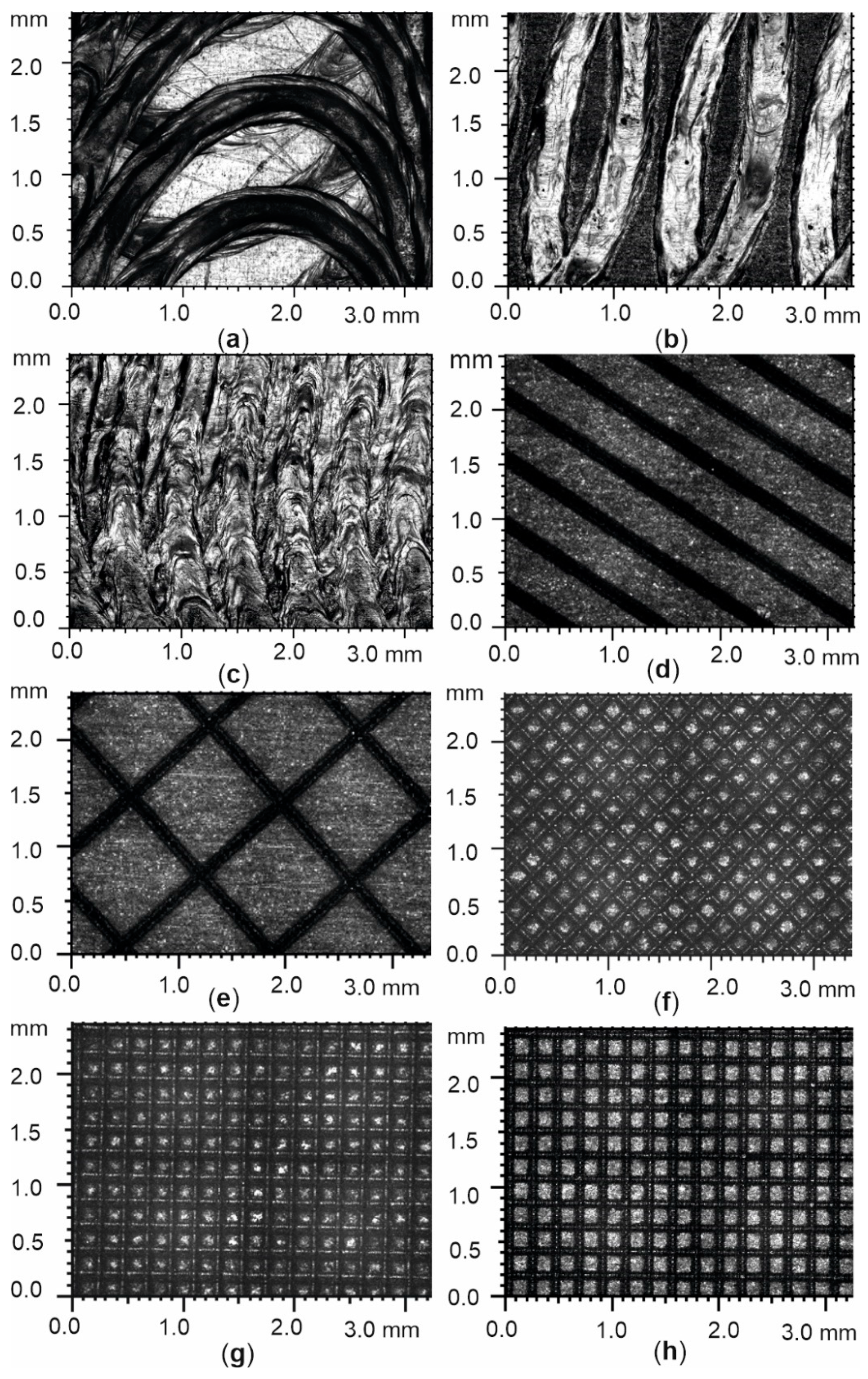
Figure 2.
3D topographies of laser-modified surfaces of the heated plate: a-c) vibration-assisted laser textures:: #VALS1 (a), #VALS2 (b) and #VALS3 (c); d-e) laser textures: #LS1 (d), #LS2 (e), #LS3 (f), #LS4 (g), #LS5 (h).
Figure 2.
3D topographies of laser-modified surfaces of the heated plate: a-c) vibration-assisted laser textures:: #VALS1 (a), #VALS2 (b) and #VALS3 (c); d-e) laser textures: #LS1 (d), #LS2 (e), #LS3 (f), #LS4 (g), #LS5 (h).
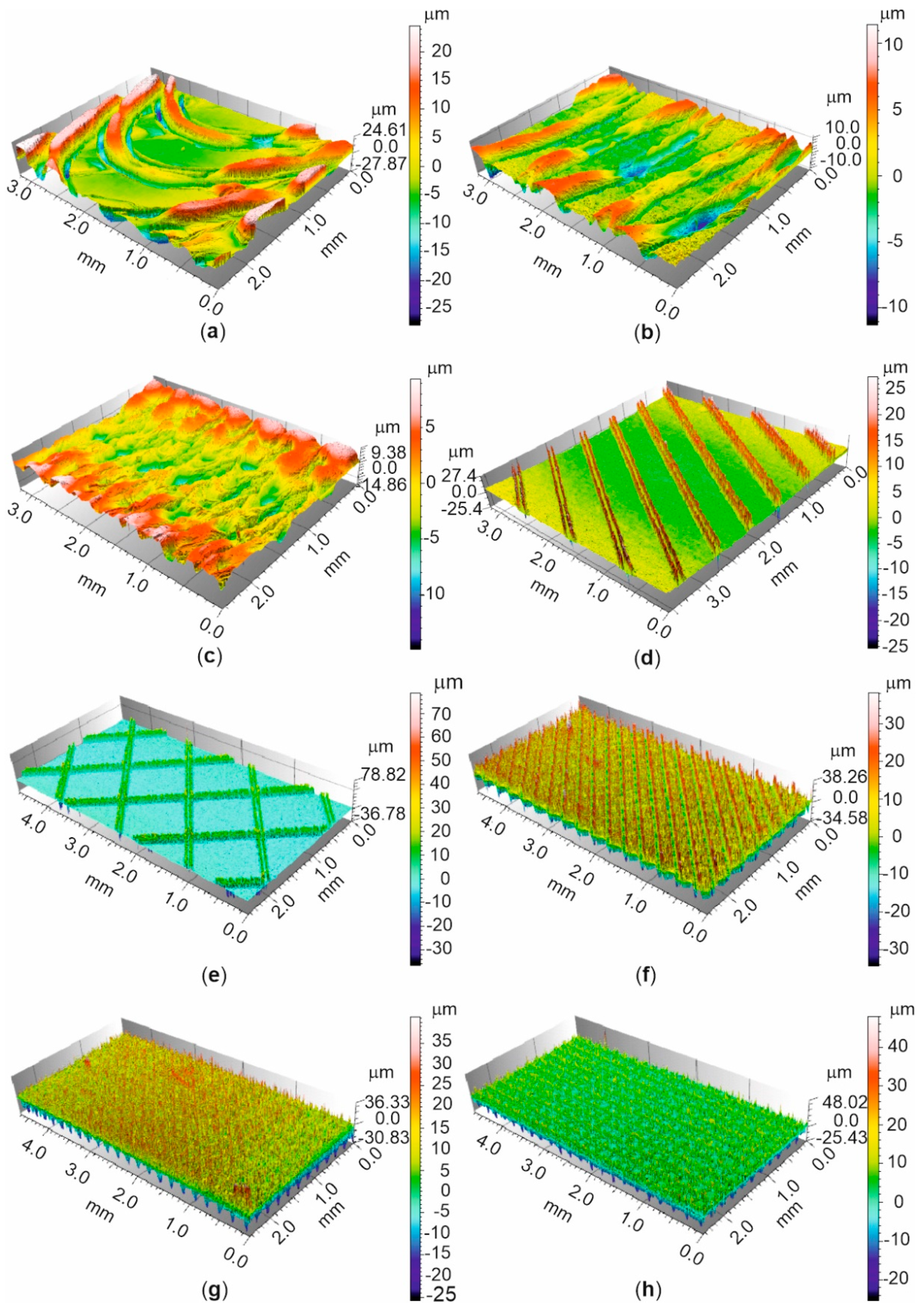
Figure 3.
Roughness profiles of the fragment of laser-modified surfaces of the heated plate: a-c) vibration-assisted laser textures: #VALS1 (a), #VALS2 (b), #VALS3 (c); d) laser texture #LS1.
Figure 3.
Roughness profiles of the fragment of laser-modified surfaces of the heated plate: a-c) vibration-assisted laser textures: #VALS1 (a), #VALS2 (b), #VALS3 (c); d) laser texture #LS1.
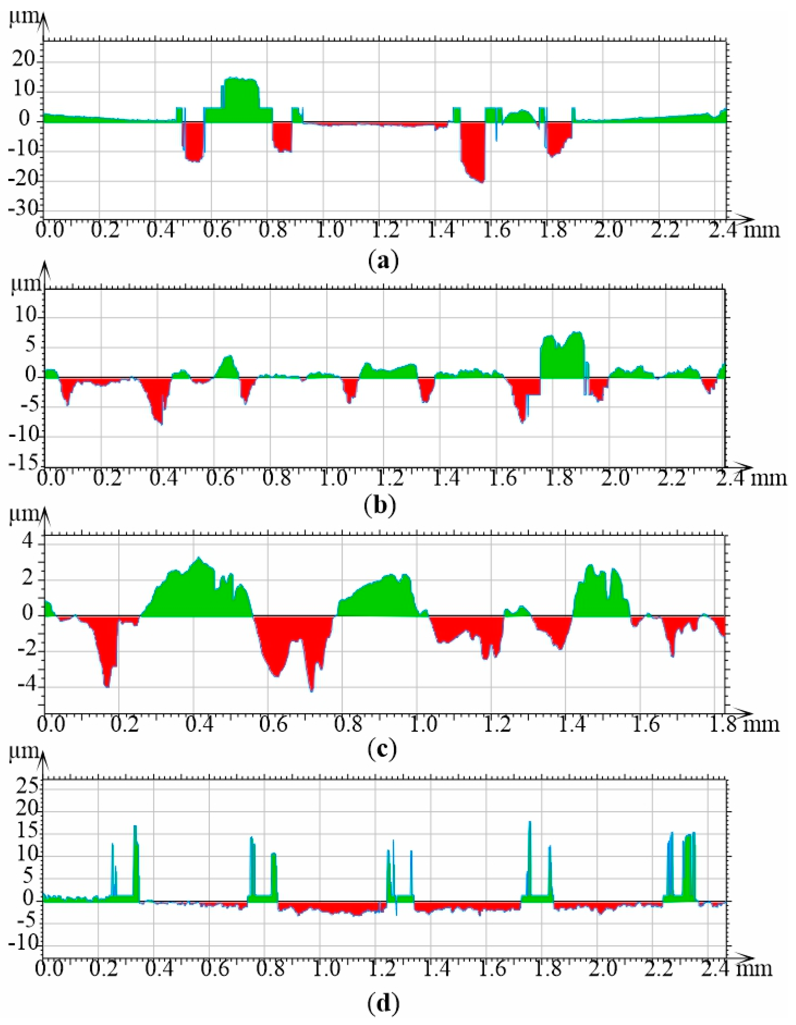
Figure 4.
Roughness profile of the fragment of laser-modified surfaces of the heated plate: #LS2 (a), #LS3 (b), #LS4 (c), #LS5 (d).
Figure 4.
Roughness profile of the fragment of laser-modified surfaces of the heated plate: #LS2 (a), #LS3 (b), #LS4 (c), #LS5 (d).
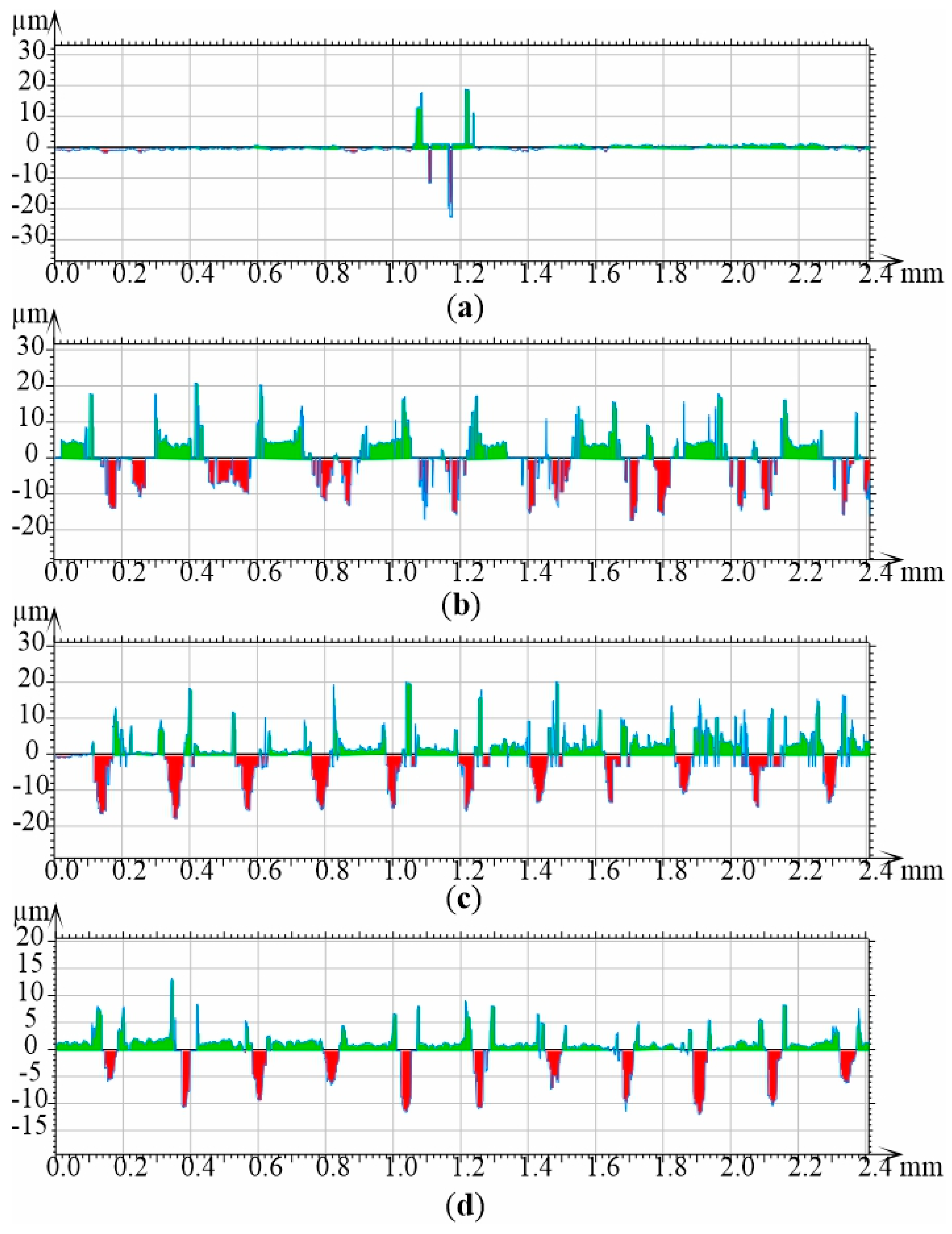
Figure 5.
Schematic diagrams of: a) the experimental setup with the test section: 1 – test section, 2 – gear pump, 3 – compensating tank, 4 – heat exchanger, 5 – filter, 6 – mass flow meter, 7 – dearator, 8, 10 – pressure meter, 9, 11– thermoelement, 12 – high-speed digital camera, 13 – LEDs, 14 – data acquisition station, 15 – PC computer, 16 – inverter welder, 17 – shunt, 18 – ammeter, 19 – voltmeter, 20 – IR camera; b) view of the test section components: 21 – a front cover, 22, 24 – a Teflon plate, 23 – a graphite plate with enhanced heated plate, 25 – a channel body with an O-ring, and glass plane.
Figure 5.
Schematic diagrams of: a) the experimental setup with the test section: 1 – test section, 2 – gear pump, 3 – compensating tank, 4 – heat exchanger, 5 – filter, 6 – mass flow meter, 7 – dearator, 8, 10 – pressure meter, 9, 11– thermoelement, 12 – high-speed digital camera, 13 – LEDs, 14 – data acquisition station, 15 – PC computer, 16 – inverter welder, 17 – shunt, 18 – ammeter, 19 – voltmeter, 20 – IR camera; b) view of the test section components: 21 – a front cover, 22, 24 – a Teflon plate, 23 – a graphite plate with enhanced heated plate, 25 – a channel body with an O-ring, and glass plane.
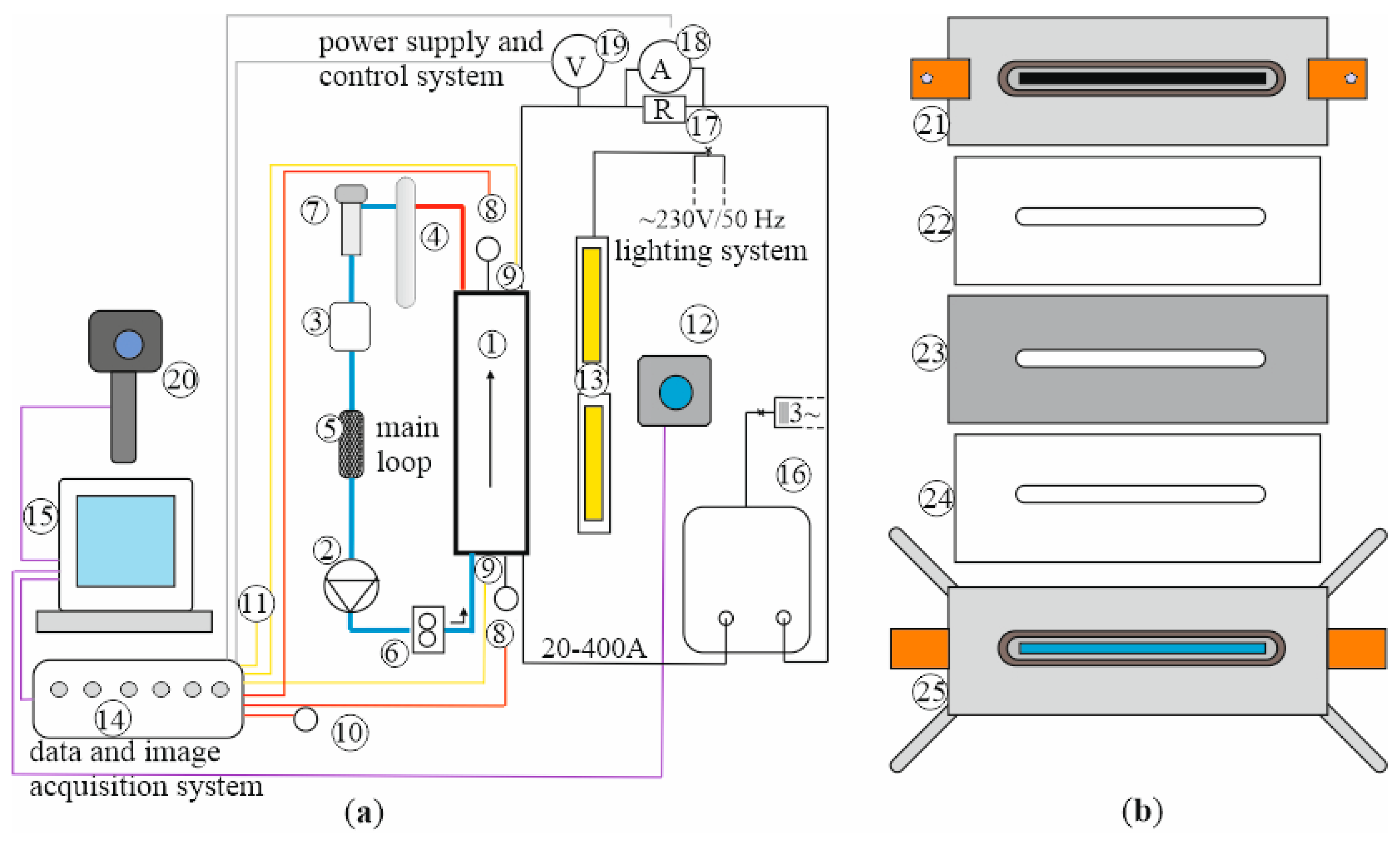
Figure 6.
Plate temperature measurements (due to infrared thermography) versus distance from the minichannel inlet, at three heat flux values transferred to the fluid in the minichannel: 37.6 kW/m2, (a), 48.5 kW/m2 (b) and 94.9 kW/m2 (c).
Figure 6.
Plate temperature measurements (due to infrared thermography) versus distance from the minichannel inlet, at three heat flux values transferred to the fluid in the minichannel: 37.6 kW/m2, (a), 48.5 kW/m2 (b) and 94.9 kW/m2 (c).
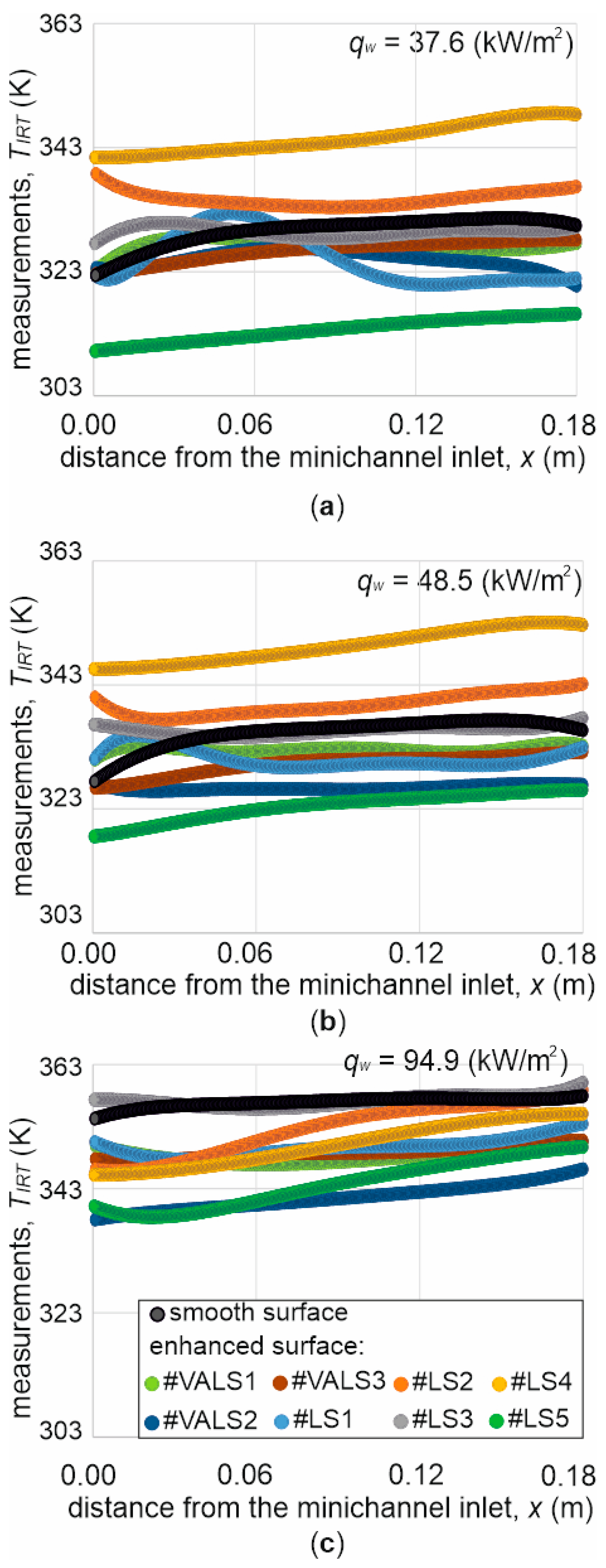
Figure 7.
Heat transfer coefficient versus distance from the minichannel inlet, the subcooled boiling region, at two-heat flux transferred to the fluid in the minichannel: 37.6 kW/m2 (a) and 48.5 kW/m2 (b).
Figure 7.
Heat transfer coefficient versus distance from the minichannel inlet, the subcooled boiling region, at two-heat flux transferred to the fluid in the minichannel: 37.6 kW/m2 (a) and 48.5 kW/m2 (b).
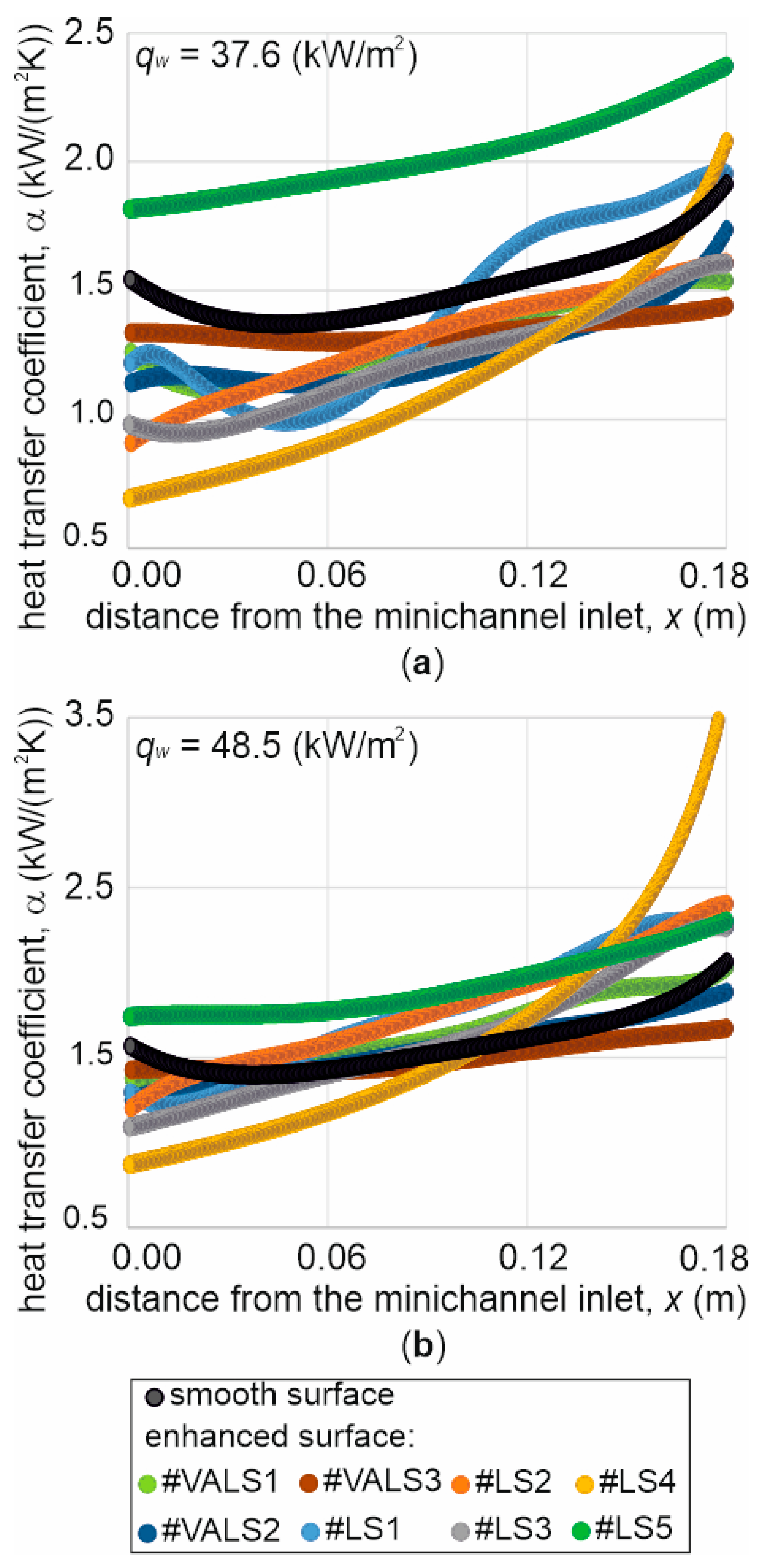
Figure 8.
Heat transfer coefficient versus distance from the minichannel inlet, the saturated boiling region, at two-heat flux transferred to the fluid in the minichannel: 48.5 kW/m2 (a) and 94.9 kW/m2 (b).
Figure 8.
Heat transfer coefficient versus distance from the minichannel inlet, the saturated boiling region, at two-heat flux transferred to the fluid in the minichannel: 48.5 kW/m2 (a) and 94.9 kW/m2 (b).
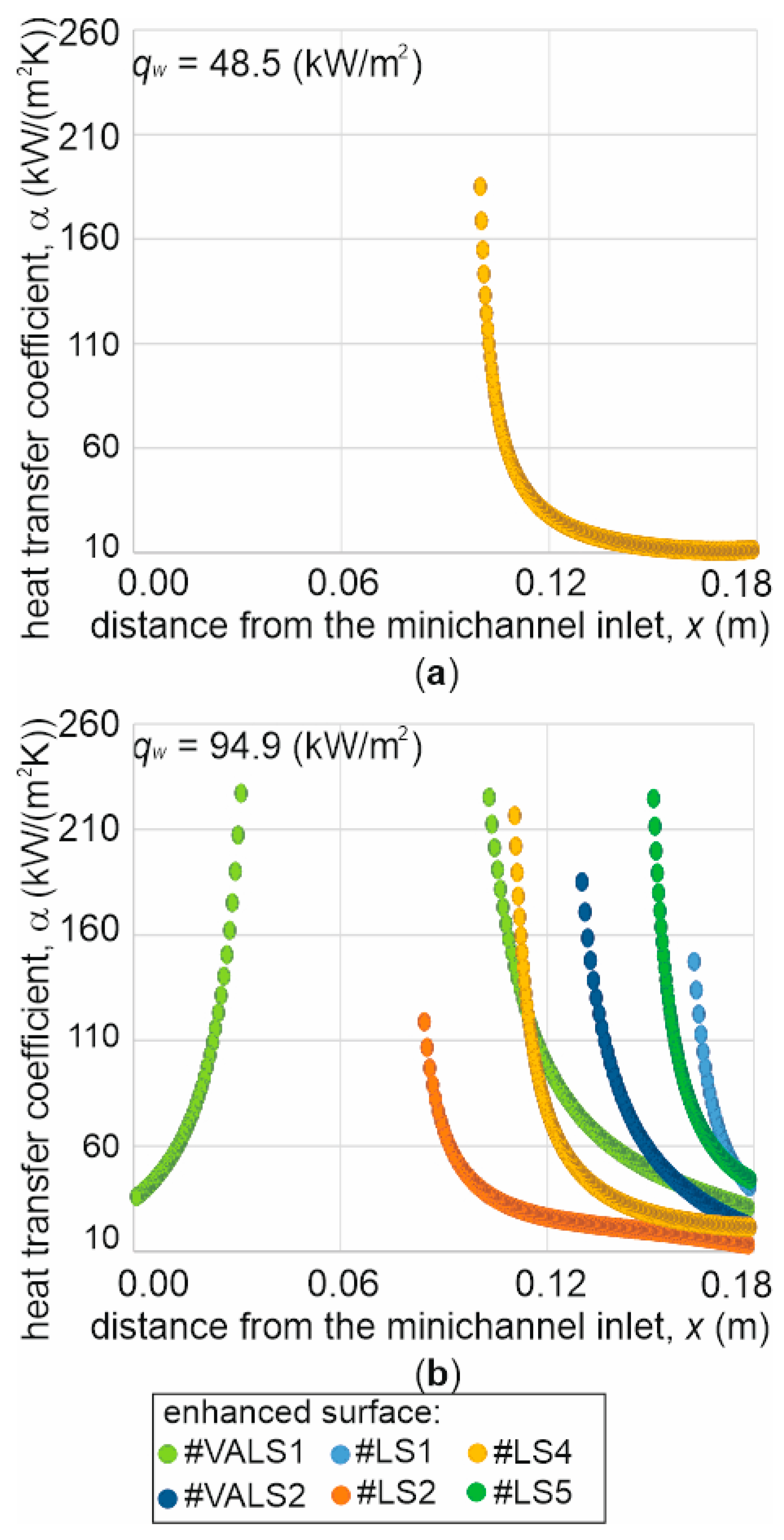
Figure 9.
Boiling curves generated for 0.12 m distance from the minichannel inlet; for laser-modified surfaces of the heated plate: vibration-assisted laser textures: #VALS1, #VALS2,#VALS3 (a) and la ser textures: #LS1, #LS2, #LS3, #LS4, #LS5 (b); ONB - onset of nucleate boiling.
Figure 9.
Boiling curves generated for 0.12 m distance from the minichannel inlet; for laser-modified surfaces of the heated plate: vibration-assisted laser textures: #VALS1, #VALS2,#VALS3 (a) and la ser textures: #LS1, #LS2, #LS3, #LS4, #LS5 (b); ONB - onset of nucleate boiling.
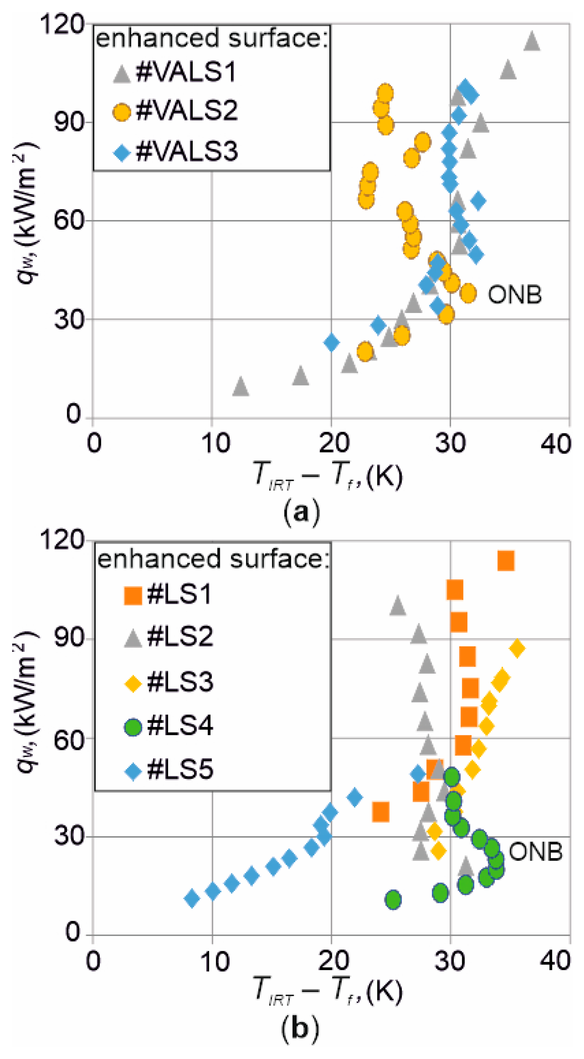
Figure 10.
Images of two-phase flow structures for three heat fluxes (the same as in Figure 6) and enhanced heated plate surfaces: three vibration-assisted laser textures: #VALS1 (a), #VALS2 (b), #VALS3 (c) and one selected laser texture #LS1 (d).
Figure 10.
Images of two-phase flow structures for three heat fluxes (the same as in Figure 6) and enhanced heated plate surfaces: three vibration-assisted laser textures: #VALS1 (a), #VALS2 (b), #VALS3 (c) and one selected laser texture #LS1 (d).
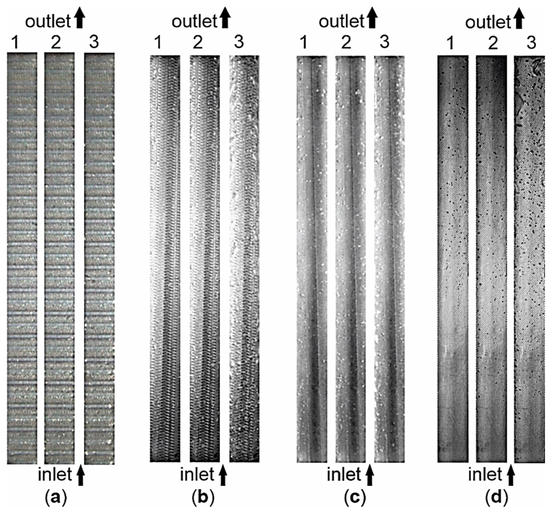
Figure 11.
Images of two-phase flow structures for three heat fluxes (the same as in Figure 6) and enhanced heated plate surfaces – four laser textures: #LS2 (a), #LS3 (b), #LS4 (c), #LS5 (d).
Figure 11.
Images of two-phase flow structures for three heat fluxes (the same as in Figure 6) and enhanced heated plate surfaces – four laser textures: #LS2 (a), #LS3 (b), #LS4 (c), #LS5 (d).
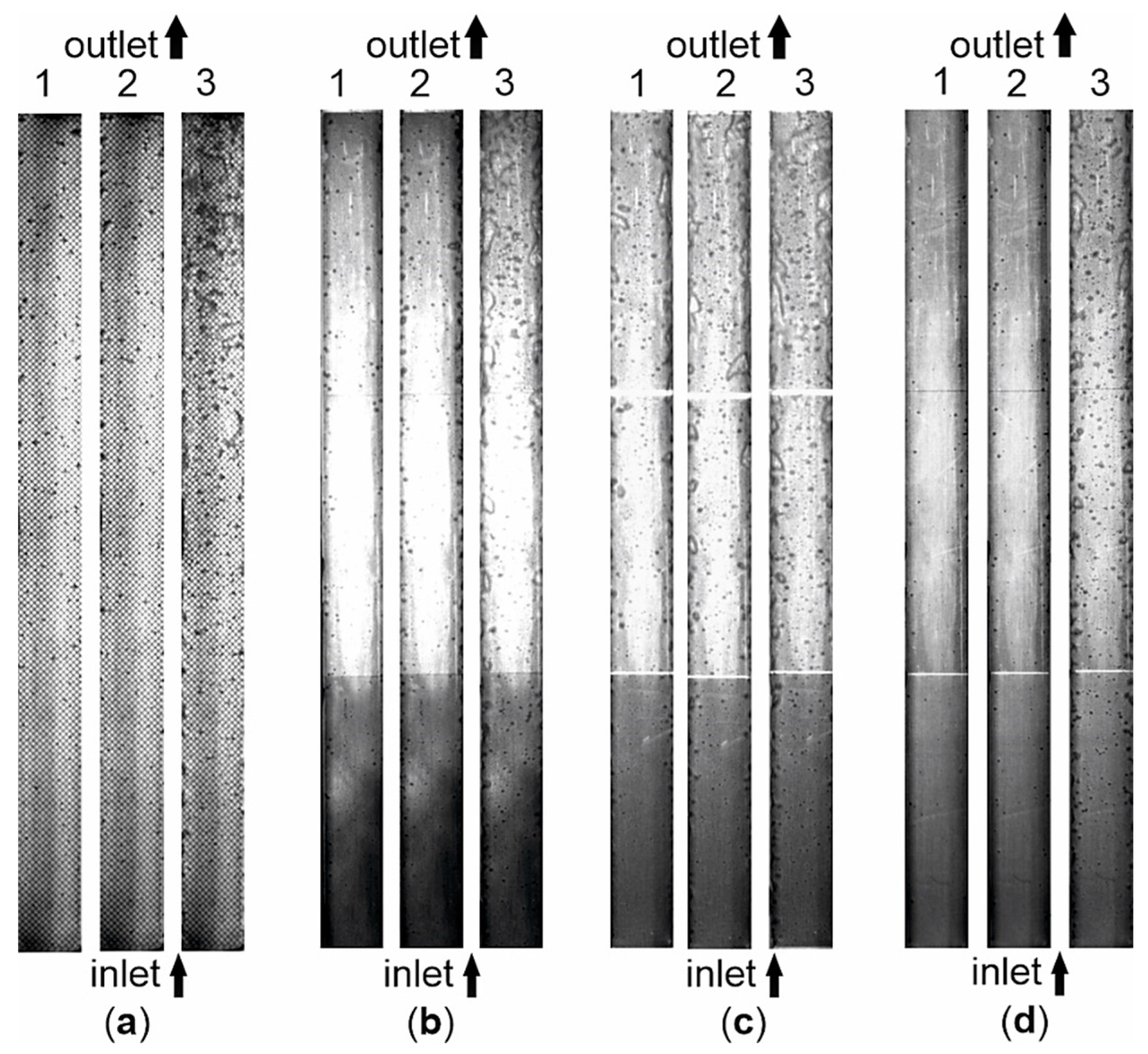

Table 1.
The processing parameters of the laser surface textures.
| Name of Laser Surface | The Basic Plate | Thickness of the Plate | Type of Laser | Laser Power | Other Properties |
|---|---|---|---|---|---|
| #VALS1 | Hastelloy X | 0.65 mm | CO2 Trumpf Lasercell 1005 | 2500 W | Scan velocity of 4 m/min Argon blow intensity of 10 l/min |
| #VALS2 | Haynes-230 | 0.45 mm | CO2 Trumpf Lasercell 1005 | 1500 W | Scan velocity of 5 m/min Argon blow intensity of 10 l/min |
| #VALS3 | Haynes-230 | 0.45 mm | CO2 Trumpf Lasercell 1005 | 1250 W | Scan velocity of 2.5 m/min Argon blow intensity of 10 l/min |
| #LS1 | Haynes-230 | 0.45 mm | Fiber Laser 30W, marking machine, laser engraver | 30 W | Scan velocity of 100 mm/s wavelength of 1064 nm frequency of 20 KHz |
| #LS2 | Haynes-230 | 0.45 mm | Fiber Laser 30W, marking machine, laser engraver | 30 W | Scan velocity of 100 mm/s wavelength of 1064nm frequency of 20 KHz |
| #LS3 | Haynes-230 | 0.45 mm | SPI 20 laser, single-mode, pulsed fiber lasers |
20 W | Scanning velocity of 1 m/s Maximum pulse energy 0.8 mJ Pulse duration 200 ns frequency of 25 KHz |
| #LS4 | Haynes-230 | 0.45 mm | SPI 20 laser, single-mode, pulsed fiber lasers |
20 W | Scan velocity of 0.5 m/s Maximum pulse energy 0.8 mJ Pulse duration 200 ns frequency of 25 KHz |
| #LS5 | Haynes-230 | 0.45 mm | SPI 20 laser, single-mode, pulsed fiber lasers |
20 W | Scanning velocity of 1 m/s Maximum pulse energy 0.8 mJ Pulse duration 200 ns frequency of 25 KHz |
Table 2.
Maximum dimensions (depth and height) of the laser-modified surfaces.
| Maximum Dimension [µm] | #VALS1 | #VALS2 | #VALS3 | #LS1 | #LS2 | #LS3 | #LS4 | #LS5 |
|---|---|---|---|---|---|---|---|---|
| Depth | 20.73 | 7.985 | 4.272 | 3.347 | 22.57 | 17.32 | 17.76 | 12.02 |
| Height | 14.77 | 7.595 | 3.293 | 17.74 | 18.70 | 20.66 | 20.02 | 13.11 |
Table 3.
Roughness parameters of the laser-modified textures tested.
| Rough-ness para-meter [unit] |
#VALS 1 |
#VALS 2 |
#VALS 3 |
#LS1 | #LS2 | #LS3 | #LS4 | #LS5 |
|---|---|---|---|---|---|---|---|---|
| Profile roughness parameters | ||||||||
| Rp [µm] | 9.958 | 4.989 | 2.517 | 16.17 | 17.71 | 18.99 | 19.57 | 8.611 |
| Rv [µm] | 16.01 | 7.436 | 3.658 | 2.303 | 12.31 | 17.33 | 15.55 | 11.34 |
| Rz[µm] | 25.96 | 12.37 | 6.175 | 18.47 | 30.02 | 36.33 | 35.11 | 19.95 |
| Rc [µm] | 16.41 | 7.589 | 4.523 | 12.52 | 25.02 | 26.06 | 18.43 | 12.93 |
| Rt [µm] | 28.52 | 14.29 | 6.175 | 20.58 | 41.29 | 37.82 | 35.94 | 20.41 |
| Ra [µm] | 4.834 | 2.040 | 1.445 | 1.578 | 0.9218 | 5.152 | 4.447 | 2.329 |
| Rq [µm] | 6.820 | 2.714 | 1.637 | 2.806 | 2.902 | 7.005 | 6.276 | 3.576 |
| Rsk [-] | -0,8038 | -0.6421 | -0.1547 | 3.711 | 2.511 | -0.1004 | -0.1309 | -1.464 |
| Rku [-] | 3.177 | 3.508 | 1.859 | 17.77 | 41.63 | 3.437 | 4.509 | 5.720 |
| Material ratio of the profile andprofile section height difference | ||||||||
| Rmr [%] | 6.054 | 5.524 | 22.56 | 0.3300 | 0.7206 | 0.8006 | 1.601 | 0.7968 |
| Rdc [µm] | 8.391 | 4.222 | 3.012 | 1.240 | 1.026 | 10.98 | 6.861 | 1.732 |
| Area roughness parameters | ||||||||
| Sq [µm] | 9.234 | 3.503 | 3.134 | 3.903 | 5.187 | 8.523 | 7.314 | 5.401 |
| Ssk [-] | 0.3201 | 0.1661 | 0.0934 | 2.358 | 0.7284 | -0.5675 | -0.5935 | -0.66 |
| Sku [-] | 3.338 | 3.574 | 2.677 | 13.25 | 13.50 | 5.478 | 4.300 | 5.046 |
| Sp [µm] | 24.61 | 16.11 | 9.381 | 27.43 | 78.82 | 38.26 | 36.33 | 48.02 |
| Sv [µm] | 27.87 | 15.84 | 14.86 | 25.42 | 36.78 | 34.58 | 30.83 | 25.43 |
| Sz [µm] | 52.48 | 31.95 | 24.24 | 52.85 | 115.6 | 72.85 | 67.16 | 73.44 |
| Sa [µm] | 6.658 | 2.769 | 2.511 | 2.326 | 2.693 | 5.496 | 5.022 | 3.654 |
where Rp – maximum height of the profile, Rv – maximum height of the profile, Rz – ten point height (deleted as an ISO parameter), Rc – mean height of the profile, Rt – total height of the profile, Ra – arithmetical mean deviation of the assessed profile, Rq – root mean square deviation of the assessed profile, Rsk – skewness of the assessed profile, Rku – kurtosis of the assessed profile, Rmr – material ratio of the profile, Rdc – profile section height difference, Sq – root mean square height, Ssk – skewness, Sku – kurtosis, Sp – maximum peak height, Sv – maximum pit height, Sz – maximum height, Sa – arithmetical mean height.
Table 4.
Elements/devices of the experimental setup.
| Element/Device (numbering, Figure 5a) |
General Informations |
|---|---|
| Main Flow Loop | |
| Minichannel (1) | Single minichannel with dimensions: 180 mm in length, 1.7 mm in depth, set at the vertical position 90° with fluid upward flow |
| Gear circulating pump (2) | Model: SK 63 S/2 TF with Nordac SK 500E frequency inverter, manufactured by Nord |
| Compensating tank (3) | Maintain the fluid pressure |
| Heat exchanger (4) | Type: pipe-in-pipe |
| Filter (5) | Solid–liquid separation |
| Coriolis mass flowmeter (6) | Model: Proline Promass A 100, manufactured by Endress+Hauser |
| Deaerator (7) | Enables bleeding the systems |
| Pressure meters (8) | Model: PMP71 Cerabar S (overpressure at the inlet/outlet), manufactured by Endress+Hauser |
| Thermocouples (9, 11) | K-type, 221 b, (9 at the inlet and outlet channel, 11 at ambient temperature), manufactured by Czaki Thermo-Product |
| Pressure meter (10) | Model: A-10 (atmospheric pressure), manufactured by Wika |
| Power Supply and Control System | |
| Heat source (16) | Current regulation in the range 20 A - 400 A |
| Shunt (17) | Model: 8B40-03, manufactured by Dataforth |
| Ammeter (18) | Model: 8B32-01, manufactured by Dataforth |
| Voltmeter (19) | Model: 8B41-12, manufactured by Dataforth |
| Data and Image Acquisition System | |
| High-speed digital camera (12), | Model: SP-5000M-CXP2, the CoaXpress interface with two channels, manufactured by JAI |
| Two data acquisition stations (14) | Model: DaqLab/2005 manufactured by IO-tech and model: MCC SC-1608G Series, manufactured by Measurement Computing |
| Infrared (IR) camera (20) | Model: E60, manufactured by FLIR |
| Lighting System | |
| Leds (13) | 8 high-power LED COB modules each with a power of 50 W |
Table 5.
Experimental thermal and flow parameters.
| Experimental Paramaters, (unit) |
Range of Values/Values |
|---|---|
| Inlet Pressure, pin (kPa) | 125.9 – 175.1 |
| Inlet Liquid Subcooling, ∆Tsub (°C) | 49.9 |
| Mass Flux, G (kg/(m2·s)) | 233.6 |
| Heat Flux, qw (kW/m2) | 37.6 – 94.9 |
Table 6.
Absolute errors of the heat flux and relative errors of the heat transfer coefficient at subcooled boiling region, for all laser textures tested.
Table 6.
Absolute errors of the heat flux and relative errors of the heat transfer coefficient at subcooled boiling region, for all laser textures tested.
| Surface Textured | Heat Flux (kW/m2) |
qw (%) | σ (%) |
|---|---|---|---|
| Subcooled boiling region | |||
| #VAL1 | 37.6 | 0.96 | 3.24 |
| #VAL2 | 0.82 | 3.02 | |
| #VAL3 | 0.78 | 2.97 | |
| #LS1 | 0.78 | 3.49 | |
| #LS2 | 0.84 | 3.15 | |
| #LS3 | 0.84 | 2.99 | |
| #LS4 | 1.29 | 3.13 | |
| #LS5 | 1.27 | 4.69 | |
Disclaimer/Publisher’s Note: The statements, opinions and data contained in all publications are solely those of the individual author(s) and contributor(s) and not of MDPI and/or the editor(s). MDPI and/or the editor(s) disclaim responsibility for any injury to people or property resulting from any ideas, methods, instructions or products referred to in the content. |
© 2024 by the authors. Licensee MDPI, Basel, Switzerland. This article is an open access article distributed under the terms and conditions of the Creative Commons Attribution (CC BY) license (http://creativecommons.org/licenses/by/4.0/).
Copyright: This open access article is published under a Creative Commons CC BY 4.0 license, which permit the free download, distribution, and reuse, provided that the author and preprint are cited in any reuse.


