

Submitted:
19 November 2024
Posted:
20 November 2024
You are already at the latest version
Abstract
The article presents the calculation of the main parameters of the double-sided oblique traction transmission of the VL-80c electric locomotive based on a comprehensive analysis of diagnostic parameters obtained by applying the Poisson normal distribution method for detected failures according to the data of the Uzbekistan depot.
Keywords:
Locomotive
; vibrations
; stressed-deformed state
; fatigue safety factors
; life calculation
; vibration protection
; algorithm
; program
; MATHCAD 15
1. Introduction
In modern foreign patent and sci-tech literature the problems of increasing reliability and durability of locomotive gear wheels of complex configuration in the process of their design, operation and modernisation are widely investigated [1,2,3,4,5,6,7,8]. It is obvious that the overall stress state of the wheel-motor block (WMB) elements of locomotives, as well as their supporting equivalent frames, will depend significantly on longitudinal, transverse and torsional dynamic components of traction forces arising in frames of complex configuration, as well as contact stresses arising from sharp temperature differences. These factors cause a 1.2 - 1.5 times decrease in the total service life of the locomotive wheel-engine unit elements.
Research has been conducted and is being conducted on this topic by leading scientists worldwide such as S.A. Brebbia (Wessex Institute of Technology, UK), G.M. Carlomagno (University of Naples di Napoli, Italy), A. Varvani-Farahani (Ryerson University, Canada), S.K. Chakrabarti (USA), S. Hernandez (University of La Coruna, Spain), S.-H. Nishida (Saga University, Japan). Authoritative scientific schools and prominent scientists in the CIS countries from MIIT, PGUPS, MAI, VNIIZhT, JSC VNIKTI, JSC Russian Railways, etc. worked on these issues. A significant contribution to solving many complex problems and checking theoretical conclusions related to the study of the processes of oscillations of the elastic self-aligning gear of the locomotive of the rolling stock was made by the Russian Research Institute of Railway Transport (CNII MPS) and the Russian Research Institute of Railcar Building (NIIV), where along with theoretical studies, a large number of experimental studies (bench and full-scale ones) were conducted [1,2,3,4,5,6,7,8]. In Uzbekistan, the academician of the Academy of Sciences of the Republic of Uzbekistan, professor, doctor of technical sciences Glushchenko A.D., professors Fayzibaev Sh.S., Khromova G.A., Mukhamedova Z.G. and their students dealt with the problems of optimizing the systems of elastic self-aligning gear of rolling stock [8,9,10,11,12,13,14].
We have conducted surveys of traction transmission of VL-80s electric locomotives on emerging breakdowns and failures from 2017 to 2023 according to Uzbekistan depot data. The gearing of VL80-c electric locomotives is rigid, double-sided, helical and consists of two gears and two pinions enclosed in pairs in a protective casing. Figure 1 shows the wheel-motor block (WMB) of a VL-80s electric locomotive with a double-sided helical gear with an all-roller gear.
The advantages of helical gearing are that:
- -
- helical teeth, located at an angle of 24°37'12", ensure simultaneous gearing of pinion and gear teeth on both sides (due to axial displacement of the TEE armature with two pinions in roller bearings by 6÷8 mm);
- -
- high smoothness of gearing, because the wheel teeth do not enter and exit the gear at once with their entire width b, but gradually;
- -
- reduction of noise and additional internal dynamic load.
The disadvantage of helical gears is the axial force tending to move the wheel with the shaft and the required axial fixation of the shaft. Therefore, the tine angle is limited and is recommended to be taken as According to the data of the works, the reject dimensions of the gear are as follows [4,5,6,7]:
- -
- tooth thickness wear is allowed not more than 3.5 mm, measured at a height of 10 mm from the top of the tooth;
- -
- lateral (axial) clearance between the teeth of the gear and the gear wheel in gearing is allowed not more than 5.5 mm;
- -
- The radial clearance between the gear and gear teeth should be 2.5+5.3 mm and depends on the wear of the babbitt in the motor axle bearing shells ("MABs");
- -
- The pinion may not hang down more than 6 mm from the gear wheel;
- -
- Cracks in the teeth are not permitted;
- -
- Dents, gouges, splinters on the teeth are allowed: on the gear - not more than 15 % (depth not more than 3 mm), on the gear wheel - not more than 25 % of the tooth surface (the number of such teeth is not limited).
It has been established that the most dangerous type of failure leading to failure of traction gear and damage to other parts is tooth breakage, which can be caused by large overloads of impact and static action or fatigue of the material from repeatedly flowing loads. Possible causes may be: concentration of dynamic loads along the length of the teeth due to manufacturing errors or large elastic deformations of the shafts; wear of the teeth resulting in weakening and increase of dynamic loads; insertion of moving gears into the gearing on the move. Cracks usually appear at the base of the teeth on the side of the stretched fibres.
In fatigue damage the fracture is concave on the gear body, in overload damage it is convex. The teeth of wide helical gears usually break out along the oblique section (from the base to the top of the opposite face), so the teeth must be calculated for bending and contact stiffness to prevent breakage.
Let us consider two types of tooth damage subject to analytical calculation for their prevention - fatigue pitting of the tooth surface and tooth breakage. Fatigue pitting from contact stresses and friction forces is the main type of tooth surface damage. Fatigue pitting of the tooth surface (i.e. falling out of pieces of metal from the surface of the wheel tooth) is preceded by the nucleation of cracks on its surface, which is possible if the contact stress in the areas of cracks σ_H> σ_H0, (contact endurance limit of the tooth material). Therefore, the main criterion for the operability of the teeth of such wheels is fatigue contact strength. Tooth failure is most commonly of a fatigue nature from the prolonged action of alternating bending stresses σ_F in the tooth stems.
Fatigue cracking is also favoured by stress concentrations, and the resulting crack develops, leading to sudden tooth failure. Teeth with high surface hardness (at HB > 350 ) are particularly prone to breakage. Therefore, the main criterion for the operability of such wheels is the bending fatigue strength of the teeth.
2. Materials and Methods
Object of research are dynamic calculations of bending and contact stiffness of teeth of pinion gear and wheel of double-sided helical traction gear of electric locomotive VL-80s, and also development of new methodology of calculation of strength of teeth on bending and torsion stresses taking into account diagnostic parameters according to operation data.
The paper uses Gaussian system and matrix analysis methods and applies numerical methods: Fourier method, piecewise linear approximation method, iteration method and boundary element method (the Boundary Element Technology). The numerical studies were carried out in C# language and MATHCAD 15 programming environment, for software products have been received a certificate of official registration of the computer program of the Republic of Uzbekistan No. DGU 02322,07664,10286 [9,10,11].
3. Results
At dynamic calculation of bending and contact stiffness of teeth of pinion gear and wheel of double-sided helical traction gear of electric locomotive VL-80s the first stage is calculation of contact shear stresses of helical gear taking into account diagnostic parameters according to operation data.
The gear is forged from chromium-nickel alloy steel 20XNZA with subsequent carburising and hardening of tooth surfaces along the entire contour. Inside has a tapered hole with a slope of 1:10 for pressing onto the shaft of the TEE armature. There is a 15 mm wide notch on the side of the hole for the nut. The gear is cut 21 helical teeth at an angle of 24°. The gear wheel is forged from 55X carbon steel and consists of a hub, a middle part in the form of a disc with holes and a crown with teeth. The forged gear is ground on all sides, 16 relief holes are drilled in the centre section and 88 oblique teeth are cut on the crown at an angle of 24°. The teeth are cemented and hardened.
I. Let us calculate the contact fatigue resistance of the active surfaces of wheel teeth.
The purpose of calculation is to establish the dependence of serviceability index (contact stress σ_H) on the external load and geometric dimensions of helical gear wheels. The calculation scheme for the calculation of the wheel tooth surface for contact strength is shown in Figure 3.
Based on the Hertz formula [2,3] for the case of compression along the formations of two cylinders, we take the calculation formula as
where - specific normal stress (intensity of interaction between cylinders of length , compressed by force );
- - reduced radius of curvature of cylinders;
- - the reduced modulus of longitudinal elasticity of the gear and gear cylinder material;
- и - longitudinal elastic modulus of the material of the first and second cylinder, respectively;
- - Poisson's coefficient.
It has been experimentally established that the lowest contact strength has the near-pole zone of the working surfaces of the teeth, in which the highest loads act on the teeth (the full load is transmitted by one pair of teeth) and the sliding speed of the teeth V_ck is not equal to zero [7].
The teeth are regarded as two cylinders of length b (gear ring width) with a radius equal to the radius of curvature of the involutes of the gear and wheel tooth profiles at the meshing pole, i.e. , . From the triangles О1 N1 P and О2 N2 P (see Figure 2) the radiuses of curvature can be written down and through them the reduced radius of curvature
here the sign "plus" is for external, "minus" for internal gearing.
pred= 2 d1d2sinα24 d2±d1sinα= d2 sinα2 u ±1= d1 usinα2 u ±1
Calculate the specific load on the contacting teeth
where – total length of contact lines at the boundary of one- and two-pair gearing.
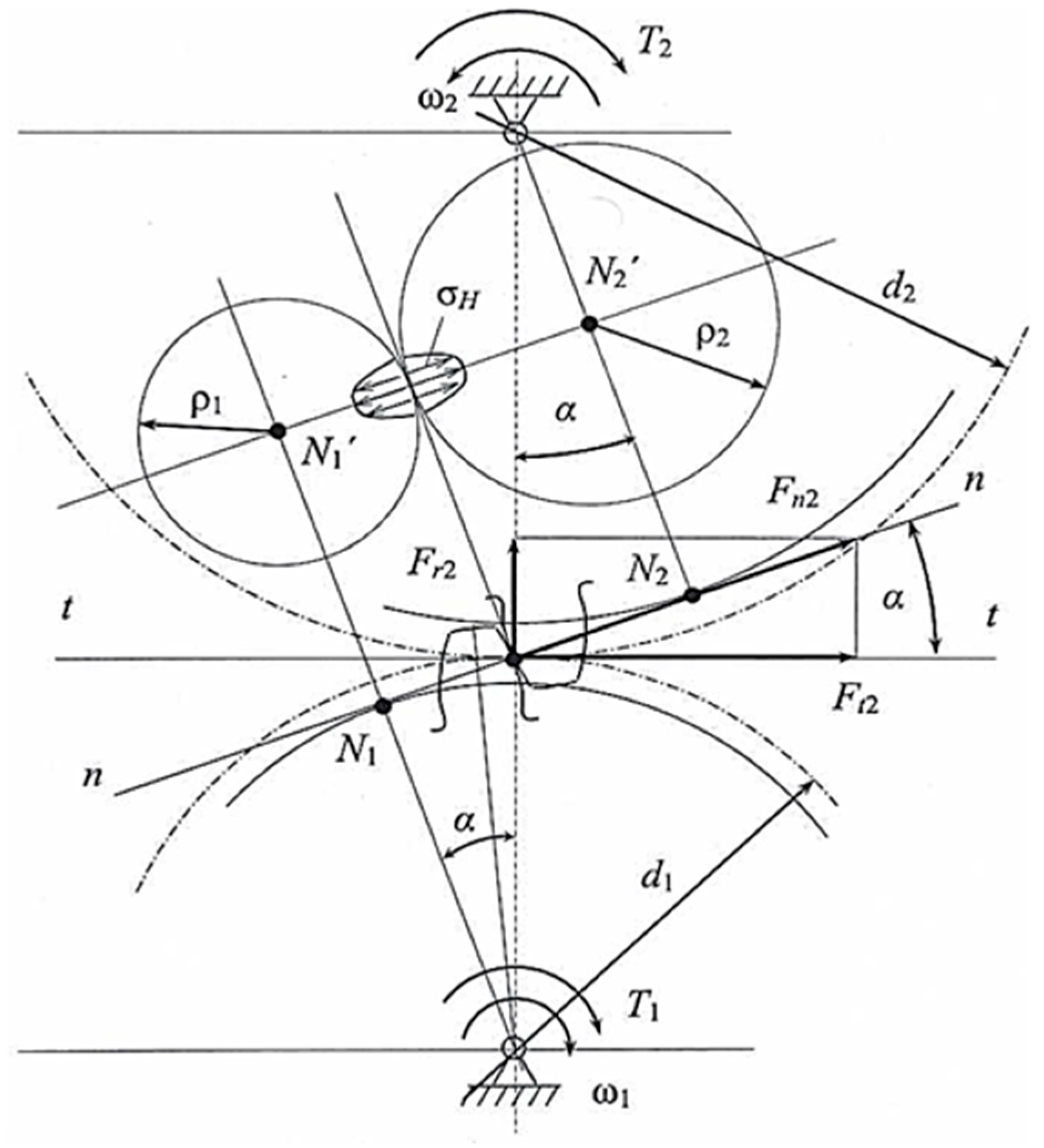
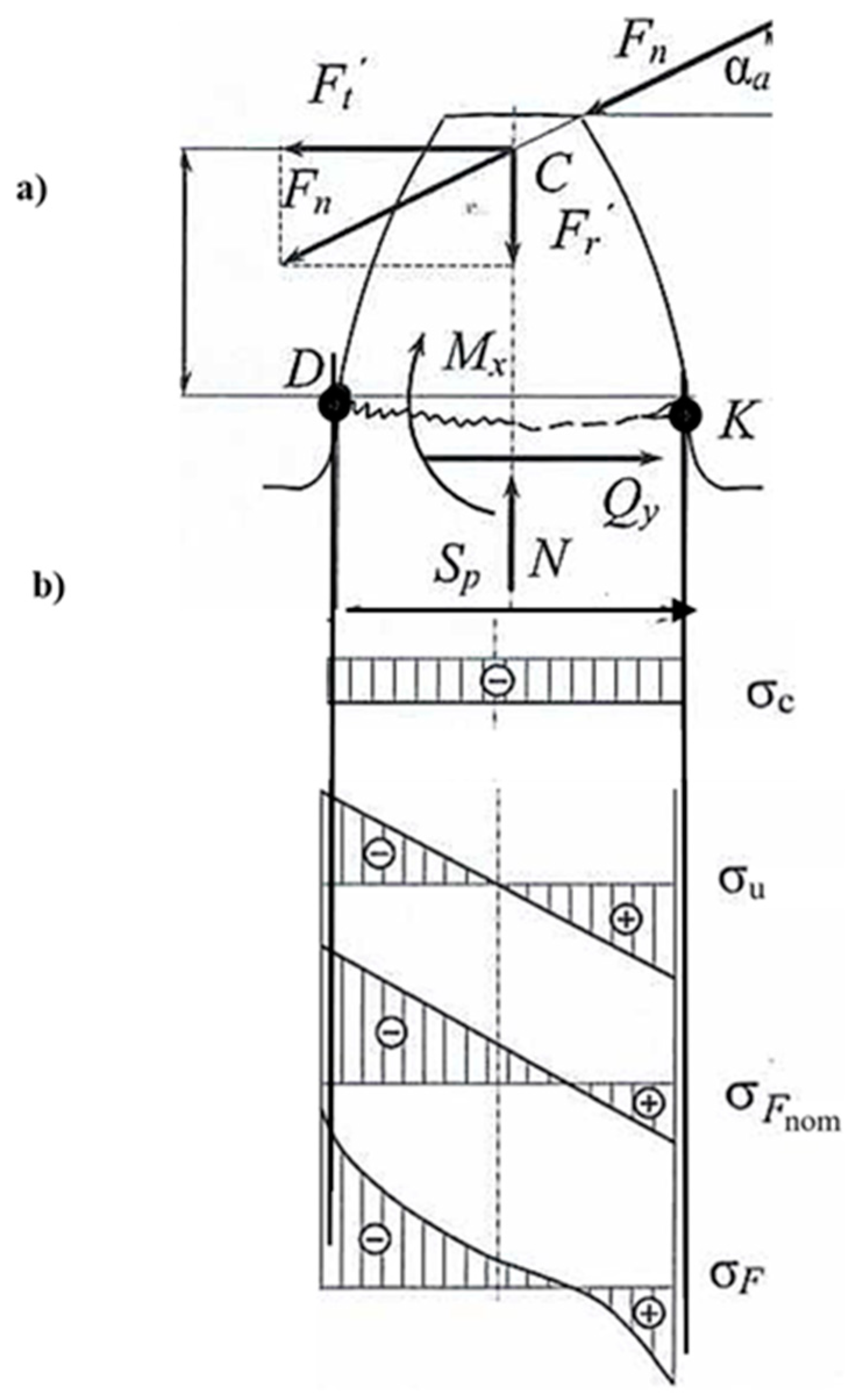
Figure 2.
Calculation scheme for calculation of wheel teeth surface on contact strength of the gear wheel in the wheel-motor block (WMB) of electric locomotive VL-80s.
Figure 2.
Calculation scheme for calculation of wheel teeth surface on contact strength of the gear wheel in the wheel-motor block (WMB) of electric locomotive VL-80s.
Figure 3.
Calculation scheme for calculation of wheel teeth for bending fatigue resistance (a) for a gear wheel in the wheel-motor block (WMB) of electric locomotive VL-80s and stress diagrams in the tooth stem of the wheel (b).
Figure 3.
Calculation scheme for calculation of wheel teeth for bending fatigue resistance (a) for a gear wheel in the wheel-motor block (WMB) of electric locomotive VL-80s and stress diagrams in the tooth stem of the wheel (b).
By substituting the values and into the Hertz formula (1) and replacing , we get
Denoting:
- coefficient, taking into account the shape of contacting tooth surfaces (for normal wheels at , 1,76); - coefficient, taking into account mechanical properties of materials of contacting wheels (for steel wheels 275 МPa1/2 ); - coefficient taking into account the total length of the contact lines (for spur gearing ).
Then, we obtain the calculation dependence in the form recommended by GOST for verification calculation
where - coefficient of non-uniformity of load along the length of the contact lines of gearing (along the tooth length for spur wheels), due to misalignment of wheel teeth caused by shaft deflection, deformations of the housing, bearings, assembly error;
- dynamic load factor, which takes into account the occurrence of additional dynamic loads in the gearing, i.e. takes into account the internal dynamics of the transmission caused by inaccuracies in the manufacturing of wheel teeth in terms of circumferential pitch (usually ).
The specified coefficients are selected according to pre-designed tables based on diagnostic parameters from operation data.
It should be noted that the verification calculation is carried out on the wheel, because the wheel material is assumed to be of lower strength than the gear due to the fact that the tooth of the wheel is less likely to gear (by a factor of one) than the tooth of the gear. Therefore, formula (4) can be modified. For this purpose we input the following substitutions
Then
In formula (6), the torque is given in N∙m, а = – in mm, contact stresses in MPa. The numerical coefficient 103 is used to harmonise the dimensions of these quantities.
In the planning calculation, or must be determined from the given torque and transmission ratio u.
To obtain the calculated formula for the centre-to-centre distance, we introduce in expression (6) , where - wheel width coefficient with respect to centre distance. Then expressing a from this formula we obtain
Denote by – auxiliary factor; for spur gears it is recommended to = 49,5 MPa1/3 (at = 1).
Final formula for the design calculation of the centre-to-centre spacing of closed helical spur steel gears
If it is necessary to determine d1 at the initial stage of design calculation, we introduce the gear ring width coefficient into formula (4) , and expression
whereupon we obtain
From where the gear dividing diameter
where - auxiliary coefficient; for steel spur wheels is recommended to = 78 MPa1/2 . In formulas (7) and (8) T2 is given in N∙m, contact stresses in MPa, and - in mm. Values of selected according to the recommendations in Table 1. By choosing , determine by formula .
From formulas (5), (6), (8) it follows that the value of contact stresses does not depend separately on the modulus or on the number of teeth, but is determined only by their product or wheel diameters. According to the conditions of contact strength for given or a, the transmission modulus can be as small as desired, or correspond to the equality and .
The value of m is selected based on practical recommendations and diagnostic parameters, and then the tooth is tested for bending fatigue. When checked, it is possible to obtain much smaller than [] because the load capacity at tooth surface hardness H < 350НВ is limited by contact fatigue rather than bending fatigue.
If the calculated value exceeds the permissible value , then at the accepted values of d and m increase m. This means that bending fatigue, rather than contact fatigue, is decisive in a given transmission of the selected materials. In practice, such cases occur in the case of wheels with high-hardness teeth at the H > 50HRC.
The following should be considered when selecting a module.
Fine-modular wheels with a large number of teeth are better for smooth running conditions (increases) and for economic reasons.
However, for power transmissions, it is recommended to take 2 мм. In high-speed gears, it is recommended to use the following for noise reduction 26.
Large-modular wheels can operate for a long time after the onset of pitting and are less sensitive to overloading.
Given these diagnostic parameters, the following recommendations should be used in the orientated evaluation of the module.
1. By choosing from Table 2, determine = , where ; is obtained from the contact fatigue calculation. If a is obtained from the calculation, then we determine , then , and further .
2. The modulus is chosen according to empirical dependencies:
The obtained modulus value is rounded to the values of GOST 9563.
Row 1: 1; 1,25; 1,5; 2; 2,5; 3; 4; 5; 6; 8; 10; 12; 16; 20... .
Row 2: 1,125; 1,375; 1,75; 2,25; 2,75; 3,5; 4,5; 5,5; 7; 9; 11; 14; 18; 22... . When assigning modules to row 1, you should give preference to row 2.
When selecting , it is recommended to use a number of::
0,1; 0,125; 0,16; 0,2; 0,25; 0,315; 0,4; 0,5; 0,63; 0,8; 1; 1,25.
II. Next, we calculate the bending fatigue resistance of the wheel teeth.
This calculation is the basic calculation for gears with high hardness of the tooth surface (at H 350НВ). The purpose of the calculation is to establish the dependence of the operability index (stress in the tooth foot section) on external loading and geometric dimensions of the teeth.
Initial bases for the calculation:
- 1)
- the calculation is made for the moment of force application at the tooth apex (Figure 4). This corresponds to the start of gearing for a wheel tooth and the end of gearing for a gear tooth. Although there is theoretically another pair of teeth in gear at this point, it is assumed that the entire load is transferred by one pair of teeth. Only for precisely manufactured gears (above 6th degree of accuracy) it can be considered that the load is transmitted by two pairs of teeth
Let us transfer the force along its line of action on the symmetry axis of the tooth to point C and decompose it into two force components: circumferential and radial ;
Then
Here is the pressure angle at the tooth apex, which is greater than the pressure (gearing) angle a on the dividing circle.
3) having plotted the normal stresses (Figure 4), we obtain that the highest stresses occur in the indicated dangerous section. The concentration of stresses is also observed here.
The calculated stress is the stress on the tensile side of the tooth, i.e.
fatigue fracture cracks occur on the tensile side of the tooth. This is not random, because the surface layers of the tooth material, as experiments show, offer less resistance to alternating tensile stresses than to compressive stresses.
4) For the dangerous section D - K, located near the chord of the basic circle, we write (taking into account the stress concentration)
where – calculated nominal stress;
– theoretical stress concentration coefficient.
where - axial moment of resistance of the dangerous section of the tooth stem;
- tooth stem cross-sectional area;
, - design tooth height and thickness, respectively;
b - Tooth length (width of the gear wheel ring).
Values and can be expressed in fractions of the tooth modulus: ;
where , - coefficients according to design height and design tooth thickness.
Figure 3 shows that the force causes transverse bending of the tooth and the force causes compression of the tooth. Thus, in the dangerous cross-section of the tooth (in the stem at the transition point of the involute to the tooth flange) there are three internal force factors: bending moment Mx, transverse force Qy and longitudinal force Nz.
Substituting in expression (12) the values included in it, we obtain
Denote by – tooth shape coefficient, and introducing design load coefficients and , we obtain a formula for the verification calculation of straight wheel teeth for bending fatigue resistance
Substituting in the form (14) , we get
To obtain the formula for the design calculation it is necessary to substitute in expression (15) and solving it with respect to the tooth modulus
Denoting by = 1,4 – auxiliary coefficient
We finally obtain
where – torque on the gear shaft, N∙m; – number of gear teeth;
– permissible bending stress for gear material, MPa;
– gear width coefficient relative to the diameter of the dividing circle (taken from the data in Table 1).
Tooth shape coefficient ().
To ensure approximately equal operability of the gear and wheel teeth, the gear is made stronger than the wheel.
Gear and wheel teeth have equal resistance to bending fatigue under the condition
III. Next, we calculate the contact fatigue resistance of the active surfaces of the teeth of helical gears.
The derivation of the formula for the check calculation is based on the replacement of helical wheels by equivalent spur wheels [4,5,6,7].
The calculation scheme for the contact fatigue resistance calculation of the active surfaces of the teeth of helical gear wheel teeth is shown in Figure 4. Figure 4 also shows the forces acting on the tooth of helical wheel and the formation of an equivalent spur wheel. The calculation of helical gear teeth in the simplest form can be reduced to the calculation of spur wheels (see paragraphs I and II of this article), the strengths of which are mutually equivalent to each other [4,5,6,7].
In this case, the initial formula for determining contact stresses is as follows
The reduced radius of curvature of tooth profiles of equivalent spur wheels is determined with regard to formula (2) by the formula
Taking into account expressions (5) and (19), we obtain formula (18) in the form
Denote by:
- coefficient that takes into account the shape of the mating tooth surfaces;
- coefficient, taking into account mechanical properties of materials of contacting wheels (for steel wheels 275 MPa1/2 );
- coefficient taking into account the total length of contact lines depending on
and .
Then the formula (20) for the verification calculation will have the form
IV. Next, let's calculate the teeth of helical gears for fatigue resistance.
Helical gears are calculated using the formulas of equivalent spur gears with the introduction of correction factors [4,5,6,7]. Similarly to the calculation of spur gears, the bending stresses in the teeth of helical gears can be calculated by the formula
where ; = . Then we obtain
where – tooth overlap coefficient. According to GOST 21354 for helical wheels - coefficient that takes into account the inclination of the teeth.
According to the presented mathematical model by formulas (1)÷(22) the numerical calculation of bending and contact stiffness of teeth of pinion and wheel of double-sided helical traction gear of electric locomotive VL-80s was carried out, and also the development of new method of calculation of strength of teeth by bending and torsion stresses taking into account diagnostic parameters according to operation data in programming environment MATHCAD 15 was carried out.
4. Conclusions
Based on the theoretical and numerical studies carried out, the following general conclusions can be drawn:
1. On the basis of probabilistic-statistical processing of data on long-term experience of operation of double-sided helical traction gear of electric locomotive VL-80s on Uzbekistan depot it is established that their application allowed to provide sufficiently operability of the whole traction gear, at the same time its application had a positive influence on reliability of operation of other units of traction drive.
2. On the basis of computational studies carried out in MATHCAD 15 programming environment, it is established that the double-sided helical traction gear used on the electric locomotive VL-80s has a higher carrying capacity, because at least two pairs of teeth and more are in operation at the same time;
3. The use of helical gearing reduces tooth wear by 25%, (as the area of gearing is increased, and the teeth enter the gear smoothly, without impact and with less noise than in spur gearing). In general, the use of helical traction gear on This section is not mandatory but can be added to the manuscript if the discussion is unusually long or complex.
Author Contributions
Conceptualization, G.K., D.R.; Methodology, A.Z., A.K.; Investigation, A.Z. and B.T.; Resources, A.Z., B.T. and D.R.; Writing—original draft, G.K.; Writing—review & editing, A.Z., D.R., G.K., A.K., T.B.; Supervision, A.Z.; All authors have read and agreed to the published version of the manuscript.
Data Availability Statement
The original contributions presented in the investigation are included in the article, further inquiries can be directed to the corresponding author
Conflicts of Interest
The authors declare no conflict of interest.
References
- Spiryagin M., Cole C., Sun Y., McClanachan M., Spiryagin V. and McSweeney T., “Design and Simulation of Rail Vehicles”, in Ground Vehicle Engineering series (CRC Press, 2014).
- Popp K. and Schiehlen W., System Dynamics and Long-Term Behavior of Railway Vehicles, Track and Subgrade (Springer Science and Business Media, 2013).
- Tolstonogov A.A., Alekseev A.V., Zharkov M.S. Design of drives of machines and mechanisms of transport equipment: a textbook for students of railway transport universities. /Edited by A.A. Tolstonogov. - Samara: SamGUPS, 2008. - 228 p.
- Dorofeev D.V. Development of a complex method for calculating and selecting geometric parameters of gears of aircraft transmissions. /Autoreferat dis.... cand. technical sciences: 05.07.05/Dorofeev Dmitry Vladislavovich, Russian State Technological University named after K.E. Tsiolkovsky. Moscow. - 2011. - 124 p.
- Skalin A.V., Kononov V.E., Bukhteev V.F., Ibragimov M.A. Crew part of diesel locomotives. Design, durability, repair. - M.: Zheldorizdat LLC, 2008.-304 p.
- Dankovtsev V.G., Kiselev V.I., Chetvergov V.A. Locomotive maintenance and repair. /Ed. V.A. Chetvergova, V.I. Kiseleva. M: SEI «Educational and Methodological Center for Education in Railway Transport», 2007. - 558 p.
- Song Xiaohin. The effect of gear wear on the quality of traction transmission of electric trains. Abstract of cand. dis. Moscow, 2000. -188 p.
- G.A. Khromova, I.S. Ytkina and Z.G. Mukhamedova, Mathematical model of oscillations of bearing body frame of emergency and repair railcars, International Journal “Transport problems”, 12(1), 93-103. [CrossRef]
- G.A. Khromova, D.O. Radjibaev, M.Sh. Valiev, S.A. Khromov and M.A. Makhamadalieva (certificate of official registration of the computer program of the Republic of Uzbekistan No. DGU 10286, 24.02.2021).
- G.A. Khromova, D.O. Radjibaev, M.Sh. Valiev and S.A. Khromov (certificate of official registration of the computer program of the Republic of Uzbekistan No. 07664, 31.04.2020).
- A.D. Glushchenko, G.A. Khromova, M. М. Rasulmukhamedov, M.I. Hismatulin. Calculation of the main parameters of the gearing of diesel locomotives (certificate of official registration of the computer program of the Republic of Uzbekistan No. DGU 02322, 19.10.2011).
- D.O.Rajibaev. Generalized analytical-numerical method for calculating the dynamic strength of the supporting carcase of a frame of complex configuration for a locomotive, AIP Conference Proceedings, Volume 247616, May 2023, Article number 0200321st, International Scientific Conference on International Transport Scientific Innovation, ITSI 2021Moscow, 29 June 2021,Code 188700.
- A. Avdeeva, G. Khromova, D. Radjibae. Two-axle bogie vibration damping system with additional damping elements, E3S Web of Conferences, Volume 36530, January 2023, Article number 020034th, International Scientific Conference on Construction Mechanics, Hydraulics and Water Resources Engineering, CONMECHYDRO 2022, Tashkent, 22 August 2022, through 24 August 2022, Code 186340, CONMECHYDRO-2022, pp.233-240.
- G. Khromova, D. Radjibaev. Theoretical Substantiation for the Development of a Bench for Resource Tests for the Dynamic Strength of Locomotive Bogie Frames, AIP Conference Proceedings, (Volume 2948, Issue 19) November 2023, (Article number 200244), International Scientific Forum on Computer and Energy Sciences, WFCES 2022, Almaty (17 November 2022 through 18 November 2022).
Figure 1.
Wheel-motor block (WMB) of VL-80s electric locomotive with double-sided helical gear with one-piece rolled gear wheel.
Figure 1.
Wheel-motor block (WMB) of VL-80s electric locomotive with double-sided helical gear with one-piece rolled gear wheel.
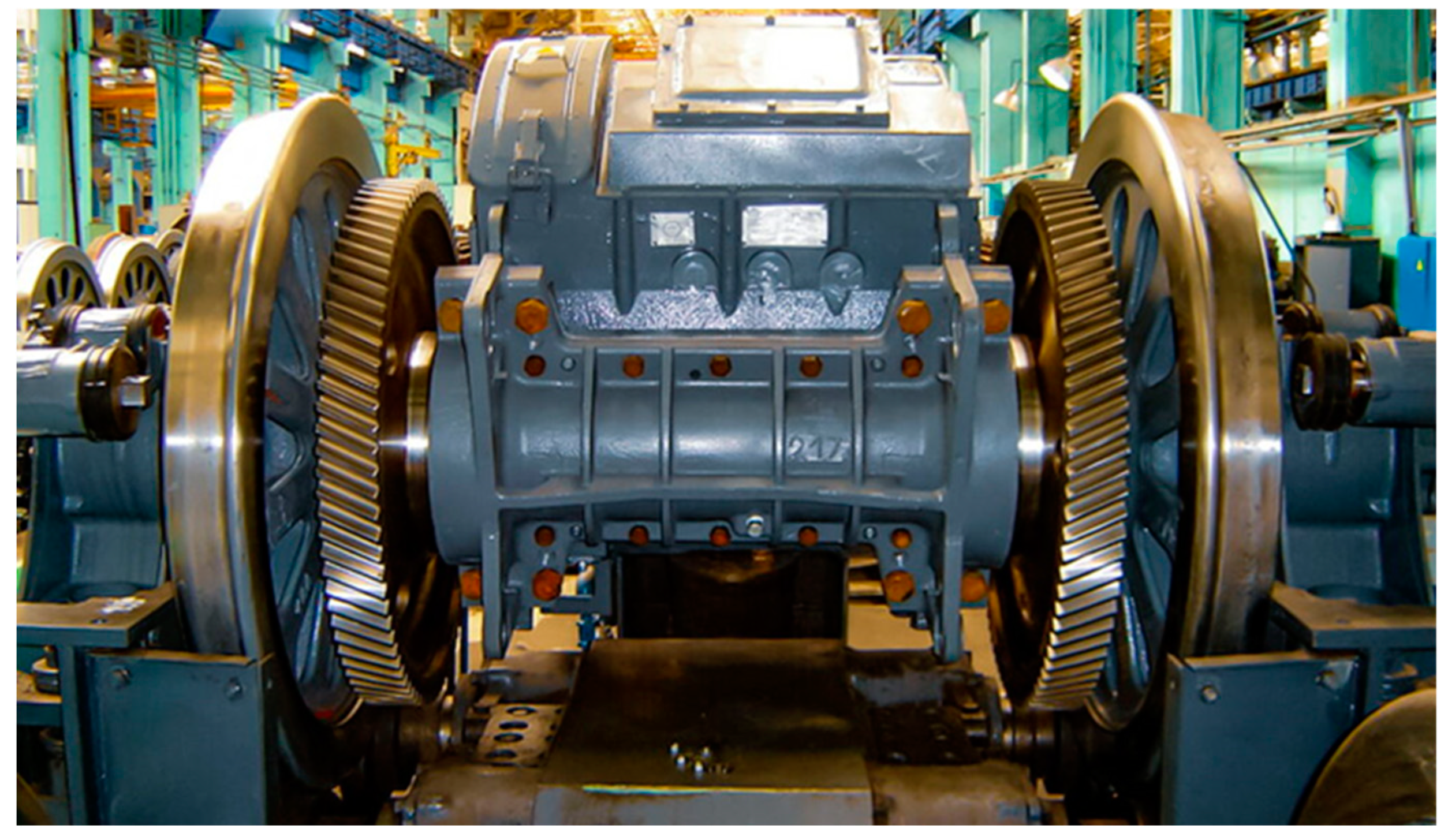
Figure 4.
Calculation scheme for calculation of active surfaces of helical gear wheel teeth on resistance to contact fatigue.
Figure 4.
Calculation scheme for calculation of active surfaces of helical gear wheel teeth on resistance to contact fatigue.
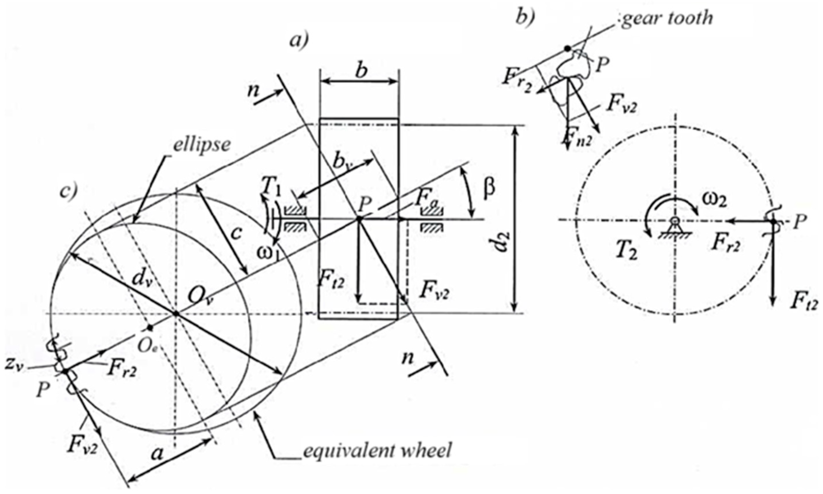

Table 1.
Values of recommended coefficients according to diagnostic parameters .
|
Position of wheels relative to the supports |
Hardness of active tooth surfaces Title 3 |
|
| НВ1 350 or НВ1 and НВ2 350 | НВ1 and НВ2 350 | |
| symmetrical | 0,8…1,4 | 0,4…0,9 |
| Unsymmetrical | 0,6…1,2 | 0,3…0,6 |
| Cantilever | 0,3…0,4 | 0,2…0,25 |
Table 2.
Selection of wheel tooth modulus.
| Construction characteristic | ψ_m= b/m , no more than |
|---|---|
| Highly loaded precision gears, shafts, supports and housings with increased rigidity at НВ: | |
| up to 350 | 45…30 |
| over 350 | 30…20 |
| Conventional gearbox-type transmissions in a separate housing with sufficiently rigid shafts and supports at the НВ: | |
| up to 350 | 30…25 |
| over 350 | 20…15 |
| Rough gears (including those with cantilever shafts) | |
| Rough gears (including those with cantilever shafts) | 15…10 |
Disclaimer/Publisher’s Note: The statements, opinions and data contained in all publications are solely those of the individual author(s) and contributor(s) and not of MDPI and/or the editor(s). MDPI and/or the editor(s) disclaim responsibility for any injury to people or property resulting from any ideas, methods, instructions or products referred to in the content. |
© 2024 by the authors. Licensee MDPI, Basel, Switzerland. This article is an open access article distributed under the terms and conditions of the Creative Commons Attribution (CC BY) license (http://creativecommons.org/licenses/by/4.0/).
Copyright: This open access article is published under a Creative Commons CC BY 4.0 license, which permit the free download, distribution, and reuse, provided that the author and preprint are cited in any reuse.


