

Submitted:
22 October 2024
Posted:
24 October 2024
You are already at the latest version
Abstract
The aim of this research is to present both a sensorless control and a torque derating algorithm in the overload region of a permanent magnet motor for e-bike. First the theoretical backgrounds and the field oriented control are presented. Then a sensorless control, based on the back-emf estimation with a second order generalized integral flux observer for permanent magnet motor, has been designed. The second order generalized integral flux observer is an adaptive filter which can eliminate the DC offset and strongly attenuate the harmonics of the estimated rotor flux. The algorithms have been simulated and then validated by means of tests on a permanent magnet motor for e-bike.
Keywords:
field oriented control
; second order generalized integral flux observer
; Park transformation
; Clarke transformation
; sensorless algorithm
; phase locked loop
; quadrature signal generator
1. Introduction
The widespread use of Electric Vehicles (EVs) in urban areas is inevitable, as the adoption of zero-emission vehicles is becoming mandatory for well-known reasons. This transition will be gradual due to the necessary infrastructure requirements, but it is already recognized that EVs will be the future solution for urban transportation [1]. Surface-mounted permanent magnet (SPM) synchronous motors are an ideal choice for applications demanding high power efficiency. The absence of excitation currents and the high power factor make them highly competitive [2]. Electric vehicles used in urban transportation require immediate and highly effective control to prevent any undesirable situations [3]. In sensored Field Oriented Control (FOC) the rotor position information is provided by a mechanical sensor, which leads to a higher cost and lower reliability [4]. Accurate rotor position is required for both open-loop and closed-loop control. Shaft-mounted sensors face challenges such as mechanical faults, decreased operational reliability, uneven placement of position sensors, and operational failures [5]. However, the mechanical sensors can be replaced with a sensorless algorithm that provides rotor position and speed. The sensorless motor control algorithm is a compelling research area in the motor drive sector. Although motor position sensors are still widely used in most industrial motor drives, cost considerations are driving the industry to eliminate them. Additionally, mounting position sensors on machines is often problematic, especially in specific applications. For instance, in outer rotor machines with limited space, attaching the position sensor to the outer cup rotor is challenging. In drones, where the rotor blade motor is typically a small outer rotor machine, there is no room for a high-accuracy position sensor or even a simple hall sensor [6]. For medium and high speed regions, the most used sensorless algorithm are back-EMF based, where the rotor position is extracted from the fundamental wave of the back-EMF [7]. In this paper, the mathematical equations of the SPM motor in the rotating reference frame are first described. Then, FOC control system and Space Vector Modulation (SVM) technique with sensors is explained. A current loop controller with a sensorless algorithm is designed for the SPM motor based on the given specifications. The back-EMF is estimated using frequency-locked loop and phase-locked loop analysis with a Second Order Integral Flux Observer (SOIFO) filter. Finally, electromechanical speed and position are estimated using the quadrature signal generalized phase-locked loop method. A brief conclusion is drawn by analyzing the results at different loads and speeds.
2. Standard Control of SPM Motor
2.1. Permanent Magnet Synchronous Motor
The Permanent Magnet Synchronous Motor (PMSM) is described by the following equations in the rotating reference frame,
where and are the phase current, and are the phase voltage, respectively. is the electromechanical speed, is the flux linkage produced by the magnets, and are the d-axis and q-axis synchronous inductances and is the phase resistance.
2.2. Field Oriented Control
FOC is the most used control for PMSM. For a given current, maximum torque can be achieved when the stator flux due to the stator current is orthogonal to the rotor flux, created by the PM [8]. Electromagnetic torque is a function of the angle between the stator and rotor flux. The equation that describes the average electromagnetic torque is,
where is the quadrature current, p is the number of pole pairs. Figure 1 shows the FOC architecture. The 3-phase currents and the rotor angle are measured on motor terminals and rotor shaft respectively. The 3-phase currents are converted into a two phase vector frame, and , in the stationary state, using the Clarke transformation, then to the rotating reference frame using the Park transformation [9]. The currents are referred to as direct axis current, , and quadrature axis current, . In order to have the maximum torque for a given current, the current must be fully oriented along the quadrature axis [10]. These two currents are compared to the reference values and the errors are used as input to PI regulators. The control is implemented in the steady state frame, since the currents and voltages are constant. The output of the regulators, which are the direct voltage, , and quadrature voltage, , undergoes the transformation to the stationary reference frame, and the and voltages are used to calculate the inverter duty cycle using the space vector modulation (SVM).
The FOC consists in controlling the stator currents and the torque. The idea behind the operation is the transformation from a three-phase time dependent system into a two coordinate system [11].
2.3. Space Vector Modulation
SVM is a modulation technique able to generate the desired phase voltages [12]. Since only one mosfet is ON and the other is OFF in each leg, there are 8 possible combinations. The phase vectors divide the plan into 6 sectors, each spanning . Depending on the sector addressing the desired phase voltage, two adjacent vectors are applied in succession. The two vectors are time weighted in a switching period to produce the desired output voltage. Let’s assume the desired voltage is in the first sector , the following condition holds
where and are the times in which the vectors and are applied respectively, is the time in which the zero vector is applied. By splitting the above equation in real and imaginary parts it is
Finally, since , the times can be written as
3. Methodology
The algorithms have been simulated and then validated with the use of the dSpace MicroLabBox platform. SPM motor parameters are given in Table 1.
3.1. Current Loop Design
Figure 2 and Figure 3 show the block diagrams related to the current control loop in the synchronous reference frame. If the electric motor is isotropic then [13]. In the control loops the term and the term has been added to and respectively, in order to decouple the two dynamics. If the time constant introduced by the inverter is negligible with respect to the electric time constant of the motor and , then the terms added to the voltages will cancel those in the motor block diagrams [14]. In order to better control the dynamic of the current loop, also the term is added to compensate the effect of the back-EMF. The open loop transfer function related to the current loop is then
The bandwidth is fixed to and the phase margin to . The regulator gains that have been calculated from those specifications are and .
3.2. Sensorless Algorithm
The current and voltage are filtered and filtered-integrated by a Second Order - Second order Generalized Integrator (SO-SOGI), which is a forth order adaptive filter, and they are going to be used to estimate and , which will be used to extract the rotor position. The overall structure is called Second Order Integral Flux Observer (SOIFO) and has strong attenuation capability against the dc offset and harmonics.
3.2.1. Back-emf
The voltage and flux equations of a PMSM motor in coordinate can be described by the following equations [15].
where is the stator voltage vector, is the stator current vector, is the stator flux vector, is the stator inductance, is the stator resistance, is the rotor electrical position and is the rotor flux linkage. The PMSM sensorless control based on the rotor flux observation is shown in Figure 4, where and are the estimated electromechanical position and the speed.
From (8) the following equation can be obtainted
The error due to the integral initial value of the estimated rotor flux is calculated as
On top of that, other errors will be introduced due to parameters mismatch, unknown integral initial value, measurements error, inverter nonlinearities etc. Then the following equation can be obtained
where and are the parameter variation, is the initial back-EMF vector and represents other errors.
3.3. Frequency Locked Loop
The frequency locked loop is a control loop used to auto-adapt the center frequency of the SOGI filter to the fundamental input frequency [16]. Figure 5 shows the architecture of the FLL. The transfer function between the error and the input signal is
The transfer function is a notch filter with unity gain at the centre frequency. The phase angle of this transfer function experiences a phase jump of when the frequency of the input signal goes from lower to higher to that of the estimated of the FLL. Figure 6 shows that the transfer function and are in phase when the frequency of the input signal is lower than that of the FLL (), and are in phase opposition otherwise (). A new variable is defined as the product between and . This variable will be positive when , 0 when and negative when . Based of these considerations, the FLL can be designed using this frequency error as the input to a negative gain and an integrator. In this way, if there is a mismatch between the input frequency and the FLL frequency, this control loop will drive the FLL frequency up to the input frequency. Also, in order to accelerate the dynamic, the centre frequency can be added as a feed-forward variable, since the magnitude of the input of the FLL decreases as the two frequencies differ, as shown in Figure 6.
3.4. Phase Locked Loop Analysis
Let’s assume the input signal is given by:
and the output signal is given by:
then the output of the phase multiplier can be written as:
If the PD regulator of the PLL is a multiplier it is necessary to choose the bandwidth of the system low enough to attenuate the high frequency term, and so only the DC term remains:
Assuming that the is tuned to the input frequency, , then the PD error is further simplified into
As a last step, assuming that the phase error is low, , the output of the PD regulator can be linearized in the vicinity of that operating point because . The result
Assuming V=1, the open loop transfer function in the Laplace domain is
and the closed loop transfer function is
The closed loop transfer function can be normalized in the following way
where
The response time of this second-order system, from the start of the variation to the 99% of the steady-state final value, can be approximated through
3.5. Second Order Integral Flux Observer Architecture
In the SOIFO, there are four SO-SOGI-FLL that have the following quantities as input: , , and . The output of those SO-SOGI-FLL will be the filtered and the integrated filtered input. In this way, the following quantities can be computed
Figure 7 show the architecture of the two SOIFO, where and represents the filtered variables. and are used as the input of the QSG-PLL, described hereafter as shown in Figure 8, and the estimated speed and estimated position are obtained.
3.6. Quadrature Signal Generator - Phase Locked Loop
There is a high frequency term in the output of the phase detector. In order to attenuate the effect of this term on the angular velocity and angular position the bandwidth of the control loop must be decreased [17]. A trade-off arises, because a decrease of bandwidth leads to an increase of the settling time. Because of this, a new PLL scheme called Quadrature Signal Generator PLL (QSG-PLL) is introduced in Figure 8. Referring to Figure 8, if and , the new output of the phase detector can be calculated as
where and are the estimated variables of the PLL. In this way, the high frequency term disappears, and the bandwidth of the control loop can be increased. Also, a normalization block is introduced to make the bandwidth of the control loop independent from the amplitude of the input signals.
4. Results
The electric angular frequency of the back-EMF at which the sensorless algorithm is started has been chosen as , which is about . By resorting to the design procedure explained in Section 3.3, the settling time has been chosen as and the damping ratio as , which leads to an overshoot of . The undamped natural frequency is then . Finally, the gains mentioned in Figure 5 are computed as and .
4.1. Second Order - Second Order Generalized Integrator dynamic
4.2. Second Order - Second Order Generalized Integrator filtering
In this section the filtering capabilites of the sensorless algotithm are described. Figure 13 and Figure 14 show the Bode diagram of variable and , mentioned in Figure 5 respectively. Figure 13 shows that the slope is -20dB/dec when and -60dB/dec when . Instead, Figure 14 shows that the slope is -40dB/dec when and -40dB/dec when . The DC gain in the results are almost and not perfectly 0 due to the sampling. In the center frequency the gain is 1 and at high frequency the attenuation is as expected by the Bode diagrams.
4.3. Quadrature Signal Generator - Phase Locked Loop
The time response of the QSG-PLL has been set to . This constrain leads the parameters of the PLL to be and . When the motor is accelerating, a static position error will appear while there will not be a static velocity error. That is because of applying a quadratic ramp to a Type two system. The static error can be calculated as , where is the electrical acceleration and is the integral gain of the PI controller. Assuming a maximum mechanical acceleration of , which corresponds to electrical acceleration the maximum error will be , that is negligible.
Figure 15 shows the time response of the estimated speed after a frequency step variation of 20%. The time response is about 100ms as designed.
4.4. Steady-State
This section describes the steady-state performance of the sensorless algorithm at
- low speed: , which is about
- medium speed: , which is about
Figure 16, Figure 17 and Figure 18 show the effect of the speed oscillation due to the cogging torque. Figure 18 and Figure 19 show that the flux linkage moves along a circle centered in (0,0), because the dc component of the and emf are effectively rejected. Figure 20 and Figure 21 show the steady state angle error at low and medium speed. The maximum error of angle estimation is 0.25 rad when = 25 rad/s, and 0.12 rad when = 250 rad/s. One part of this error is due to the sampling delay. It can be estimated by in the worst case, where T is the sampling delay which is , since and . At the angular error due to the sampling delay is then , which is about and at is about , which is . The error due to the sampling delay is then negligible at low and medium speed, and the main factor of the angle error is parameter mismatch.
4.5. Dynamic
This section deals with the performance of the sensorless algorithm during a variation of the speed reference and a variation of the load torque. Figure 22 and Figure 23 show the results after a step variation of the reference from 100 to and vice versa. The results show the stability of the sensorless algorithm even after a fast variation. The maximum angle error is . Figure 24 and Figure 25 show the results after a step load variation of the and vice versa. The results show the stability of the sensorless algorithm even after a fast torque variation. The maximum angle error is .
5. Conclusions
In this paper, a sensorless algorithm is designed for a PM synchronous motor using an advanced second order-second order generalized integrator filter and a quadrature signal generator phase locked loop controller is used to estimate the rotor position from the filtered output.
The sensorless algorithm is initiated at 25 rad/s electrical angular frequency of the back-emf, that corresponds to 48rpm.
- Low speed: , approximately
- Medium speed: , approximately
A negligible error of is recorded at a maximum mechanical acceleration of , with as input of SO-SOGI, where and . The time response of the estimated speed is approximately 100ms after a frequency step variation of 20%. In the steady-state performance of the sensorless algorithm, the maximum error in angle estimation is at , and at . Part of this error is due to the sampling delay. It can be estimated by in the worst case, where T is the sampling delay of , given that and . At , the angular error due to the sampling delay is , approximately , and at , it is about , or . Thus, the error due to the sampling delay is negligible at both low and medium speeds. Stability of the motor during rapid variation of the reference speed and load torque shows the performance of the sensorless algorithm. The maximum angle error during a fast variation is . Similarly, the algorithm remains stable after rapid torque variations, with the maximum angle error of .
Author Contributions
Following are the authors contribution to this work: A.P. Formal analysis, investigation, data curation, editing and prepration of the final draft were caried out by Engr.Abdin pasund. P.F.S. The methodology, software and the validation were handled by Engr.Pier Francesco Sartori and the initial draft is prepared by P.F.S.; N.B.—The research concept was developed by professor Dr.Nicola bianchi, who also provided the necessary resources for the simulation and testing equipment. Dr.Bianchi served as the supervisor, reviewer and the editor of this article.
Acknowledgments
We are grateful to all the colleagues at the Electric Drive Laboratory (EDLAB) for their invaluable support in the preparation of this article.
Abbreviations
The following abbreviations are used in this manuscript:
| EVs | Electric vehicles |
| PM | Permanet magnet |
| SPM | Surface mounted permanent magnet |
| FOC | Field oriented control |
| EMF | Electromotive force |
| SVM | Space vector modulation |
| SOIFO | Second-order integral flux observer |
| SO-SOGI | Second-order second-order generalized integral |
| PMSM | Permanent magnet synchronous motor |
| PI | Proportional integral |
| FLL | Frequency locked loop |
| PLL | Phase locked loop |
| QSG-PLL | Quadrature signal generated phase locked loop |
References
- Vagati, A.; Pellegrino, G.; Guglielmi, P. Comparison between SPM and IPM motor drives for EV application. In Proceedings of the The XIX International Conference on Electrical Machines - ICEM 2010; 2010; pp. 1–6. [Google Scholar]
- Bianchi, N.; Bolognani, S.; Frare, P. Design criteria for high-efficiency SPM synchronous motors. IEEE Transactions on Energy Conversion 2006, 21, 396–404. [Google Scholar] [CrossRef]
- Vu, N.T.; Choi, H.H.; Kim, R.Y.; Jung, J.W. Robust speed control method for permanent magnet synchronous motor. IET electric power applications 2012, 6, 399–411. [Google Scholar] [CrossRef]
- Xin, Z.; Wang, X.; Qin, Z.; Lu, M.; Loh, P.C.; Blaabjerg, F. An improved second-order generalized integrator based quadrature signal generator. IEEE Transactions on Power Electronics 2016, 31, 8068–8073. [Google Scholar] [CrossRef]
- Mukherjee, P.; Paitandi, S.; Sengupta, M. Sensorless speed control of a laboratory fabricated SPM-BLDC motor prototype. Sādhanā 2023, 48, 236. [Google Scholar] [CrossRef]
- Sun, L.; Li, X.; Chen, L. Motor Speed Control With Convex Optimization-Based Position Estimation in the Current Loop. IEEE Transactions on Power Electronics 2021, 36, 10906–10919. [Google Scholar] [CrossRef]
- Xu, W.; Jiang, Y.; Mu, C.; Blaabjerg, F. Improved nonlinear flux observer-based second-order SOIFO for PMSM sensorless control. IEEE Transactions on Power Electronics 2018, 34, 565–579. [Google Scholar] [CrossRef]
- Jiang, Y.; Xu, W.; Mu, C. Improved SOIFO-based rotor flux observer for PMSM sensorless control. In Proceedings of the IECON 2017-43rd Annual Conference of the IEEE Industrial Electronics Society. IEEE; 2017; pp. 8219–8224. [Google Scholar]
- Teodorescu, R.; Liserre, M.; Rodriguez, P. Grid synchronization in singlephase power converters 2007.
- Schenke, M.; Wallscheid, O. A deep Q-learning direct torque controller for permanent magnet synchronous motors. IEEE Open Journal of the Industrial Electronics Society 2021, 2, 388–400. [Google Scholar] [CrossRef]
- Öztürk, N.; Celik, E. Speed control of permanent magnet synchronous motors using fuzzy controller based on genetic algorithms. International Journal of Electrical Power & Energy Systems 2012, 43, 889–898. [Google Scholar]
- Devi, G.R.; Rajambal, K. Novel space vector pulse width modulation technique for 5-Phase voltage source inverter. In Proceedings of the 2018 IEEE International Conference on System, Computation, Automation and Networking (ICSCA). IEEE; 2018; pp. 1–9. [Google Scholar]
- Lee, Y.H.; Hsieh, M.F. Swiveling Magnetization for Anisotropic Magnets for Variable Flux Spoke-Type Permanent Magnet Motor Applied to Electric Vehicles. Energies 2022, 15, 3825. [Google Scholar] [CrossRef]
- Shen, H.; Luo, X.; Liang, G.; Shen, A. A robust dynamic decoupling control scheme for PMSM current loops based on improved sliding mode observer. Journal of Power Electronics 2018, 18, 1708–1719. [Google Scholar]
- Song, Y.; Song, Z.; Yao, X. Permanent Magnet Synchronous Motor Control Based on New Sliding Mode Observer. In Proceedings of the Journal of Physics: Conference Series. IOP Publishing; 2022; Vol. 2218, p. 012058. [Google Scholar]
- Huang, Y.; Tao, T.; Liu, Y.; Chen, K.; Yang, F. DSC-FLL based sensorless control for permanent magnet synchronous motor. Progress In Electromagnetics Research M 2020, 98, 171–181. [Google Scholar] [CrossRef]
- Zheng, Y.; Chang, Y.; Liu, D.; Wang, H.; Zuo, Y.; Ge, X. Sensorless Control of Permanent Magnet Synchronous Motor Based on Finite-Position-Set-Phase-Locked Loop. In Proceedings of the 2022 IEEE 5th International Electrical and Energy Conference (CIEEC). IEEE; 2022; pp. 2790–2795. [Google Scholar]
Figure 1.
FOC architecture
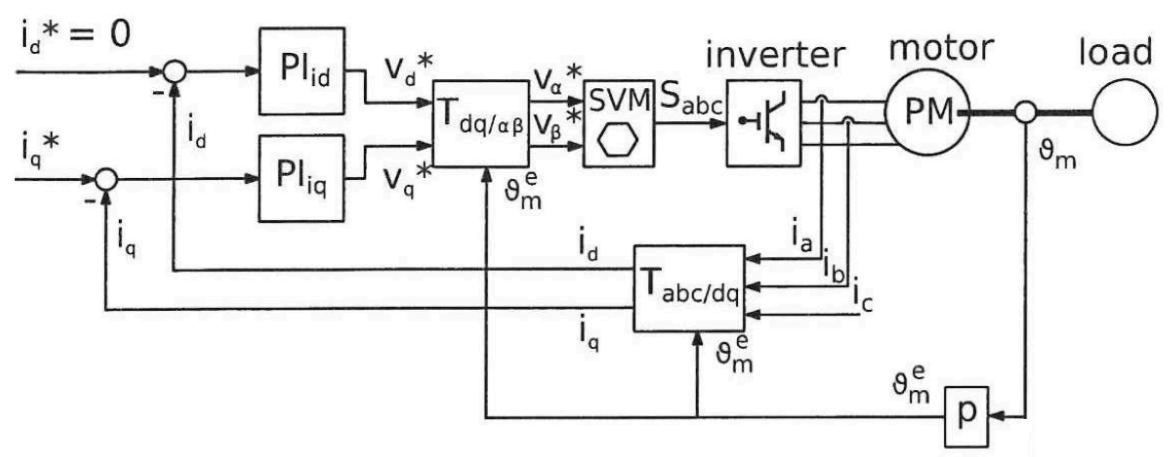
Figure 2.
Simplified block scheme of current loop
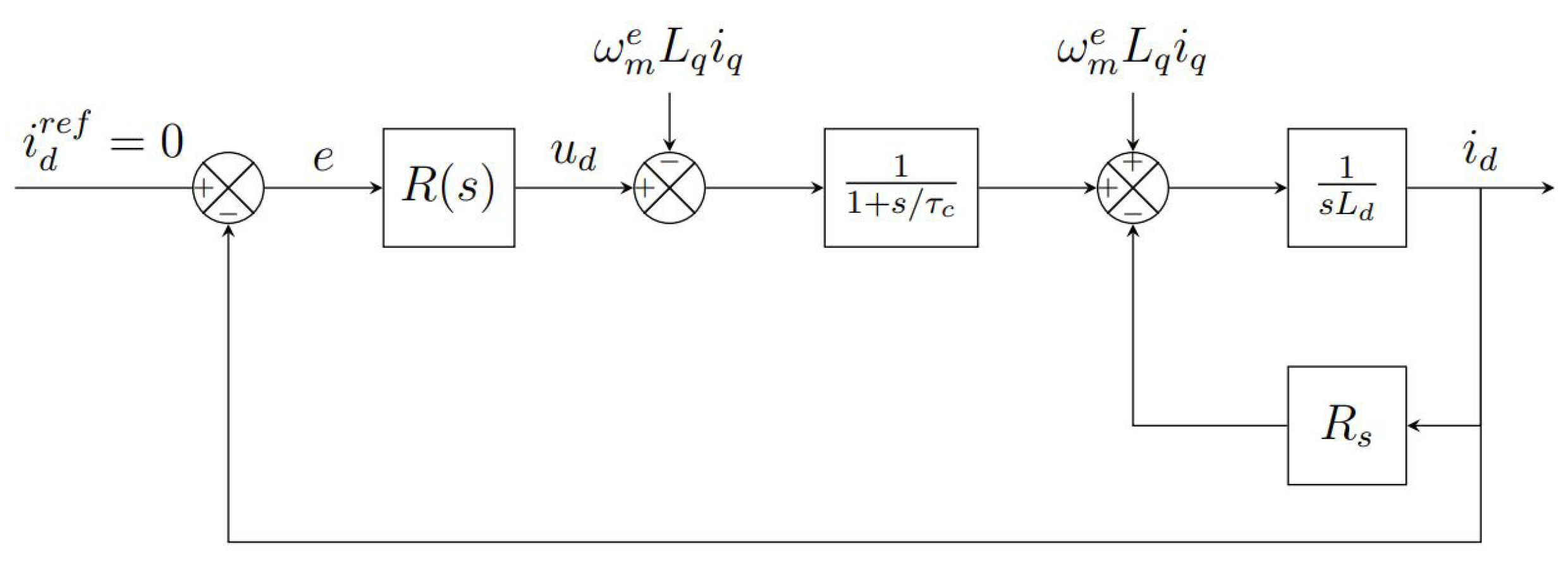
Figure 3.
Simplified block scheme of current loop
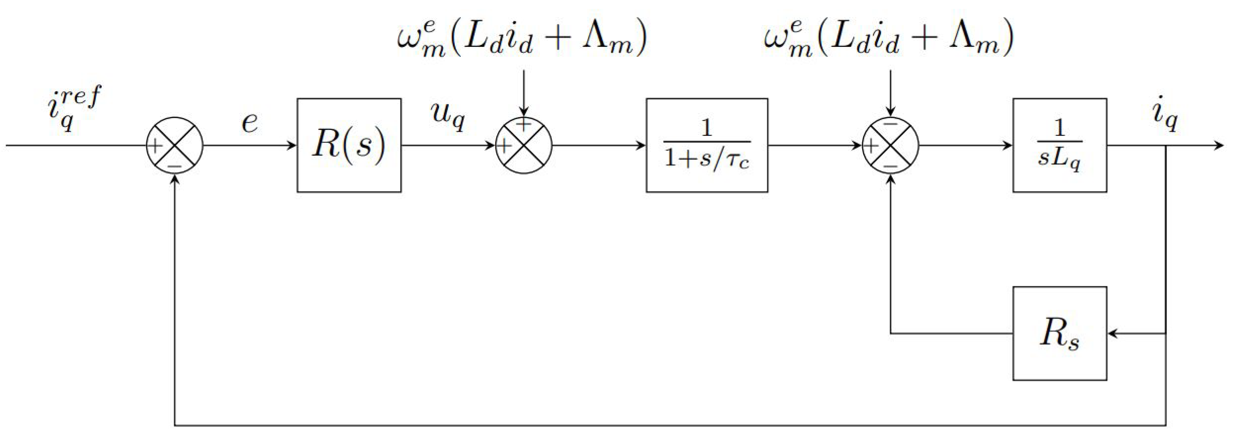
Figure 4.
Rotor flux observation
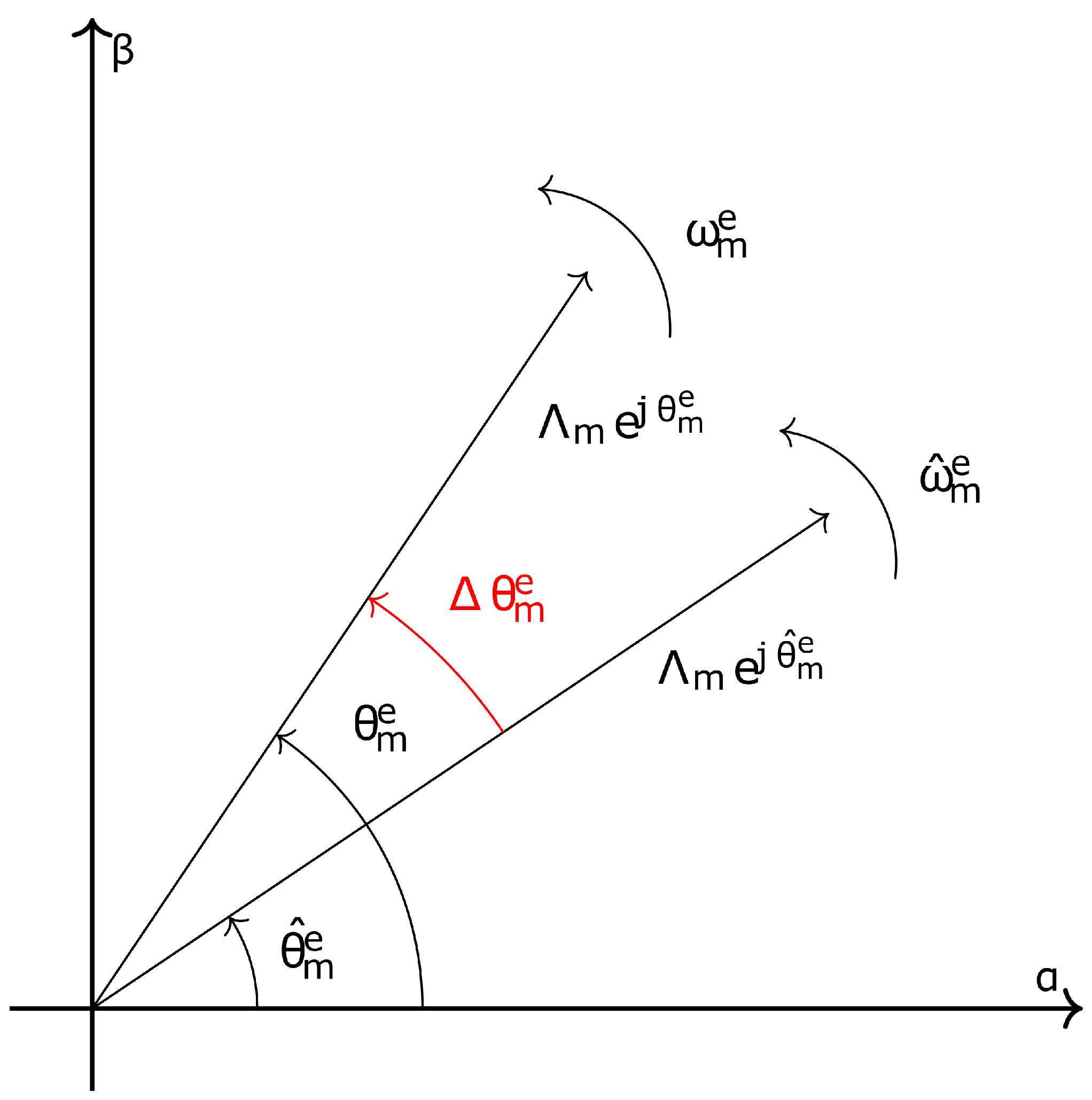
Figure 5.
SO-SOGI-FLL block diagram
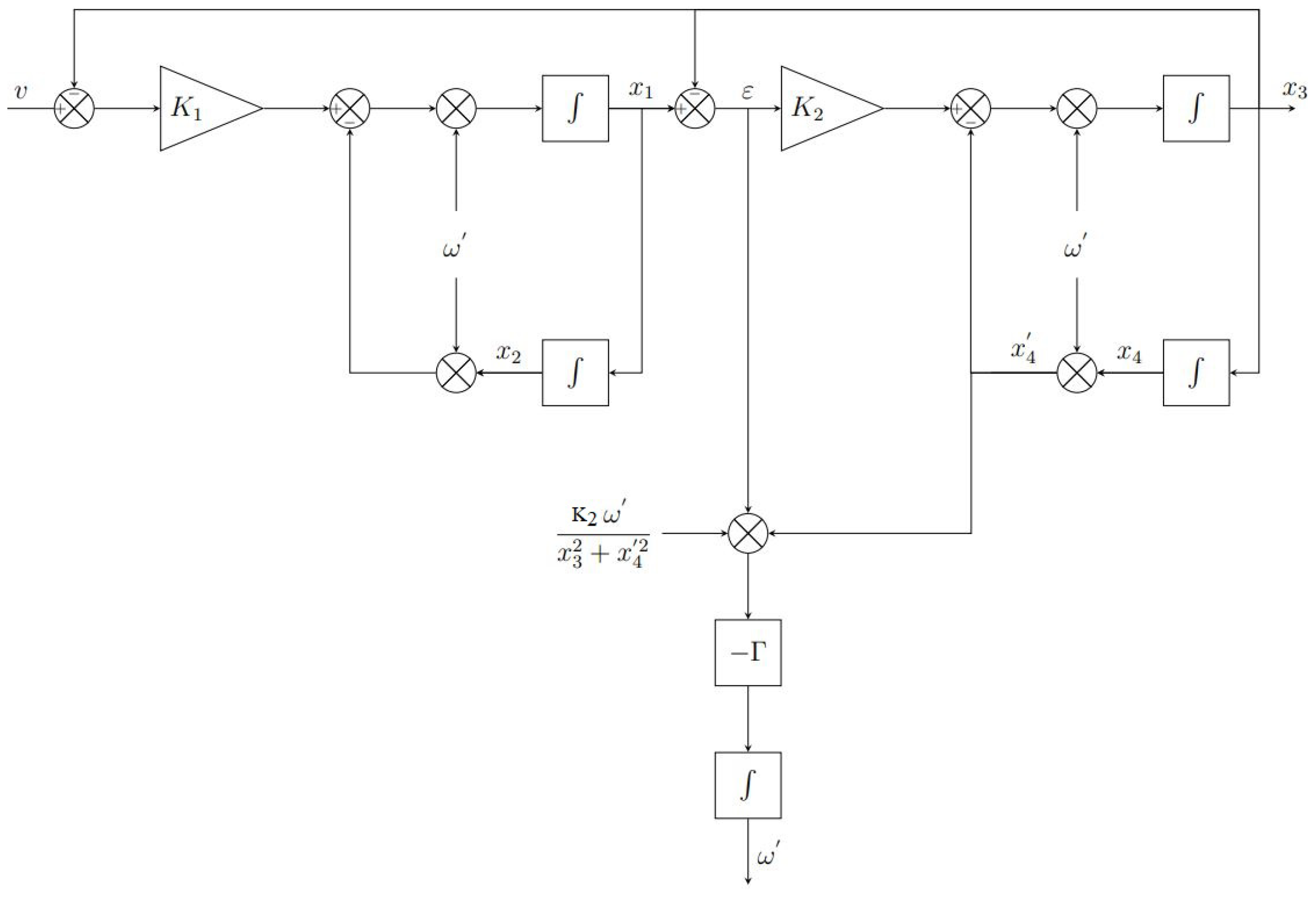
Figure 6.
Bode diagrams of and
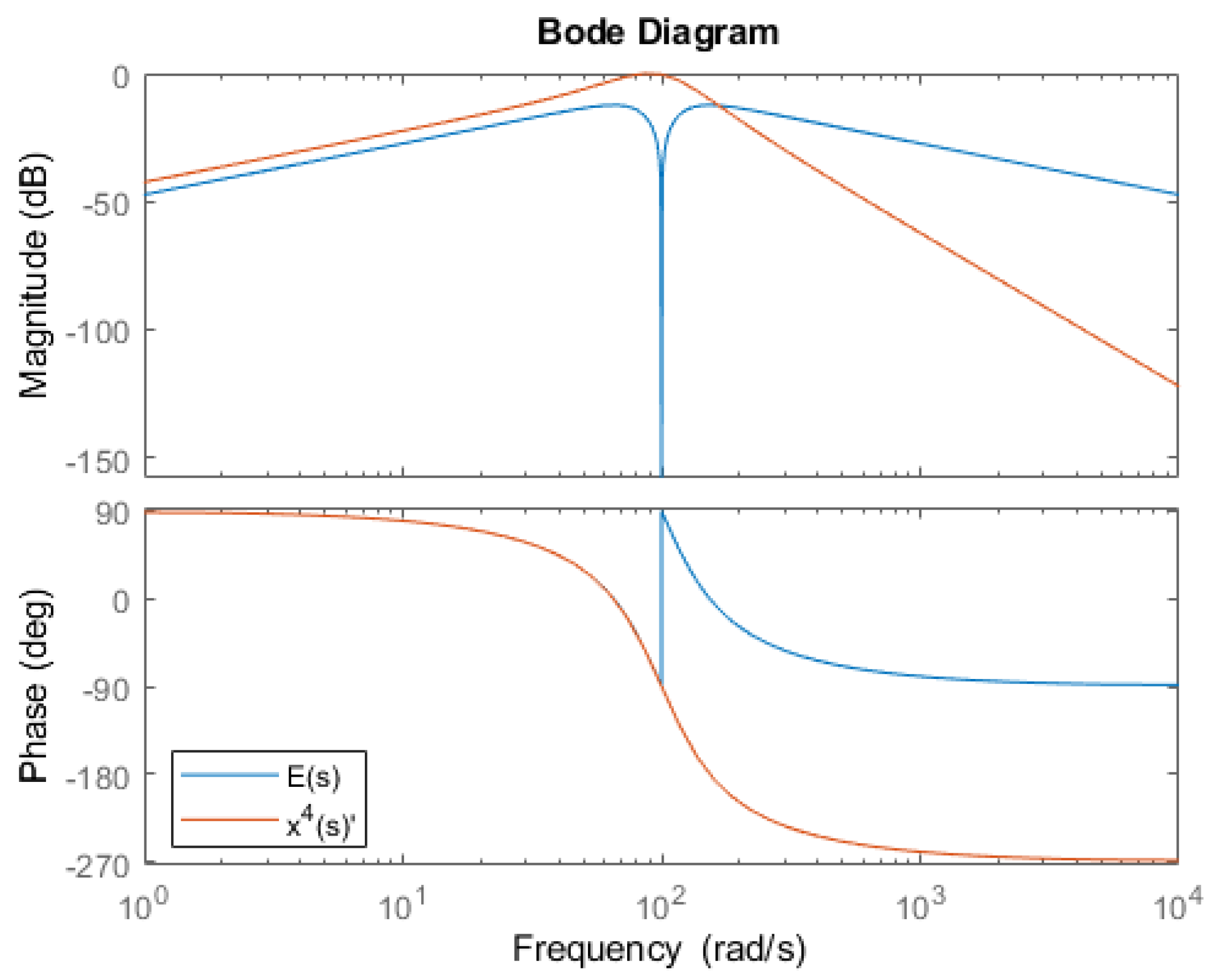
Figure 7.
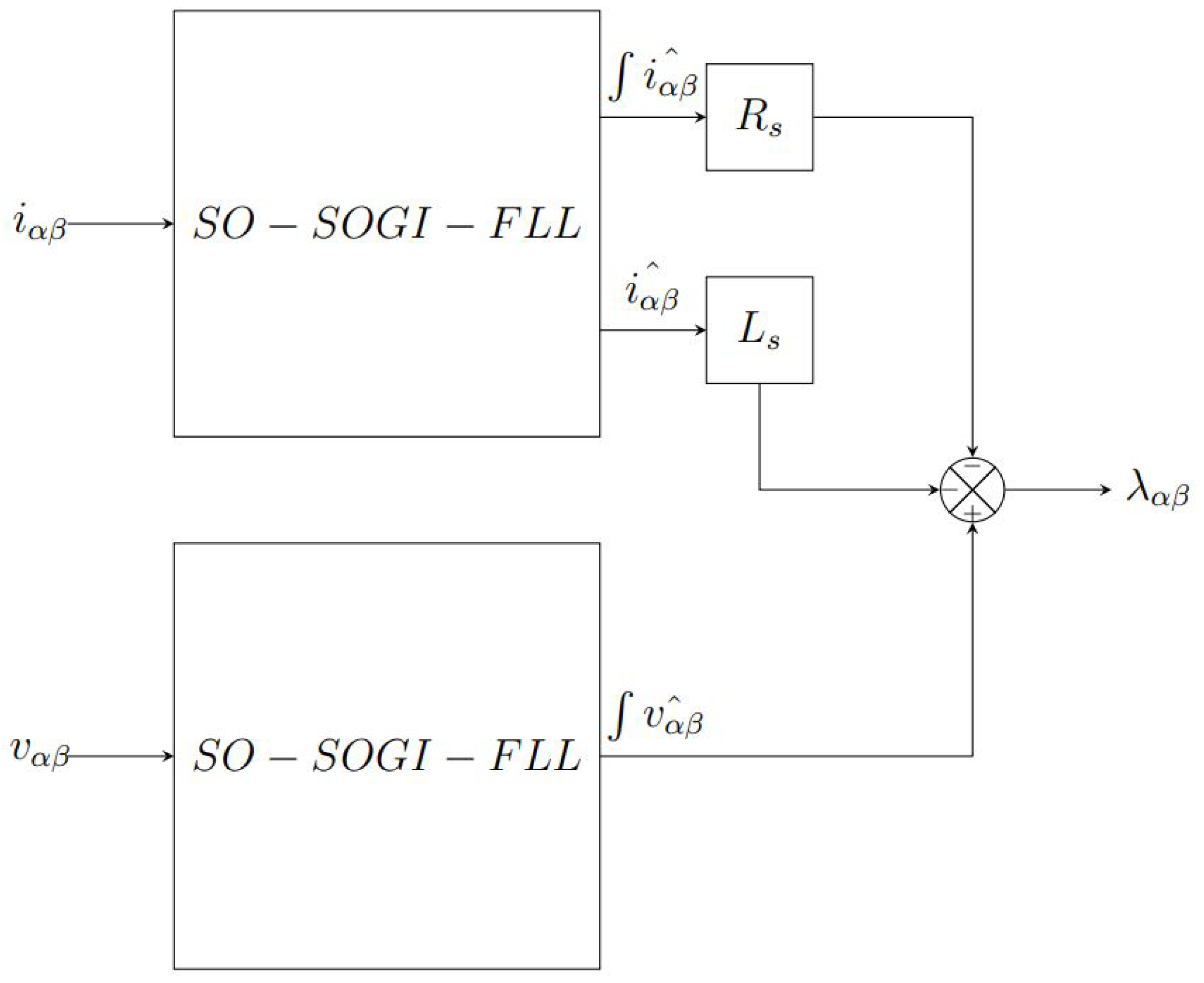
Figure 8.
QSG-PLL block diagram
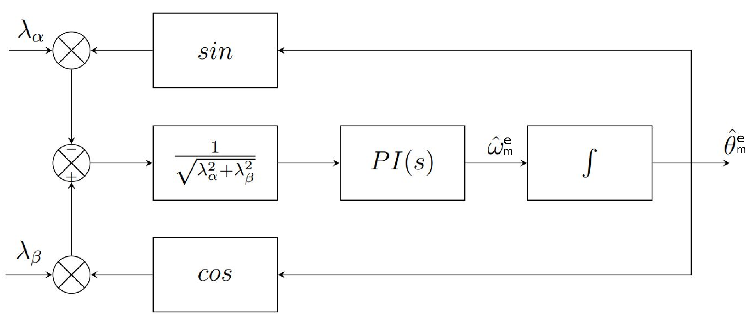
Figure 9.
Measured and over time after a 20% step variation of amplitude
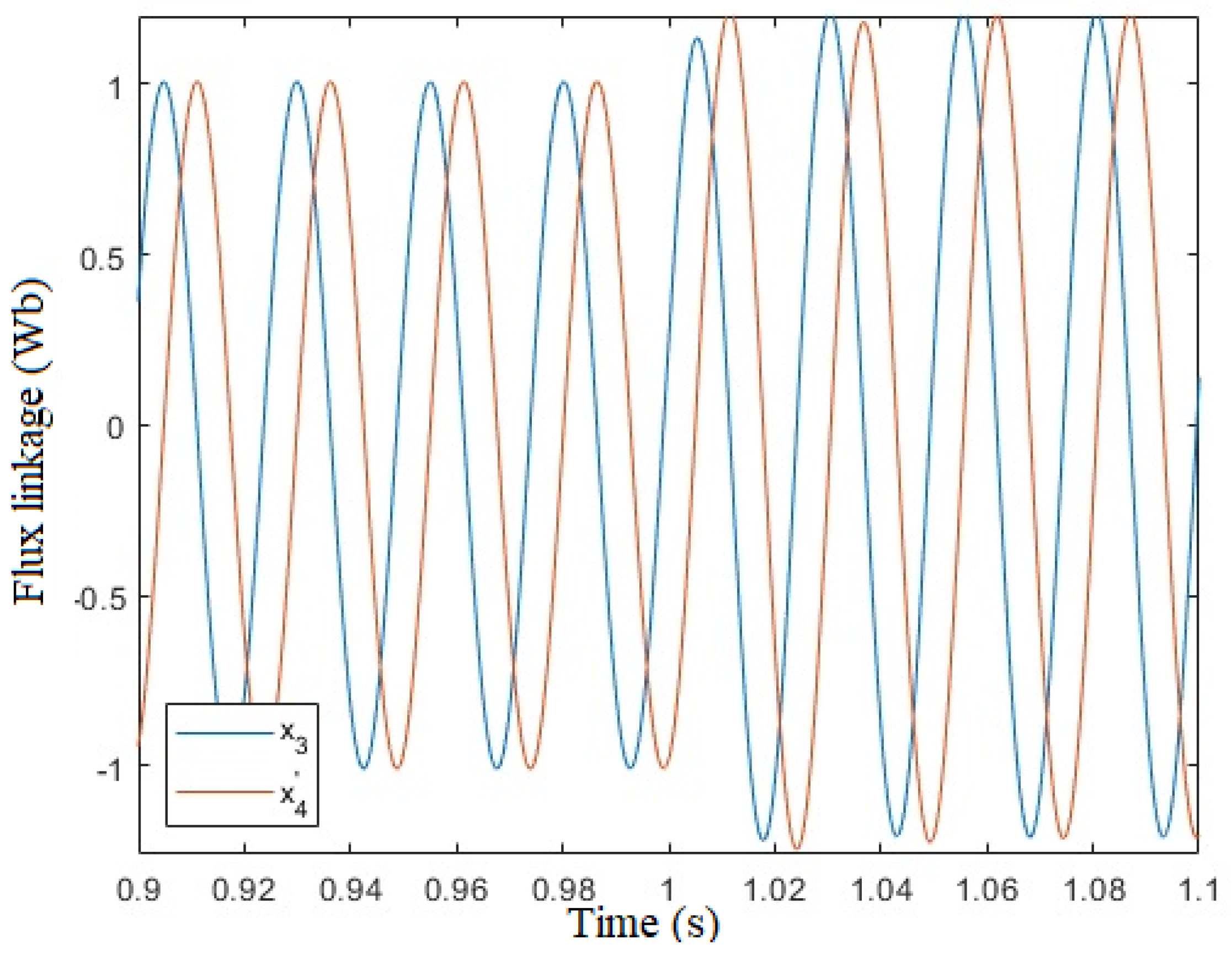
Figure 10.
Measured over time after a 20% step variation of amplitude
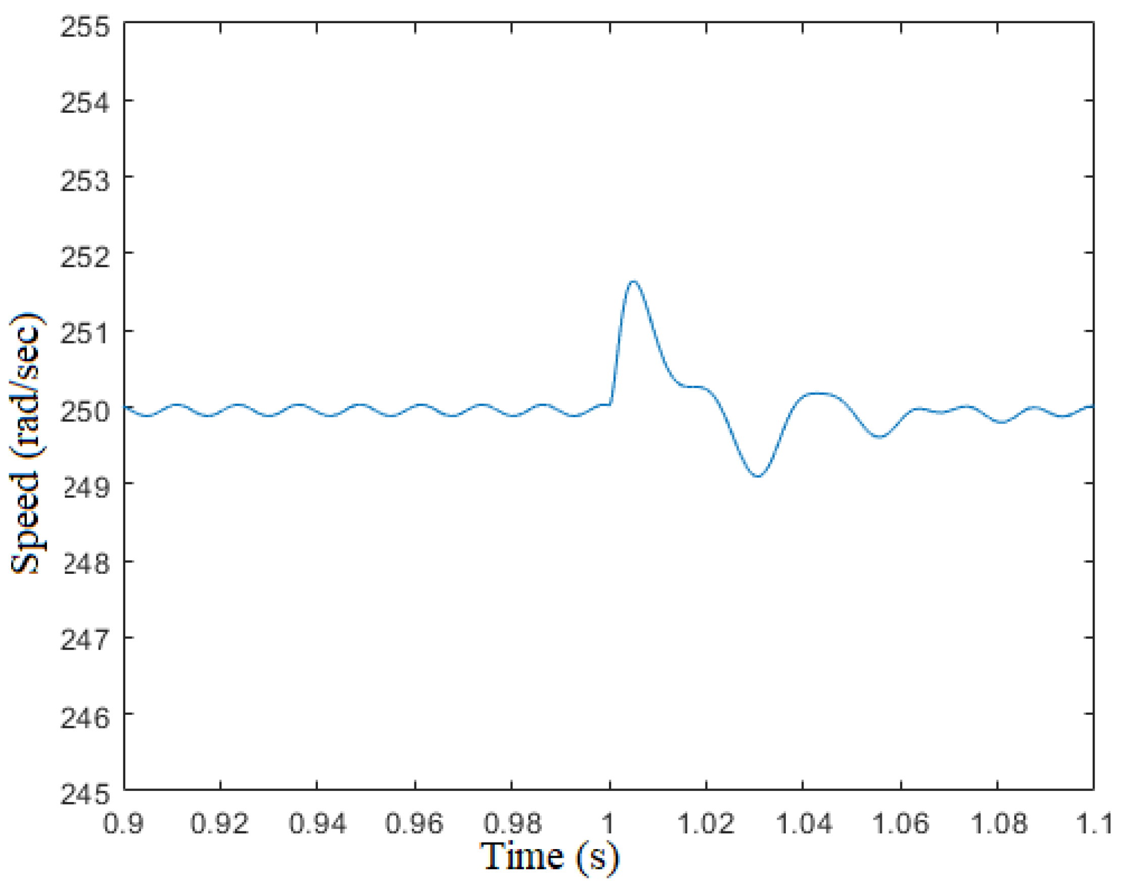
Figure 11.
Measured and over time after a 20% step variation of frequency
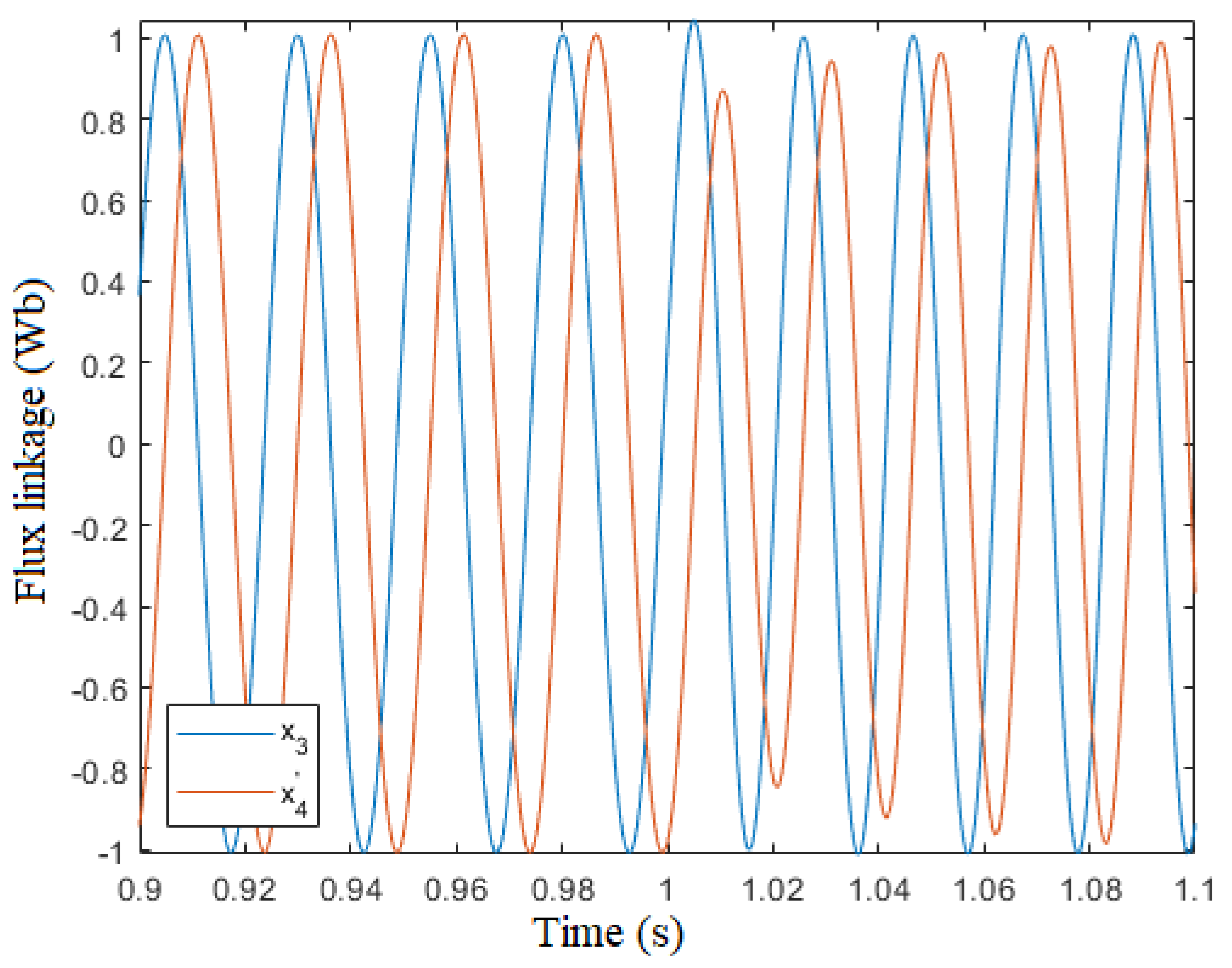
Figure 12.
Measured over time after a 20% step variation of frequency
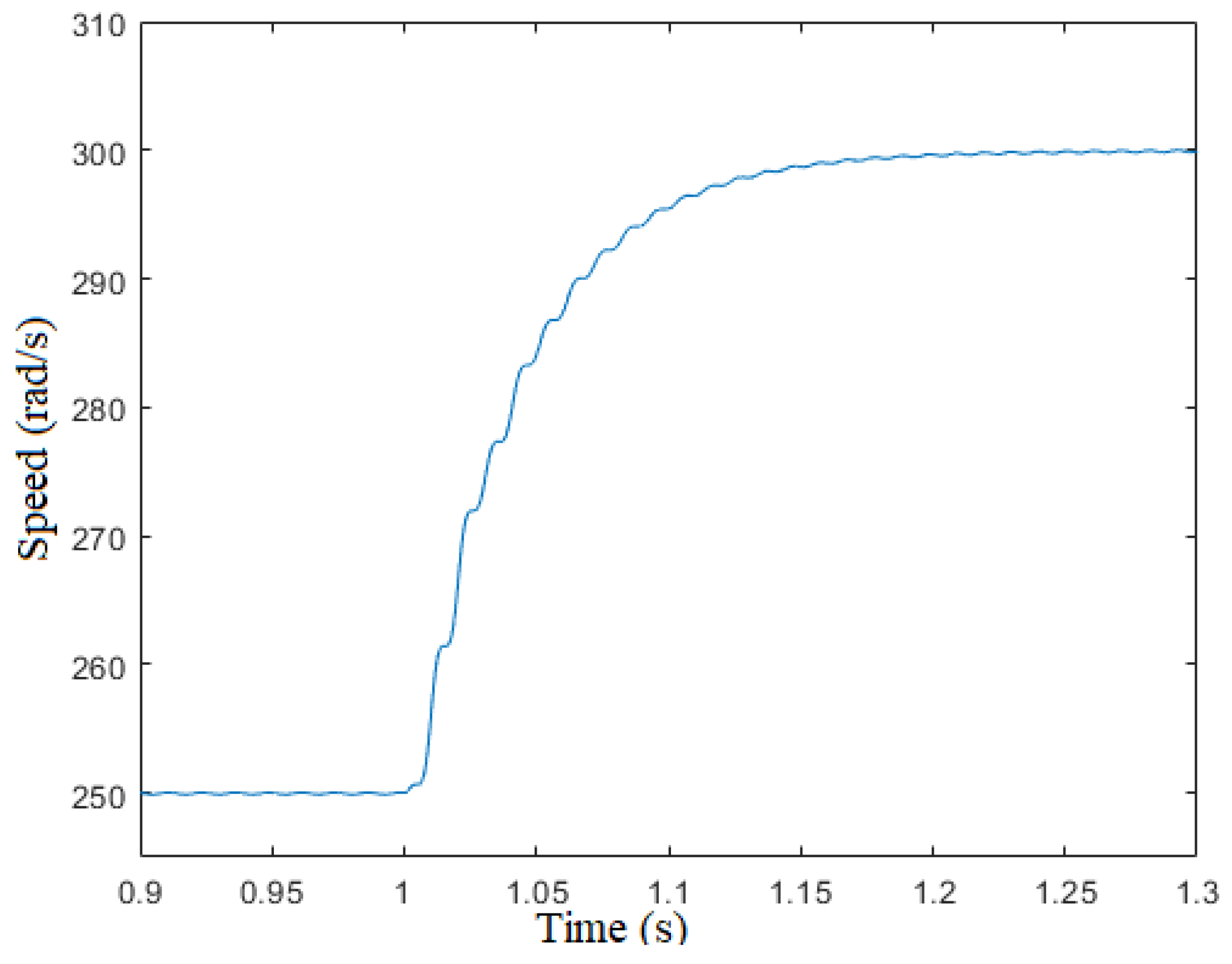
Figure 13.
Bode diagram of
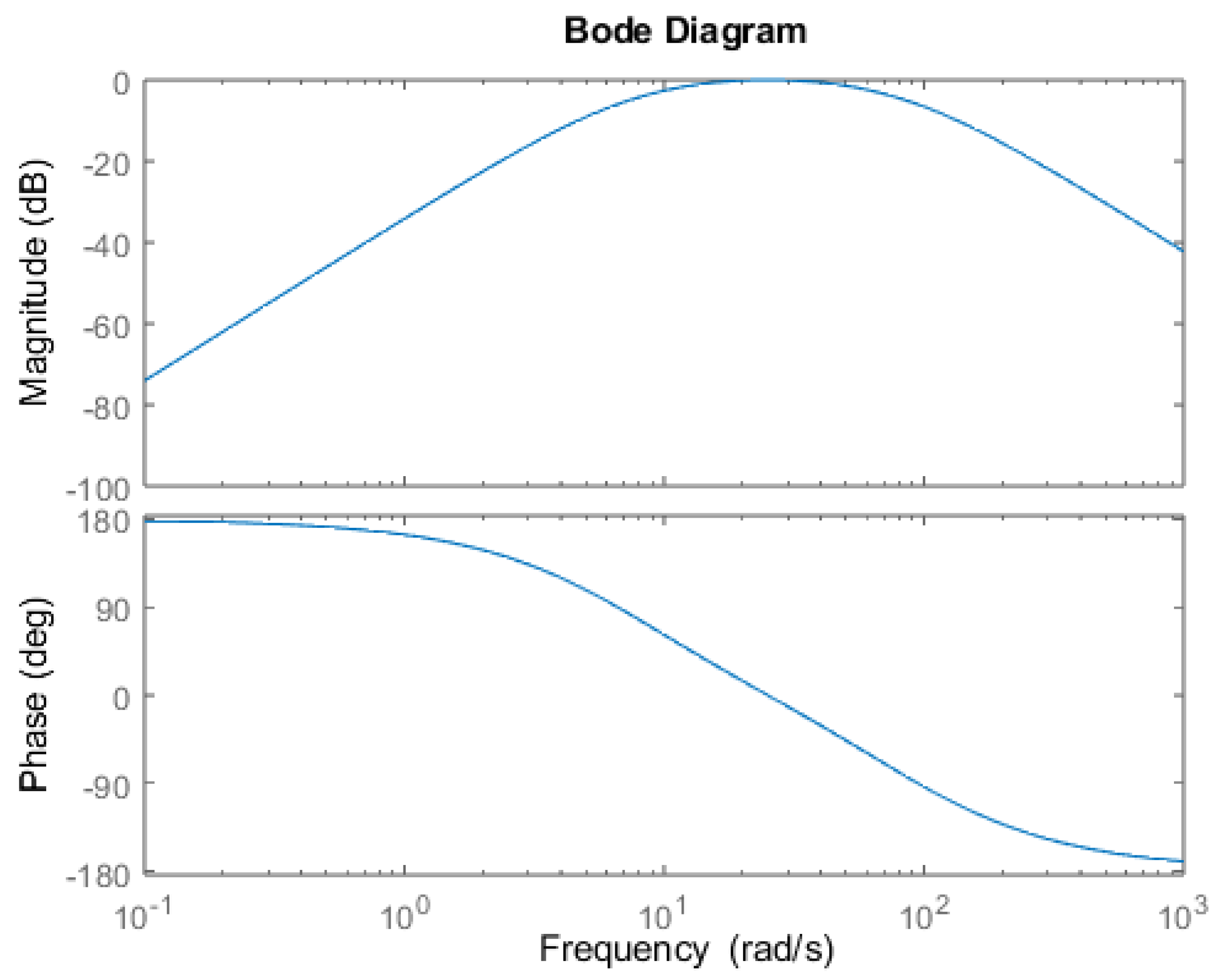
Figure 14.
Bode diagram of
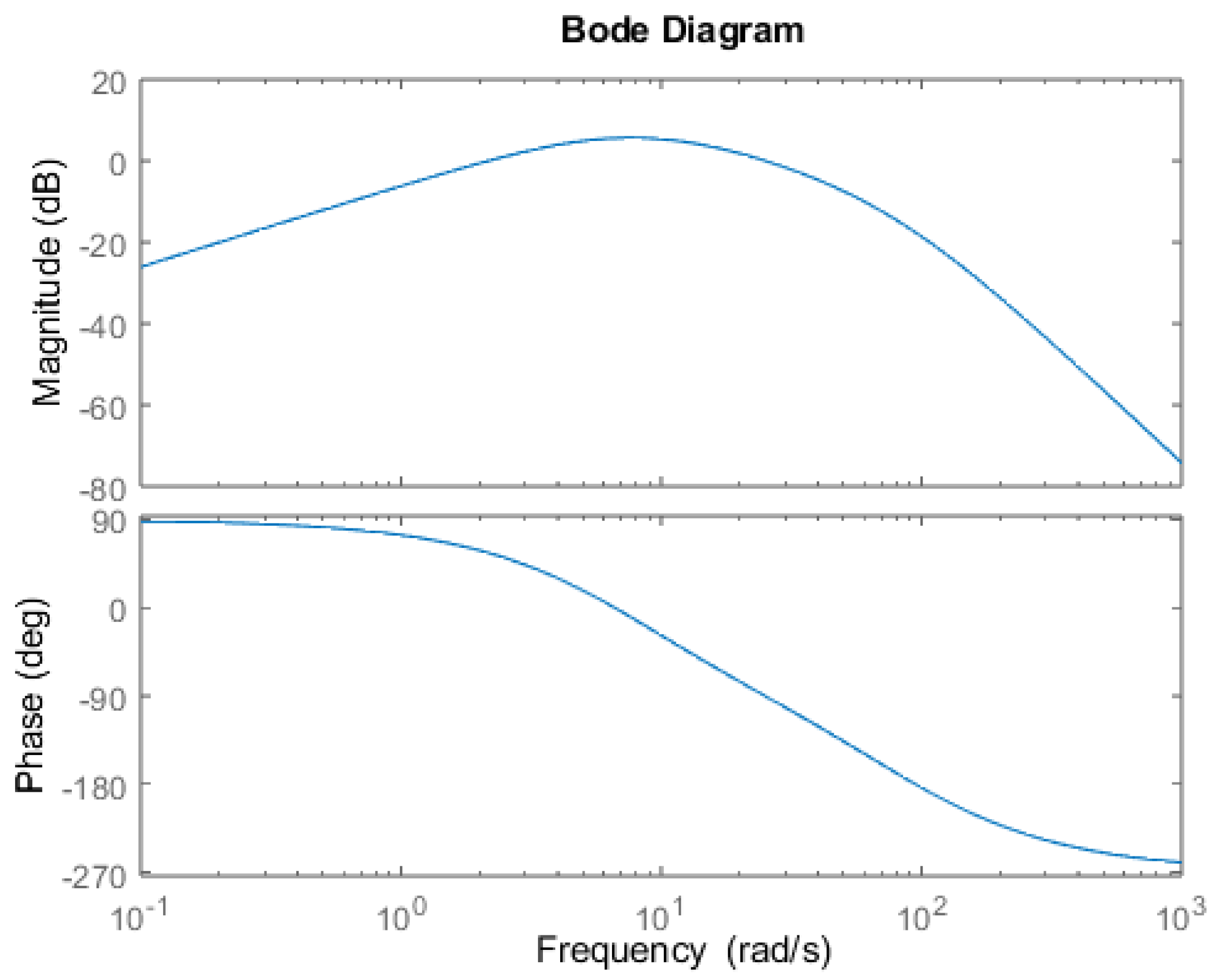
Figure 15.
Measured over time
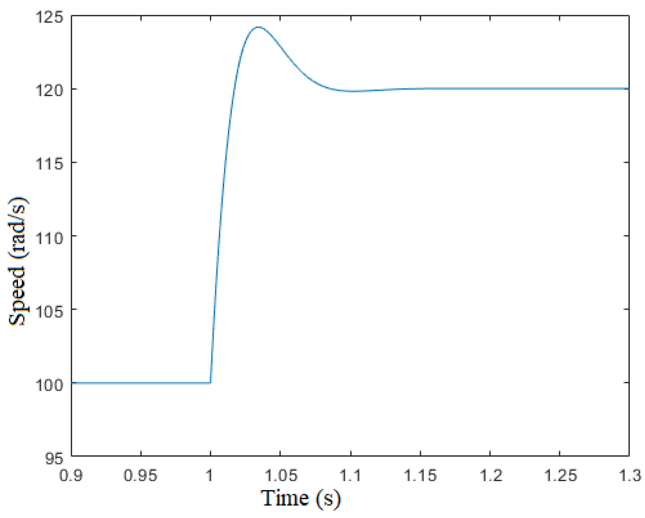
Figure 16.
Measured and vs time ()
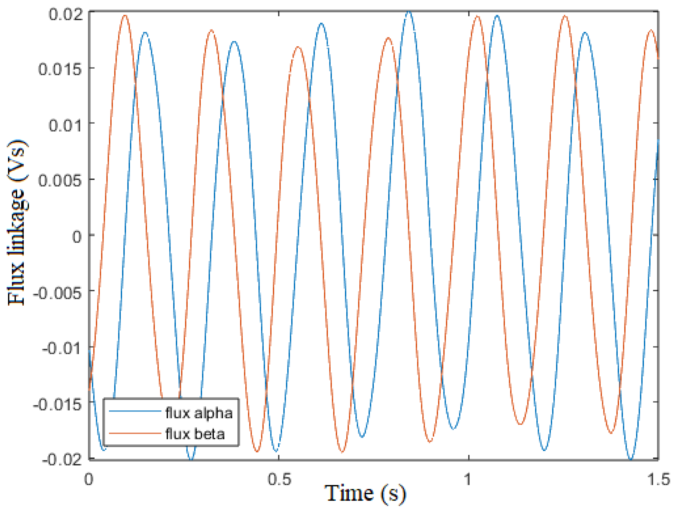
Figure 17.
encoder and sensorless vs time ()
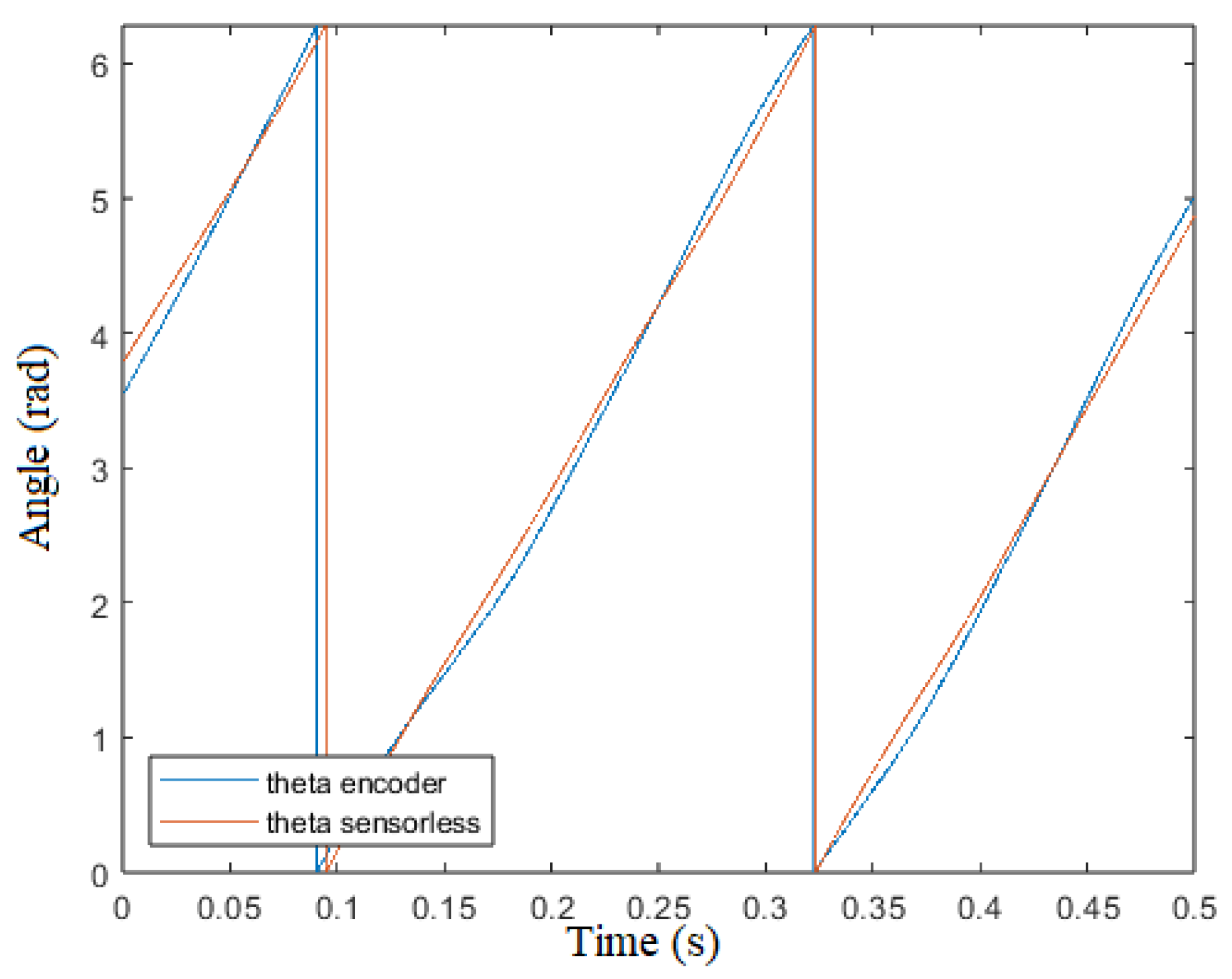
Figure 18.
Measured vs ()
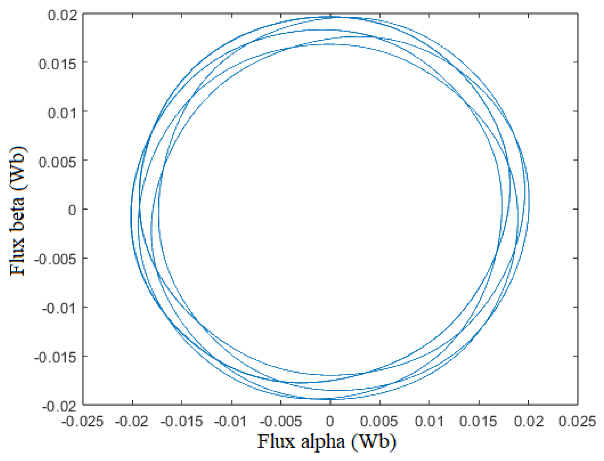
Figure 19.
Measured vs ()
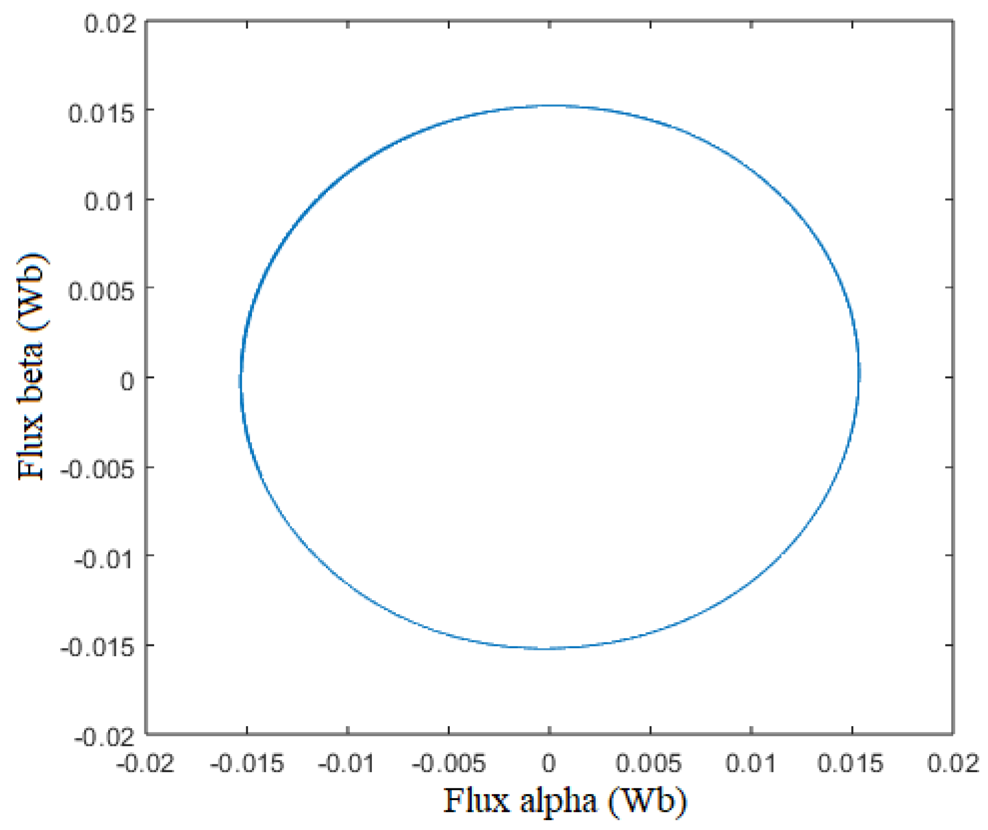
Figure 20.
error vs time ()
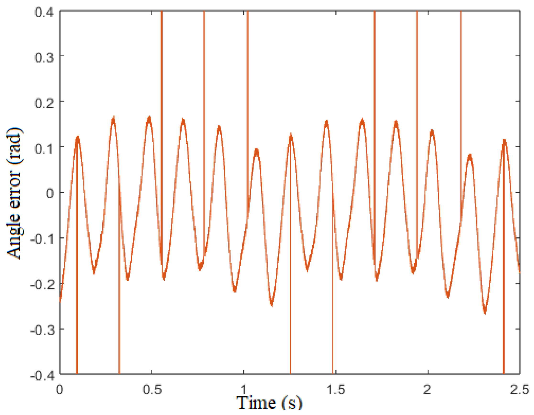
Figure 21.
error vs time ()
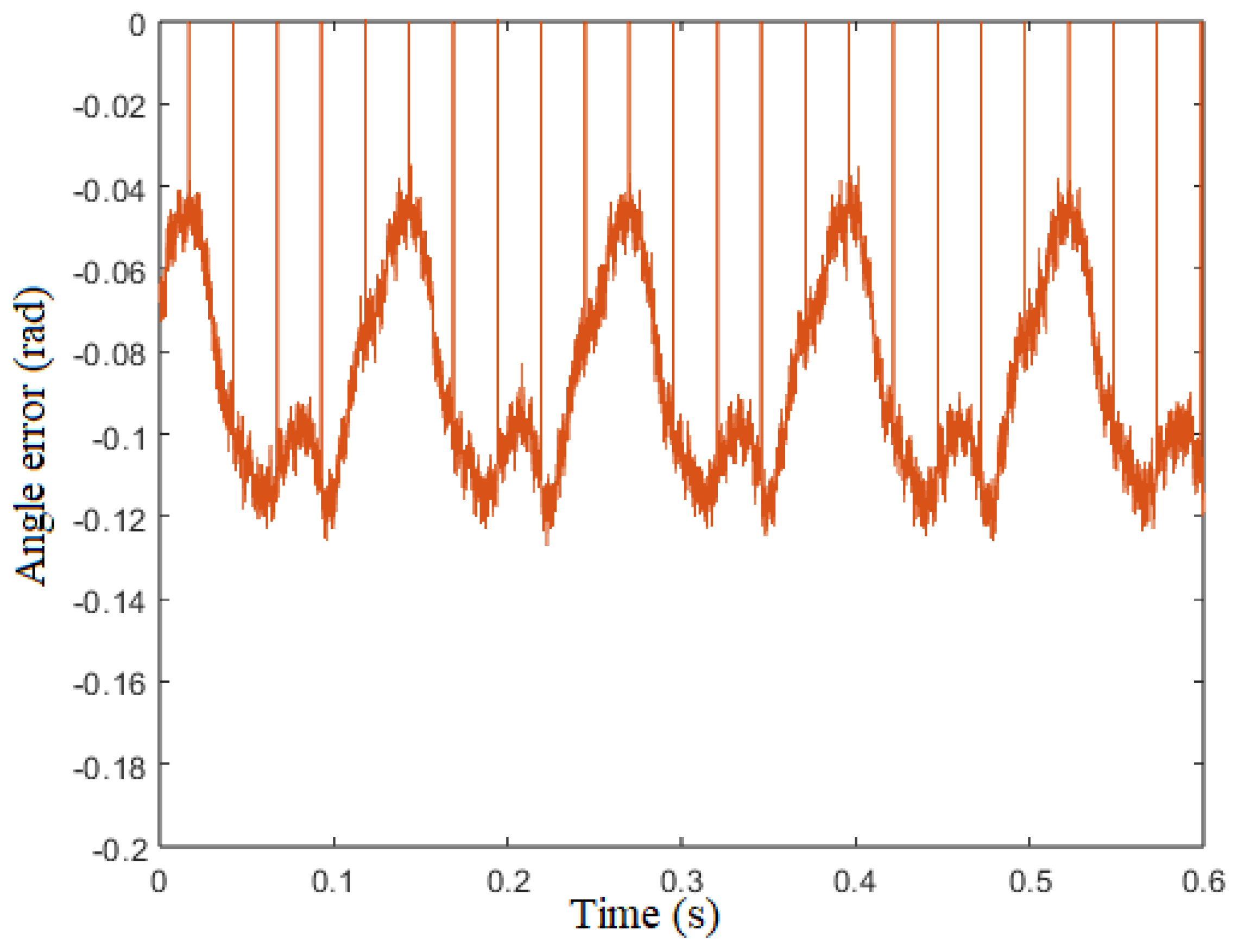
Figure 22.
Actual and estimated speed behaviour after a reference speed variation from 100 to 200 rad/s.
Figure 22.
Actual and estimated speed behaviour after a reference speed variation from 100 to 200 rad/s.
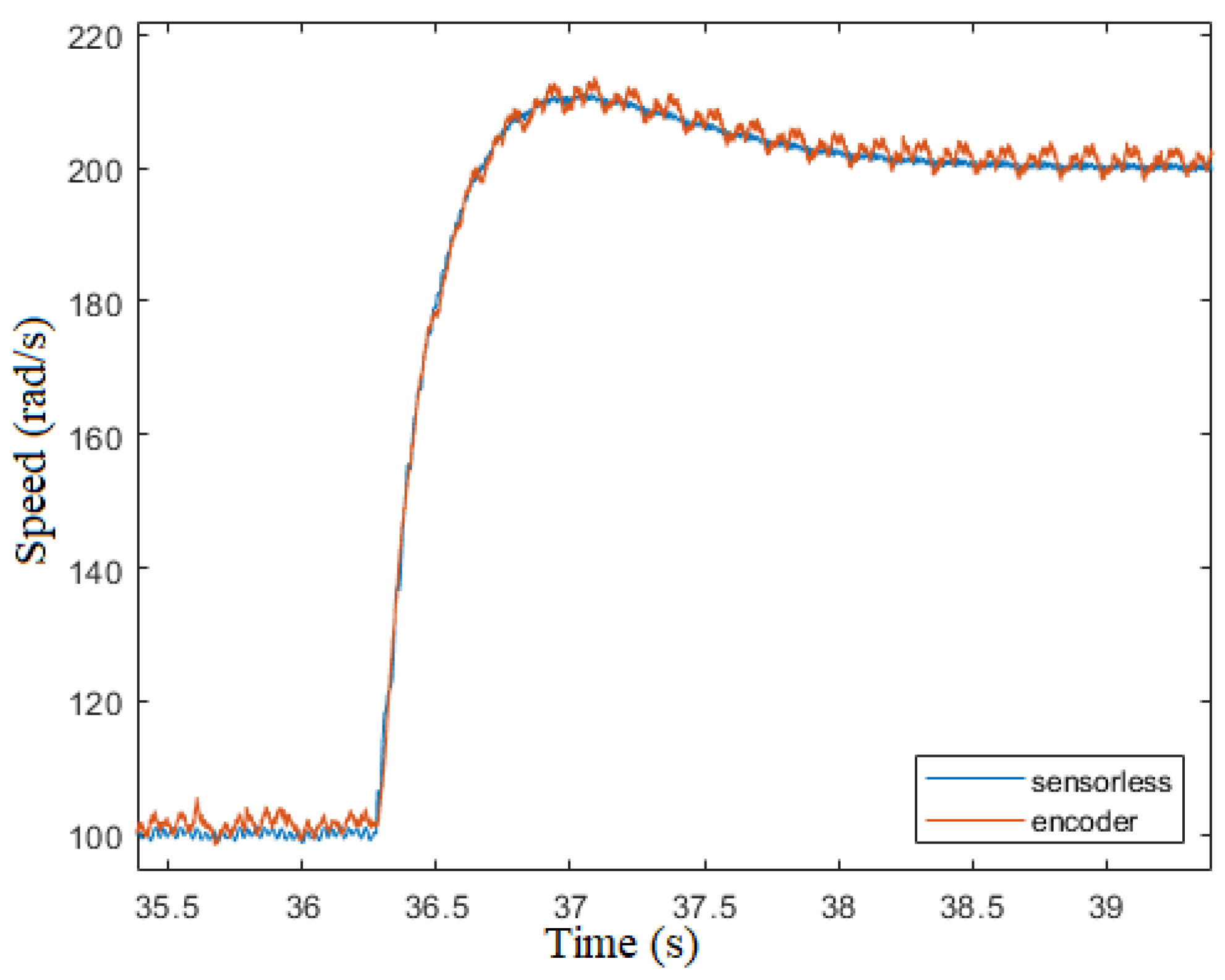
Figure 23.
Actual and estimated speed behaviour after a reference speed variation from 200 to 100 rad/s.
Figure 23.
Actual and estimated speed behaviour after a reference speed variation from 200 to 100 rad/s.
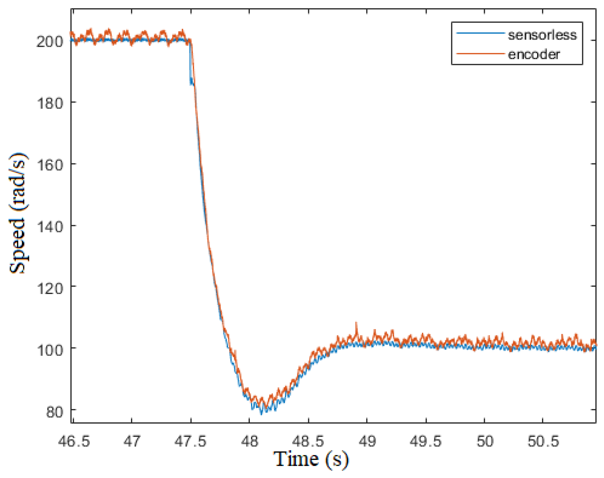
Figure 24.
Actual and estimated speed behaviour after a step load variation of +0.4Nm.
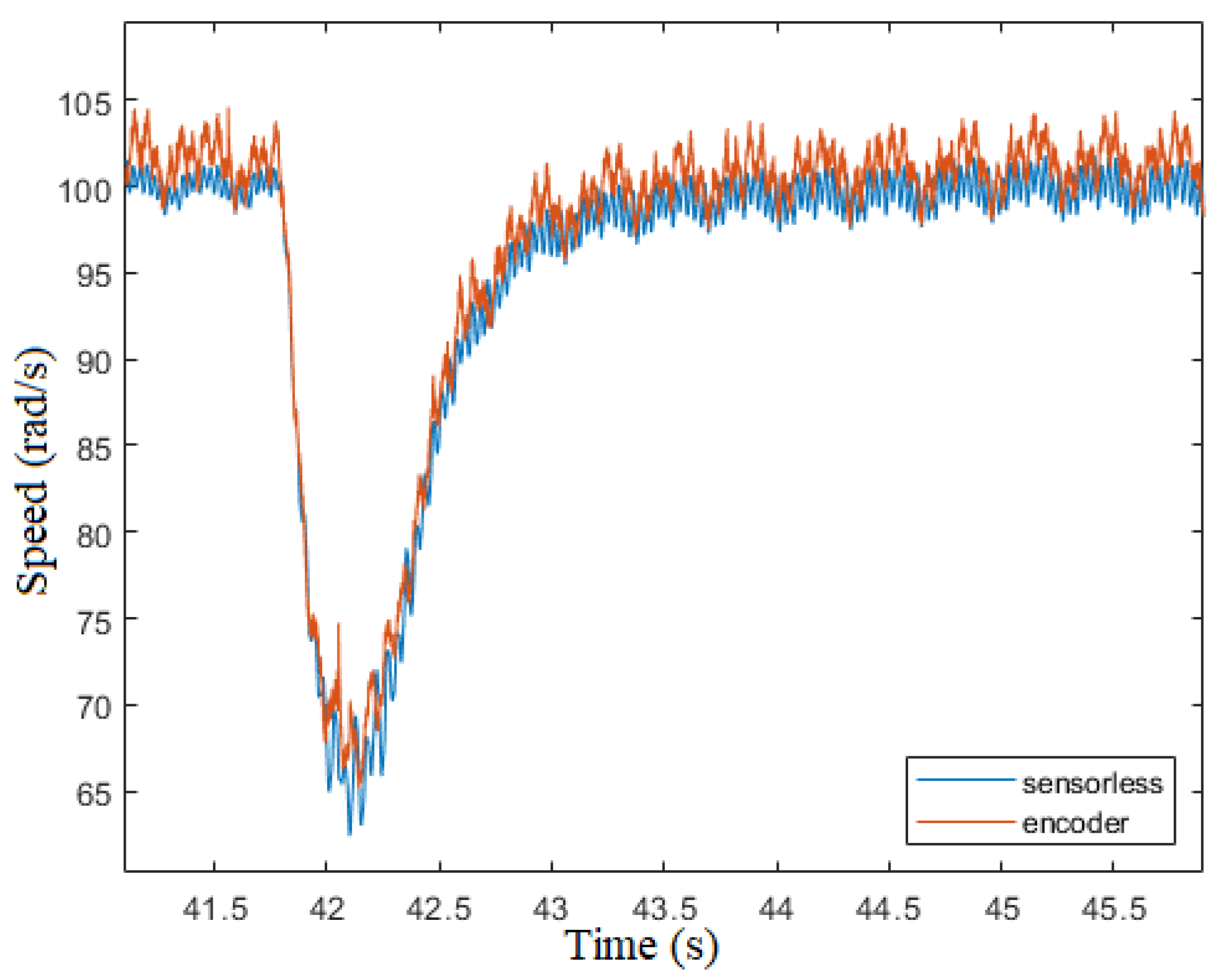
Figure 25.
Actual and estimated speed behaviour after a step load variation of -0.4Nm.
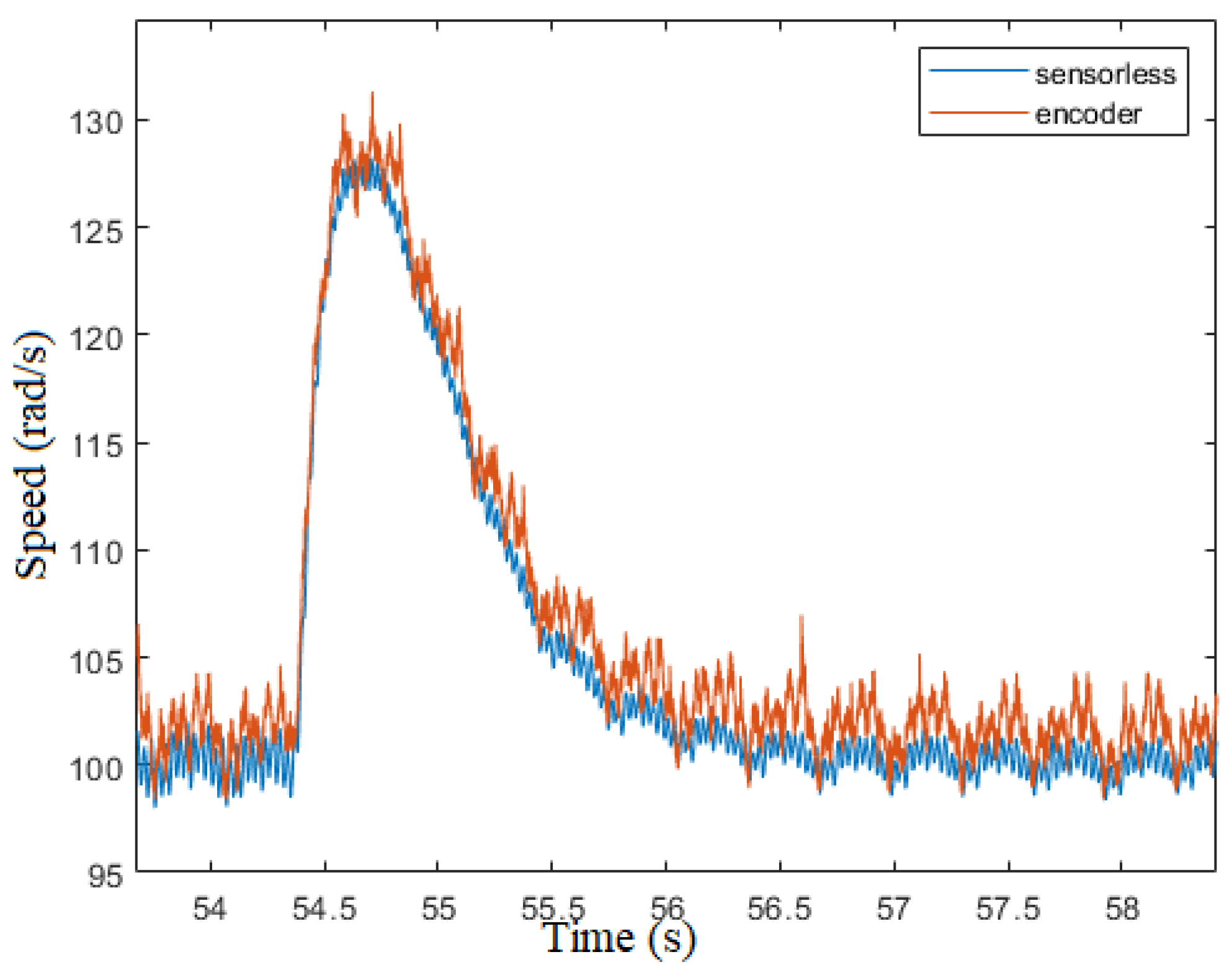

Table 1.
Motor Parameters
| Parameter | Symbol | Value | Unit |
|---|---|---|---|
| Pole number | 10 | - | |
| PM Flux linkage | 0.0144 | ||
| Winding resistance | 0.222 | ||
| Winding inductance | 0.25 | ||
| Nominal speed | 2500 | ||
| Nominal torque | 2 |
Disclaimer/Publisher’s Note: The statements, opinions and data contained in all publications are solely those of the individual author(s) and contributor(s) and not of MDPI and/or the editor(s). MDPI and/or the editor(s) disclaim responsibility for any injury to people or property resulting from any ideas, methods, instructions or products referred to in the content. |
© 2024 by the authors. Licensee MDPI, Basel, Switzerland. This article is an open access article distributed under the terms and conditions of the Creative Commons Attribution (CC BY) license (http://creativecommons.org/licenses/by/4.0/).
Copyright: This open access article is published under a Creative Commons CC BY 4.0 license, which permit the free download, distribution, and reuse, provided that the author and preprint are cited in any reuse.