Submitted:
11 October 2024
Posted:
14 October 2024
You are already at the latest version
Abstract
This study introduces an integrated methodology that incorporates vessel motion dynamics into the evaluation of operations and maintenance (O&M) costs for floating offshore wind turbines (FOWTs). By combining UWiSE, a discrete-event simulation tool, with SafeTrans, a voyage simulation software, the methodology accounts for vessel motion effects during offshore operations. The approach was demonstrated through a numerical case study at two wind farm sites, Marram Wind and Celtic Sea C, with a fictive wind farm layout of 100 × 15 MW NREL turbine on a UMaine VolturnUS-S platform. Three Major Component Replacement (MCR) strategies were assessed: Tow-to-Port (T2P), Floating-to-Floating (FTF), and Self-Hoisting Crane (SHC). The T2P strategy resulted in the highest O&M costs—94 k€/MW/year at Marram Wind and 97 k€/MW/year at Celtic Sea C—due to extended MCR durations (90-180 days), leading to lower availability (90%-94%). In contrast, the FTF and SHC strategies, which are still under development, demonstrate significantly lower costs and reduced downtime. The SHC strategy, in particular, has proven to be the most cost-effective, achieving up to a 64% reduction in costs while increasing availability to 97%-98%. The integrated approach incorporates vessel dynamics, accounting for factors such as wave direction, wave period, and vessel response to varying sea states. This allows for greater flexibility in setting operational limits, potentially permitting higher limits in favorable conditions where vessel motion impact is reduced. However, in scenarios where dynamic vessel responses lead to increased motions—such as when waves approach from the side or when the wave period is close to the vessel's natural roll period—more restrictive limits may be necessary, even if significant wave heights are lower. This flexibility or restriction highlights the importance of incorporating motion-based dynamics for emerging technologies in the evolving FOWT O&M market.
Keywords:
floating wind farms
; O&M modelling
; major component replacements
1. Introduction
The European Union (EU) is committed to reducing its greenhouse gas emissions by 55% from 1990 levels by the year 2030 [1]. This reduction is a crucial step towards achieving climate neutrality by 2050, aiming for an economy with net-zero greenhouse gas emissions. Renewable energy, especially wind power, will be essential for reaching this goal. Offshore wind is expected to generate between 7-11% of the EU’s electricity demand by 2030, utilizing just a fraction of the potential available in European waters [2].
To further capitalize on the vast potential of offshore wind, research and testing on floating offshore wind turbines (FOWT) are rapidly advancing. This technology has the potential to access 80% of the world’s offshore wind resources, which are located in waters deeper than 50 meters [3]. By 2040, FOWT are estimated to contribute up to 70 GW of wind capacity [4]. For FOWT to achieve the same success and cost reduction as Bottom-fixed wind turbines (BFWT), effective resource management is crucial from the beginning, ensuring both cost efficiency and high standards. A significant aspect of managing this resource is the operational phase, which poses substantial challenges due to the limited experience gained in performing operations and the readiness of the technologies used in the operational phase of FOWT systems. Currently, operations and maintenance (O&M) for FOWT is estimated to account for up to 30% of the Levelized Cost of Electricity (LCOE) [5]. Therefore, reducing these O&M costs is essential, making it a key area of cost reduction for FOWT to compete effectively in the same market as BFWT.
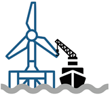
Based on pilot and demonstration-scale floating wind farm studies [6], significant costs in the O&M for FOWTs are associated with major component replacement (MCR) operations. MCR is performed using a tow-to-port (T2P) approach, where the turbine is disconnected from the Inter-array cables (IACs) and mooring lines (MLs), towed to a port facility for maintenance, and then towed back to the wind farm for re-connection [5]. On-site repairs for FOWT are actively being researched, and these will likely require specialized heavy-lift vessels (HLVs) equipped with motion compensation systems or other innovative solutions capable of performing replacements on-site, thereby reducing O&M costs. Before implementing such solutions, feasibility studies based on simulations using decision support tools for O&M cost modeling are essential. A review by McMorland et al. [5] highlighted a critical gap in current modeling approaches applied to FOWT studies [7,8,9,10,11]. These models often rely on static parameters such as wind speed and significant wave height as limiting criteria but overlook the crucial effects of vessel/platform motion dynamics (illustrated in the Figure 1) when determining operational limits for O&M activities. FOWT O&M activities involve significant multi-body interactions during deep-water transit, towing operations, and on-site O&M, where static criteria alone are insufficient. The vessel/platform responses are influenced not only by wind speed and significant wave height but also by factors such as wind-sea and swell wave period, wave direction, vessel speed, and the inherent characteristics of the vessels or platforms, including geometry, displacement, and mass distribution. Moreno et al. [12] found that relying solely on static significant wave height limits can be either too conservative or too optimistic depending on wave heading and period, impacting floating wind farm O&M costs and availability predictions. This underscores the importance of incorporating dynamic factors, such as vessel/platform motion limits, into O&M models for FOWT. Motion limits, which define the maximum allowable movement of a vessel or platform under specific conditions before operations must be halted, are critical for accurately assessing the operability of maintenance activities. By integrating these dynamic parameters, O&M models can offer a more realistic and precise evaluation of when and how maintenance can be safely and effectively conducted [13]. This raises an important question about the adaptability of existing O&M models for FOWT: How can current O&M models be adapted for a more accurate evaluation of FOWT operations?
In this research, we propose a methodology for evaluating O&M costs for FOWT, utilizing two complementary models. The first model, UWiSE [14], simulates discrete event failures of wind turbine components, identifying when maintenance is necessary and thereby initiating the need for logistical action. The second model, SafeTrans [15], focuses on modeling logistic actions by accounting for dynamic motion parameters in addition to static weather parameters while modeling vessel motions and on-site repair activities, allowing for accurate calculation of operational durations. By combining these models, the proposed approach offers a comprehensive evaluation of operation durations, including weather delays, and thereby translates these factors into O&M costs and availability for FOWT.
The paper is organized as follows: Section 2 details the methodology employed in this study, including the integration of UWiSE and SafeTrans models to evaluate O&M costs and operational availability. The merits of the integrated methodology are demonstrated through case studies. Section 3 outlines the different MCR strategies that are studied, specifying the setup of the case study, including the characteristics of the selected wind farm sites, the weather data utilized, failure rates, and the particulars of the vessels and technicians involved. Section 4 presents the results of the simulations, offering a benchmark analysis using the T2P strategy and comparing the effectiveness of different MCR strategies on costs and availability. Finally, Section 5 concludes the paper by summarizing the key findings, discussing the implications for future research in Section 6.
2. Methodology
The proposed methodology, illustrated by the flowchart in Figure 2, outlines the models, input space, and output space applied to O&M cost modeling for floating wind farms.
The UWiSE O&M Planner [14], developed by TNO, uses a time-sequential (discrete-event) simulation technique to model maintenance operations in an offshore wind farm over multiple years of its operational lifetime. This model integrates both controllable and uncontrollable input variables to analyze expected maintenance costs during the OPEX (operational expenditure) phase. Controllable variables include factors such as electricity prices, wind farm layout, expected component failure rates, day rates, replacement costs, and necessary maintenance actions. In contrast, uncontrollable variables are operational weather limits based on historical weather data.
UWiSE O&M Planner introduces variability in the inputs and outputs using the Monte Carlo technique. In this approach, (pseudo) random samples generate failure events based on component failure rates, triggering O&M actions. When a failure event is triggered, the met-ocean weather database is consulted to determine if the O&M actions can be carried out within predefined weather limits. If the random sample indicates wind and wave conditions exceeding the user-specified weather limits, the O&M action is delayed until conditions improve. This delay is used to evaluate the total duration of the O&M action within the UWiSE O&M Planner. However, this estimation does not account for vessel motion limits during O&M activities, which can be particularly crucial for FOWT operations.
To address this, MARIN’s software packages SEACAL and SafeTrans v10 [15] are integrated into the methodology. SEACAL, a 3D diffraction code based on linear potential flow theory and zero speed Green functions, calculates the hydrodynamic coefficients and the vessel responses in waves, accounting for viscous damping and incorporating forward speed corrections as necessary. SafeTrans is a voyage simulation software that accounts for the ship motion responses based on the seakeeping results from SEACAL, local weather conditions, operational criteria, bollard pull, resistance curves of the vessel, and wind and coefficients for wind-added resistance. SafeTrans is used to determine voyage duration, including potential delays due to adverse weather.
SEACAL is specifically applied to calculate the motion responses of vessels, generating response amplitude operators (RAOs). These RAOs are then input into SafeTrans, where they are used to compute the responses in irregular waves at the encountered weather conditions in a given route or location. The ship responses and weather conditions are then evaluated against user-specified criteria, resulting in delays if exceeded. By integrating motion-based operational criteria, this approach provides a more realistic assessment than the weather-based criteria alone used in UWiSE. The delays calculated by SafeTrans are then fed back into UWiSE as a correction step to refine the estimation of the duration of the O&M activity and ultimately the O&M costs. For the purpose of this study, the correction step is applied only to the O&M operations involving major component replacements, as they are regarded as the most sensitive operations affected by motion responses.
3. Case Study
To demonstrate the proposed methodology, this case study will evaluate different O&M strategies for FOWT using the inputs detailed in this section. It is important to highlight that the input values are derived from publicly available data and contributions from project partners. As these inputs are subject to change, any variations will inevitably lead to different outcomes. Consequently, such changes must be carefully considered when interpreting the results presented in the following sections.
Several aspects of real offshore wind farms are excluded from this study: The study focuses exclusively on offshore operations, excluding in-port operations and port logistics. The study excludes specific farm layouts, wake effects, electrical losses, and other losses not related to turbine failures and maintenance. Moreover, O&M activities on substations and the balance of plant are not considered. Spare parts storage and vessel unavailability are not accounted for to simplify the simulations.
3.1. Wind Farm Sites
For the case study, two wind farm sites are selected: MarramWind in the North Sea and Celtic Sea C in the Celtic Sea (see Table 1). The water depths at these locations range from 87 to 117.5 meters at MarramWind and 90 to 100 meters at Celtic Sea C. The ports of Fraserburgh (97 km away) and Loughbeg (130 km away) are considered as the operational ports for the simulations. The operational lifetime for the simulations is set to 25 years. Each site will feature a fictive, yet realistic scenario of 100 floating wind turbines.
3.2. Reference FOWT
The simulations consider a generic 15 MW NREL turbine [18] supported on a UMaine VolturnUS-S platform [19]. The floaters are moored using individual three-line non-redundant mooring systems and are connected to the grid via a submerged dynamic inter-array cable (IAC). The hub height is set at 150 meters above the waterline.
3.3. Weather Data
The weather dataset used in this case study consists of time-series hindcast metocean data with an hourly resolution from January 1, 1995, to December 30, 2012, covering in total 18 years. The key variables analyzed are mean wind speed () at 10 meters height in meters per second (m/s) and significant wave height () in meters (m), representing the height of combined wind waves and swell. Figure 3 plots the time series of and for Marram Wind and Celtic Sea C, displaying the raw data in lighter shades and the moving averages, calculated with a bin size of 1000, in darker lines. A comparison of and between these two sites shows that while wind conditions are similar, the wave height at Celtic Sea C is higher, particularly during the winter period. This is due to Celtic Sea C’s exposure to the Atlantic Ocean, whereas Marram Wind benefits from the shelter provided by Great Britain.
3.4. Failures Rates
Given the early stage of development for FOWTs, there is limited research and data available to establish reliable failure rates. Consequently, failure data for the next generation of 15 MW FOWTs has been estimated based on existing literature [16] and in-house expert knowledge. Maintenance-related failures have been categorized into three types: minor repair (mR), major repair (MR), and major component replacement (MCR). Additionally, annual maintenance, known as an annual campaign (AC), is required for each turbine and its floating platform.
Each failure category has a distinct average annual failure rate and requires different numbers of technicians and types of vessels. The repair times, costs, and necessary resources for each type of maintenance are detailed in Table 2. Maintenance tasks are assumed to proceed using the specified resources, with inputs derived from public sources and stakeholder consultation [28]. For MCR, the costs include the price of the new component along with other overhead expenses, whereas for MR and mR, only overhead costs are considered. Vessel and technician costs are not included in these figures but are accounted for separately. The repair or replacement process continues until the total required repair time is achieved, after which the turbine is restored to operational status.
It is important to note that the data in Table 2, including the necessary resources, is based on the tow-to-port (T2P) strategy, which is the current strategy employed for MCR for turbine-related components. Based on the discussion with the project partners, the floater-related components undergo maintenance, including MCR, on site, thus eliminating the need for the towing operation. For the turbine-related MCR activities, the resources and procedures are foreseen to change for the floating-to-floating (FTF) and self-hoisting crane (SHC) strategies, which will be discussed in detail subsequently. For the FTF and SHC strategies, an additional 20% is added to the MCR duration to account for the operational challenges associated with performing repairs on-site. The data for mR, MR, and AC are assumed to remain consistent across all simulations for all the strategies considered.
3.5. Vessels and Technicians
For the resources, various vessels are considered for maintenance activities, including Service Operation Vessels (SOVs), Anchor Handling Tug Supply vessels (AHTs), Crew Transfer Vessels (CTVs), Tug vessels, Semi-submersible Crane Vessels (SSCVs), onshore cranes, and self-hoisting cranes. The costs associated with these vessels encompass day and wait rates, as well as mobilization and demobilization costs, as detailed in Table 3. The towing operation for the FOWT was conducted with a reduced transit draft of 12 meters, as outlined in Appendix A. These cost inputs were derived from public sources and stakeholder consultation [28] and, while they may differ from current market rates, have been approximated to reflect the general range at the time of writing.
In addition to the costs, the vessels’ geometry, loading condition (including displacement, draft and inertia properties), resistance, and propulsion characteristics were modelled in SEACAL and Safetrans to compute the ship responses and sustained speed. Table 3 summarises the main particulars of the different vessels.
Furthermore, two technician groups, differentiated by shift periods, are assigned different rates in the simulations. Technician Group A operates on an 12-hour shift with a day/wait rate of €1200, while Technician Group B operates on a 24-hour shift with a day/wait rate of €2400. Activities that result in downtime are assigned to Technician Group B, where operations are performed in continuous shifts. For all other operations, Technician Group A is assigned, working in standard 12-hour shifts.
3.6. MCR Strategies
MCR operations are critical for FOWTs, especially when handling heavy lifts (50-400 tonnes) for MCR activities. These operations are the focus of this research. Currently, the T2P strategy is the approach for MCR in FOWTs. However, emerging strategies that enable on-site replacements without towing the turbine to port are in early development. These include the FTF strategy, which uses a crane vessel with relative motion compensation equipment, and the SHC strategy, which employs a crane system mounted directly on the FOWT structure.
In this section, the goal is to outline the strategies and their breakdown. These strategies involve several intermediate steps, each with specific durations, weather, and motion limits that will be considered for the simulations. It is acknowledged that the outlined strategies are not generic and are subject to change based on several factors, such as floater and turbine specifications, site-specific conditions, applied vessels and equipment and the O&M contractor. However, the outline provides the key steps involved in these strategies, enabling comparison between them. The breakdown of the T2P strategy steps was derived from public sources and stakeholder consultation [28], including wind farm owners, O&M operators, vessel contractors, and in-house experts. Furthermore, discussions with the vessel manufacturers and the SHC technology manufacturer have led to drawing the outline for MCR using the FTF and SHC strategies, which are shown in the tables below.
-
Tow-to-port (T2P) strategy: The T2P strategy is where major turbine components are replaced at an onshore O&M port facility. This strategy involves several key steps: disconnecting the FOWT from its mooring lines (MLs) and inter-array cables (IACs), towing it to port using a lead tug and an assisting tug vessel, performing necessary replacements at the port with an onshore crane, and finally towing the FOWT back to the offshore site for re-connection. During disconnection, the MLs and IACs are safely stored at a designated buoy near the offshore site. This ensures that they remain secure and accessible for reconnection upon the FOWT’s return. It is crucial that the IACs are properly sealed to prevent water ingress, which could otherwise lead to damage or failure of the electrical connections. Table 4 provides a detailed breakdown of the T2P strategy steps.The execution of the T2P strategy requires adherence to specific operational limits, which are defined by both weather and motion constraints. The weather limits primarily involve significant wave height () and wind speed (). Motion limits are categorized into two criteria: General Criteria at the vessel’s Center of Gravity (CoG) [C1] during vessel transit, and Towing Criteria at the wind turbine’s nacelle [C2] when the FOWT is being towed.The general criteria at the vessel’s CoG involve surge acceleration (), sway acceleration (), and heave acceleration () motions, which correspond to linear accelerations along the longitudinal, lateral, and vertical axes, respectively (see Figure 1). Additionally, roll motion (), which refers to the rotational movement around the longitudinal axis, is also considered under these criteria. These parameters are critical during a typical transit operation for a vessel because they directly affect the comfort and safety onboard. Excessive acceleration values and roll motion can lead to a loss of postural stability and seasickness, posing significant risks to the technicians onboard and reducing their ability to work. These criteria correspond to the operational criteria for tug operations defined within the SafeTug JIP [21]. The operational criteria from the SafeTug JIP are in-line with the criteria for “Light Manual work” from Nordfosk [22] and for CTV operations given by the Carbon Trust [23].The towing criteria are applied to the nacelle of the wind turbine to monitor accelerations during towing operations. Located at the top of the wind turbine tower, the nacelle represents a significant source of mass and inertia, making it a critical point for evaluating motion-induced stresses. The criteria specifically monitor surge acceleration , sway acceleration , roll motion , and pitch motion . By focusing on the nacelle, these criteria help identify excessive movements that could result in structural damage.In Safetrans simulations, the motion criteria are applied to the assist tug during the transit phases, as it is the slowest vessel and will have the largest motions. During towing and offshore operations, the criteria are instead applied to the lead tug.
-
Floating to floating (FTF) strategy: An alternative for performing MCR directly onsite for FOWTs involves the use of a Semi-Submersible Crane Vessel (SSCV) equipped with a relative motion compensation system. Currently, such dedicated SSCVs for MCR are not available, but designs for these vessels and their motion compensation equipment are being proposed as cost-efficient solutions; see [23].In the present case study, a 120-meter, six-column SSCV is assumed (see Table 3). The SSCV maintains its position next to the FOWT using its Dynamic Positioning (DP) system, which compensates for the mean and low-frequency relative motions between the FOWT and the SSCV. Both the semi-submersible FOWT and the SSCV have favorable seakeeping characteristics that limit wave-frequency motions. It is assumed that any remaining wave-frequency motions will be compensated by an innovative, yet-to-be-developed motion compensation system in the crane. Such motion compensation systems have been proposed by [24,25]. Based on these designs, it is assumed that the motion compensation systems will be capable of compensating for the relative motions between the FOWT and the crane as per criteria [C3] in Table 5.Table 5 outlines the FTF strategy using SSCVs for MCR. This strategy includes key actions such as transiting the SSCV to the site with the new component and technicians, performing the MCR operation onsite using the onboard crane, and then transiting back to port with the removed component and technicians. The same motion criteria are applied to the SSCV as those for the tug vessels [C1]. Due to its favorable semi-submersible seakeeping characteristics, large size, and significant mass, these limits are reached in higher sea states. A higher weather limit is also applied to the SSCV compared to the tug vessels used in the T2P strategy.For the MCR by FTF, the relative motions between the RNA and the SSCV crane are critical. Surge (X), sway (Y), heave (Z) and roll () motions of both floaters cause relative movements of the lifted component, making it challenging to align and position the component accurately during replacement. To address these motions, the SSCV is expected to be equipped with a novel motion compensation system, which is currently non-existent. In this case study, it is assumed that the system will be capable of compensating for the relative motions between the RNA and the crane tip, as listed in [C3] in Table 5.
-
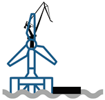
Self hoisting crane (SHC) strategy: Another alternative for performing MCR on-site involves using a Self-Hoisting Crane (SHC) system to carry out component replacements directly on the FOWT. This strategy utilizes a transportation platform and a crane that is integrated with the FOWT itself, as opposed to the FTF approach, where the crane operates from a separate vessel. By becoming part of the FOWT structure, the SHC system mitigates the relative motions between the FOWT and the components being lifted. Examples of SHC systems can be found in [26] and [27], although specific operational details and limits are still under development and not fully established.Table 6 outlines the SHC strategy. In this approach, the SHC crane and replacement component are transported to the wind farm location. The platform, at its transit draft, is towed to the site by a small tug vessel. Upon arrival, the platform is ballasted to its operational draft and coupled to the FOWT foundation. A CTV assists in transferring personnel between the tug, FOWT, and the SHC platform. Once the platform is secured to the FOWT, the SHC is hoisted onto the wind turbine tower, providing stability during MCR operations. The SHC crane is secured to the platform using winches to ensure stability during the maintenance tasks.Motion limits are calculated at the SHC platform, where the maintenance components are stored. Due to the ongoing development of the SHC approach and the lack of specific operational limits, only a heave (Z) limit of 0.4 meters RMS is applied [C4]. This criterion assumes the use of an Active Heave Compensation (AHC) system to lift components from the platform deck. Additionally, it is assumed that the SHC approach will include a horizontal guidance system during lifting to prevent swinging motions and interference with the FOWT structure. The calculation of the vertical motion at the SHC platform is based on the RAOs of the FOWT as it was assumed that the platform would be coupled to the FOWT. Since little details are known about the platform and coupling characteristics, it was assumed that the platform did not have an impact on the FOWT motions.
4. Results and Discussion
In this section, the different O&M strategies based on the inputs discussed in Section 3 will be evaluated using two key performance indicators (KPIs):
-
KPI I: Maintenance and Downtime Cost (MDC) [k€/MW/year]MDC quantifies the O&M costs and revenue losses due to downtime, normalized to the turbine’s capacity and expressed on a per-year basis. By integrating these factors, MDC provides a comprehensive view of the financial impact of maintenance activities on wind farm operations. It is calculated as:where is the cost of vessels, is the cost of technicians, is the cost of spare parts, and represents revenue loss due to downtime, with i indicating each O&M action. n is the total number of O&M actions, MW represents the wind farm’s total capacity in megawatts, and year denotes the operational period of the wind farm in years.
-
KPI II: Time-based Availability () [%]Time-based availability measures the percentage of time a wind farm is operational compared to the total time, calculated in hours. This KPI is essential for assessing the efficiency of the wind farm. It is calculated as:where is the actual operational time, and is the total possible operational time. A higher value indicates that the O&M strategy effectively minimizes downtime and maximizes energy production.
It is important to note that the KPIs defined here may differ from those used in other studies, where the MDC might also include additional expenses such as insurance costs, harbor fees, etc., which are not considered in our analysis.
4.1. Benchmarking Using the T2P Strategy
The T2P strategy for MCR activities in FOWTs is currently the conventional approach and serves as a baseline for benchmarking against the emerging FTF and SHC strategies, which are still in early development stages.
Figure 4 illustrates two KPIs for the FOWT sites at Marram Wind and Celtic Sea C: MDC and . The MDC, expressed in k€/MW/year, comprises the total O&M costs and revenue losses, deliberately shown as distinct bars for easier interpretation. The stacked bars represent the various O&M cost categories, including WTG major and minor repairs, major component replacements, floating substructure maintenance, and scheduled maintenance, while the orange bar shows the associated revenue losses accounting for these O&M activities. Error bars are used to depict the variability derived from 100 simulation samples, each starting on a random date to account for different historical weather conditions (as detailed in Figure 3). This variability captures the uncertainty inherent in cost and availability estimates due to fluctuating metocean conditions, which significantly impact these KPIs.
The results indicate that the average O&M costs for Marram Wind and Celtic Sea C are approximately 94 k€/MW/year and 97 k€/MW/year, respectively. Although a direct comparison of these estimates should be treated with caution due to the differing assumptions underlying the model inputs, they are consistent with the limited available data [20,23]. This consistency supports the validity of both the inputs and the methodology used. Notably, Celtic Sea C shows higher MDC costs, mainly due to revenue losses, which correspond with a 4% lower . This difference is likely due to different metocean conditions between the two sites, as illustrated in Figure 3. While is relatively consistent across both sites, is significantly higher at Celtic Sea C, resulting in increased wave-induced restrictions on O&M activities. These conditions are expected to lead to additional weather delays, extended downtime, and greater revenue losses. Furthermore, the longer distance to port for Celtic Sea C (approximately 130 km, compared to 100 km for Marram Wind; see Table 1) increases transit times, resource usage, and delays, contributing to higher MDC and revenue losses. This difference is also reflected in the values, with Celtic Sea C at 90% compared to 94% at Marram Wind, indicating more frequent and longer downtimes at Celtic Sea C.
At both sites, MCR activities constitute the largest cost component within MDC, accounting for approximately 45–50% of total O&M costs, including uncertainties. This underscores the significant role of MCR in the O&M strategy for FOWTs.
4.2. Comparison of MCR Strategies
In this section, the three MCR strategies outlined earlier will be compared, specifically evaluating MDC for MCR activities. For this comparison, MDC will account only for the costs associated with MCR activities and the corresponding revenue losses resulting from activity downtime. For the calculations, other O&M activities, such as major repairs (MR), minor repairs (mR), and annual campaigns (AC), are assumed to remain consistent across all three strategies for the simulations, ensuring that any differences in are attributable only to the variations in the MCR strategies.
Figure 5 presents the normalized MDC for three different MCR strategies (T2P, FTF, SHC) at two wind farm sites: Marram Wind and Celtic Sea C. The MDC for each strategy is normalized against the T2P strategy to provide a clear comparison of relative costs. The stacked bar plots show the breakdown of costs into vessels, technicians, spare parts, and revenue losses. Error bars represent the uncertainty range, highlighting the variability in MDC over the analyzed weather uncertainty.
At Marram Wind, the T2P strategy exhibits the highest normalized MDC, serving as the baseline with a value of 1.0. The FTF strategy shows a notable reduction in normalized MDC to approximately 0.42, suggesting a 58% decrease in costs compared to the T2P strategy. The SHC strategy further reduces the normalized MDC to around 0.36, representing a 64% cost reduction relative to T2P. These cost reductions are accompanied by improvements in availability (), increasing from 94% for T2P to 98% for FTF, and 97% for SHC.
At Celtic Sea C, the T2P strategy again shows the highest normalized MDC, and is set at 1.0. The FTF strategy reduces the normalized MDC to about 0.53, indicating a 47% reduction in costs. The SHC strategy achieves a further reduction, with a normalized MDC around 0.45, corresponding to a 55% decrease in costs relative to the T2P strategy. The at Celtic Sea C improves significantly from 90% for T2P to 97% for both F2F and SHC, reflecting enhanced operational performance with these alternative strategies.
The duration of MCR operations significantly impacts the MDC linked to MCR. Figure 6 shows box plots of MCR durations for each strategy (T2P, FTF, SHC) across different months at two sites: Marram Wind and Celtic Sea C. These durations are averaged for seven turbine-related MCR activities, aggregated by month, and compared using UWiSE (weather limits) and SafeTrans (motion limits), offering a comparative view of how different months and years affect MCR durations. Notably, certain MCRs, like those involving blades, have significantly longer repair times compared to components such as yaw or pitch systems (see Table 2). The plots are based on simulations over 18 years using hindcast data, highlighting the variability and uncertainty in MCR duration estimates. The box plots show the median (central line), interquartile range (IQR, 25th-75th percentiles), and outliers, providing a clear view of MCR duration distributions. The whiskers indicate typical duration ranges, extending to the minimum and maximum values within 1.5 times the IQR. The aim is to demonstrate the variability of MCR durations across months.
The box plots in Figure 6 show that the T2P strategy results in the longest MCR durations, with median values often ranging between 90 and 180 days at both sites, particularly during the winter months (September to February). This indicates that the T2P operation is typically feasible only during the summer months (May to August). For example, if the operation is initiated in January, there is about a 120-day delay (4 months); in February, the delay is approximately 90 days (3 months); in March, about 60 days (2 months); and in April, around 30 days (1 month), culminating in May when the T2P MCR operation can be performed. During the summer months, the median MCR duration for T2P is about 30 days, with variations up to 60 days, particularly for the Celtic Sea C site, where higher wave heights are more common. For the SHC strategy, the median MCR durations are generally shorter, remaining below 10 days during the summer months and extending slightly over 30 days during the winter at both sites. The FTF strategy demonstrates the shortest MCR durations, with median values around 10 days and annual variations below 30 days across all months at both wind farm sites, showcasing the year-round effectiveness of this strategy.
The shorter MCR durations for the FTF strategy can be attributed to the higher transit speed of the SSCV vessel (see Table 3) and its favorable seakeeping characteristics, both during transit and operations (see Table 5). These factors minimize downtime and reduce added durations, allowing the vessel to operate in sea states with up to 4.5 m during transit and 3.5 m during the MCR operation onsite, assuming that motion compensation systems in the crane can mitigate relative motions as specified by criteria [C3].
However, despite the shorter durations, the FTF strategy’s higher vessel leasing costs (see Table 3) result in approximately a 10% increase in MDC for MCR compared to the SHC strategy. Additionally, the reduced MCR durations for the FTF strategy also lead to lower technician costs, as shown in Figure 5, due to the reduced amount of working time required. This suggests that the MDC for MCR using the FTF strategy would be lower than the SHC in winter months, as the SHC—despite offering lower resource leasing costs—may be more susceptible to weather delays that the FTF strategy can withstand.
Figure 6 compares MCR durations derived from SafeTrans (orange boxes) and UWiSE (blue boxes). Overall, there is a good match between the two tools for MCR durations. This general agreement shows that the motion limits applied in SafeTrans closely align with the weather limits used in UWiSE. However, the comparison also reveals that SafeTrans sometimes calculates either longer or shorter MCR durations than UWiSE.
A key difference between the two tools lies in how they handle weather delays during the evaluation of MCR operations. To illustrate this, the "Tow WT to Port" step within the T2P strategy was modeled using various weather conditions based on different start dates from the hindcast weather data for both UWiSE and SafeTrans. The scatter plot shown in Figure 7 highlights the differences by comparing the allowable significant wave height () limits determined by UWiSE (weather limits) and SafeTrans (motion limits).
The plot reveals that, for certain samples, SafeTrans permits limits to exceed 3m, whereas UWiSE consistently keeps the below this threshold. This divergence occurs because SafeTrans accounts for the vessel’s dynamic responses to varying wave conditions, such as wave direction and period, thereby offering more flexibility in operational limits under specific sea states. For instance, in scenarios where waves are head-on or the wave period is short, SafeTrans allows higher values due to the reduced impact on vessel motions. These higher values are evident in data points exceeding 3m on the scatter plot.
However, there are instances where SafeTrans can be more restrictive than UWiSE. This occurs when the dynamic vessel responses lead to greater motions, making it unsafe to proceed with operations, even if the values are lower. For example, if the waves are approaching from the side (beam seas) and the wave period is close to the natural roll period of the ship, SafeTrans would be more restrictive due to increased roll, which will lead to higher acceleration values. In such cases, SafeTrans would impose stricter limits on operations compared to UWiSE, which applies a constant limit that does not account for wave period and wave direction. As a result, UWiSE might allow operations in conditions where motion criteria would actually be exceeded.
In conclusion, accounting for motion limits enables dynamic parameter setting during analysis, which is crucial for emerging technologies in the FOWT market. This approach provides more accurate and adaptable limits for specific sea states and vessel responses, ensuring safer and more effective assessments in complex marine conditions.
5. Conclusions
This study presents a comprehensive methodology for evaluating the operations and maintenance (O&M) costs associated with floating offshore wind turbines (FOWTs). By integrating motion-based operational criteria using SafeTrans, a voyage simulation software, with UWiSE, a time-sequential (discrete-event) simulation tool, this methodology allows for a more realistic assessment of maintenance activities over an offshore wind farm’s operational lifetime. This approach addresses a significant gap in existing modeling practices, which often rely on static parameters like wind speed and wave height but fail to account for the complex motion dynamics of vessels and platforms essential in FOWT operations.
To demonstrate the proposed methodology, this study evaluated two wind farm sites: Marram Wind in the North Sea and Celtic Sea C in the Celtic Sea. These sites were chosen to incorporate three distinct MCR (major component replacement) strategies—Tow-to-Port (T2P), Floating-to-Floating (FTF), and Self-Hoisting Crane (SHC). The simulations used a generic 15 MW NREL turbine supported on a UMaine VolturnUS-S platform in a fictive wind farm layout of 100 turbines. The weather dataset consisted of an 18-year time-series of hindcast metocean data to account for weather uncertainties, providing a robust foundation for simulating realistic operational conditions. Failure data for the next generation of 15 MW FOWTs were estimated from existing literature and expert knowledge and categorized into four types of maintenance actions: minor repairs (mR), major repairs (MR), major component replacements (MCR), and annual campaigns (AC). Different resources, including vessels and technicians, with their specific characteristics, were considered to simulate these maintenance actions accurately.
The T2P strategy was used as the benchmark in this study because it is the most widely adopted method for MCR operations, until now. This strategy involves towing the turbine to a port for maintenance, then returning it to the wind farm. The results revealed that MCR operations under the T2P strategy incur the highest Maintenance and Downtime Costs (MDC), with average O&M costs of approximately 94 k€/MW/year for Marram Wind and 97 k€/MW/year for Celtic Sea C. The extended MCR durations, ranging from 90 to 180 days, significantly contribute to these high costs. This is due to longer transit times, increased wave-induced restrictions, and the dependency on suitable weather windows for safe towing and re-connection. Consequently, the T2P strategy results in lower time-based availability, with Marram Wind achieving 90% availability and Celtic Sea C achieving 94%.The lower availability and higher costs at Celtic Sea C are primarily due to its more challenging metocean conditions and the longer distance to port, which increase transit times and delays.
In contrast, the FTF and SHC strategies were more effective in reducing both the MDC and operational durations. The SHC strategy emerged as the most cost-effective, with median MCR durations generally below 10 days during summer and slightly over 30 days in more challenging conditions. The FTF strategy showed MCR durations with median values around 10 days and an annual spread below 30 days across all months. The shorter durations for the FTF strategy can be attributed to the higher transit speed and favorable seakeeping characteristics of the semi-submersible vessel used in the operations. However, the cost of leasing this specialized vessel is reflected in slightly higher MDC compared to the SHC strategy. When normalizing MDC against the T2P strategy, both the FTF and SHC strategies showed approximately 50% lower costs, with the SHC strategy being the least expensive overall. Availability for both FTF and SHC strategies was significantly higher than T2P, maintaining levels between 97% and 98%.
The comparison between SafeTrans and UWiSE highlights the differences in how each tool handles operational limits during MCR activities. While UWiSE applies static weather limits, SafeTrans accounts for dynamic vessel motions, offering more flexibility in certain sea states. Depending on the scenario, either tool may yield longer or shorter MCR durations. SafeTrans can permit higher significant wave heights () in conditions with reduced motion impact, while in other cases, it may impose stricter limits due to increased vessel motions. This distinction is particularly important for FOWT operations, where the sensitivity of floating structures to metocean parameters requires careful consideration of both weather and motion limits, making the motion-based operability assessment more valuable, especially given the emerging technologies in the FOWT market.
It is important to note that the developed methodology for motion-based operability assessment has been demonstrated specifically for MCR operations at floating wind farms, as these limits are deemed critical for such activities. As the market evolves, these motion limits are expected to become well established for a broader range of operations, including preventive and annual maintenance campaigns. Incorporating a motion-based operability assessment into these operations would enhance the accuracy of O&M model estimations, leading to more efficient planning and safer execution of tasks across the FOWT sector.
6. Future Works
Building on these findings, several key areas warrant further exploration to enhance the discussions related to O&M cost modeling for FOWTs:
-
Incorporating Availability and Market Constraints: The current analysis assumes full vessel availability for all maintenance strategies, which simplifies the modeling process. However, in practice, the availability of specialized vessels (like SSCVs), is likely to be limited due to high demand in the offshore market. In contrast, self-hoisting cranes, along with their purpose-built platforms designed for specific FOWT types, are anticipated to have higher availability as they only require small supporting vessels for transportation. Similarly, the availability of critical spare parts may be constrained, leading to extended repair times. The scarcity of both vessels and spare parts can result in increased downtime and revenue losses, particularly as the floating offshore wind turbine (FOWT) market continues to grow.To provide a more accurate representation of real-world conditions, future research should incorporate constraints related to vessel and spare parts availability into O&M simulations. This could include modeling different scenarios, such as shortages and scheduling conflicts, to assess the economic and operational impacts more realistically. Such simulations would be particularly valuable in a competitive market, where resource availability is a critical factor in the success of offshore projects.Additionally, port logistics and quayside operations have been excluded from the current analysis. These logistical processes can significantly affect the overall maintenance timeline and costs, especially in congested or underdeveloped ports. By incorporating port logistics and quayside operations into future simulations, the full scope of potential bottlenecks in the O&M process can be captured, leading to a more comprehensive evaluation of the operational challenges in offshore wind farm maintenance.
- Quantifying Greenhouse Gas (GHG) Emissions: While this study focused on cost efficiency, the environmental impact, particularly in terms of fuel consumption and GHG emissions, is also crucial. Deep-water operations like T2P require more fuel, resulting in higher emissions. Future research should quantify GHG emissions for different O&M activities using comprehensive GHG assessment methods. This would provide a more holistic view of the sustainability of various maintenance actions.
- Enhanced Risk Assessment Models: The FOWT industry faces numerous risks, ranging from operational challenges to extreme weather events. Developing comprehensive risk assessment models that account for these variables will be critical for the long-term viability and safety of O&M operations. Future research could focus on creating robust risk models that integrate both financial and operational risks, including the potential impacts of severe weather conditions, which are expected to increase in frequency and intensity due to climate change. These enhanced models would enable operators to better prepare for and mitigate risks associated with extreme conditions, contributing to more resilient and reliable offshore wind operations.
By addressing these areas, future research can further refine the methodologies presented in this study, contributing to the development of more sustainable, economically viable, and environmentally responsible solutions for the maintenance of floating offshore wind turbines.
Author Contributions
VVD contributed to the conceptualization, methodology, formal analysis, writing of the original draft, and funding acquisition. LJH contributed to the methodology and formal analysis. JHM contributed to the methodology, formal analysis, review, and editing. JJS contributed to the methodology, editing, funding acquisition, and project administration.
Funding
The project has been carried out with a contribution of subsidy from the Dutch Ministry of Economic Affairs, National Schemes EZK-subsidies, TKI Offshore Energy (part of energy innovationNL), as taken care of by RVO (Netherlands Enterprise Agency). In addition, the GROW Common Fund has contributed financially to the project:
Institutional Review Board Statement
Not applicable.
Informed Consent Statement
Not applicable.
Data Availability Statement
The data used in this research is gathered from various sources, as detailed within the paper. Usage of data in the tools mentioned is subject to licensing agreements for the software. However, the authors encourage data sharing, and interested parties can obtain access by directly contacting the corresponding author.
Acknowledgments
The authors would like to express their sincere gratitude to the project partners —Ampelmann, Boskalis, Royal IHC, Seaway 7, Shell, Van Oord, Carbon Trust and Seatrium — for their invaluable support and timely inputs through discussions, which greatly contributed to the successful completion of this research. Special thanks are extended to Liftra for providing the necessary inputs for developing the Self-Hoisting Crane (SHC) strategy illustrated in this paper.
Conflicts of Interest
The authors declare no conflicts of interest. The funders had no role in the design of the study; in the collection, analyses, or interpretation of data; in the writing of the manuscript; or in the decision to publish the results.
Abbreviations
The following abbreviations are used in this manuscript:
| AC | Annual campaign |
| AHT | Anchor handling tug |
| AHTS | Anchor handling tug supply vessel |
| BFWT | Bottom-fixed wind turbines |
| C1 | General criteria at the vessel’s center of gravity |
| C2 | Towing criteria at the wind turbine’s nacelle |
| C3 | Floating to floating limits at nacelle |
| C4 | Self hoisting crane criteria at SHC platform deck |
| CoG | Center of gravity |
| CTV | Crew transfer vessels |
| D/W | Day/wait rate |
| FTF | Floating-to-floating |
| FOWT | Floating offshore wind turbine |
| HLV | Heavy-lift vessel |
| IAC | Inter-array cable |
| KPI | Key performance indicator |
| MCR | Major component replacement |
| MDC | Maintenance and downtime cost |
| ML | Mooring lines |
| MR | Major repair |
| mR | Minor repair |
| M/D | Mobilization/demobilization rate |
| MW | Megawatt |
| O&M | Operations and maintenance |
| OPEX | Operating expenses |
| RAO | Response amplitude operator |
| SOV | Service operation vessel |
| SSCV | Semi-submersible crane vessel |
| SHC | Self-hoisting crane |
| T2P | Tow-to-port |
| UWiSE | Unified windfarm simulation environment |
| Time-based availability | |
| Cost of vessels | |
| Cost of technicians | |
| Cost of spare parts | |
| Significant wave height | |
| Revenue loss due to downtime | |
| Length between perpendiculars | |
| Root Mean Square | |
| T | Draft |
| Bollard pull | |
| Actual operational time | |
| Total possible operational time | |
| Wind speed at 10 meters | |
| X | Surge |
| Y | Sway |
| Z | Heave |
| Displacement | |
| Roll | |
| Pitch |
Appendix A. Transit Draft of the FOWT
For the towing operation of the Floating Offshore Wind Turbine (FOWT), the draft was reduced from the in-place draft of 20 meters to a transit draft of 12 meters. This reduction in draft serves to lower the drag forces acting on the floater and consequently reduces the required bollard pull from the towing vessels. The applied weight distribution for the 15 MW FOWT at the transit draft of 12 meters is provided in Table A1.
The transit draft of 12 meters was chosen to maintain the stability of the FOWT, including the Rotor-Nacelle Assembly (RNA), while also avoiding shallow water effects on the top of the pontoons. These design considerations ensure that the FOWT remains stable and operational during the towing process, minimizing potential risks during transport.

Table A1.
FOWT Parameters at Transit Draft of 12m.
| FOWT Parameters at Transit Draft of 12m | ||||
|---|---|---|---|---|
| Designation | Value | |||
| Draft | 12 m | |||
| Displacement | 16,703 tonnes | |||
| Waterplane Area | 442.9 m 2 | |||
| Vertical Center of Gravity | 20.08 m | |||
| Transverse Metacentric Height | 14.10 m | |||
| Roll Radius of Gyration | 49.59 m | |||
| Pitch Radius of Gyration | 49.59 m | |||
| Yaw Radius of Gyration | 34.19 m | |||
The selected parameters ensure that the FOWT retains adequate stability during transit, with the metacentric height and radii of gyration indicating strong resistance to rolling, pitching, and yawing motions. This allows for a safe and efficient towing operation, while also ensuring that the FOWT remains robust against environmental forces during transport.
References
- Rodrigues, A. A. (2024). Fit for 55: The EU Plan for a Green Transition. Sustainable Finances and the Law: Between Public and Private Solutions (pp. 333-344). Cham: Springer Nature Switzerland.
- Fernández-Guillamón, A., Das, K., Cutululis, N. A., & Molina-García, Á. Offshore wind power integration into future power systems: Overview and trends. Journal of Marine Science and Engineering 2019, 7, 399. [Google Scholar] [CrossRef]
- Bento, N., & Fontes, M. Emergence of floating offshore wind energy: Technology and industry. Renewable and Sustainable Energy Reviews 2019, 99, 66–82. [Google Scholar] [CrossRef]
- Zappa, W., Junginger, M., & Van Den Broek, M. Is a 100% renewable European power system feasible by 2050? Applied energy 2019, 233, 1027–1050. [Google Scholar]
- McMorland, J., Collu, M., McMillan, D., & Carroll, J. Operation and maintenance for floating wind turbines: A review. Renewable and Sustainable Energy Reviews 2022, 163, 112499. [Google Scholar] [CrossRef]
- Bento, N., & Fontes, M. Emergence of floating offshore wind energy: Technology and industry. Renewable and Sustainable Energy Reviews 2019, 99, 66–82. [Google Scholar] [CrossRef]
- Turc Castellà, F. X. (2020). Operations and maintenance costs for offshore wind farm. Analysis and strategies to reduce O&M costs (Master’s thesis, Universitat Politècnica de Catalunya).
- Dewan, A., & Asgarpour, M. (2016). Reference O&M Concepts for Near and Far Offshore Wind Farms. ECN.
- Rinaldi, G., Thies, P. R., & Johanning, L. (2020). Improvements in the O&M modelling of floating offshore wind farms. In Developments in Renewable Energies Offshore (pp. 481-487). CRC Press.
- Amorim, L. (2019). On Optimization of Operation and Maintenance for a Floating Offshore Wind Farm. KTH, School of Electrical Engineering and Computer Science (EECS).
- Gray, A. (2019). Operations and maintenance modelling of floating hybrid systems. Wind Europe.
- Moreno, C. P. , Lange, J., Snedker, T., & Bayati, I. (2024). A dynamic-simulation based workability and accessibility combined method for systematic analysis of floating wind operations. In Journal of Physics: Conference Series (Vol. 2767, No. 6, p. 062008). IOP Publishing.
- Jenkins, B. , Prothero, A., Collu, M., Carroll, J., McMillan, D., & McDonald, A. (2021). Limiting wave conditions for the safe maintenance of floating wind turbines. In Journal of Physics: Conference Series (Vol. 2018, No. 1, p. 012023). IOP Publishing.
- TNO UWiSE. Accessed June 13, 2024, from website.
- MARIN SafeTrans. Accessed June 13, 2024, from website.
- Ramboll, Cobra, Equinor, Esteyco, & FIHAC. (2021). Floating wind O&M strategies assessment (D4.2). Corewind. Corewind project - H2020.
- Crowle, A. P., & Thies, P. R. Floating offshore wind turbines port requirements for construction. Proceedings of the Institution of Mechanical Engineers, Part m: Journal of Engineering for the Maritime Environment 2022, 236, 1047–1056. [Google Scholar]
- Gaertner, E. , Rinker, J., Sethuraman, L., Zahle, F., Anderson, B., Barter, G.E., Abbas, N.J., Meng, F., Bortolotti, P., Skrzypinski, W. and Scott, G.N., (2020). IEA wind TCP task 37: definition of the IEA 15-megawatt offshore reference wind turbine (No. NREL/TP-5000-75698). National Renewable Energy Lab.(NREL), Golden, CO (United States).
- Allen, C. , Viscelli, A., Dagher, H., Goupee, A., Gaertner, E., Abbas, N., Hall, M., & Barter, G. (2020). Definition of the UMaine VolturnUS-S Reference Platform Developed for the IEA Wind 15-Megawatt Offshore Reference Wind Turbine: IEA Wind TCP Task 37.
- Peak Wind. (2022). Update 2022: OPEX benchmark—An insight into the operational expenditures of European offshore wind farms.
- Hove, D. T. , & Roza, M. (2010). Research into the Effects of Motion Simulation on Tugboat Captain Training and Performance in Bridge Simulators. Proceedings of Human Performance At Sea (HPAS).
- Assessment of ship performance in a seaway : the Nordic co-operative project: "Seakeeping Performance of ships" (1987). Copenhagen: Nordforsk.
- Carbon Trust. Accessed June 13, 2024, from website.
- Buijs, J.R. (2017) 3D motion compensation for an offshore crane. Master Thesis, TU Delft. Retrieved from website.
- X Laboratory. Accessed June 13, 2024, from website.
- Atoms. Accessed August 29, 2024, from website.
- Windspider. Accessed August 29, 2024, from website.
- Floating Offshore Wind Turbine Transportation, Installation, Maintenance & Operations (FOWT IO&M) - Work Package 1: Literature and Market Review (2024). MARIN and TNO. website.
Figure 1.
Motion characteristics and directional dynamics of vessels and platforms in FOWT operations. The figure illustrates the interaction between the platform and the support vessel, highlighting the six degrees of freedom (surge, sway, heave, roll, pitch, and yaw) that influence the operability and maintenance activities in offshore environments.
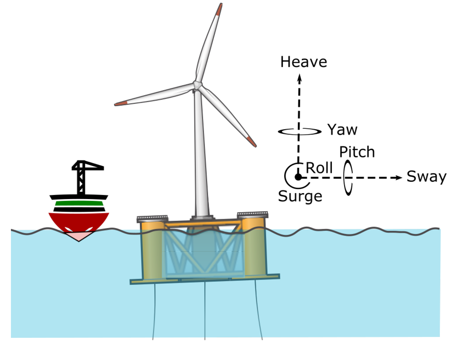
Figure 2.
Schematic of the methodology framework for evaluating O&M costs and availability for FOWT, showing the input and output space of integrated models UWiSE O&M Planner and SafeTrans.
Figure 2.
Schematic of the methodology framework for evaluating O&M costs and availability for FOWT, showing the input and output space of integrated models UWiSE O&M Planner and SafeTrans.
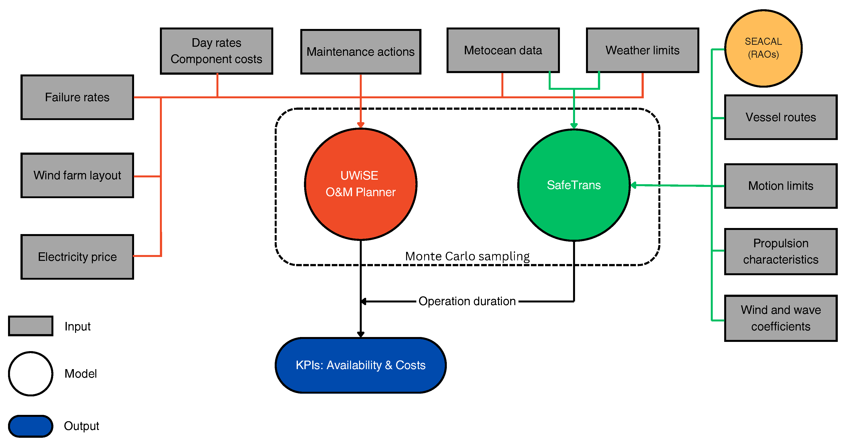
Figure 3.
Time series plots of mean wind speed () and significant wave height () for Marram Wind and Celtic Sea C, showing raw data (lighter shades) and moving averages (darker lines) calculated with a bin size of 1000.
Figure 3.
Time series plots of mean wind speed () and significant wave height () for Marram Wind and Celtic Sea C, showing raw data (lighter shades) and moving averages (darker lines) calculated with a bin size of 1000.
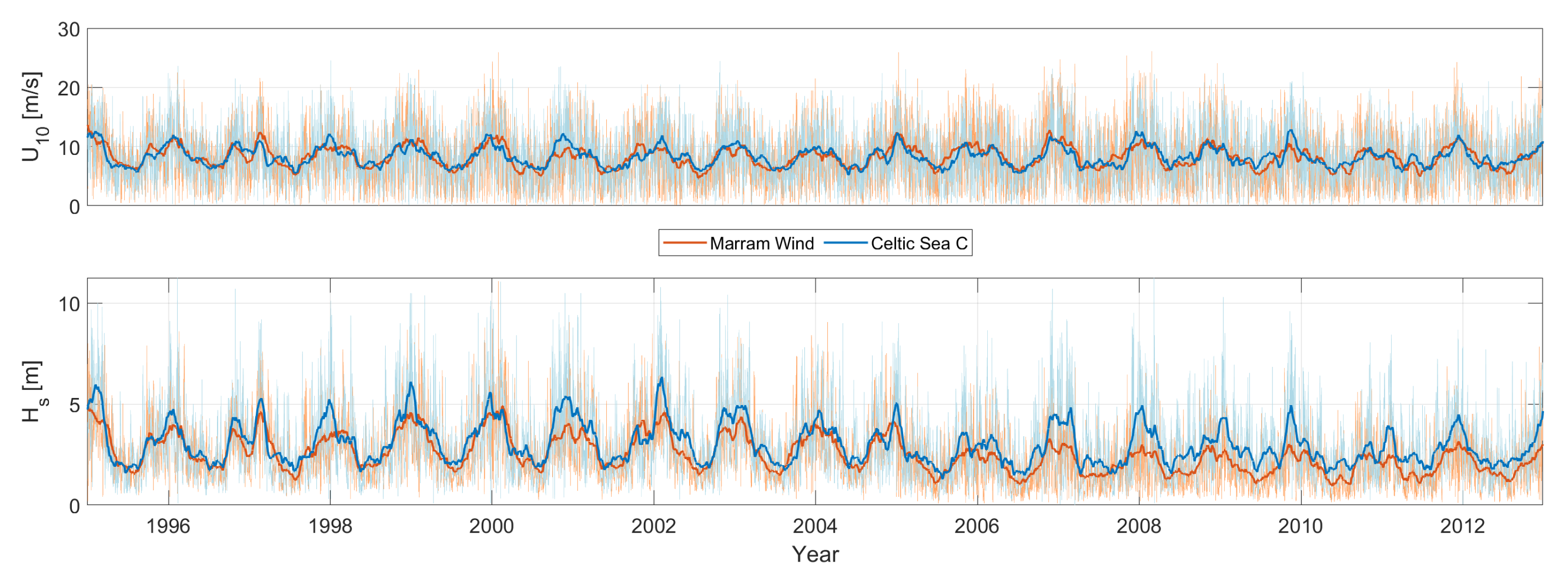
Figure 4.
KPIs for the T2P strategy at Marram Wind and Celtic Sea C sites, showing MDC and . The bars illustrate the breakdown of MDC into categories, including WTG Major & Minor Repair, WTG Major Component Replacement, Scheduled Maintenance, and Floating Substructure Maintenance. Revenue losses are plotted separately. MDC is the sum of the stacked plot and the plot for revenue losses for the respective wind farm. at Marram Wind is 94%, while at Celtic Sea C, it is 90%. Error bars indicate the variability in MDC estimates using 2 standard deviations.
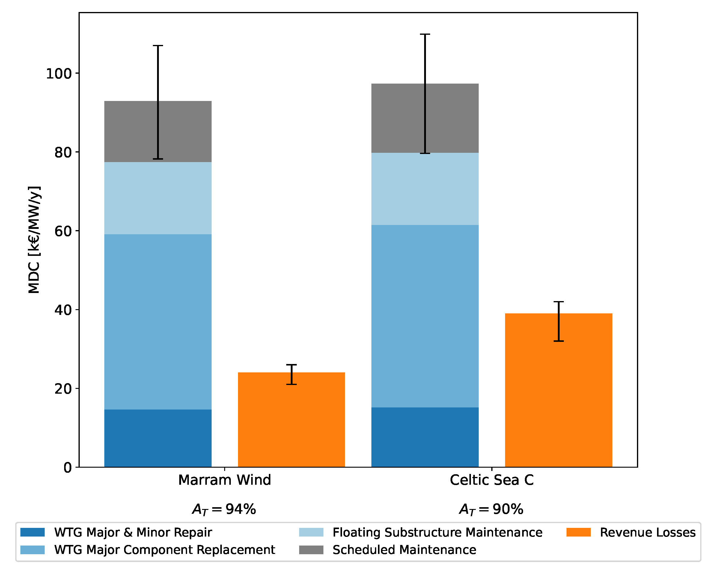
Figure 5.
Normalized MDC for MCR strategies (T2P, FTF, SHC) at Marram Wind and Celtic Sea C. Each site shows variations in MDC with different MCR strategies while keeping other O&M activities constant. Bars represent costs for vessels, technicians, spare parts, revenue losses, and values indicate time-based availability.
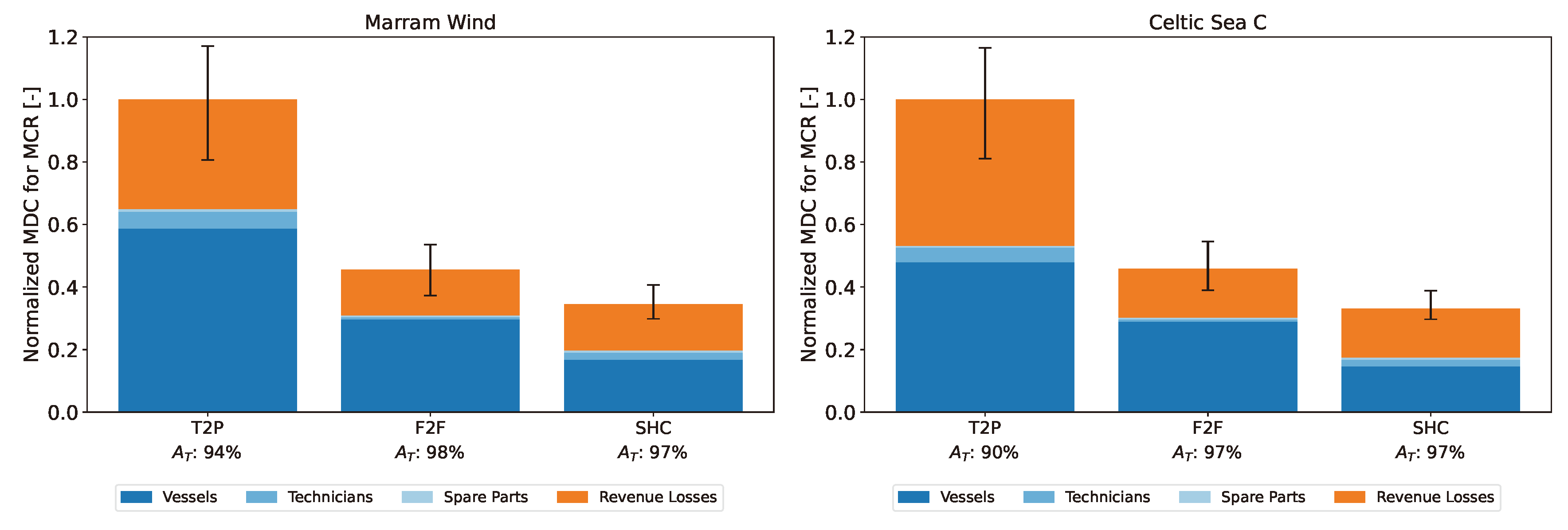
Figure 6.
Box plots of MCR operation durations for three strategies (T2P, FTF, SHC) at Marram Wind and Celtic Sea C sites. Blue and orange boxes represent UWiSE (weather limits only) and SafeTrans (weather and motion limits) simulations, respectively. Plots show the variability in MCR durations across different months, highlighting the impact of weather and motion constraints on each strategy’s performance.
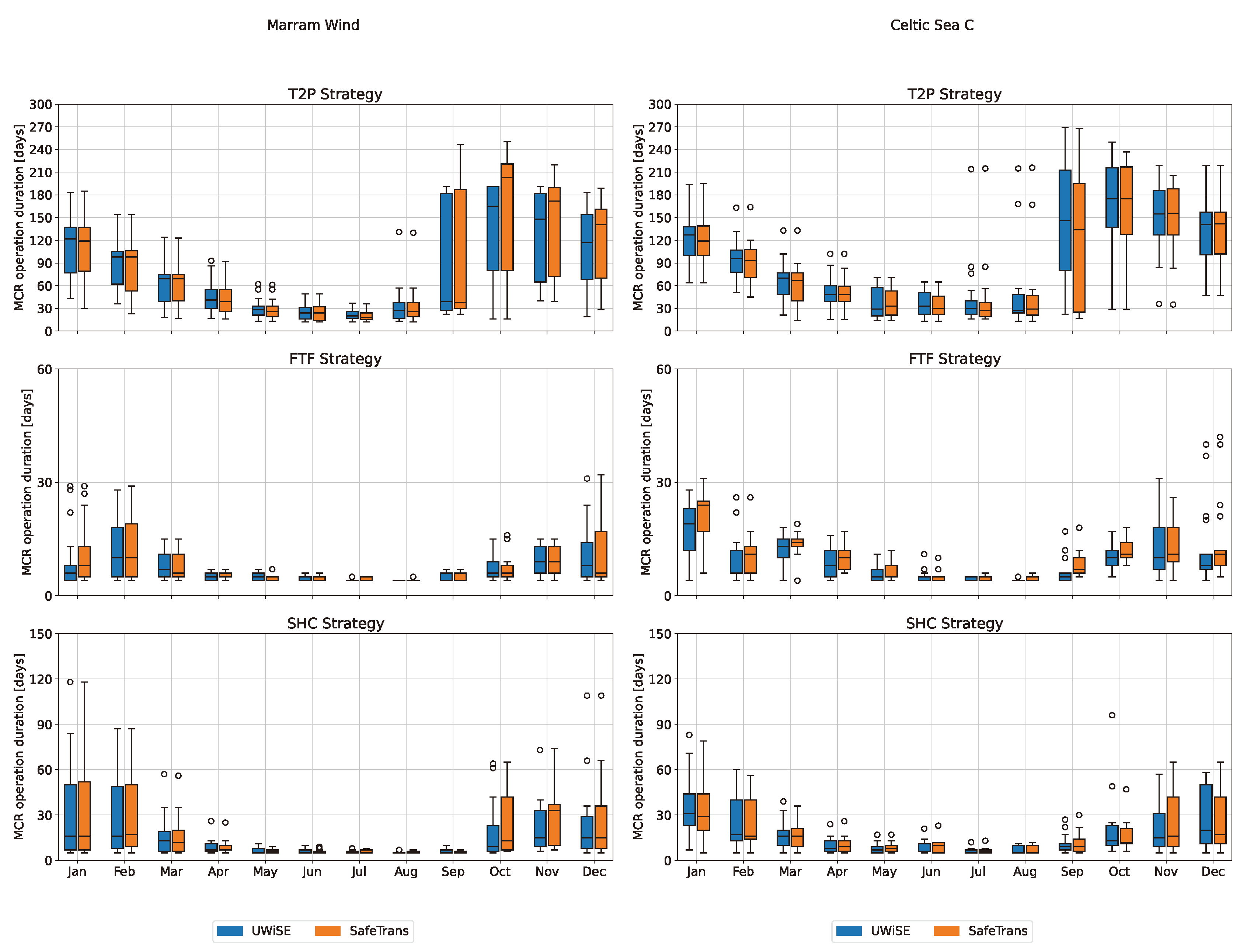
Figure 7.
Scatter plot comparing allowable significant wave height () limits for the "Tow WT to Port" step in the T2P strategy, determined by UWiSE (weather limits) and SafeTrans (motion limits). SafeTrans allows higher limits (above 3m) due to accounting for dynamic vessel responses, while UWiSE maintains conservative limits below 3m.
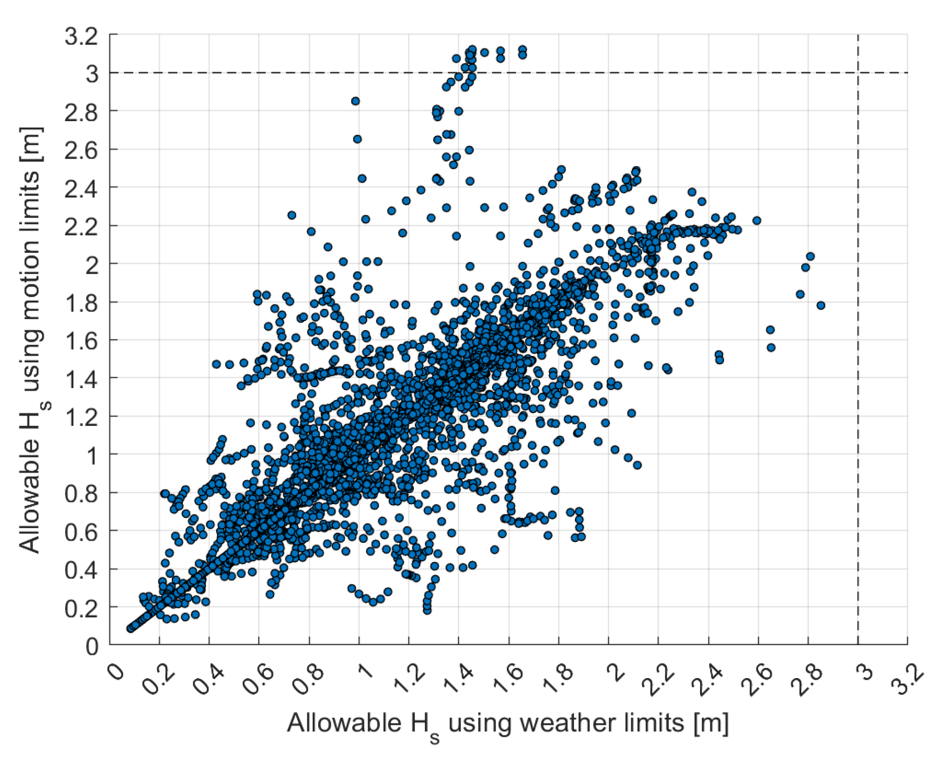
Table 1.
Overview of the wind farm characteristics for the case study.
| Wind farm characteristics | ||||
|---|---|---|---|---|
| Farm layout | 100 x 15 MW | |||
| Turbine | 15 MW NREL reference turbine | |||
| Floater | UMaine VolturnUS-S semi-submersible type | |||
| Location | North Sea: MarramWind | Celtic Sea: Celtic Sea C | ||
| Water depth | 87 - 117.5 m | 90 - 100 m | ||
| Port | Fraserburgh | Loughbeg | ||
| Distance to port | 96.83 km | 129.66 km | ||
Table 2.
Overview of the O&M characteristics. Abbreviations: MCR = Major Component Replacement, MR = Major Repair, mR = Minor Repair, AC = Annual Campaign, T = Technicians.
Table 2.
Overview of the O&M characteristics. Abbreviations: MCR = Major Component Replacement, MR = Major Repair, mR = Minor Repair, AC = Annual Campaign, T = Technicians.
| O&M characteristics | |||||
|---|---|---|---|---|---|
| Component | Maintenance | Failure rate | Cost (€) | Duration (hrs.) | Resources |
| Corrective Maintenance | |||||
| Direct Drive Generator | MCR | 0.009 | 236500 | 81 | 2 Tugs + AHT + 8T |
| MR | 0.03 | 14340 | 25 | SOV + 3T | |
| mR | 0.546 | 1000 | 7 | SOV + 2T | |
| Power Converter | MCR | 0.077 | 55000 | 57 | 2 Tugs + AHT + 4T |
| MR | 0.338 | 7000 | 14 | SOV + 3T | |
| mR | 0.538 | 1000 | 7 | SOV + 2T | |
| Main Shaft | MCR | 0.009 | 232000 | 48 | 2 Tugs + AHT + 5T |
| MR | 0.026 | 14000 | 18 | SOV + 3T | |
| mR | 0.231 | 1000 | 5 | SOV + 2T | |
| Power Electrical System | MCR | 0.002 | 50000 | 18 | 2 Tugs + AHT + 4T |
| MR | 0.016 | 5000 | 14 | SOV + 3T | |
| mR | 0.358 | 1000 | 5 | SOV + 2T | |
| Yaw System | MCR | 0.001 | 12500 | 49 | 2 Tugs + AHT + 5T |
| MR | 0.006 | 3000 | 20 | SOV + 3T | |
| mR | 0.162 | 500 | 5 | SOV + 2T | |
| Pitch System | MCR | 0.001 | 14000 | 25 | 2 Tugs + AHT + 4T |
| MR | 0.179 | 1900 | 19 | SOV + 3T | |
| mR | 0.824 | 500 | 9 | SOV + 2T | |
| Blades | MCR | 0.001 | 445000 | 288 | 2 Tugs + AHT + 21T |
| MR | 0.010 | 43110 | 21 | SOV + 3T | |
| mR | 0.456 | 5000 | 9 | SOV + 2T | |
| Active Ballast System | mR | 0.010 | 1000 | 8 | SOV + 2T |
| Mooring Lines | MCR | 0.013 | 135000 | 360 | AHT + CTV + 10T |
| MR | 0.015 | 20000 | 240 | AHT + CTV + 10T | |
| mR | 0.120 | 1500 | 40 | SOV + 5T | |
| Anchors | MCR | 0.013 | 512000 | 360 | AHT + CTV + 10T |
| MR | 0.015 | 75000 | 240 | AHT + CTV + 10T | |
| Inter Array Cable | MCR | 0.016 | 220000 | 360 | SOV + 10T |
| MR | 0.025 | 30000 | 240 | SOV + 10T | |
| Buoyancy Modules | MCR | 0.033 | 100000 | 40 | SOV + 5T |
| Export Cable | MR | 0.020 | 30000 | 60 | SOV + 5T |
| Preventive Maintenance | |||||
| WTG | AC | 1 | 1500 | 24 | SOV + 3T |
| Platform | AC (topside) | 1 | 600 | 24 | SOV + 4T |
| AC (underwater) | 0.5 | 1000 | 12 | SOV + 10T | |
Table 3.
Vessel characteristics used in the study, including day/wait (D/W) rates, mobilization/demobilization (M/D) rates, length between perpendiculars (), draft (T), displacement (), bollard pull (), and vessel speed (). *The speed of the Lead Tug Vessel when towing a FOWT is 4.0 kts, and the speed of the SHC platform when towed by the tug vessel is 6.8 kts.
| Vessel characteristics | |||||||
|---|---|---|---|---|---|---|---|
| Vessel | D/W rate | M/D rate | [m] | T [m] | [tons] | [tons] | [kts] |
| SOV (ROV Supported) | 75000 | 225000 | 84 | 5.0 | 6245 | 73 | 11.2 |
| AHT (CTV Assisted) | 66000 | 530000 | 88 | 7.3 | 7354 | 250 | 19.3 |
| AHT | 55000 | 500000 | 88 | 7.3 | 7354 | 250 | 19.3 |
| Lead Tug Vessel | 30000 | 200000 | 88 | 7.3 | 7354 | 250 | 19.3* |
| Assist Tug Vessel | 30000 | 200000 | 49.5 | 5.1 | 2290 | 100 | 9.8 |
| SHC assist Tug Vessel | 20000 | 150000 | 49.5 | 5.1 | 2290 | 100 | 9.8 |
| SSCV, operational | 290000 | 325000 | 120 | 22.5 | 49956 | 700 | 0.0 |
| SSCV, transit | 290000 | 325000 | 120 | 6.67 | 20959 | 700 | 8.0 |
| SHC platform, transit | 80000 | 160000 | 60 | 3.33 | 3947 | - | 6.8* |
| Onshore crane | 25000 | 185000 | - | - | - | - | - |
Table 4.
Tow-to-Port (T2P) strategy for MCR, detailing the duration of each activity in hours alongside the corresponding weather and motion limits. Vessel motion limits at the Center of Gravity (CoG) and towing limits at the wind turbine’s nacelle are provided for key operations. The limits are considered in UWiSE but not in SafeTrans during the transit and towing steps; the differences in results will be discussed in the next section.
 | ||||
|---|---|---|---|---|
| Vessels | Action | Duration (h) | Weather limits [, ] | Motion Limits |
| Lead tug + Assist tug + Onshore crane | Mobilize vessels | 24 | - | - |
| Transfer technicians | 1 | - | - | |
| Transit to site | distance/ vessel speed | [3, 12] | C1 | |
| Turn off WT | - | - | - | |
| Couple with WT | 8 | [1.75, 15] | C1 | |
| Disconnect MLs & IACs + joint IACs | 60 | [1.75, 15] | C1 | |
| Tow WT to port | distance/ towing speed | [3, 12] | C1 + C2 | |
| Quayside operation | 6 | - | - | |
| Replace component | MCR (hrs.) component | - | - | |
| Test & check WT | 3 | - | - | |
| Couple with WT | 8 | [1.75, 15] | C1 | |
| Quayside operation | 6 | - | - | |
| Tow WT to site | distance/ towing speed | [3, 12] | C1 + C2 | |
| Dejoint IACs | 12 | [1.75, 15] | C1 | |
| Reconnect MLs & IACs | 60 | [1.75, 15] | C1 | |
| WT pre run | 4 | - | - | |
| Turn on WT | - | - | - | |
| Transit to port | distance/ vessel speed | [3, 12] | C1 | |
| Transfer technicians | 1 | - | - | |
| Demobilize vessels | 24 | - | - | |
| Criteria | Response | RMS Limit | Unit | |
| Vessel motion limits at CoG [C1] | Surge acc. () | 1.3 | m/s² | |
| Sway acc. () | 1.3 | m/s² | ||
| Heave acc. () | 1.9 | m/s² | ||
| Roll () | 6 | deg | ||
| Towing limits at WT’s nacelle [C2] | Surge acc. () | 1.96 | m/s² | |
| Sway acc. () | 1.96 | m/s² | ||
| Roll () | 5 | deg | ||
| Pitch () | 5 | deg | ||
Table 5.
Floating-to-Floating (FTF) strategy for MCR, where the duration of the activities is indicated in hours. The table details the key actions involved in the FTF strategy, including transiting the SSCV to the site, performing the MCR operation on-site using the onboard crane, and transiting back to port. The weather limits and motion limits at the vessel’s CoG and the WT’s nacelle are specified. The limits are considered in UWiSE but not in SafeTrans during the transit step; the differences in results will be discussed in the next section.
 | ||||
|---|---|---|---|---|
| Vessels | Action | Duration (h) | Weather limits [, ] | Motion Limits |
| SSCV | Mobilize vessel | 24 | - | - |
| Transfer technicians component | 4 | - | - | |
| Transit to site | distance/speed | [4.5, 15] | C1 | |
| Turn off WT | - | - | - | |
| Ballast to draft & deploy crane | 4 | [3.5, 15] | C1 | |
| Replace component | MCR (hrs.) × 1.2 | [3.5, 15] | C1 + C3 | |
| WT pre run | 4 | - | - | |
| Turn on WT | - | - | - | |
| Transit to port | distance/speed | [4.5, 15] | C1 | |
| Transfer technicians component | 4 | - | - | |
| Demobilize vessels | 24 | - | - | |
| Criteria | Response | RMS Limit | Unit | |
| Vessel motion limits at CoG [C1] | Surge acc. () | 1.3 | m/s² | |
| Sway acc. () | 1.3 | m/s² | ||
| Heave acc. () | 1.9 | m/s² | ||
| Roll () | 6 | deg | ||
| Floating to floating limits at nacelle [C3] | Surge (X) | 1.5 | m | |
| Sway (Y) | 1.5 | m | ||
| Heave (Z) | 0.4 | m | ||
Table 6.
Self-Hoisting Crane (SHC) Strategy for MCR, where the duration of activities is indicated in hours. This table outlines the steps involved in executing the SHC strategy, detailing the associated weather and motion limits, with a particular focus on heave motion limits at the SHC platform deck to ensure safe and accurate operation during lifting activities. The limits are considered in UWiSE but not in SafeTrans during the transit step; the differences in results will be discussed in the next section.
 | ||||
|---|---|---|---|---|
| Vessels | Action | Duration (h) | Weather limits [, ] | Motion Limits |
| CTV + Small tug + Self hoisting crane | Mobilize vessel | 24 | - | - |
| Transfer technicians and component | 4 | - | - | |
| Tow SHC platform to site | distance/speed | [3,15] | C1 | |
| Turn off WT | - | - | - | |
| Couple SHC platform to WT | 1 | [2, 15] | - | |
| Install crane from platform to tower top | 3 | [3.5, 15] | - | |
| Replace component | MCR (hrs.) × 1.2 | [3.5, 15] | C4 | |
| Lower crane and preparation | 3 | [3.5, 15] | - | |
| Decouple SHC platform from WT | 1 | [2, 15] | - | |
| Turn on WT | - | - | - | |
| Tow SHC platform to port | distance/speed | [3,15] | C1 | |
| Transfer technicians and component | 4 | - | - | |
| Demobilize vessels | 24 | - | - | |
| Criteria | Response | RMS Limit | Unit | |
| Vessel motion limits at CoG [C1] | Surge acc. () | 1.3 | m/s² | |
| Sway acc. () | 1.3 | m/s² | ||
| Heave acc. () | 1.9 | m/s² | ||
| Roll () | 6 | deg | ||
| Self hoisting crane criteria at SHC platform deck [C4] | Heave (Z) | 0.4 | m | |
Disclaimer/Publisher’s Note: The statements, opinions and data contained in all publications are solely those of the individual author(s) and contributor(s) and not of MDPI and/or the editor(s). MDPI and/or the editor(s) disclaim responsibility for any injury to people or property resulting from any ideas, methods, instructions or products referred to in the content. |
© 2024 by the authors. Licensee MDPI, Basel, Switzerland. This article is an open access article distributed under the terms and conditions of the Creative Commons Attribution (CC BY) license (http://creativecommons.org/licenses/by/4.0/).
Copyright: This open access article is published under a Creative Commons CC BY 4.0 license, which permit the free download, distribution, and reuse, provided that the author and preprint are cited in any reuse.


