Submitted:
01 October 2024
Posted:
02 October 2024
You are already at the latest version
Abstract
The sciences related to production engineering consider many aspects related to cyber physical systems (CPS), in particular robots, treating them as implementations of the Industry 4.0 con-cept. The construction of CPS remains the domain of various engineering disciplines - mechan-ics, control theory or computer science. The problem of communication occurring during the implementation of the control of a single robot understood as a CPS object may concern the ex-change of data within a CPS or between different CPSs. In this area, software and hardware compatibility problems arise. Therefore, the paper presents a modular application for the ex-change of process data between mechatronic devices such as robots, which solves this problem. The work is complemented by an example of the use of the presented application in communi-cation between a mobile wheeled robot with Macanum wheels and a quadruped robot based on a motion capture system. It was assumed that the control of the wheeled robot would be realized from the perspective of implementing the basic robotics task of driving to a target, while the quadruped robot, representing a moving target, together with the motion capture system, would constitute a CPS whose outputs are incompatible in a software and hardware sense. With this choice of example, main attention was focused on the particular importance of multidisci-plinary in the context of the communication problem and also provide an application that al-lows for a modular solution to the problem of software/hardware compatibility in the commu-nication problem. This, in turn, is of interest to researchers associated with various engineering disciplines.
Keywords:
cyber-physical systems
; wheeled mobile robots
; motion capture
; communication
1. Introduction
In mid-July 2023, the Web of Science database contained around 30 papers from the past five years, which included the phrases Industry 4.0 and review in their title and were cited at least 100 times. This leads us to believe that Industry 4.0 is a present-day research topic, despite emerging proposals to develop Industry 4.0 with a human component, creating the concepts of Industry 5.0 [1]. Its aim is synergy between humans and autonomous machines [2].
Further confirmation of the topicality of Industry 4.0 can be found in the work of [3]. The authors point out that currently Industry 4.0 does not have an agreed definition, which creates serious limitations in building Industry 4.0 theory and comparing research in this area. Through a literature review that analyses almost 100 definitions of Industry 4.0 and related concepts, the authors point out similarities and differences between definitions based on the categories adopted. It seems that the multiplicity of definitions is a good measure of the timeliness of the research because it clearly indicates the ongoing discussion and development of the Industry 4.0 topic. The authors themselves indicate [3] that their work is intended to be a contribution to further discussion and that the adopted categorization is intended to organize future research on the approach to Industry 4.0 in its many aspects.
As it is pointed out in work [4], Industry 4.0 is characterized by highly developed automation processes that incorporate the achievements of electronics and IT. From a production and service management perspective, Industry 4.0 focuses on the creation of intelligent and communicating systems, such as Machine-to-Machine (M2M) and Human-Machine Interaction (HMI), with the ability to communicate with other intelligent and distributed systems. The author [4] in works [5,6,7] describes the nine pillars of Industry 4.0. These are: Industrial Internet of Things, cloud computing, Big Data, simulation, augmented reality, additive manufacturing, horizontal and vertical systems integration, autonomous robots and cyber security. This list indicates that research into the concept of Industry 4.0 is not only topical but also interdisciplinary.
The concept of Industry 4.0 is concretized in cyber-physical systems, which by one definition are a combination of embedded systems and physical objects. Embedded (computational) systems control physical processes, usually with feedback loops in which physical processes influence computation and vice versa [8,9]. Review paper [8] presents the concepts and characteristics of CPS and indicates further research perspectives in this area. The authors point out that research on CPS is just beginning and is multidisciplinary in nature. This is due to the fact that CPS is heterogeneous system without a unified global model. Therefore, research on CPS is being conducted by experts from different disciplines, focusing on system architecture, information processing and software design. This is confirmed, among other things, in the work [9], which discusses which models should be used for CPS, since these combine different scientific and engineering disciplines.
In line with research on Industry 4.0 and its implementation in the form of a CPS, this paper is aimed at addressing the topic of communication between hardware and software incompatible components of CPSs or between CPSs themselves. A proposed modular data processing application and an example of its application in mobile robotics—in the task of reaching a changing target, which is another robot—will be presented. The communication between the CPSs, i.e., the mobile robot and the quadruped robot, is realized using incompatible protocols and a motion capture system that gives the positions of the quadruped robot and also tracks (to verify the odometry measurement) the positions of the mobile robot. In the next section, the assumptions of the proposed application and selected technical details will be presented. Its use in an environment composed of two robots will be the content of the next section. The article will conclude with a presentation of the results of the conducted research and a summary.
2. Communication Compatibility
In review summary [10] it was noted that the main technical enablers that underpin Industry 4.0, or are directly related to it, come from information and communication technologies. These technologies enable communication between CPSs and between CPS components. In the work [9] Figure 1a shows a diagram of a simple CPS composed of two embedded systems that interact with a physical object via sensors and actuators and with each other via a specific communication method. In the paper [9] this is a factory network.
Figure 1b schematically shows the three CPSs interacting with each other. When communicating within a CPS structure as well as between them, a hardware-software compatibility problem may arise. The proposed application is intended to act as an agent, by introducing a hardware-software solution that will agree on the communication within or between the CPSs. Such a situation is shown in Figure 2a,b for communication between components of a CPS and between several CPSs.
The proposed approach to implement an agent is an application with an input-output architecture, as it is assumed that the agent can transfer data from multiple inputs to a single output. The adoption of such an architecture determines the unidirectional nature of the communication. However, this problem is eliminated by another assumption about the agent: inputs and outputs are to be configurable on the basis of interchangeable hardware-software modules. Bidirectional communication then requires only a duplication of the number of agents operating unidirectionally. Interventionary studies involving animals or humans, and other studies that require ethical approval, must list the authority that provided approval and the corresponding ethical approval code.
In summary, the proposed agent should meet several objectives:
- it should be capable of transferring data between different interfaces in the hardware/software sense in one direction,
- should be able to support various protocols, through software and hardware modules,
- should be configurable, i.e., it allows the type of input and output to be specified,
- should allow the transmission of data from multiple inputs in a sequential or parallel manner,
- should ensure the time independence of the handling of a given input and output,
- should be multiplatform
Given the assumptions made, the following sections describe selected implementation details of the proposed agent, RoboDataLink.py, and an example of its use.
3. Agent—RoboDataLink.py Application
As indicated earlier, communication between different systems or their components is one of the challenges in the application of the Industry 4.0 concept, of which CPS is a key solution. On a small scale, these problems have been noted in the work of the team at the Department of Applied Mechanics and Robotics to which the authors belong. The team is working on the control of mobile robots using, among other things, rapid prototyping methods based on the dSpace signal processor. Its direct integration with sensors such as lidar, IMU or the Vicon motion capture system is limited by software and hardware compatibility.
As a first step in the development of an application connecting incompatible devices, LeicaConnector.py was used to communicate with the Leica laser tracker [11]. The work describes the possibility to connect the Leica AT960 laser tracker to any device that communicates over Ethernet and does not have direct support for the tracker API. The program, which was realized in Python, had two threads. One of them communicated with the tracker based on the API provided by the manufacturer, while the other distributed measurement data based on the TCP/IP standard. Data exchange between threads was based on a shared buffer, implemented as an array.
The agent application described here, with the working name RoboDataLink.py, is a generalization of LeicaConnector.py. As the name implies, it was written in Python, supported by features of the language such as its popularity, multiplatformity and wide availability of libraries. The application’s interface was developed as a TUI (Terminal User Interface).
RoboDataLink.py (source code is available: github.com/ppenar/robo-data-link) assumes (Figure 3) that there can be many different inputs distributing data, the configuration of which is variable. From a program perspective, each is an independent module (programmatically they are threads) communicating with a physical device/program/data source. A module is created by implementing specific methods in a class whose instance is instantiated as a thread. The implementation of the module stores the data to be passed to the output in a buffer, which is implemented using an array of numbers of type int16. It is a shared element between input and output and defines the data frame. The output is another thread. It should be noted that the implementation of the input module may include an algorithm for processing the data before writing it to the shared buffer.
This approach to the application architecture allows for time independence of each input and between inputs and outputs, making it possible to integrate data exchange standards operating at different speeds.
Like inputs, the output of RoboDataLink.py can support different communication standards. This requires the implementation of specific methods in the class whose instance is run as a thread (Figure 3). In addition, the output must specify how to retrieve data from the buffer, which can be passed to the output sequentially or in parallel by combining buffers (frames) from multiple inputs.
So far, several input modules have been implemented, i.e., to support the Motion Capture Vicon system, the Lidar RPLIDAR S1 and a test module that generates random numbers. The data received by the input modules (after optional processing) is stored in a buffer. This is necessary due to the time independence of the inputs and outputs, but this approach can lead to delays in updating the RoboDataLink output.
The output from the RoboDataLink application, can be implemented based on serial communication in the RS232 standard or the Ethernet standard. The choice of the output type and its configuration is also specified in the configuration file.
4. Tests of the RoboDataLink.py Agent
The program described in the previous section, which acts as an agent for communication between incompatible CPSs, was tested in a laboratory environment. This consisted of two CPSs (Figure 4). The first is the four-wheeled mobile robot Panther with Mecanum wheels from Husarion [12] (physical object) together with a Dspace DS1103 control and measurement card (embedded system) operated by a PC. The second CPS system is a Unitree GO1 quadruped robot (physical system) together with a motion capture system from VICON determining the robot’s positions.
4.1. Research Environment
The Panther robot (Figure 5a) is equipped with four Mecanum wheels with a radius of 85 [mm]. The dimensions of the robot are: 805 × 840 × 290 [mm] (length and width of the robot and height of the platform). The weight of the vehicle is 55 [kg] and its maximum payload is 80 [kg]. The robot has four BLDC 80PMB800K.80RBL motors (rated at 473 [W] each) with planetary gears and incremental encoders. The vehicle includes an internal control computer: Raspberry Pi 4B with Broadcom BCM2711 processor and a power source in the form of 36 [V] lithium-ion batteries. The maximum speed of the robot is: 2 [m/s] and the torque rating of each drive module is 34.5 [Nm].
For this experiment, a Dspace DS1103 control and measurement card was used to control the wheeled robot. The card allows the measurement and acquisition of data coming from encoders and distributed via the RS232 standard, and the real-time generation of control signals for the motors (PWM signal) that drive the Mecanum wheels. The control algorithm is generated in the Matlab/Simulink environment. The program is then compiled to the level of optimized code in C using the RTW (Real Time Workshop) package. Its implementation into the Dspace board is made possible using the RTI (Real Time Interface) package [13].
The Unitree GO1 quadruped robot (Figure 5b) has 12 degrees of freedom (consisting of 12 servos). The manufacturer indicates that the robot has the ability to control the position of each joint. This makes it possible to realize force control of the whole robot [14]. The GO1 control itself can be realized manually using the supplied joystick or programmatically, using an API in C or Python language [14]. The program that implements the robot’s movement is run on an external PC or on one of the embedded systems. These include a Raspberry PI computer and three Nvidia Jetson chips. The latter are connected to five cameras that form part of the robot’s sensorics. Software access to the images from the cameras can be realized through a provided API. The same software layer allows the use of other sensorics components: joint-related encoders, an IMU chip and distance sensors.
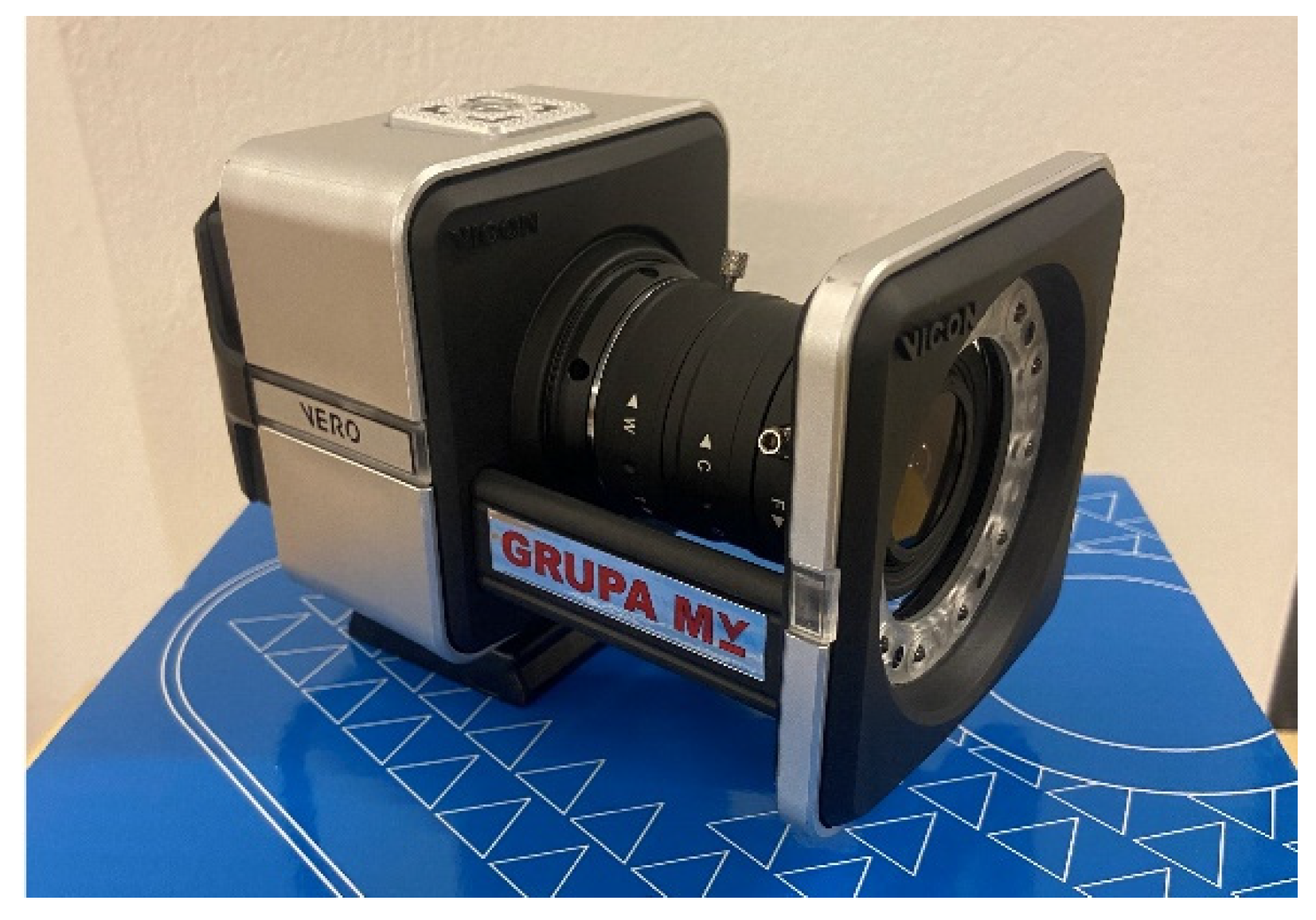
The Vicon motion capture measurement system used in the research allows accurate measurement of the tracked object based on a set of cameras tracking the position of markers placed on the tracked object. The entire system is equipped with 10 Vicon Vero v2.2 cameras, and it is not necessary for all of them to be used to carry out the measurements [15]. Each camera has a Vicon 6-12 [mm] zoom lens, the camera resolution is 2.2 [MP] (2048x1088) and the frame rate is 330 [Hz]. The minimum viewing angle of the camera for the telephoto lens is: 44.1° x 22.6° (horizontal to vertical), and for a wide-angle lens: 98.1° x 50.1°. The camera latency is 3.6 [ms] and the weight is approximately 0.5 [kg]. The cameras are equipped with an accelerometer to support the calibration process and a temperature sensor. Connectivity to the cameras is possible using an RJ45 connector. The signals from all cameras go to the PoE Switch, which is connected to the computer. Then, using the Tracker 3.9 software [15] it is possible to track, in real time, the position of an object with an accuracy of part of a millimeter [16].
Figure 6.
Vicon Vero camera used for provided research.
As can be seen from the diagram in Figure 4, the agent in the example under consideration enables the transmission of object position data tracked by Vicon’s motion capture system. In this configuration (Figure 7a), the input to the agent is the motion capture system and the thread associated with it processes the data from Vicon based on the UDP standard. The Vicon system tracked the position of the quadruped robot and the mobile robot (this measurement was only used to verify the measurement from odometry). In the Tracker program, dictated to the Vicon system, the IDs of the tracked robots were specified as 1pies and 2hus. The output of the RoboDataLink.py program is a frame that is transmitted via the RS232 standard to the Dspace card. Its structure is shown in Figure 7b. In the first three fields of the frame, the translation (in millimeters) of the object relative to the underlying coordinate system is transmitted. The next three elements of the frame are the rotation (in radians) multiplied by one hundred and projected to ensure accuracy when projected onto integers. It should be noted that one frame contains position and orientation information for only one object, which means that the position information of the robots was delivered to the Dspace measurement card alternately. Which robot the frame refers to is derived from the values of half 7 and 8 of the frame, i.e., 100+ID, where ID corresponds to the digit preceding the name of the tracked robot. e.g., for object 1dog, the value of fields 7 and 8 is 101. The last field of the frame is the checksum calculated as the arithmetic mean of the translations projected to integer values (i.e., round((transX+transY+transZ)/3)).
As the processing times of the input and output threads (implemented programmatically as a delay function in an infinite loop) can be different, the link between the aforementioned threads is the buffer into which the frame is written.
4.2. Control Algorithm for a Mobile Wheeled Robot
The control algorithm of the Mecanum mobile wheeled robot performed the task of following a moving target, which was a quadruped mobile robot. In robotics, this task is called following a moving target.
In the literature, this task is often implemented together with an obstacle avoidance task to enable autonomous vehicle movement in an unknown environment. Most often, the task of following a target is implemented based on methods: machine learning [18,19,20], fuzzy logic [18,21] artificial potential fields [22,23], predictive control [24] or behavioral [19,20,21,22,25]. Based on the scientific output of the team at the Department of Applied Mechanics and Robotics on the topic of autonomous motion control of a mobile robot [22,23,26] a behavioral hierarchical robot control system was developed, taking into account the holonomy of the Mecanum wheeled robot and the time-varying position of the target.
The control system consists of two layers: an outer and an inner layer (Figure 8). The outer layer enables the generation of the robot’s motion trajectory, which fulfils the task of following a preset moving target. The inner layer generates a control signal that enables the robot to follow the motion trajectory generated in the outer layer.
The outer layer uses a behavioral algorithm to allow the task: “follow the target”. To fulfil this task, distances were first determined between the position of the target, which is the quadruped robot, and the position of the mobile robot:
This is example 1 of an equation:
where: —the position of the centre of gravity of the Mecanum wheeled mobile robot relative to a stationary xy reference system, —position of the target, which is the characteristic point belonging to the mobile robot relative to the stationary xy reference system.
Figure 9.
Position of mobile robot and target.
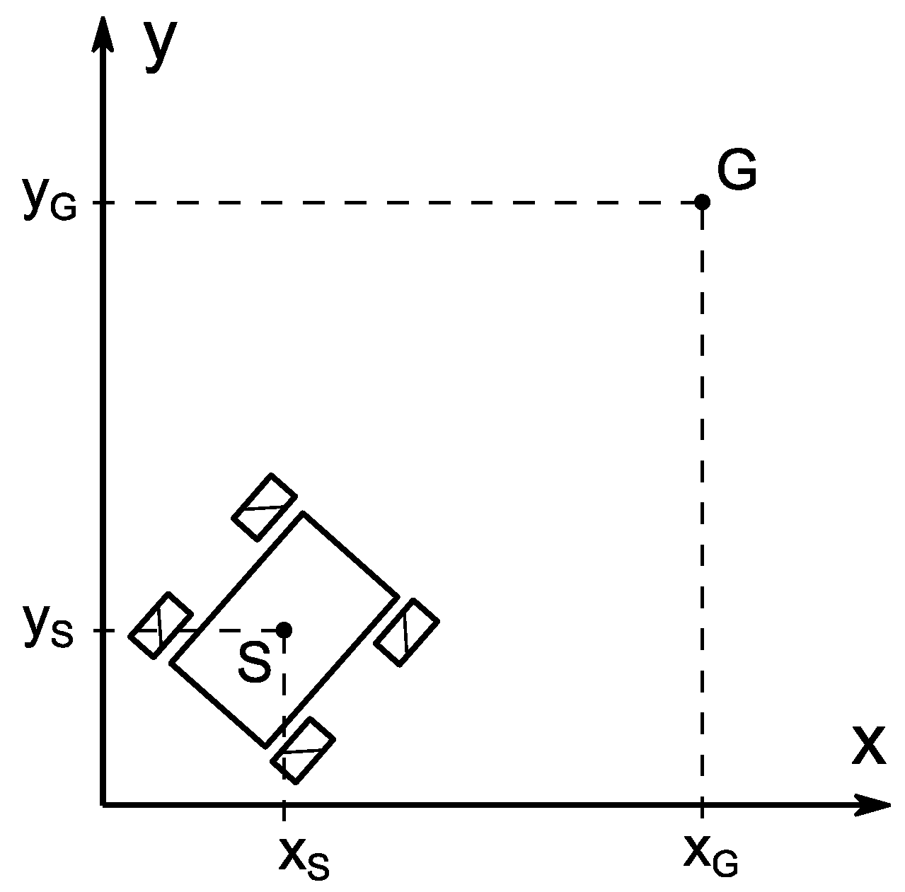
The position of the mobile robot was determined by reading the angular velocities of the robot wheels from the encoder sensors, while the positions of the target were read out based on the motion capture system used.
Based on the determined distance of the robot from the target (1), robot speed control signals were generated:
The control signal value has been scaled so that: , while maintaining the direction of the total vector of the speed control signal:
In the next step, the motion trajectory of the mobile robot with Mecanum wheels was generated. The velocity of the robot’s center of gravity was determined relative to a stationary xy coordinate system was determined:
where: —maximum linear velocity, which is given by the formula: .
Based on the kinematics model of the four-wheeled mobile robot with Mecanum wheels [25] and equation (3), the inverse kinematics was solved by generating the angular velocities of the Mecanum wheels:
where: —angular velocities of the Mecanum wheels, —angle of orientation of the robot frame, —angular velocity of the robot frame, —width of the robot platform, —distance between the characteristic point being the robot’s center of gravity and the front and rear axes of the robot, —radius of the Mecanum wheel, —radius of the roller.
Due to the Mecanum wheeled robot’s classification as a holonomic object, it is able to achieve any given linear velocity in two-dimensional space without having to change the orientation angle of the vehicle frame. Therefore, the rotation angle of the robot frame was assumed to be constant at zero: .
The angular velocities of the wheels obtained from equation (4) will be used as set motion parameters in the internal control layer.
In the inner layer of the control system, a tracking control task was performed, in which the angular parameters of the Mecanum wheels are supposed to follow the set angular parameters generated from the outer layer. In order to perform this task and to demonstrate the effectiveness of the developed control algorithm, one of the simplest control algorithms was used in the form of a PD controller, described by the formula:
where: —diagonal matrix of the differential gain. The generalised error and tracking error e, are defined by the relations:
where: —the vector of set angles of rotation of the Mecanum wheels, —vector of realised angles of rotation of the Mecanum wheels, —diagonal matrix with positive elements .
Based on realised rotation angle of the Mecanum wheels read from the encoders and on the robot’s movement trajectory generated in the outer layer, it is possible to control the mobile robot so that it carries out the task of following a moving target.
4.3. Results
In the experimental study, the target, which was a quadruped robot, was controlled manually. Together with the motion capture system Vicon, which determined its positions, it constituted a single CPS. The Panther mobile robot, which was tasked with autonomously following the moving target based on the reading of its position from encoder sensors placed on the motor shaft driving the Mecanum wheels, constituted a second CPS. Data exchange, i.e., the position reading of the Unitree GO1 robot in the Dspace card, was possible through the use of an agent, i.e., the RoboDataLink.py application.
Figure 10, Figure 11, Figure 12 and Figure 13 show the experimental results of how the task of following moving target by the mobile robot is achieved by using the outer layer of the control system (Figure 10 and Figure 12) as well as the inner layer (Figure 13). Figure 10 shows the waveforms describing the position of the mobile robot and the target with respect to the axis of the stationary xy coordinate system. It can be seen from Figs. 10a and 10b that the position of the mobile robot changes over time, following the position of the moving target. The fact that the coordinates of the mobile robot do not reach the position of the quadruped robot is due to the need to maintain a safe distance between the robots. The apparent distortion of the target position waveform occurring around 40 [s] is due to a temporary misreading of the position generated from the motion capture system, which may have been caused by the obscuration of the markers placed on the quadruped robot.
Figure 11 shows the motion track read from the encoders and the motion track read from the motion capture system. The position of the robot from the motion capture system was used to verify the odometry measurement of the robot. Position determination by the Vicon system was performed by the RoboDataLink.py application, as part of the described communication between the CPS systems described in Section 3.1. The obtained waveforms are analogous in shape, but there is a relative shift of the graphs by approximately 0.75 [m] with respect to the y-axis. The reason for this situation is most likely the temporary loss of contact between the Mecanum wheels and the ground that was observed during the experimental tests.
Figure 12a shows the distances between the position of the target and the position of the mobile robot.
Based on the distance measurement, a robot speed control signal is generated (Figure 12b). A motion trajectory is then generated, from which the obtained Mecanum wheel rotation angles (Figure 12c) and angular velocities (Figure 12d) are sent to the internal control layer. In Figure 12a, the apparent distance to the target, excluding the initial phase of movement, oscillates between -2 and 2 [m], indicating that the robot is effectively trying to follow the changing position of the target. In Figs. 12c and 12d, the generated waveforms of the angular motion parameters are the same for the wheel pair 1, 4 and 2, 3. This is due to the assumption made regarding the constant orientation angle of the robot frame (). The angular velocities of the Mecanum wheels assume a non-zero value in the final phase of the experiment. This is due to the fact that the position of the target is continuously variable, so that the mobile robot does not perform a braking process before the end of experiment. The maximum accepted duration of the experiment was approximately 45 [s], after which time the robot stopped.
Figure 13a shows the waveforms of the control signals generated by the PD controller in the inner layer of the control system. The waveforms of the Mecanum wheel angle tracking error (Figure 13b) and angular velocity (Figure 13c) are relatively small and limited, which indicates the stability of the control system. The sudden increase in angular velocity error observed at about 40 [s] is due to the occurrence of the previously discussed error in reading the target position affecting the sudden change in the set angular parameters of the robot’s movement.
The presented experimental results confirm the effectiveness of the presented control algorithm in performing the task of following a moving target. Furthermore, the experiment confirmed the feasibility of using RoboDataLink.py as an agent for communication between CPS systems.
5. Summary
This paper presents a possible solution to one of the problems of implementing the idea of Industry 4.0, which is the hardware-software incompatibility occurring in communication. The proposed application solves the problem of hardware-software compatibility in communication between CPS (cyber-physical system) components or between CPSs. The program RoboDataLink.py works in an input-output architecture and, through a modular thread-based design, allows easy implementation of new input-output communication standards. Its usefulness was verified in an experiment consisting of: two robots (a mobile robot with Mecanum wheels and a quadruped robot) and a motion capture system. The experiment carried out the task: following a moving target, based on a hierarchical, behavioral control system. The RoboDataLink.py application used in the test provided communication between the two CPSs. An agent in the form of RoboDataLink.py was used to ensure hardware-software compatibility between the motion capture system and the Dspace signal card. While this paper has demonstrated the usefulness of the author’s RoboDataLink.py application in the context of an Industry 4.0 implementation, the authors see room for development of the solution presented. This is the implementation of a graphical interface with an editor for configuration files, testing in virtual environments or direct connection to the Matlab/Simulink engineering environment. In addition, in future research work, the authors intend to extend the functionality of the mobile robot control algorithm with an obstacle avoidance function realized through the use of Lidar. In order to achieve software and hardware compatibility with, for example, the Dspace card, the RoboDataLink.py application will be used.
Author Contributions
Conceptualization, P.P. and M.S.; methodology, P.P. and M.S.; software, P.P.; validation, M.S.; formal analysis, A.G.; investigation, P.P. and M.S.; resources, P.P.; data curation, M.S.; writing—original draft preparation, P.P. and M.S.; writing—review and editing, A.G.; visualization, P.P.; supervision, A.G.; project administration, A.G.; funding acquisition, A.G. All authors have read and agreed to the published version of the manuscript.
Funding
This research received no external funding.
Conflicts of Interest
The authors declare no conflicts of interest.
References
- Pizoń, J.; Gola, A. The Meaning and Directions of Development of Personalized Production in the Era of Industry 4.0 and Industry 5.0. In: Machado, J., et al. Innovations in Industrial Engineering II. icieng 2022. Lecture Notes in Mechanical Engineering. 2023, Springer, Cham. [CrossRef]
- Nahavandi, S. Industry 5.0—A Human-Centric Solution. Sustainability 2019, 11, 4371. [Google Scholar] [CrossRef]
- Culot, G.; Nassimbeni, G.; Orzes, G.; Sartor, M. Behind the Definition of Industry 4.0: Analysis and Open Questions. International Journal of Production Economics 2020, 226, 107617. [Google Scholar] [CrossRef]
- Alcácer, V.; Cruz-Machado, V. Scanning the Industry 4.0: A Literature Review on Technologies for Manufacturing Systems. Engineering Science and Technology, an International Journal 2019, 22, 899–919. [Google Scholar] [CrossRef]
- Motyl, B.; Baronio, G.; Uberti, S.; Speranza, D.; Filippi, S. How Will Change the Future Engineers’ Skills in the Industry 4.0 Framework? A Questionnaire Survey. Procedia Manufacturing 2017, 11, 1501–1509. [Google Scholar] [CrossRef]
- Asaad, H.; Askar, S.; Kakamin, A.; Faiq, N. Exploring the Impact of Artificial Intelligence on Humanrobot Cooperation in the Context of Industry 4.0. Applied Computer Science 2024, 20(2), 138–156. [Google Scholar] [CrossRef]
- Saucedo-Martínez, J.A.; Pérez-Lara, M.; Marmolejo-Saucedo, J.A.; Salais-Fierro, T.E.; Vasant, P. Industry 4.0 Framework for Management and Operations: A Review. J Ambient Intell Human Comput 2018, 9, 789–801. [Google Scholar] [CrossRef]
- Liu, Y.; Peng, Y.; Wang, B.; Yao, S.; Liu, Z. Review on Cyber-Physical Systems. IEEE/CAA J. Autom. Sinica 2017, 4, 27–40. [Google Scholar] [CrossRef]
- Lee, E. The Past, Present and Future of Cyber-Physical Systems: A Focus on Models. Sensors 2015, 15, 4837–4869. [Google Scholar] [CrossRef]
- Aceto, G.; Persico, V.; Pescape, A. A Survey on Information and Communication Technologies for Industry 4.0: State-of-the-Art, Taxonomies, Perspectives, and Challenges. IEEE Commun. Surv. Tutorials 2019, 21, 3467–3501. [Google Scholar] [CrossRef]
- Szybicki, D.; Obal, P.; Penar, P.; Kurc, K.; Muszyńska, M.; Burghardt, A. Development of a Dedicated Application for Robots to Communicate with a Laser Tracker. Electronics 2022, 11, 3405. [Google Scholar] [CrossRef]
- Robot Panther Manual Available online:. Available online: https://husarion.com/manuals/panther/ (accessed on 18 September 2024).
- dSpace, DS1103 PPC Controller Board. Hardware Installation and Configuration; 2004.
- Go1 Documentation, Available online: https://unitree-docs.readthedocs.io/en/latest/get_started/Go1_Edu.html.
- Vicon Tracker User Guide, Available online: https://help.vicon.com/space/Tracker39.
- Vicon Accuracy in Motion, Available online: https://www.vicon.com/wp-content/uploads/2022/07/Vicon-Metrology-Solutions.pdf.
- Camera Vicon Vero. Technical Information. Available online: https://www.vicon.com/hardware/cameras/vero/#technical-information.
- Boubertakh, H.; Tadjine, M.; Glorennec, P.-Y. A Simple Goal Seeking Navigation Method for a Mobile Robot Using Human Sense, Fuzzy Logic and Reinforcement Learning. In Proceedings of the Knowledge-Based Intelligent Information and Engineering Systems; Lovrek, I., Howlett, R.J., Jain, L.C., Eds.; Springer Berlin Heidelberg: Berlin, Heidelberg, 2008; pp. 666–673. [Google Scholar]
- Motlagh, O.; Nakhaeinia, D.; Tang, S.H.; Karasfi, B.; Khaksar, W. Automatic Navigation of Mobile Robots in Unknown Environments. Neural Comput & Applic 2014, 24, 1569–1581. [Google Scholar] [CrossRef]
- Hendzel, Z.; Szuster, M. Neural Sensor-Based Navigation of Wheeled Mobile Robot in Unknown Environment. Pomiary Automatyka Robotyka 2013, 17, 114–120. [Google Scholar]
- Hendzel, Z. Fuzzy Reactive Control of Wheeled Mobile Robot. Journal of Theoretical and Applied Mechanics 2004, 42, 503–517. [Google Scholar]
- Goeller, M.; Steinhardt, F.; Kerscher, T.; Zöllner, J.M.; Dillmann, R. Proactive Avoidance of Moving Obstacles for a Service Robot Utilizing a Behavior-Based Control.
- Kerr, E.P.; Vance, P.; Kerr, D.; Coleman, S.A.; Das, G.P.; McGinnity, T.M.; Moeys, D.P.; Delbruck, T. Biological Goal Seeking. In Proceedings of the 2018 IEEE Symposium Series on Computational Intelligence (SSCI); IEEE: Bangalore, India, November 2018; pp. 1602–1607.
- Moreno-Caireta, I.; Celaya, E.; Ros, L. Model Predictive Control for a Mecanum-Wheeled Robot Navigating among Obstacles. IFAC-PapersOnLine 2021, 54, 119–125. [Google Scholar] [CrossRef]
- Benbouabdallah, K.; Zhu, Q.-D. A Behavior-Based Controller for a Mobile Robot Tracking a Moving Target in Multi-Obstacles Environment. In Proceedings of the 2013 5th International Conference on Intelligent Human-Machine Systems and Cybernetics; IEEE: Hangzhou, China, August 2013; pp. 418–423.
- Szeremeta, M.; Szuster, M. Neural Tracking Control of a Four-Wheeled Mobile Robot with Mecanum Wheels. Applied Sciences 2022, 12, 5322. [Google Scholar] [CrossRef]
Figure 1.
(a) CPS structure; (b) communication between the three CPSs.
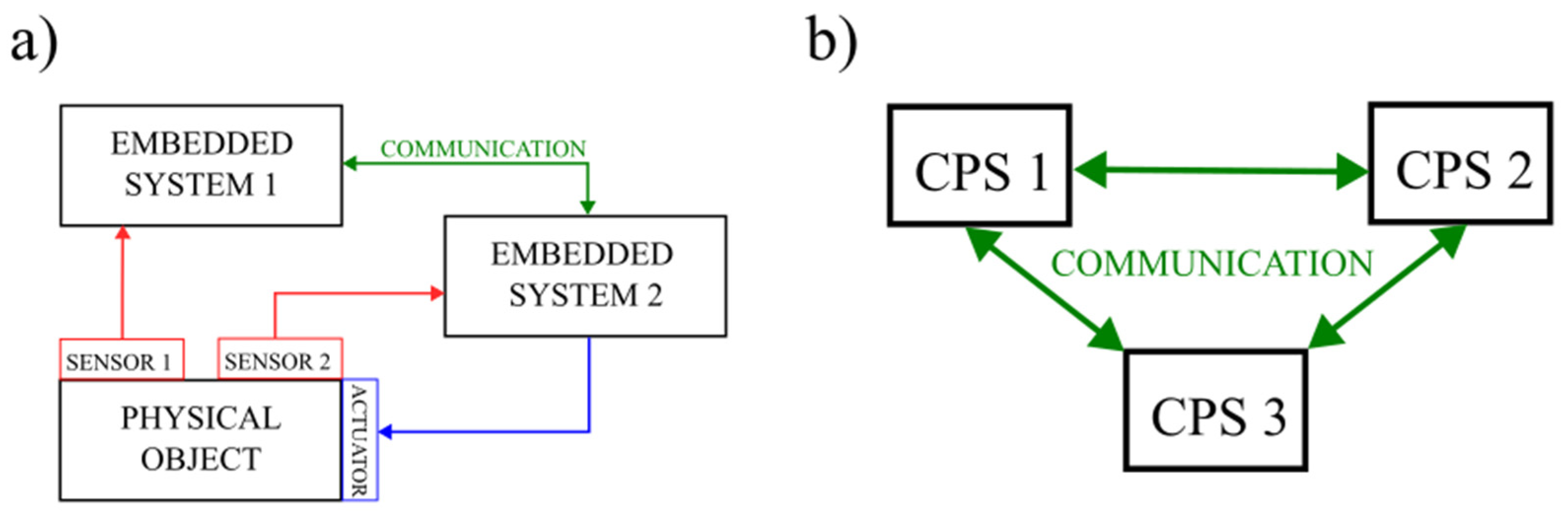
Figure 2.
(a) Structure of a CPS with an agent; (b) communication between three CPSs with agents.
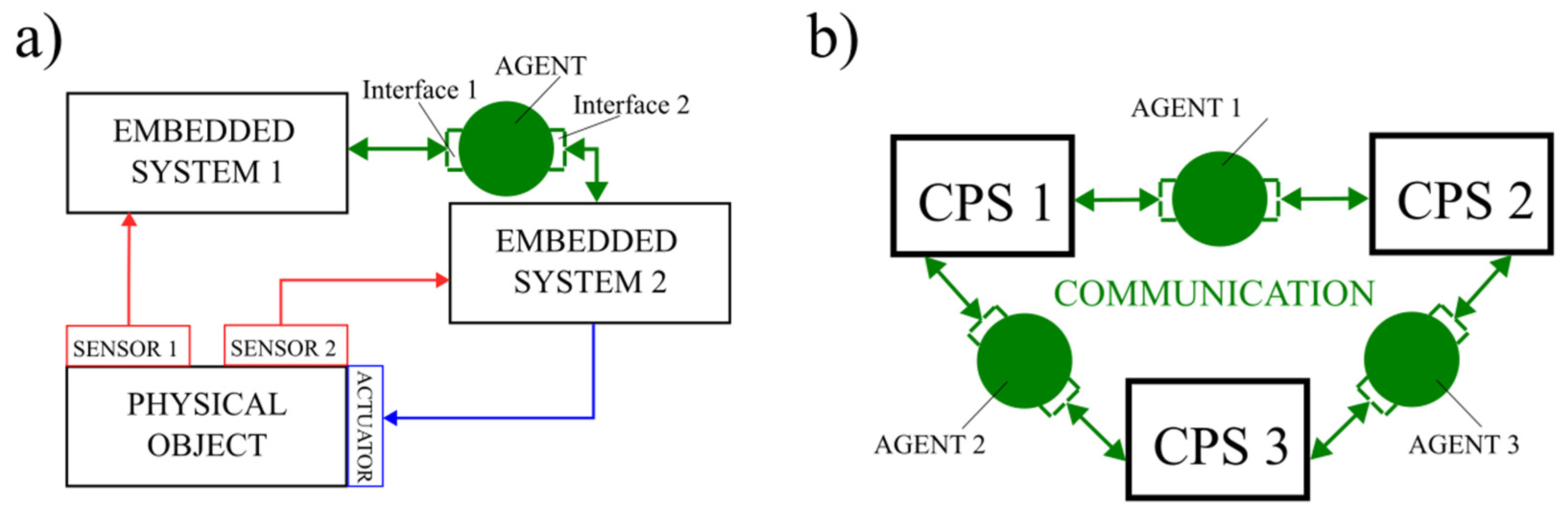
Figure 3.
Schematic diagram of the RoboDataLink.py program.
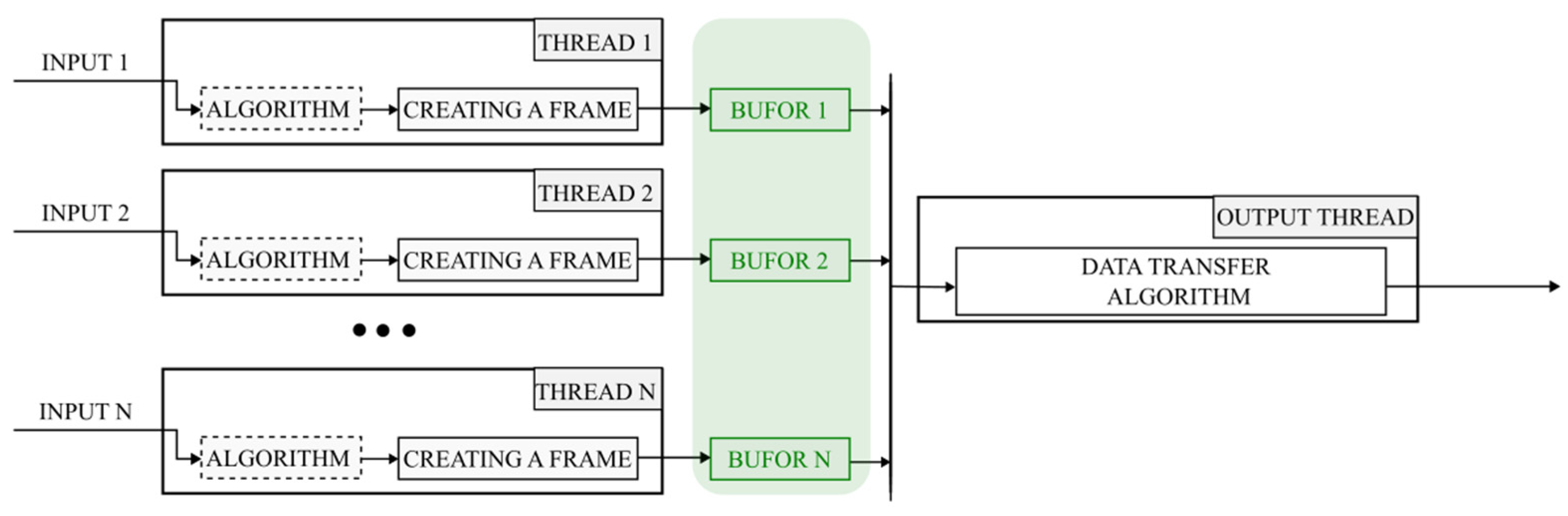
Figure 4.
Schematic of test bench.
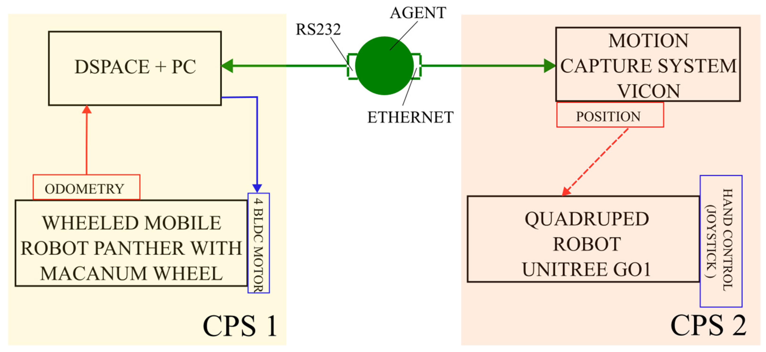
Figure 5.
MRK Husarion Panther with Mecanum wheels (a) and Unitree GO1 robot (b).
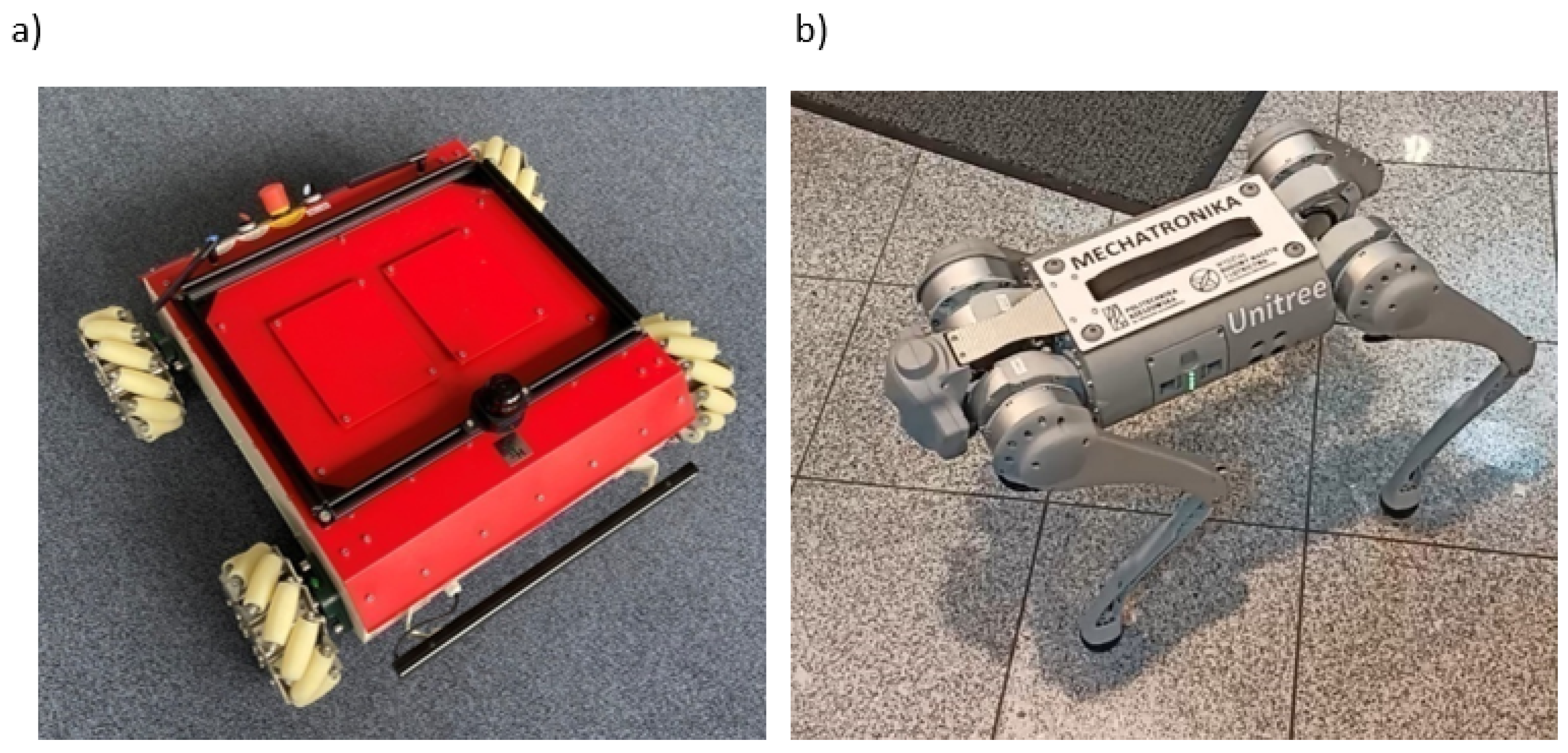
Figure 7.
The structure of RoboDataLink.py for the application under consideration; (b) the structure of the frame containing object position data from the motion capture system.
Figure 7.
The structure of RoboDataLink.py for the application under consideration; (b) the structure of the frame containing object position data from the motion capture system.
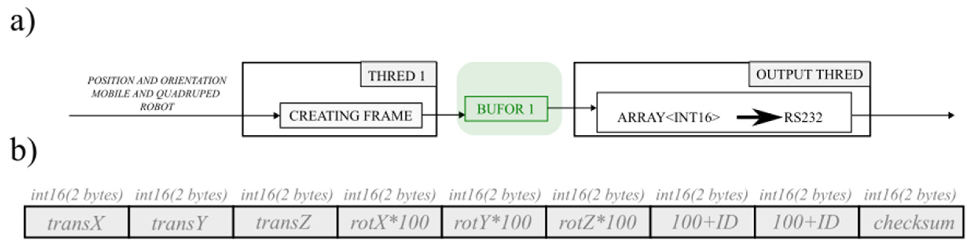
Figure 8.
Hierarchical control algorithm for a mobile robot.
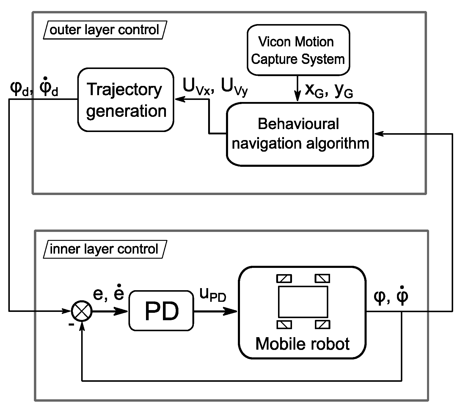
Figure 10.
Test results: a—position of the target () and mobile robot () relative to the x-axis, b—position of the target () and mobile robot () relative to the y-axis.
Figure 10.
Test results: a—position of the target () and mobile robot () relative to the x-axis, b—position of the target () and mobile robot () relative to the y-axis.
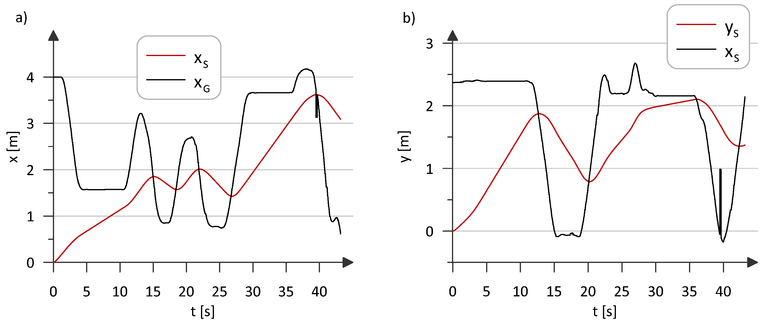
Figure 11.
The motion path of the characteristic point S belonging to the mobile robot: read from encoders (xy_encoder), read from the motion capture system (xy_motion_system).
Figure 11.
The motion path of the characteristic point S belonging to the mobile robot: read from encoders (xy_encoder), read from the motion capture system (xy_motion_system).
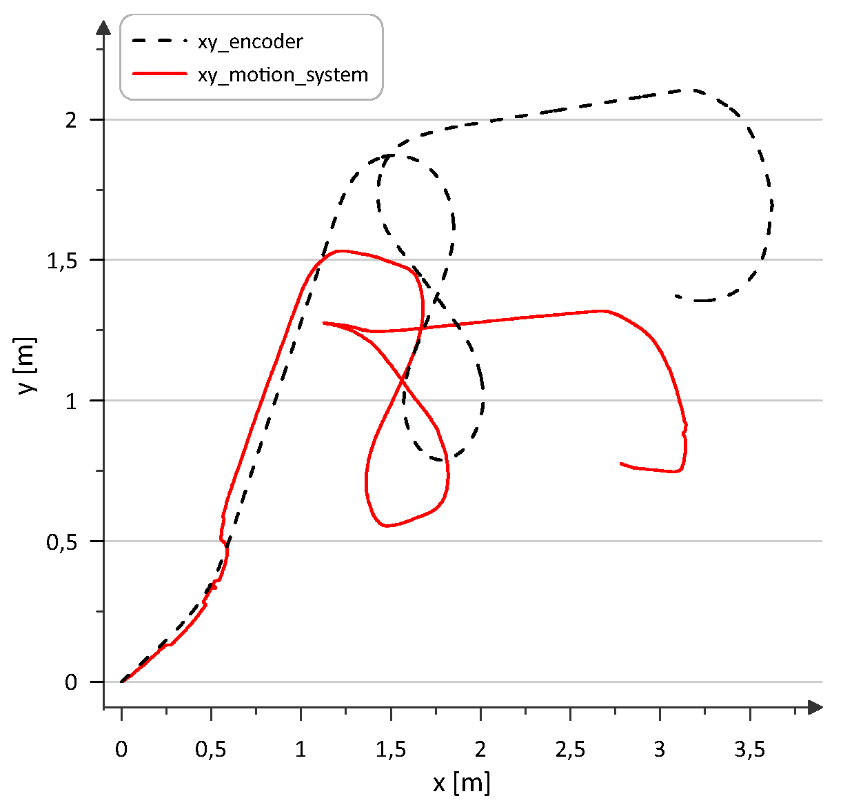
Figure 12.
Test results: a—distances between the position of the target and the position of the mobile robot: relative to the x-axis (), relative to the y-axis (), b—waveform of the robot speed control signal, c—waveforms of the generated angles of rotation of the Mecanum wheels, d—waveforms of the generated angular velocities of the Mecanum wheels.
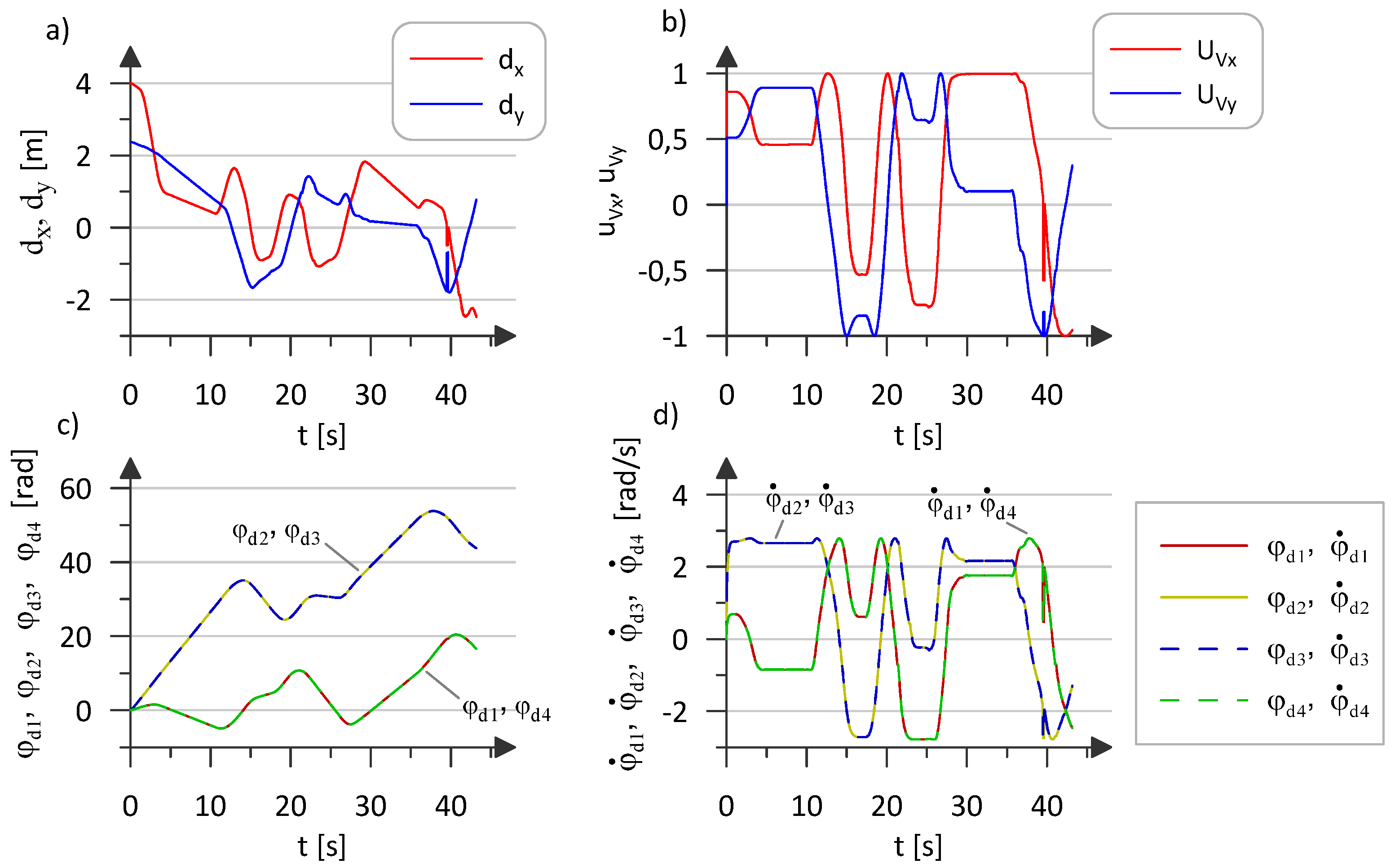
Figure 13.
Test results: a—waveforms of control signals generated in the inner layer, b—waveform of Mecanum wheel angle tracking errors, c—waveform of Mecanum wheel angular velocity tracking errors.
Figure 13.
Test results: a—waveforms of control signals generated in the inner layer, b—waveform of Mecanum wheel angle tracking errors, c—waveform of Mecanum wheel angular velocity tracking errors.

Disclaimer/Publisher’s Note: The statements, opinions and data contained in all publications are solely those of the individual author(s) and contributor(s) and not of MDPI and/or the editor(s). MDPI and/or the editor(s) disclaim responsibility for any injury to people or property resulting from any ideas, methods, instructions or products referred to in the content. |
© 2024 by the authors. Licensee MDPI, Basel, Switzerland. This article is an open access article distributed under the terms and conditions of the Creative Commons Attribution (CC BY) license (http://creativecommons.org/licenses/by/4.0/).
Copyright: This open access article is published under a Creative Commons CC BY 4.0 license, which permit the free download, distribution, and reuse, provided that the author and preprint are cited in any reuse.


