Submitted:
14 August 2024
Posted:
15 August 2024
Read the latest preprint version here
Abstract
Imitation learning, also known as programming by demonstration, has been shown to be a promising paradigm for intuitive robot programming by non-expert users. However, the classical kinesthetic approach with physical hand guidance suffers from generalizability across different robot types and is impractical for demonstrating tasks with long horizons. Visual imitation learning enables the recording of multi-step tasks as a single continuous video, allowing non-experts to demonstrate tasks naturally. Existing approaches typically require a large amount of data to develop end-to-end deep learning models that map raw pixels to robot actions. This paper explores the application of visual imitation learning from one-shot demonstration, significantly reducing the data requirements and simplifying the programming process. To achieve this target, a framework is proposed to map hand trajectories to the robot end-effector, consisting of four essential components: hand detection; object detection; segmentation of the trajectories into elemental skills; and learning the skills. Methods are developed for each component and evaluated on recorded videos to demonstrate the effectiveness of the proposed framework.
Keywords:
Visual imitation learning
; Robot
; One-shot demonstration
1. Introduction
Learning from demonstration is a framework that allows robots to learn to perform tasks from human demonstration of those tasks. Initially, the field focused on physical interaction, where humans directly guide robots, manipulating their arms and tools to perform specific tasks. This method is also called kinesthetic teaching [1,2]. One drawback of kinesthetic teaching is its dependence on the specific type of robot used. Transferring skills learned on one robotic platform, such as the Barrett WAM arm with seven axes, to another with different specifications, like a six-axis UR robot, can be complex. This complexity arises because the kinematic and dynamic properties of the robots may differ significantly. The differences affect how movements and skills are executed. Over time, the field has expanded to include observational learning, where robots learn from visual data [3]. It overcomes the challenges across different robotic platforms. This process employs visual inputs captured by cameras or other sensory systems to understand human-performed actions. In the end, the robot program are generated based on the interpretation of the recordings. Furthermore, visual imitation learning provides more contextual information compared to kinesthetic teaching. Visual data captures not only the motion but also the environment in which the task is performed. This rich contextual information enables the robot to better understand the task and adapt its actions accordingly.
Based on the learning results, the outcomes of visual imitation learning can be categorized into three levels:
- Skill Level: This involves learning specific movements or actions that a robot must perform. Skills are the fundamental building blocks, such as grasping an object.
- Task Level: At this level, the robot learns to combine multiple skills to perform a more complex activity.
- Goal Level: This highest level involves understanding the overall objective of tasks.
At the skill level, the focus is on the acquisition of individual motor skills or actions for basic manipulations. Finn et al. presented a visual imitation learning method that enables a robot to learn new skills such as push and place from raw pixel input [4]. The policy is represented by Convolutional Neural Networks (CNN). The policy observation includes both the RGB image and the robot’s joint angles and end-effector pose. A policy is learned to map observations to robot actions. The approach integrates meta-learning with imitation learning, allowing a robot to reuse experience and quickly learn new skills from a single demonstration. This is achieved through a two-level learning process: the inner loop makes task-specific adjustments, while the outer loop updates meta-parameters across tasks. However, the two-level training process is complex and the learned model is adapting poorly to environment changes. Xin et al. developed a so-called IRMT-Net to predict the interaction region and motion trajectory from RGB-D images [5]. The input of the developed model consist of motion trajectories, motion category and cropped object images. To generate motion trajectory from RGB-D images, the hand detection method proposed by Shan et al. [6] is applied to extract bounding box from each RGB frame. The center coordinate of the bounding box and its depth value are taken as 3D hand coordinates. Faster-RCNN [7] is used to detect objects. The cropped image for the detected object is obtained based on the bounding box with the highest detection score. To evaluate the proposed approach, a dataset is created by labeling the motion trajectories for videos in the Epic-kitchens dataset [8] with 9236 videos. In the end, skills such as pull open drawer and take cup in kitchen scenarios are learned. The annotated dataset contributes to the further development of visual imitation learning for kitchen scenarios. Wen et al. introduced a method for learning task trajectories using a single demonstration video, captured by a statically mounted Photoneo 3D camera [9]. This camera records at 10 Hz. It provides gray-scale and depth images, allowing for detailed observation of the working environment. The method involves tracking target objects to generate trajectories, which demonstrated effective performance. A key factor contributing to the success of this approach is the use of relatively large objects, which minimizes occlusion by the human hand during the demonstration.
At the task level, the focus is on understanding sequences of actions. The raw data are typically hand trajectories captured by cameras or other types of motion sensors. Qiu et al. presented a system with observing human demonstrations by an ASUS RGB-D camera [10]. During demonstration, a human worker performs an object handling task wearing a colored hand glove. This hand glove improves the accuracy and robustness for hand detection. The hand pose is estimated based on a deep learning model trained by 3D input data [11]. The human demonstration is segmented by Hidden Markov Models (HMMs) into motion primitives called skills. They include pick up, place and locate. The skills are then represented by Dynamic Movement Primitive (DMP) [12], which allows the generalization to new goal positions. Notably, there are no general consensus for defining the semantic of skills in the existing works. Qiu et al. consider pick up, place and locate as skills [10]. However, Kyrarini et al. define them as start arm moving, object grasp, object release [13]. This discrepancy in definitions presents a challenge when comparing the performance of different approaches. The availability of visual context allows for the consideration of spatial relationships between task-relevant objects in addition to the understanding of action sequences. Ding et al. developed a learning strategy for pick & place tasks, in which the continuous human hand movement are tracked by Kinect V2 [14]. The human hand centroid trajectory in XYZ positions are first segmented into the approach-pick phase, the arrive-place phase and the withdraw phase by calculating the hand velocities. GMM-GMR [15] is then applied to generate optimal demonstration trajectory. DMPs are then learned for trajectory generalization. To understand spatial relationships, the sequence of pre-action and post-action images are recorded and processed. Classical computer vision algorithms are applied to match features to extract pixel centers of relevant objects. During execution, the algorithm find the best match between the recorded data and the current scene. The resulted task model is a combination of the learned trajectory and the spatial configuration. This work illustrates the potential for the integration of additional semantics through the application of computer vision algorithms in the field of visual imitation learning.
At the goal level, the system observes demonstrations with the aim of identifying the ultimate objectives of tasks rather than the exact procedures used. The key is to infer the reason behind actions, allowing the robot to modify its approach based on its capabilities or the environmental conditions. Zeng et al. proposed an approach to enable robots to understand and execute tasks by interpreting the goals from demonstrations provided by the users [16]. The initial and goal scene are represented by RGB-D images. A method called Discriminatively-Informed Generative Estimation of Scenes and Transforms (DIGEST) was developed to generate scene graph from demonstrated images. The first step in the DIGEST method involves detecting bounding boxes in the RGB images. Once objects are detected, their pose is estimated using the depth information from the RGB-D images and existing object mesh models. The final step is to generate a scene graph. This graph represents the spatial and relational structure of the scene. It is built using inter-object relations such as exist, clear, in, and on by calculating the object poses. Given the observation of the goal state of the world, the robot estimates the goal scene graph, and stores the desired inter-object relations by PDDL [17]. It is a formal language used for expressing planning problems and domains. The task planner gives a sequence of high-level pick & place actions. To pick an object, the robot receives a number of pre-computed grasping positions for the object, and uses Moveit!1 to determine which of these positions can generate a collision-free path. The learned task concepts are reusable for other robots. However, a new scene should be demonstrated with slightly different spatial relation.
In conclusion, visual imitation learning leverages the latest advancements in computer vision and machine learning to enhance robot programming at multiple levels. These levels include the execution of basic skills, the understanding of complex task sequences, and the achievement of task goals. The task models learned by this approach are independent of the robot’s kinematic and dynamic parameters, so they can be applied to different robots. Challenges at these levels include the need for precise goal definition, the variability of environmental conditions, and the availability of training data. The variability of environmental conditions include factors such as lighting changes and object variability.
A framework is proposed in this work to address two of the three challenges: the variability of environmental conditions and the availability of training data in specific domain. The framework includes hand detection, object detection, motion segmentation and motion learning. The goal is to realize one-shot demonstration for multi-step pick & place tasks. This is realized by mapping the hand trajectories to robot’s end-effector. Tracking the hand is more appropriate as small objects may be occluded and not visible. Specifically, the following questions will be discussed:
- How can existing frameworks effectively detect human hand movements from RGB images?
- How can the object be detected without manually collecting and annotating data?
- How can the task-level trajectories be segmented into skills?
- How can the segmented skills be represented to be adaptable to new situations?
2. Materials and Methods
2.1. Task Model Representation
To learn the multi-step pick & place tasks, a task model consisting of four layers is developed and illustrated in Figure 1. It listed from high-level task plan to low-level position. The task plan is a sequence of actions to complete the task. Each action as a parameter of an object. A pick action refers to the act of selecting and lifting an object from a particular location. It involves grasping the object to obtain control over it. To apply the learned task in different situations mentioned above, the pick action is further divided into Reach and Grasp skills. Reach is represented by motion from random start to grasp position. Grasp is considered as a discrete event, which occurs in single timestamp. It represents the moment when robot’s end-effector successfully makes contact with the object and securely holds it. The place action is divided into Move and Release skills. Move is represented by motion from grasp to release positions with the moving object. Release is also considered as a discrete event. It involves opening the gripper from the end effector. The skills are extracted from the demonstration video. The grasp and release position of object can be estimated from visual information. This structured task model helps the robot to effectively understand and execute the tasks in dynamic environments.
2.2. Hand Detection
There are several trained models and frameworks available for hand detection. In this work, two common approaches used in the context of visual imitation learning, one from the Bbox-based approaches and one from the keypoints-based approach are selected to evaluate hand movements. As discussed in the first section, Xin et al. applied a pre-trained Bbox-based model to learn hand motion trajectories with promising results [5]. The model was proposed by Shan et al. to understand hand and hand-object interaction [6]. The system was built on top of a popular object detection system, Faster-RCNN [18]. The model has a two-stage architecture, where the first stage proposes regions and the second stage classifies and refines the bounding boxes. The models were trained on the datasets proposed in the same publication, the 100DOH dataset and the 100K frames. The 100DOH is a large video dataset containing hands and hand-object interactions. They are K Youtube videos from 11 categories with nearly 131 days of footage of everyday interaction. To detect hand on single image, the authors created a new 100K frame-level dataset, which consists of 99,899 frames extracted from the videos in 100DOH and VLOG Dataset [19]. In total, there are 189,426 annotated bounding boxes for hand. Two models trained on 100K and 100K+ego are provided by the authors for hand detection. The 100K+ego consists of K frame subset of egocentric data from [20,21,22]. Both models achieve approximately 90% average precision.
Another detection method is based on keypoints, which is an open-source framework developed by Google called MediaPipe [23]. It provides a pipeline for hand detection. The output of the hand detector are 21 3D hand-knuckle coordinates inside of the detected hand regions. The examples are demonstrated in Figure 2a,b. The representation of each keypoint is composed of x-, y- and z- coordinate, where x and y are pixel coordinates on image and z is the distance to the wrist as origin. A hand trajectory can be created from either method using the center of the hand position.
The two methods will be evaluated in the third section.
2.3. Object Detection
As discussed in the first section, object detection in visual imitation learning is crucial for understanding task environments. Thanks to the availability of large datasets, various model architectures have been developed and shown to continuously improvement performance. Most of available datasets are labeled with regular bounding boxes for everyday objects. They serve as benchmarks for comparing different model architectures. Some well known datasets are ImageNet [24], Pascal VOC [25] and COCO [26]. They provide raw images, its annotations and standardized evaluation protocols. COCO is currently the standard benchmarking dataset for the object detection community. The latest release of COCO 2017 consists of a total of 123,287 images and 896,782 objects, across its validation datasets. Additionally, the testing dataset comprises 40,670 images. They cover 80 object categories, which include everyday objects such as person, bicycle, and car, as well as household items like chair, couch, and dining table. The annotation include the bounding box coordinates, the category level, and other optional attributes. More detailed information about the COCO dataset can be found on the official website2. The bounding boxes provided in COCO are rectangular boxes aligned with the image exes that enclose the object. They do not account for the object’s rotation. However, the orientation is essential for application scenarios such as understanding aerial images. Dataset of Object deTection in Aerial images (DOTA) [27] is a large-scale dataset for the application of aerial images. The DOTA dataset consists of a total of 1,793,658 object instances that are annotated with oriented bounding box (OBB) annotations. The illustration of the annotations is shown in Figure 3, where refers to the rotation of the rectangular box with respect the image axis. The object instances in DOTA belong to 18 different categories, which include objects like planes, ships, and basketball courts. The OBB approach is followed in this work, which allows for improved accuracy and better object differentiation.
As discussed above, existing datasets primarily cover everyday objects. To develop object detection models for a specific task in manufacturing scenarios, it is necessary to generate a specific set of objects. The data generation process involves capturing images and manually annotating the objects of interest, which is time-consuming. CAD files are usually available in manufacturing scenarios. Synthetic training data can be generated using CAD data and has gained popularity in recent years due to its advantages in providing accurately labeled datasets at a lower cost [28]. In this work, an approach using rendered images in Blender to generate the dataset is used. The details of the synthetic data generation are discussed below.
2.3.1. Data Generation
Photorealistic images are created or rendered to closely resemble real-life objects or scenes. Hodaň et al. developed an approach to synthesize photorealistic images of 3D models, which are used to train a convolutional neural network for detecting the objects in real images [29]. The approach is implemented in BlenderProc, which is an open source pipeline to render the images [30]. The pipeline is a Blender extension with Python API with various examples. The image synthesis approach3 for generating LineMOD dataset in BOP challenge is followed in this work. In this approach, objects are arranged inside an empty room. A random photorealistic material from the CC0 Textures4 library is assigned to the walls of the room, and light with a random strength and color is emitted from the room ceiling and from a randomly positioned point light source. Realistic object poses are achieved by dropping objects on the ground plane using PyBullet physics engine integrated in Blender. In the pipeline, both the images and their corresponding annotations are produced simultaneously and automatically. The annotations are generated in OBB format to preserve the orientation of the objects. Examples of photorealistic images of 6 CAD models are shown in Figure 4, which are grayBox, blueBox, cuboid, parallelogram, star and octagon.
YOLOv8 is utilized in this work to detect object of interests due to the availability of pre-trained models for OBB detection and its software framework. The model utilizes a convolutional neural network that can be divided into two main parts: backbone and detection head. The head of YOLOv8 consists of multiple convolutional layers followed by a series of fully connected layers. These layers are responsible for predicting the oriented bounding boxes and class probabilities for the objects detected in the image. During fine-tuning, the parameters from the model backbone are used to initialize the model, the detection head are initialized with number of classes for the new task. The fine-tuning of the YOLOv8 model with the photorealistic images and the validation on real images will be discussed in the third section.
2.4. Mapping Motion from a Human Hand to a Robot End-Effector
This section focuses on mapping motion from a human hand to a robot end-effector. Figure 5 illustrates the mapping concept. The framework starts by generating hand and object trajectories from continuous frame-by-frame hand and object detection. These trajectories are then segmented based on the interaction of the hand and object and the object state. The resulting hand motion segments reach and move are represented as skills with DMPs. These representations are stored in the task model to reproduce the task.
2.4.1. Trajectory Generation for the Human Hand and the Objects
A RGB-D camera is required to record the visual demonstration. Hand and object detection are performed on the RGB frames. The detected results are bounding boxes at pixel coordinates. The corresponding depth values can be read from the depth frame. The Equation 1 shows the process. The center of detected bounding boxes from RGB images for the human hand and objects are and . The responding depth value can be identified from depth image. Similar as RGB image, the depth image is represented by a two-dimensional matrix, = (y, x), the coordinate (x, y) corresponds to the column and row indices, respectively. The depth value can be identified from depth image (, ). The resulted sequence of = {, , } are hand and object trajectories in pixel coordinates as shown in Figure 6. In the next step, the position are transformed to real world coordinates with camera as origin. In the equation, and describe the focal length of the image, and the and describe the pixel coordinates of the principal point. They are camera intrinsic parameters to describe the internal characteristics of the camera.
According to Ghidoni [31], several technologies are available for estimating depth information: stereoscopy, infrared light and LiDAR. A stereoscopic camera captures two images simultaneously from different angles to determine distance. Infrared and LiDAR technologies work on a similar principle. They use a light source and a receiver to measure the time it takes the light to reach the sensor. Both of these technologies are referred to as ToF sensors. Each technique can be affected by lighting conditions and the texture of objects, and have invalid depth values. To overcome bad depth value, an additional estimated depth map from the color image is used in this work. It uses the global-local path networks model for monocular depth estimation [32]. The model is made available by Hugging Face5. In case the depth value is unavailable in aligned depth frame from camera, it will be estimated from color frame using the pre-trained model from Hugging Face. The transformation from pixel coordinates to camera frame is also performed using Equation 1.
By repeating the above mentioned process for each pair of RGB and depth frames, the hand and object trajectories can be generated in 3D space. Normally, the object detection accuracy cannot reach . If the hand and the object of interest cannot be detected in some frames, the last valid detection is propagated to the next frame. The generated hand and object trajectories can be represented as = (, ⋯, ⋯, ).
2.4.2. Motion Representation for a Robot’s End-Effector
To map hand motions to the robot’s end-effector, the hand trajectories are segmented into smaller components which allows adapting hand to end-effector position, as shown in Figure 1 in Section 2.1. The skills representation for the robot’s end-effector during the pick-and-place process is summarized in Table 1, where denotes the position of the end-effector at timestamp t. The action of picking up an object involves the reach and grasp skills. The reach skill describes the motion of the end-effector from a starting point to the grasping position. Once the end-effector reaches the object, the grasp occurs at the next timestamp. After grasping the object, the move skill is used to transport the object to the desired location. Unlike the separate motions of moving and positioning in human hands, transporting an object with a robot is considered a continuous motion. Upon arriving at the desired position, the release skill is triggered to relinquish control of the object.
In the practice of robot programming, after defining the grasp and release positions, additional pre- and post-motion segments are created to ensure a controlled grasp and release. The pre-grasp involves approaching the object at reduced speed and corrected orientation. Once the robot reaches the pre-grasp pose, it performs the grasp action to securely hold the object. After successfully grasping the object, the robot moves back to post-grasp pose with the reversed approach trajectory to avoid collision with the environment. The pre- and post-grasp pose are typically the same, ensuring consistency in the robot’s pose. Once in the pose-grasp pose, the robot transitions to the move skill to transport the object to the desired place position. The pre-release involves preparing the robot and the object for release. It includes adjusting the robot’s pose to ensure a controlled release. The speed of pre-release and pose-release is usually reduced compared to the transport motion. After releasing the object, the robot returns to post-release pose to start the next movements. Similar to the pre- and pose-grasp poses, the pre- and post-release poses are typically the same for consistency, as shown in Figure 7. In summary, to map a human hand trajectory to a robot’s end effector, the hand trajectories are first segemented in to reach, grasp, move and release, and then augmented with pre-grasp, post-grasp, pre-release and post-release. The orientation of the objects is determined during the pre-grasp and pre-release phases and remains constant throughout the post-grasp and post-release phases.
2.4.3. Trajectory Segmentation
This subsection explains how hand trajectories are segmented into smaller elements to represent the skills of Reach, Grasp, Move, and Release. This is accomplished by identifying the timestamps for grasping and releasing. The input data consists of the hand and object trajectories generated in section 2.4.1. Segmenting hand trajectories directly can be a challenging task. Because hand movements often transition smoothly from one phase to another without clear and distinct boundaries. It is therefore difficult to identify where one segment ends and another begins. To address this issue, an approach is proposed that leverages the status of hand-object interaction and object status.
As discussed in section 2.4.1, before segmenting the trajectories, missing values caused by detection failure are filled by propagating the last valid value to the next one. Then, a Kalman filter is applied to reduce noise. The hand trajectories are first segmented into pick and place cycles for each object by identifying the release timestamps. They are achieved by segmenting the object trajectories by Gaussian Mixture Model (GMM). It is a statistical model that represents a probability distribution between input x and output y variables as a weighted sum of Gaussian distributions.
where each Gaussian component has prior probability = , mean , and covariance matrix . GMM parameters = are learned from training data using the expectation-maximization. It can be utilized for motion segmentation by modeling the distribution of trajectories over time. In a pick & place task, the object trajectory can be divided into three distinct parts, the static state before picking, the moving state, and the static state after placing. The first timestamp in the state after placing indicating the release of the hand. In this work, the object trajectories are segmented by the GMM model with K = 3 and = = {}.
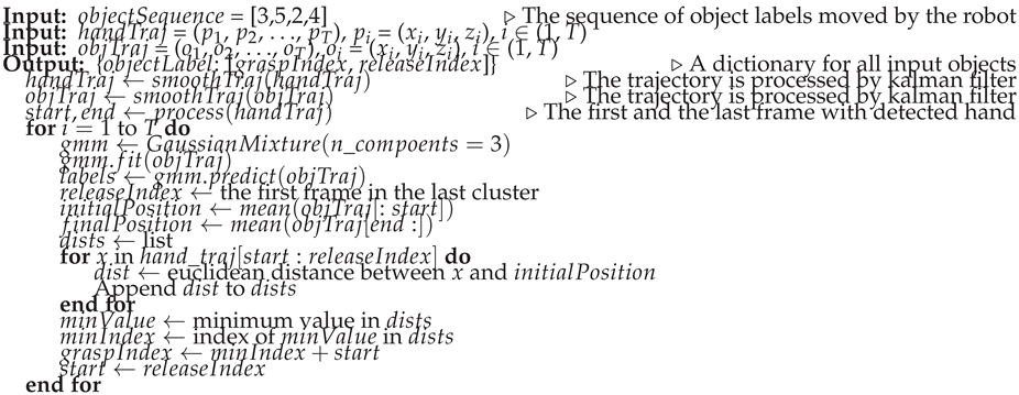
In the second step, the grasp timestamps are used to segment the pick and place motion into reach and move. When a human hand and other objects are present in the same visual frame, occlusion can occur, which means the hand might partially or fully block the view of the object. This can result in inaccurate object trajectories that do not accurately represent the grasping process. However, the object can be correctly detected at the beginning and end of the demonstration, where the human demonstration has finished or not yet started. The grasp timestamp is then determined by calculating the shortest distance between the hand and the object’s initial position. The results are grasp and release index in the time sequence for each object. The resulted sequence symbols for three objects can be represented as [Reach(), Grasp(), Move(), Release(), Reach(), Grasp(), Move(), Release(), Reach(), Grasp(), Move(), Release()].
The segmentation approach is summarized in Algorithm 1.
| Algorithm 1 Segmentation hand trajectories |
 |
2.4.4. Trajectory Learning & Generation
DMP can learn from a single demonstration and adapt to new start and goal positions [13]. They are therefore used to model goal-directed behaviors. The resulting reach and move segments are represented by DMPs, which are formalized as stable nonlinear attractor systems [12]. There are many variations of DMPs. As summarized by Fabisch [33], they have in common that
- they have an internal time variable (phase), which is defined by a so-called canonical system,
- they can be adapted by tuning the weights of a forcing term and
- a transformation system generates goal-directed accelerations.
The formulation of DMPs can be found in [33,34,35]. The choice of coordinates for representing a model can make a big difference in how the generalization of the dynamics systems appears [34]. The DMP are represented in the camera frame in both the trajectory learning and generation processes. Figure 8 illustration the steps for generating robot end-effector trajectories using DMP. To generate the trajectory for reach, the process begins with defining the current position of the end-effector and aims to reach the pre-grasp position. The learned DMPs from the hand trajectories are updated based on defined initial and goal position of the target object. This process generates a smooth trajectory for the specified duration. Similarly, DMP for move is updated by defining the post-grasp position and the pre-release position. The adaptability of DMP allows for updating with new initial and goal position, ensuring controlled movements.
3. Results
3.1. Experimental Setup
The goal of this work is to extract the required information from a single video. To avoid any potential bias or singular occurrences, five sets of instructions and their corresponding videos were recorded and evaluated. Figure 9 (a) illustrates the experimental setup to record the videos. The Intel® RealSenseTM L515 3D camera is mounted on the robot to record the demonstration process. The camera is positioned to capture the task environment and hand movements. The task environment is shown in Figure 9 (b). As a LiDAR camera, it projects an infrared laser at 860 nm wavelength as an active light source. 3D data is obtained by evaluating the time required for the projected signal to bounce off the objects in the scene and come back to the camera [36]. The frame rate is 30 frames per second (FPS). The videos were recorded using Intel RealSense Viewer and saved as bag files, which can be extracted as sequence of color and depth images. The size of color images recorded by the L515 is 1280×720 and the size of depth image is 640×480. The depth frame is re-scaled and aligned6 to color frame, such that the depth value can be read by pixel coordinate of color image.
Multiple camera positions were used to evaluate the robustness and effectiveness of the proposed approaches from different angles and perspectives. The videos feature the same four pick & place tasks, which involve transporting a cuboid, star, parallelogram, and octagon from a blue box to a gray box. At the beginning and end of the recording, the task environment was observed without the presence of hands, ensuring a clear view of the working environment for accurate analysis of the conditions before and after the manipulation was performed. The task was performed with only one hand.
3.2. Evaluation of Hand Detection Methods
In section 2.2, two methods for hand detection are discussed. The first method is the bounding box-based approach developed by Shan et al. [6], which was trained with the Faster-RCNN model. The second method is the key points-based approach from Google, known as MediaPipe. Both methods were applied to the RGB image sequences. After detection, the results were further processed by transforming the hand locations into Cartesian coordinates in the camera’s coordinate system. This transformation leverages the depth value of the center point of the detected hand, which is crucial for accurately determining the hand’s position in three-dimensional space. This step enables the generation of hand trajectories.
The models provided by Shan et al. [6] are available online7 as open source. The detection process is integrated into Detectron28, which is a framework for computer vision tasks such as object detection and instance segmentation. The model trained on 100K + ego was used to run the test. The score threshold for filtering out low-confidence detection was set at . Any model output below this threshold is considered as invalid. A low threshold means that the model accepts detections with lower confidence levels, which can significantly increase the number of false positives. The performance of the both methods are evaluated on the five recorded videos, which consists of 3601 images in total, where hand are visible in 2631 images. The results are summarized in Table 2. The percentages in the table represent the proportion of images where the methods successfully detected hands when hands are present. It was observed that the model failed when the hand was too small in the image, an example is shown in Figure 10.
The key points-base method MediaPipe9 is an open-source framework, which is available for use with different programming languages and devices. The hand landmarks detection solution in Python within this framework is used to evaluate the performance. The parameter static image mode was set to True and the maximum number of hands was set to 1. The result in Table 2 show that the Faster-RCNN is generally more reliable for hand detection tasks than MediaPipe.
The hand trajectories were computed using the detection results from Faster-RCNN because it has better performance. The approach was presented in section 2.4.1. An example of a hand trajectory is shown in Figure 11. From this graph, the hand movement is most variable along the z-axis (depth), as indicated by the green line. This is due to the hand moving towards and away from the camera for the multi-step pick & place task.
3.3. Training and Evaluation the Object Detection Model
When it comes to detecting objects that are not as commonly modeled as hands, where pre-trained models and datasets are readily available, it is typically necessary to generate a custom dataset for training. A total of 18,750 photorealistic images with were generated using the approach discussed in section 2.3.1 to train the YOLOv8 model for the OBB detection task. Out of these, 15,000 images are used for the training set, and 3750 images are allocated for the validation set to evaluate the performance of the model. Transfer learning approach is used with the pre-trained model YOLOv8 from Ultralytics10. During training, the number of epochs was set to 20. The IoU was set as . The learning rate was set to the default value of , as this has been demonstrated to be a value for transfer learning tasks.
The Table 3 presents the object detection results for the validation set consisting of 3,750 images with a total of 21,821 instances across various classes. The overall precision and recall for detecting all classes are and respectively, with a mAP at IoU threshold of and mAP at 50-95% IoU of . Each class, including GrayBox, BlueBox, Parallelogram, Cuboid, Octagon, and Star, has a high precision and recall, ranging from to and to respectively. The mAP50 for these classes varies slightly, between and , while the mAP50-95 ranges from to . The Star class has the highest mAP50-95 at and shares the highest precision and recall with the Octagon class at . The Cuboid class shows a slightly lower precision compared to others at . Overall, the results indicate a high level of accuracy in the object detection task for this validation set.
The object detection model trained on photorealistic images was evaluated on real-world images to assess its performance. Three representative images with the detection results are presented in Figure 12. In these images, the model is able to identify and localize the object of interest within the scene. However, the occlusion and the presence of a human hand show poor performance.
To evaluate the performance of the domain adaption. images without the presence of a human hand were considered. 971 images from the 5 recorded videos are extracted. The Table 4 presents performance for different classes, including the number of images, instances and accuracy. The model achieves impressive performance on the entire dataset, with accuracy indicating that all detected instances are correct. The recall of of suggests that the model is capturing a significant fraction of the actual instances. The mAP50 score of indicates a high average precision at a threshold of 50. The model performs differently for each class. For instance, the GrayBox and BlueBox class exhibit lower recall values of approximately due to object occlusion within the box. The detection results can be rectified by utilizing the information that the both objects remain stationary during the demonstration. The mAP50-95 score measures the average precision at a higher threshold range (50-95). This score is useful for evaluating the model’s performance on challenging instances or in scenarios where higher precision is required. It is worth noting that the mAP50-95 scores are relatively lower compared to the mAP50 scores, indicating potential for improvement in detecting instances within this threshold range.
3.4. Evaluation of Depth Value Quality
Depth value is essential to generate the hand and the objects trajectories in Cartesian coordinates. Chen et al. discusses the common challenge of motion blur in depth sensing technology, particularly in dynamic movements with ToF sensors [37] . Depth is calculated by measuring the time it takes for a light signal to travel to the object and back to the sensor. However, movement of objects can distort the timing measurement, resulting in inaccuracies. The experimental results of calculating the depth value of hand and object show the same pattern, where the depth value of hand trajectories is generally worse than that of object trajectories. Specifically, the study notes that valid depth values for hand trajectories fall below , whereas for objects, they exceed . In case of invalid depth value, the depth is estimated using the method discussed in section 2.4.1. The difference between the depth value estimated by the pre-trained deep learning model and the valid depth value from the camera is less than 1cm. This evaluation demonstrates the necessity of using depth estimation techniques to ensure accurate trajectory generation and highlights the performance of the applied depth estimation method.
3.5. Evaluation of the Proposed Segmentation Approach
The hand trajectories from the recorded videos were then segmented using the Algorithm 1. They are calculated by the object trajectories and the distance between the hand and the target object. An object trajectory is outlined in Figure 13. Each color represents a component generated by GMM. The trajectories were taken as correct segmented by inspecting the image at the identified timestamps for grasp and release. This method of verification ensures that the segmentation aligns with the actual moments when the object is manipulated. The approach was successful in identifying the grasp and release events for all target objects in the video with high accuracy.
3.6. Evaluation of the Motion Learning Approach
As discussed in section 2.4.2, the segmented trajectories are modeled by DMP, which represent reach and move skills. As shown in Figure 11, the hand trajectories have irregularities, which illustrates the necessity for DMP to smooth these trajectories. Moreover, the DMP should be capable of generalizing to new start and target positions. The implementation of Fabisch [33] in Python was used to learn the DMPs11. Figure 14 illustrates the learned and updated DMP for representing the skill reach with regulation coefficient = 0. The number of functions in Equation ?? was set to N = 20. The “Demonstration” curve represents a segmented trajectory of a hand motion from the starting point to a pre-grasp position. The “Reproduction” curve shows how the DMP was learned to imitate the original hand motion by attempting to follow the demonstrated trajectory. To enhance the manipulation accuracy, the DMP was adapted to object’s position “New Start” and “New Goal”. Since = 0, the noise and irregularities in the hand trajectory are encoded in the DMP, the phase approaching the goal in the figure shows the description. Figure 15 illustrates the improved DMP with = , the “Reproduction” and “Adaptation” curves show that the influence of noise from the demonstration trajectory is reduced. Figure 16 shows the learned and updated DMP for representing the move. In summary, the learned DMP are able to adapt learned behaviors to new situations while preserving the details of the original demonstration.
3.7. Evaluation on Robot in Simulation
The learned tasks are successfully executed within the ROS environment, as shown in Figure 17. Note that the approach proposed in this work are designed to be independent of the specific robot model, the UR5 model was chosen for its common usage in research. The implementation demonstrates the effectiveness of the semantic programming system. It can effectively learn the human actions and adapt to new object positions.
4. Discussion
This work proposes a framework that enables robots to learn from a single visual demonstration, focusing on multi-step pick-and-place tasks. The framework comprises four components: 1) hand detection; 2) object detection; 3) trajectory segmentation; and 4) skills learning.
For hand detection, two pre-trained models were identified and evaluated, with the Faster-RCNN model [6] demonstrating superior performance. Consequently, this approach is applied to the recorded videos to calculate the hand trajectories in the camera frame.
For object detection, the pre-trained YOLOv8 model was used. The availability of training data is essential, and the Blenderproc framework is utilized to generate photorealistic training images and annotations from CAD files. The pre-trained YOLOv8 model was fine-tuned on these photorealistic images. The model was then validated on real images, showing promising detection results. However, improvements are necessary for detecting difficult objects. To train the model for new objects, this pipeline can be replicated: generating photorealistic training data with Blenderproc, fine-tuning the YOLOv8 model on this data, and validating its performance on real images.
An algorithm is proposed to segment the multi-step pick-and-place tasks into the skills reach, grasp, move, and release. Initially, the trajectories are segmented to handle different objects, and subsequently, the elemental skills are identified. The evaluation demonstrates the effectiveness of this approach, confirming its capability to accurately decompose and execute the multi-step tasks.
To represent the reach and move skills, DMPs are used, as they are adaptable to new initial and goal positions of the target object. The evaluation shows the effectiveness of this method, with the robot successfully executing the learned skills with new start and goal positions.
The framework’s modular design allows for the individual improvement and updating of each component without effecting the entire system. It can be improved to include more component such as spatial reasoning. Furthermore, the fine-tuning process for the YOLOv8 model can be improved by incorporating more diverse and challenging training data, especially for objects that are difficult to detect.
Author Contributions
Conceptualization, Shuang Lu; methodology, Shuang Lu; software, Shuang Lu; validation, Shuang Lu; writing—original draft preparation, Shuang Lu; writing—review and editing, Christian Härdtlein, Johaness Schilp; visualization, Shuang Lu; supervision, Johaness Schilp; All authors have read and agreed to the published version of the manuscript.
Funding
This research was conducted within the project MeMoRob (AKZ: DIK0358/01) funded by the Bavarian Ministry of Economic Affairs, Regional Development and Energy (StMWi). The authors would like to thank the StMWi for the financial support.
Informed Consent Statement
Not applicable
Data Availability Statement
The data is available at https://drive.google.com/drive/folders/11LpzuVkabRRSv2kR7raaqmaqvvZ52s05?usp=sharing.
Acknowledgments
We would like to extend our gratitude to our colleagues at Fraunhofer IGCV, Christian Hädrtlein and Julian Glaß, for providing the CAD files and the objects used in the experiments.
Conflicts of Interest
The authors declare no conflicts of interest.
References
- Saveriano, M. Robotic Tasks Acquisition via Human Guidance: Representation, Learning and Execution. PhD thesis, Technische Universität München, 2017.
- Steinmetz, F.; Nitsch, V.; Stulp, F. Intuitive task-level programming by demonstration through semantic skill recognition. IEEE Robotics and Automation Letters 2019, 4, 3742–3749. [Google Scholar] [CrossRef]
- Zeng, Z. Semantic Robot Programming for Taskable Goal-Directed Manipulation. PhD thesis, University of Michigan, 2020.
- Finn, C.; Yu, T.; Zhang, T.; Abbeel, P.; Levine, S. One-shot visual imitation learning via meta-learning. Conference on Robot Learning. PMLR, 2017, pp. 357–368.
- Xin, J.; Wang, L.; Xu, K.; Yang, C.; Yin, B. Learning Interaction Regions and Motion Trajectories Simultaneously from Egocentric Demonstration Videos. IEEE Robotics and Automation Letters 2023. [Google Scholar] [CrossRef]
- Shan, D.; Geng, J.; Shu, M.; Fouhey, D.F. Understanding human hands in contact at internet scale. Proceedings of the IEEE/CVF conference on computer vision and pattern recognition, 2020, pp. 9869–9878.
- Ren, S.; He, K.; Girshick, R.; Sun, J. Faster r-cnn: Towards real-time object detection with region proposal networks. Advances in neural information processing systems 2015, 28. [Google Scholar] [CrossRef] [PubMed]
- Nagarajan, T.; Feichtenhofer, C.; Grauman, K. Grounded human-object interaction hotspots from video. Proceedings of the IEEE/CVF International Conference on Computer Vision, 2019, pp. 8688–8697.
- Wen, B.; Lian, W.; Bekris, K.; Schaal, S. You Only Demonstrate Once: Category-Level Manipulation from Single Visual Demonstration. Robotics: Science and Systems 2022.
- Qiu, Z.; Eiband, T.; Li, S.; Lee, D. Hand Pose-based Task Learning from Visual Observations with Semantic Skill Extraction. 2020 29th IEEE International Conference on Robot and Human Interactive Communication (RO-MAN). IEEE, 2020, pp. 596–603.
- Li, S.; Lee, D. Point-to-pose voting based hand pose estimation using residual permutation equivariant layer. Proceedings of the IEEE/CVF Conference on Computer Vision and Pattern Recognition, 2019, pp. 11927–11936.
- Schaal, S. Dynamic movement primitives-a framework for motor control in humans and humanoid robotics. In Adaptive motion of animals and machines; Springer; pp. 261–280.
- Kyrarini, M.; Haseeb, M.A.; Ristić-Durrant, D.; Gräser, A. Robot learning of industrial assembly task via human demonstrations. Autonomous Robots 2019, 43, 239–257. [Google Scholar] [CrossRef]
- Ding, G.; Liu, Y.; Zang, X.; Zhang, X.; Liu, G.; Zhao, J. A Task-Learning Strategy for Robotic Assembly Tasks from Human Demonstrations. Sensors 2020, 20, 5505. [Google Scholar] [CrossRef] [PubMed]
- Pervez, A. Task parameterized robot skill learning via programming by demonstrations 2018.
- Zeng, Z.; Zhou, Z.; Sui, Z.; Jenkins, O.C. Semantic robot programming for goal-directed manipulation in cluttered scenes. 2018 IEEE international conference on robotics and automation (ICRA). IEEE, 2018, pp. 7462–7469.
- Aeronautiques, C.; Howe, A.; Knoblock, C.; McDermott, I.D.; Ram, A.; Veloso, M.; Weld, D.; Sri, D.W.; Barrett, A.; Christianson, D. ; others. Pddl the planning domain definition language. Technical Report, Tech. Rep. 1998. [Google Scholar]
- Ren, S.; He, K.; Girshick, R.; Sun, J. Faster r-cnn: Towards real-time object detection with region proposal networks. Advances in neural information processing systems 2015, 28. [Google Scholar] [CrossRef] [PubMed]
- Fouhey, D.F.; Kuo, W.; Efros, A.A.; Malik, J. From Lifestyle VLOGs to Everyday Interactions. CVPR, 2018.
- Damen, D.; Doughty, H.; Farinella, G.M.; Fidler, S.; Furnari, A.; Kazakos, E.; Moltisanti, D.; Munro, J.; Perrett, T.; Price, W.; Wray, M. Scaling Egocentric Vision: The EPIC-KITCHENS Dataset. European Conference on Computer Vision (ECCV), 2018.
- Li, Y.; Ye, Z.; Rehg, J.M. Delving into egocentric actions. Proceedings of the IEEE conference on computer vision and pattern recognition, 2015, pp. 287–295.
- Sigurdsson, G.A.; Gupta, A.K.; Schmid, C.; Farhadi, A.; Karteek, A. Actor and Observer: Joint Modeling of First and Third-Person Videos. 2018 IEEE/CVF Conference on Computer Vision and Pattern Recognition, 2018; 7396–7404. [Google Scholar]
- Lugaresi, C.; Tang, J.; Nash, H.; McClanahan, C.; Uboweja, E.; Hays, M.; Zhang, F.; Chang, C.L.; Yong, M.G.; Lee, J. ; others. Mediapipe: A framework for building perception pipelines. arXiv preprint arXiv:1906.08172, arXiv:1906.08172 2019.
- Russakovsky, O.; Deng, J.; Su, H.; Krause, J.; Satheesh, S.; Ma, S.; Huang, Z.; Karpathy, A.; Khosla, A.; Bernstein, M.; others. Imagenet large scale visual recognition challenge. International journal of computer vision 2015, 115, 211–252. [Google Scholar] [CrossRef]
- Everingham, M.; Van Gool, L.; Williams, C.K.; Winn, J.; Zisserman, A. The pascal visual object classes (voc) challenge. International journal of computer vision 2010, 88, 303–338. [Google Scholar] [CrossRef]
- Lin, T.Y.; Maire, M.; Belongie, S.; Hays, J.; Perona, P.; Ramanan, D.; Dollár, P.; Zitnick, C.L. Microsoft coco: Common objects in context. Computer Vision–ECCV 2014: 13th European Conference, Zurich, Switzerland, September 6-12, 2014, Proceedings, Part V 13. Springer, 2014, pp. 740–755.
- Ding, J.; Xue, N.; Xia, G.S.; Bai, X.; Yang, W.; Yang, M.; Belongie, S.; Luo, J.; Datcu, M.; Pelillo, M.; Zhang, L. Object Detection in Aerial Images: A Large-Scale Benchmark and Challenges. IEEE Transactions on Pattern Analysis and Machine Intelligence, 2021; 1. [Google Scholar] [CrossRef]
- Vanherle, B.; Moonen, S.; Reeth, F.V.; Michiels, N. Analysis of Training Object Detection Models with Synthetic Data. 33rd British Machine Vision Conference 2022, BMVC 2022, London, UK, November 21-24, 2022. BMVA Press, 2022.
- Hodaň, T.; Vineet, V.; Gal, R.; Shalev, E.; Hanzelka, J.; Connell, T.; Urbina, P.; Sinha, S.N.; Guenter, B. Photorealistic image synthesis for object instance detection. 2019 IEEE international conference on image processing (ICIP). IEEE, 2019, pp. 66–70.
- Denninger, M.; Winkelbauer, D.; Sundermeyer, M.; Boerdijk, W.; Knauer, M.; Strobl, K.H.; Humt, M.; Triebel, R. BlenderProc2: A Procedural Pipeline for Photorealistic Rendering. Journal of Open Source Software 2023, 8, 4901. [Google Scholar] [CrossRef]
- Ghidoni, S. Performance evaluation of depth completion neural networks for various RGB-D camera technologies 2023.
- Kim, D.; Ga, W.; Ahn, P.; Joo, D.; Chun, S.; Kim, J. Global-Local Path Networks for Monocular Depth Estimation with Vertical CutDepth. CoRR, 2201; abs/2201.07436. [Google Scholar]
- Fabisch, A. Learning and generalizing behaviors for robots from human demonstration. PhD thesis, Universität Bremen, 2020.
- Ijspeert, A.J.; Nakanishi, J.; Hoffmann, H.; Pastor, P.; Schaal, S. Dynamical movement primitives: learning attractor models for motor behaviors. Neural computation 2013, 25, 328–373. [Google Scholar] [CrossRef]
- Pastor, P.; Hoffmann, H.; Asfour, T.; Schaal, S. Learning and generalization of motor skills by learning from demonstration. 2009 IEEE International Conference on Robotics and Automation. IEEE, 2009, pp. 763–768.
- Servi, M.; Mussi, E.; Profili, A.; Furferi, R.; Volpe, Y.; Governi, L.; Buonamici, F. Metrological Characterization and Comparison of D415, D455, L515 RealSense Devices in the Close Range. Sensors 2021, 21, 7770. [Google Scholar] [CrossRef]
- Chen, Z.; Liu, P.; Wen, F.; Wang, J.; Ying, R. Restoration of Motion Blur in Time-of-Flight Depth Image Using Data Alignment. 2020 International Conference on 3D Vision (3DV), 2020, pp. 820–828. [CrossRef]
| 1 | |
| 2 | |
| 3 | |
| 4 | |
| 5 | |
| 6 | |
| 7 | |
| 8 | |
| 9 | |
| 10 | |
| 11 |
Figure 1.
Task model
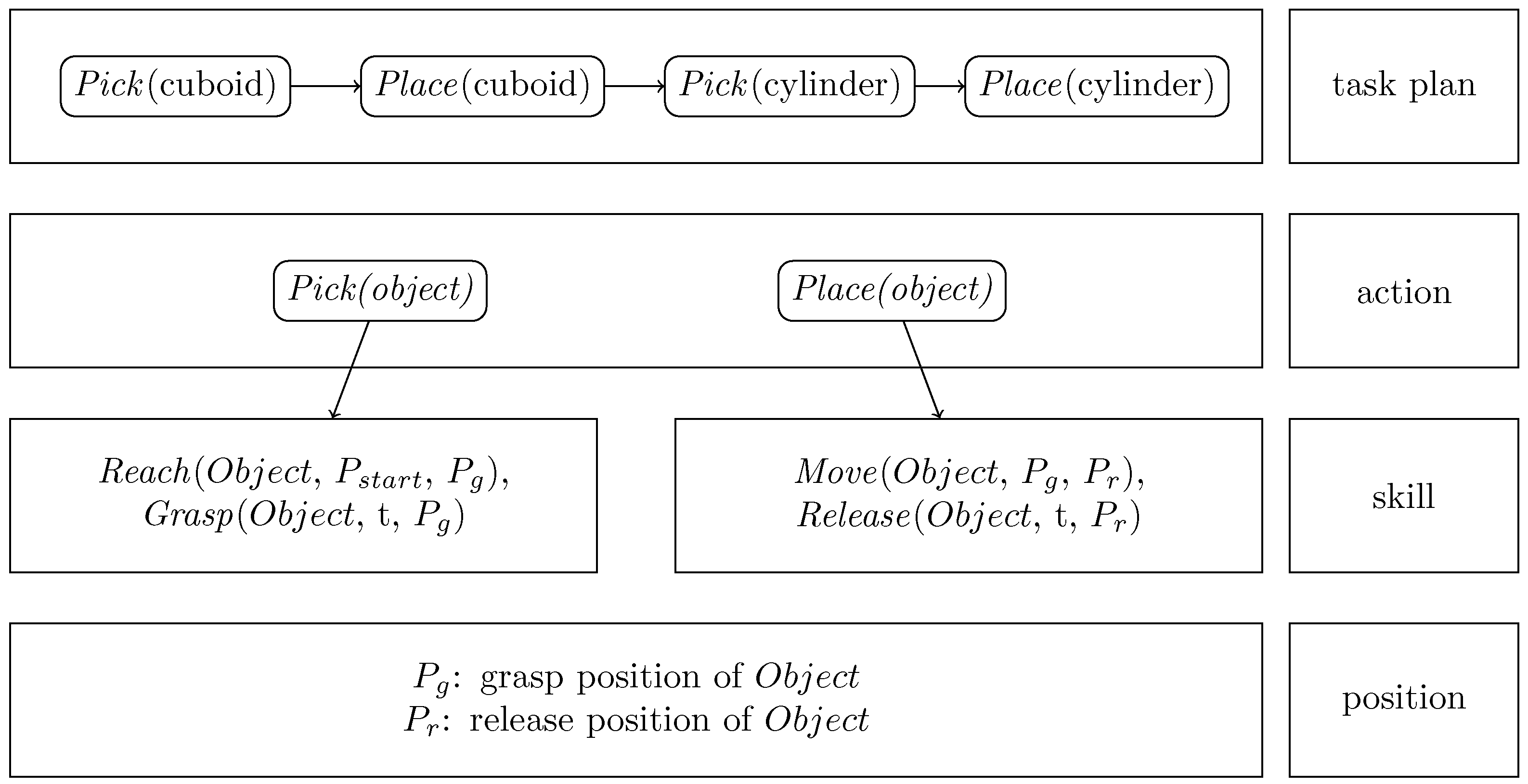
Figure 2.
Results of Hand Detection on RGB Images Using Different Models
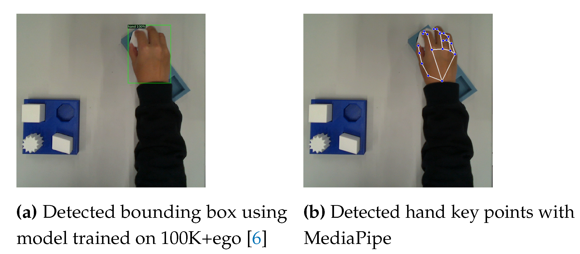
Figure 3.
Illustration of the differences between axis-aligned Bounding Box (Bbox) and Oriented Bounding Box (OBB) annotation
Figure 3.
Illustration of the differences between axis-aligned Bounding Box (Bbox) and Oriented Bounding Box (OBB) annotation
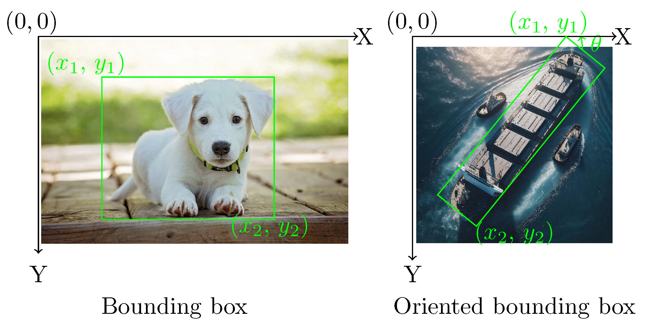
Figure 4.
Generated photorealistic images
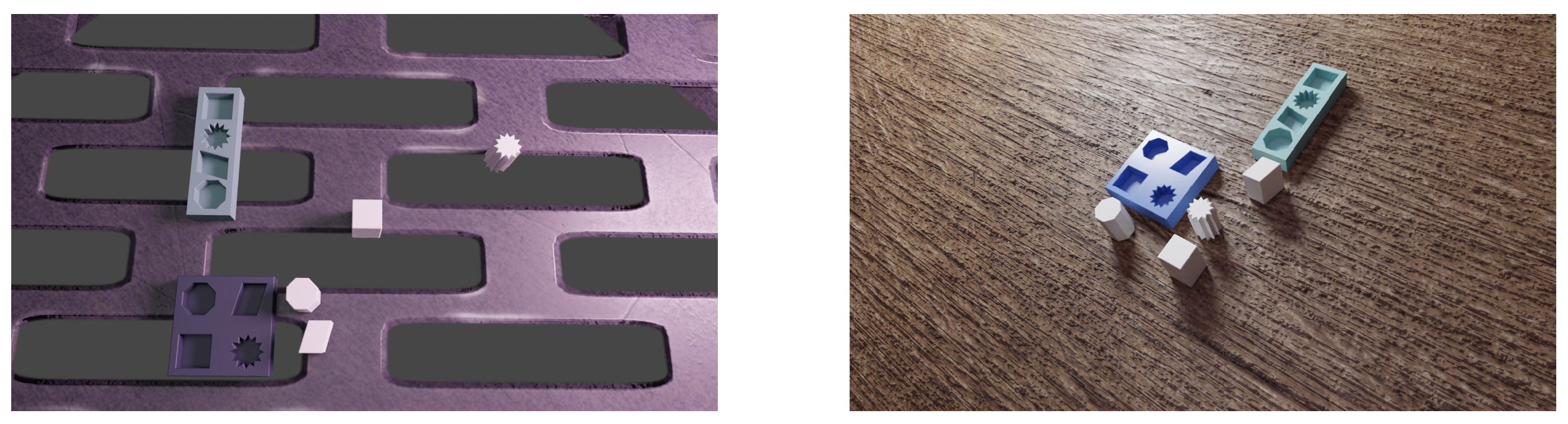
Figure 5.
Mapping motion from a human hand to a robot end-effector
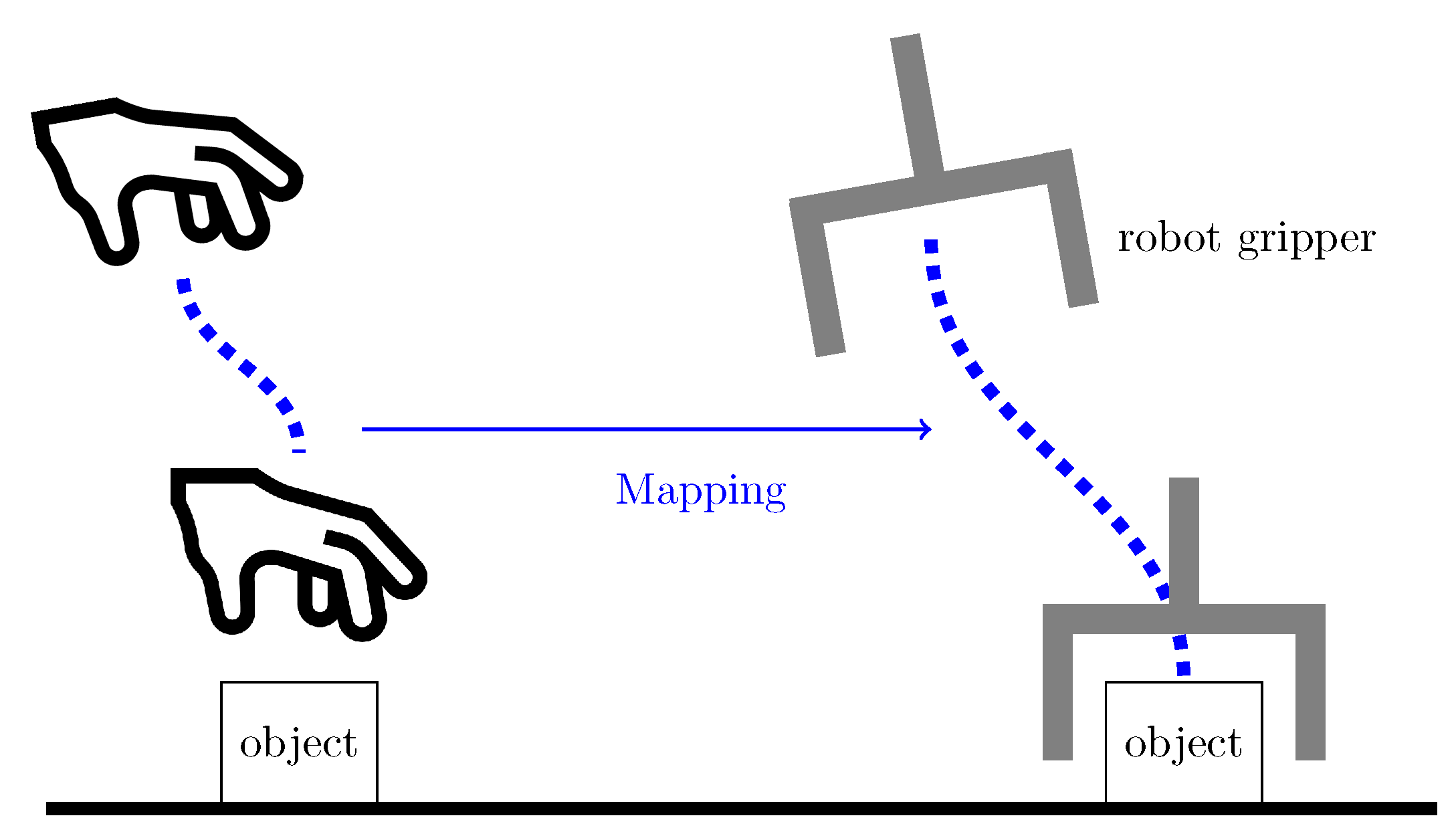
Figure 6.
Transform hand and object position from pixel coordinates to camera frame in world coordinates
Figure 6.
Transform hand and object position from pixel coordinates to camera frame in world coordinates
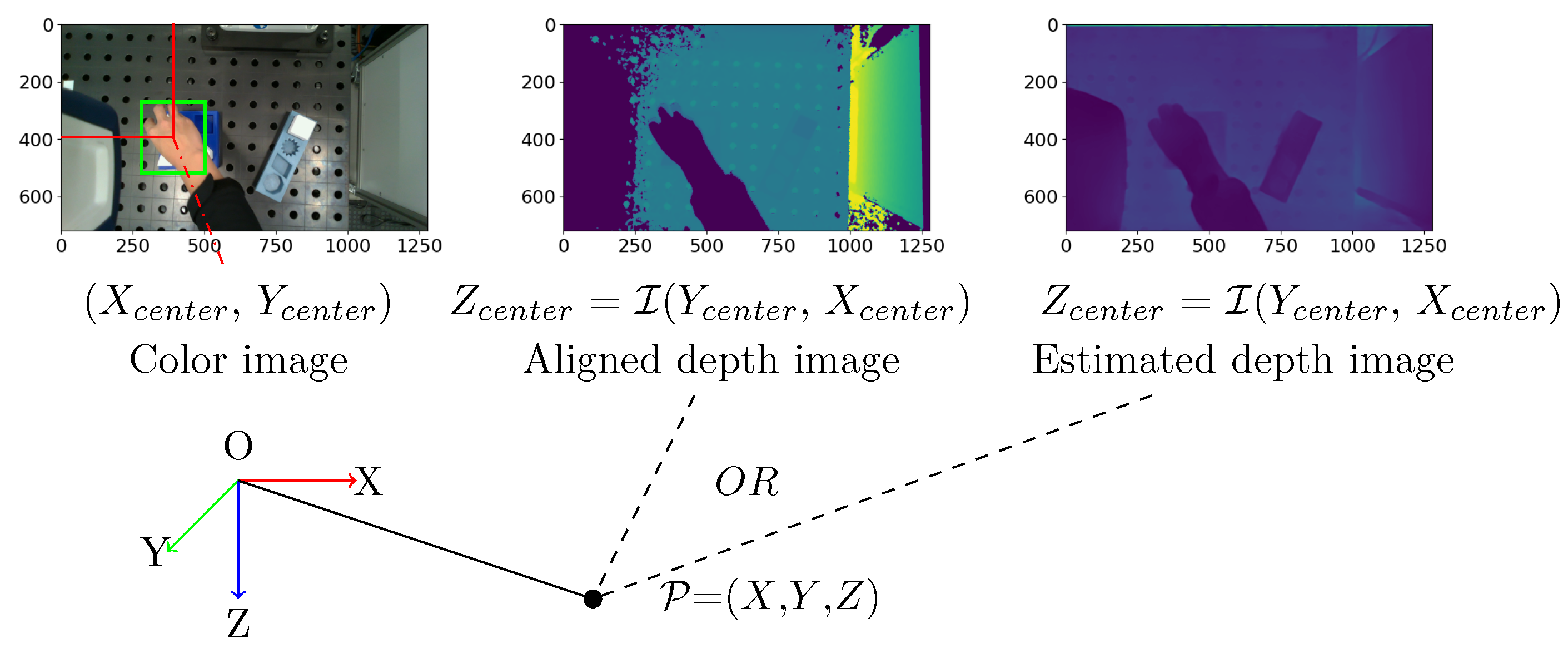
Figure 7.
Illustration of Pre-Grasp, Post-Grasp, Pre-Release, Post-Release Phases
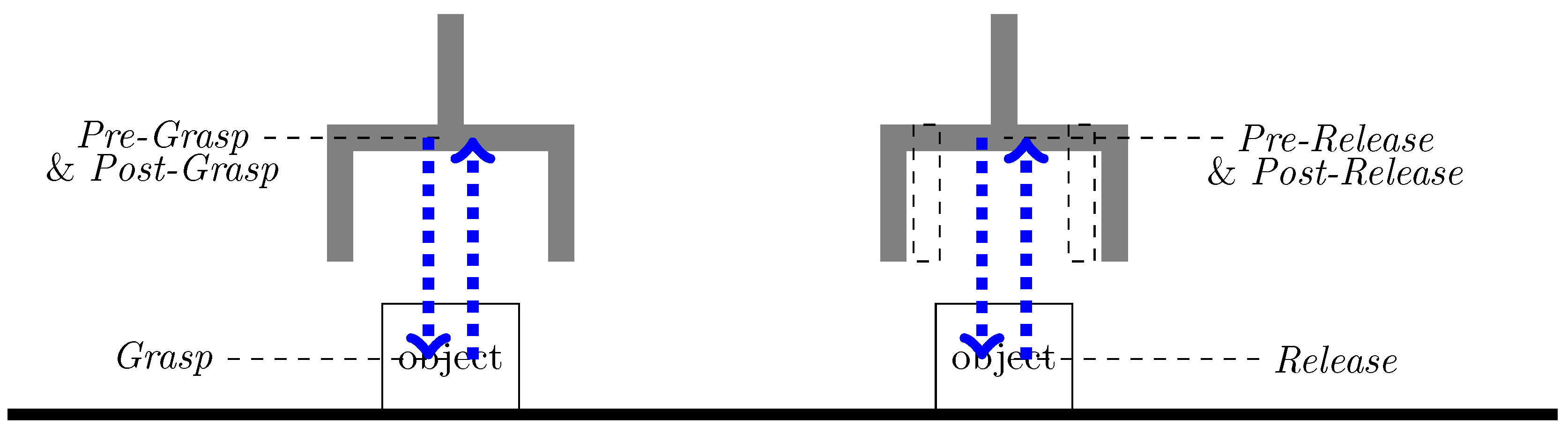
Figure 8.
Trajectory generation process
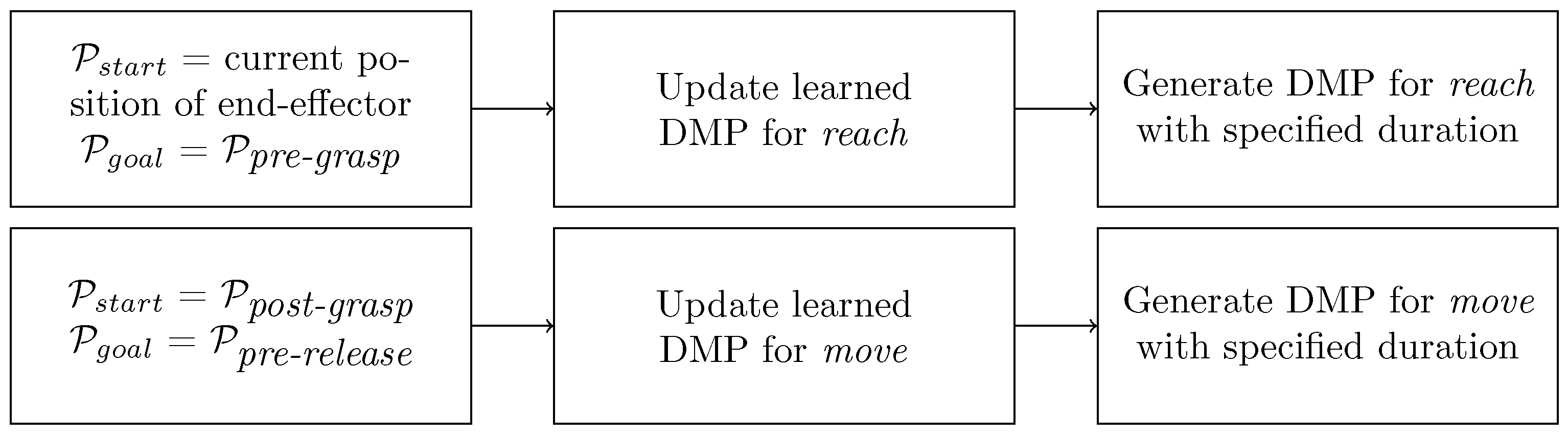
Figure 9.
(a) Demonstration setup; (b) Color image; (c) Aligned depth image
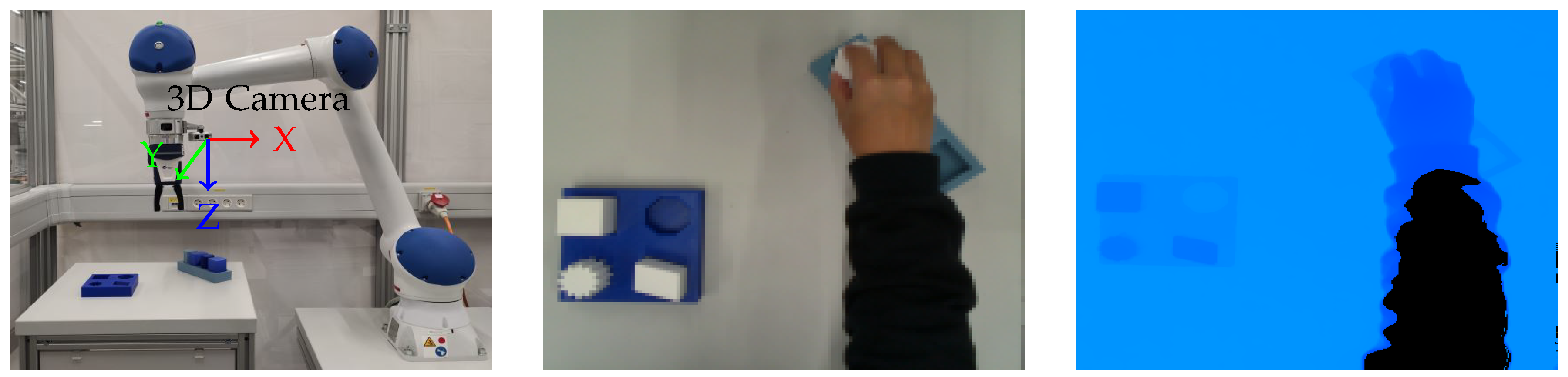
Figure 10.
An instance of missed hand detection by the model Faster-RCNN
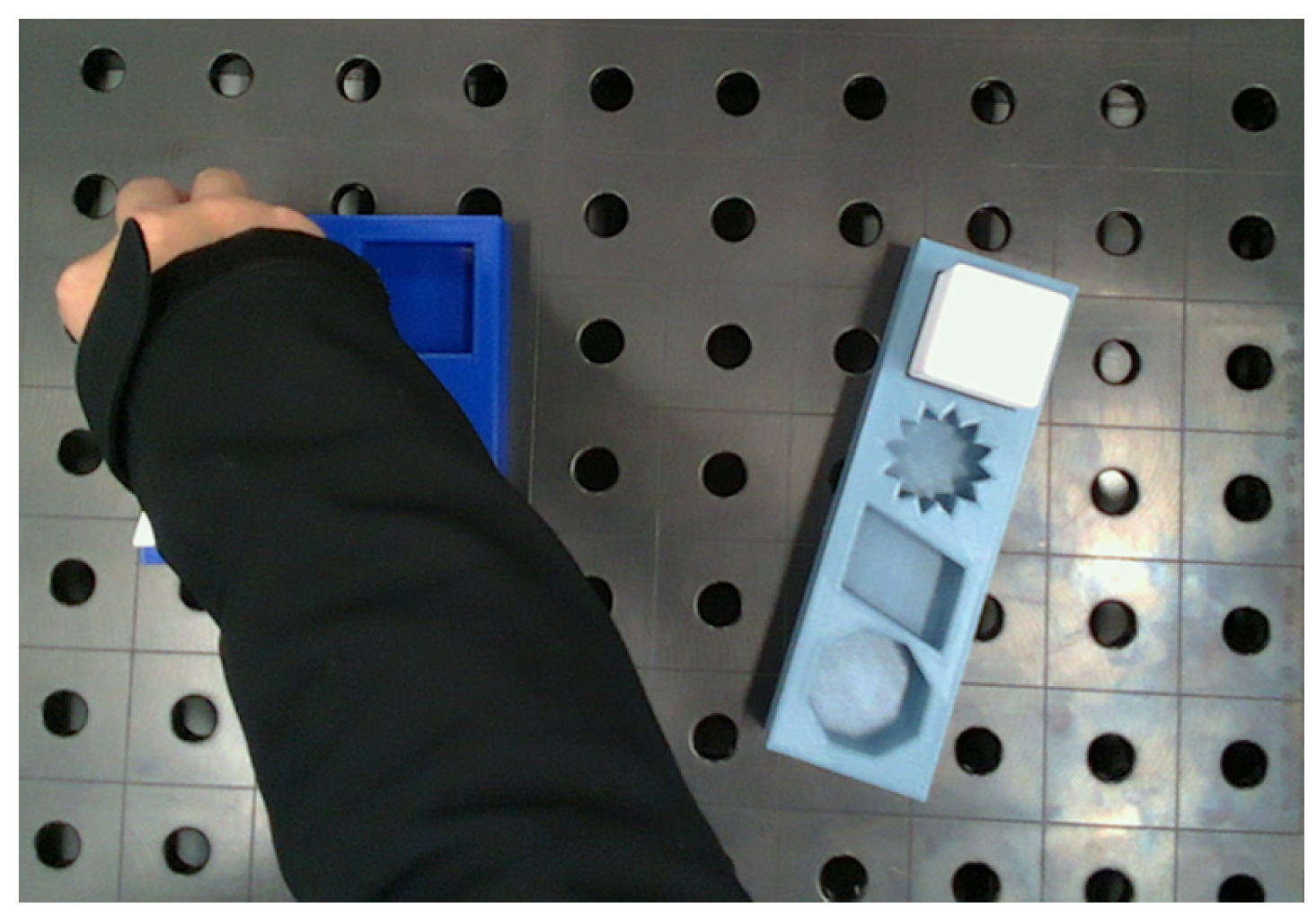
Figure 11.
Generated hand trajectory in camera frame with Faster-RCNN
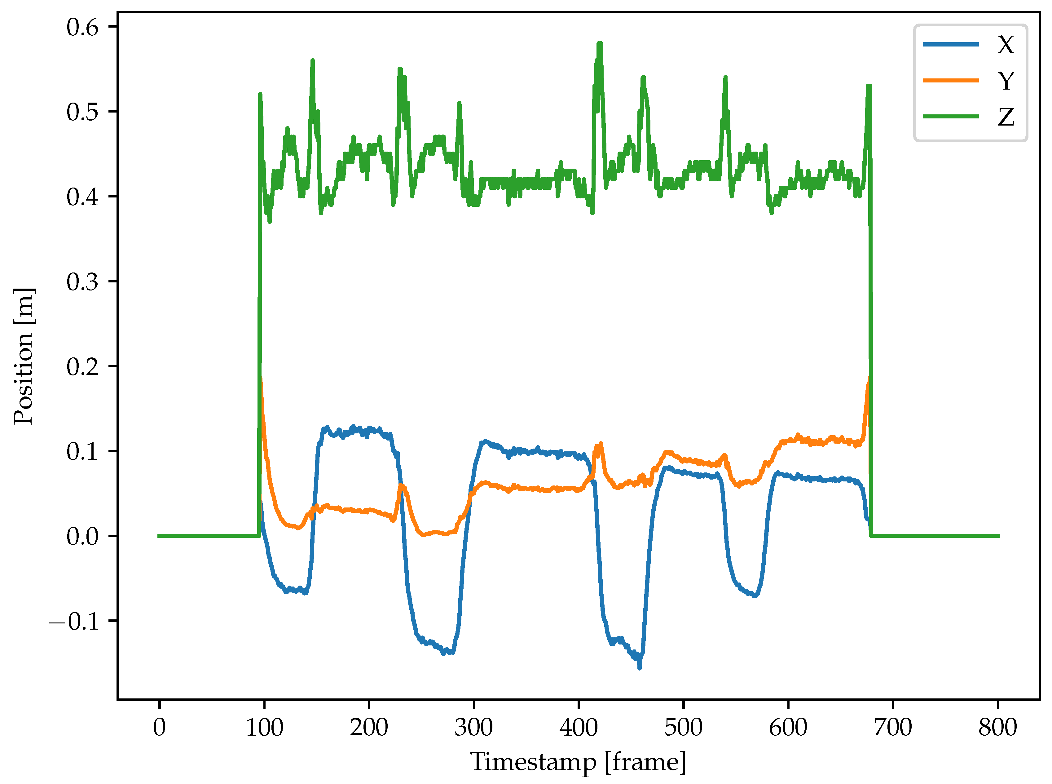
Figure 12.
Object detection results on real world images with Faster-RCNN
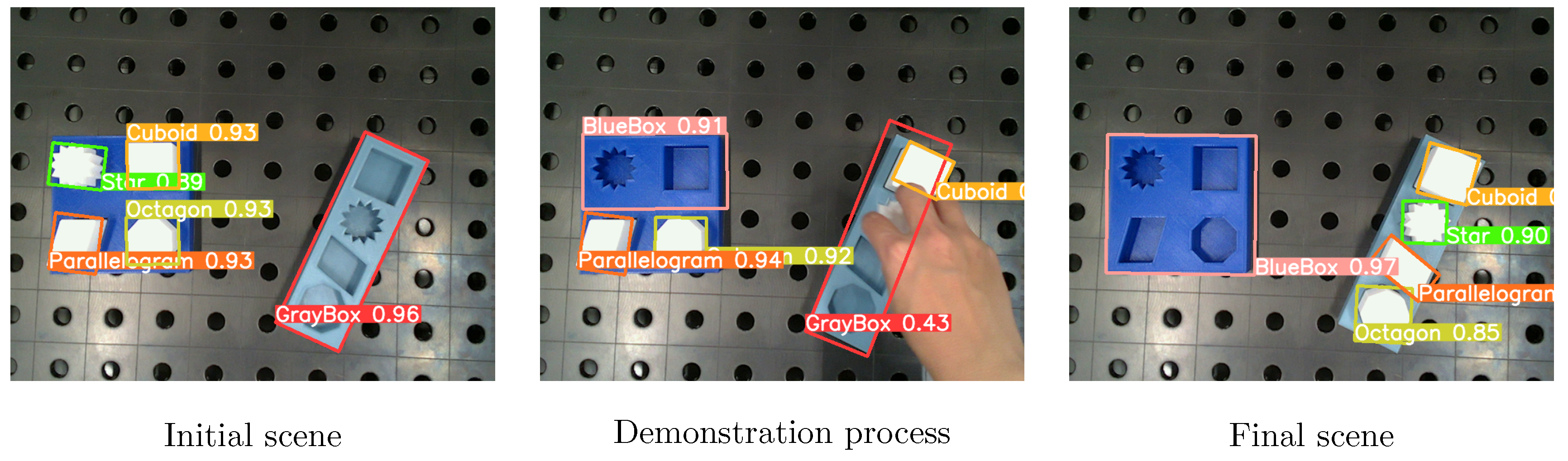
Figure 13.
Hand trajectory segmentation results
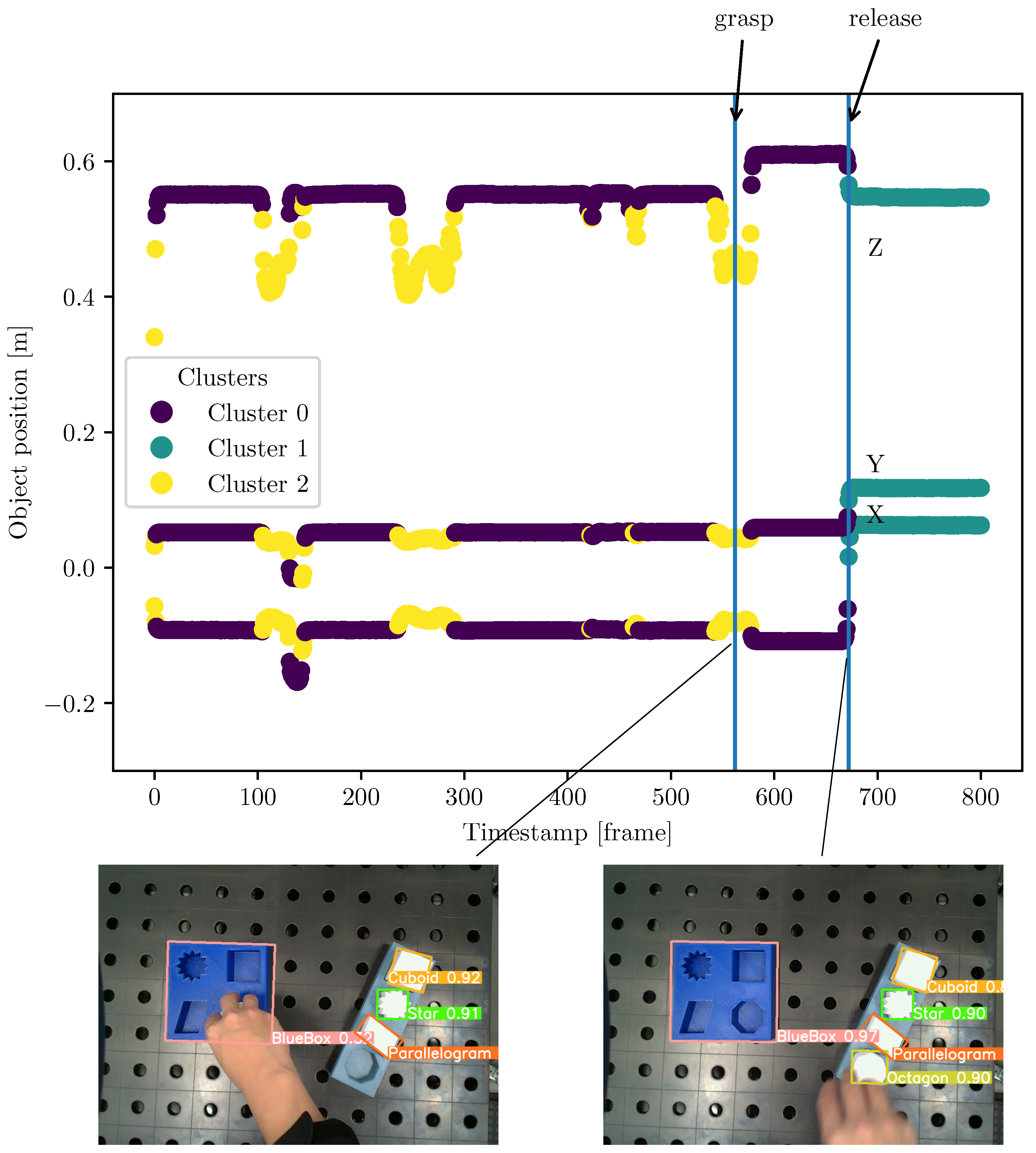
Figure 14.
Learned and updated DMP for representing reach with and
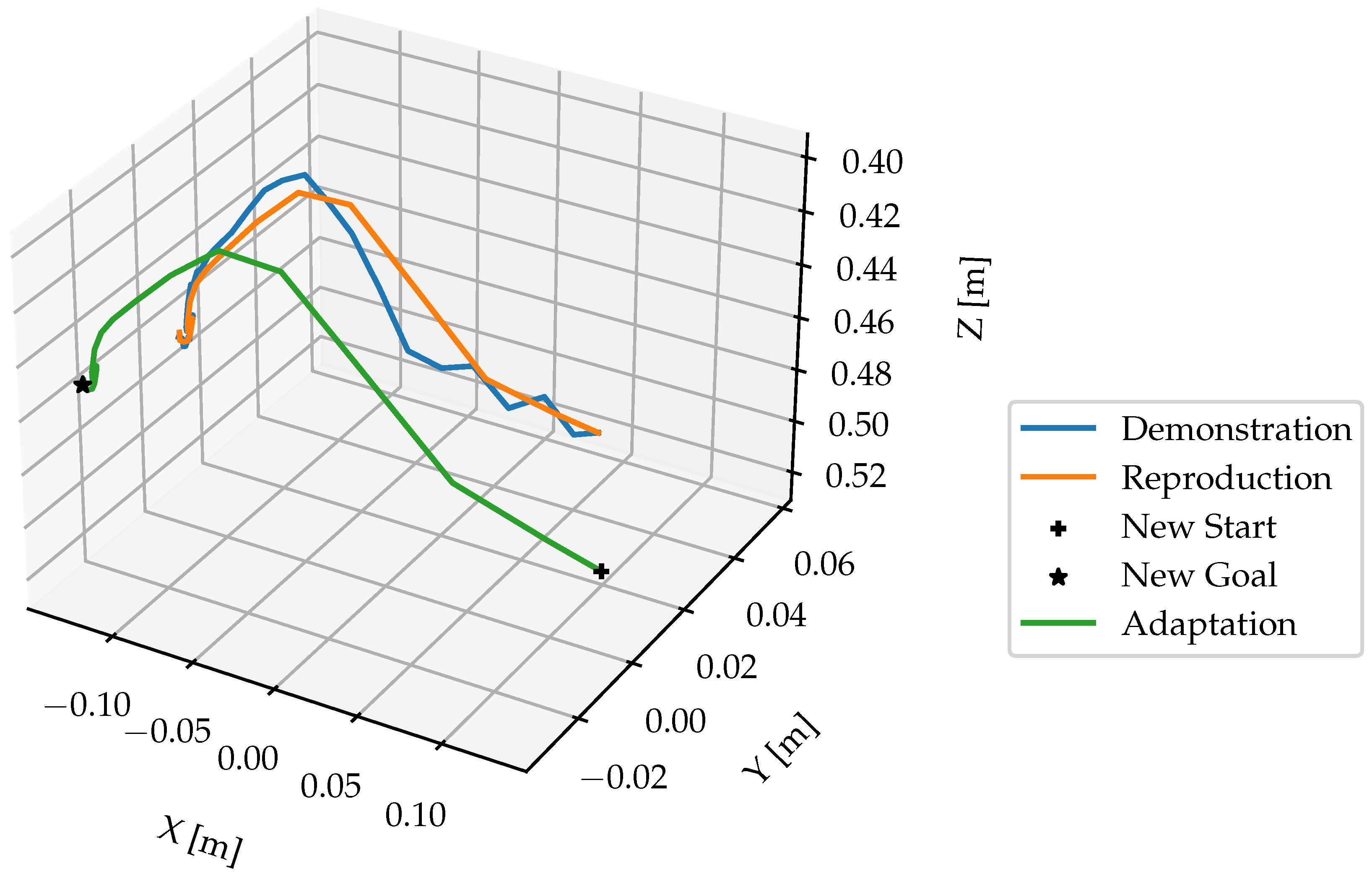
Figure 15.
Learned and updated DMP for representing reach with and
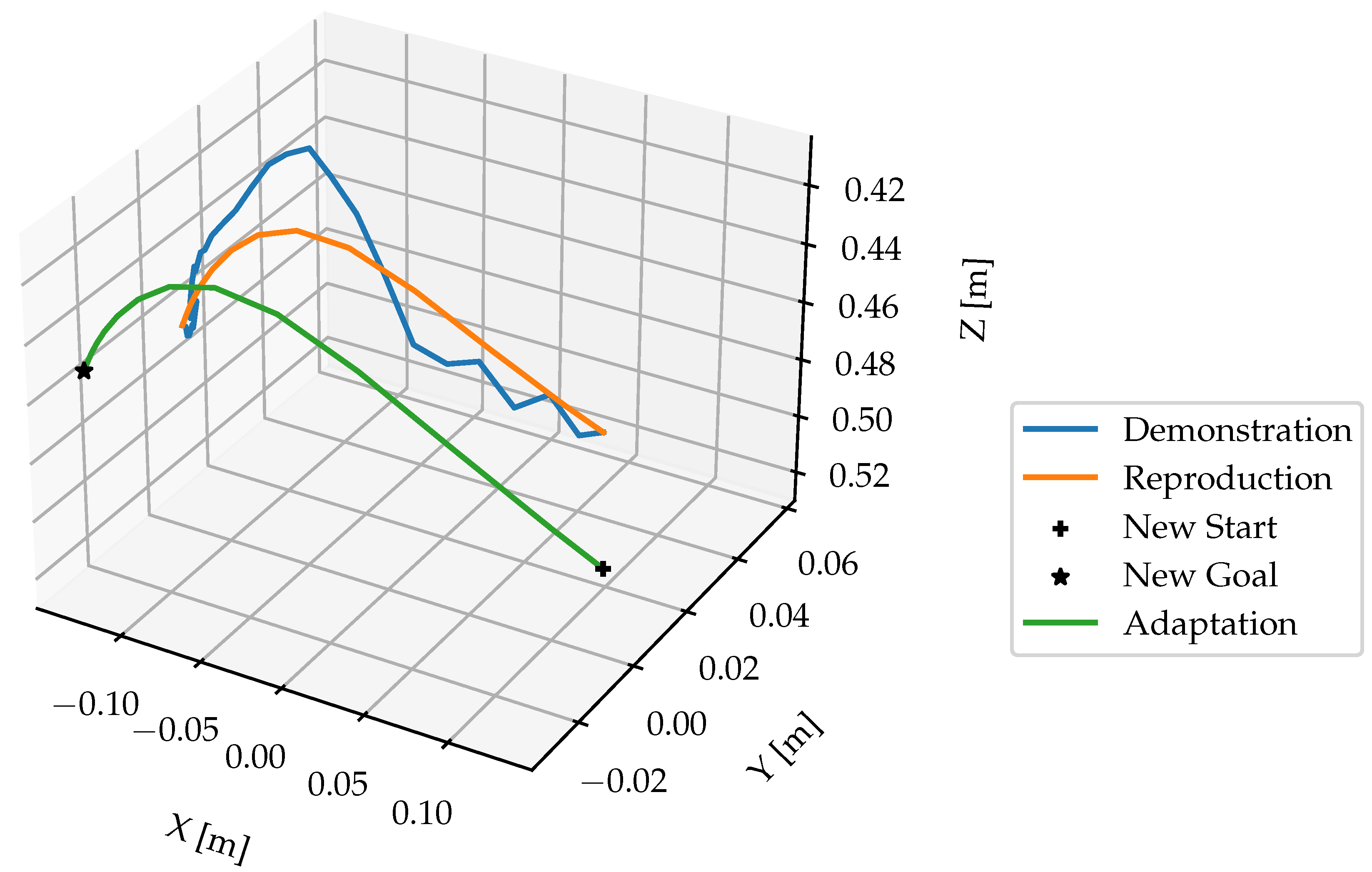
Figure 16.
Learned and updated DMP for representing move with and
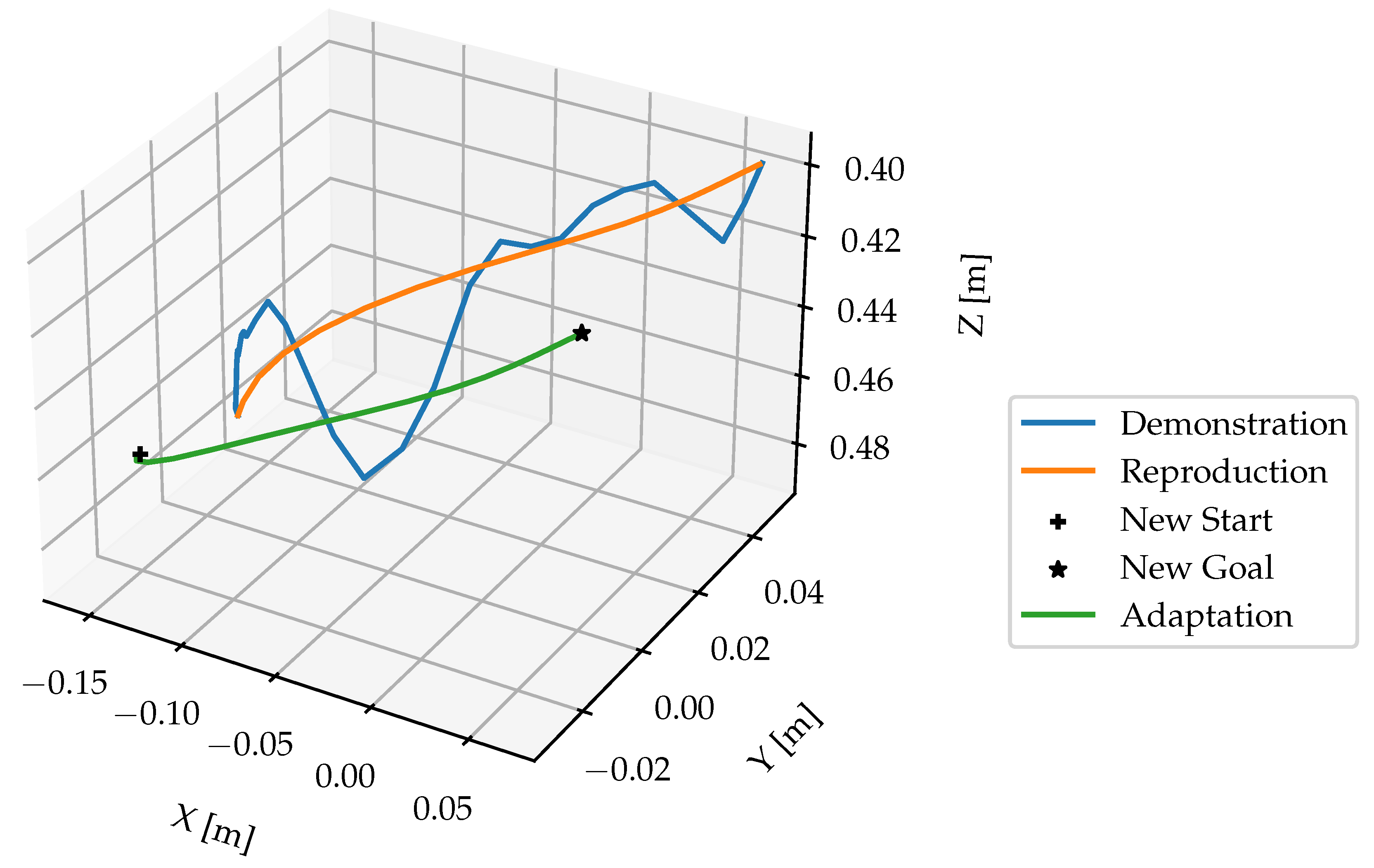
Figure 17.
Simulation environment
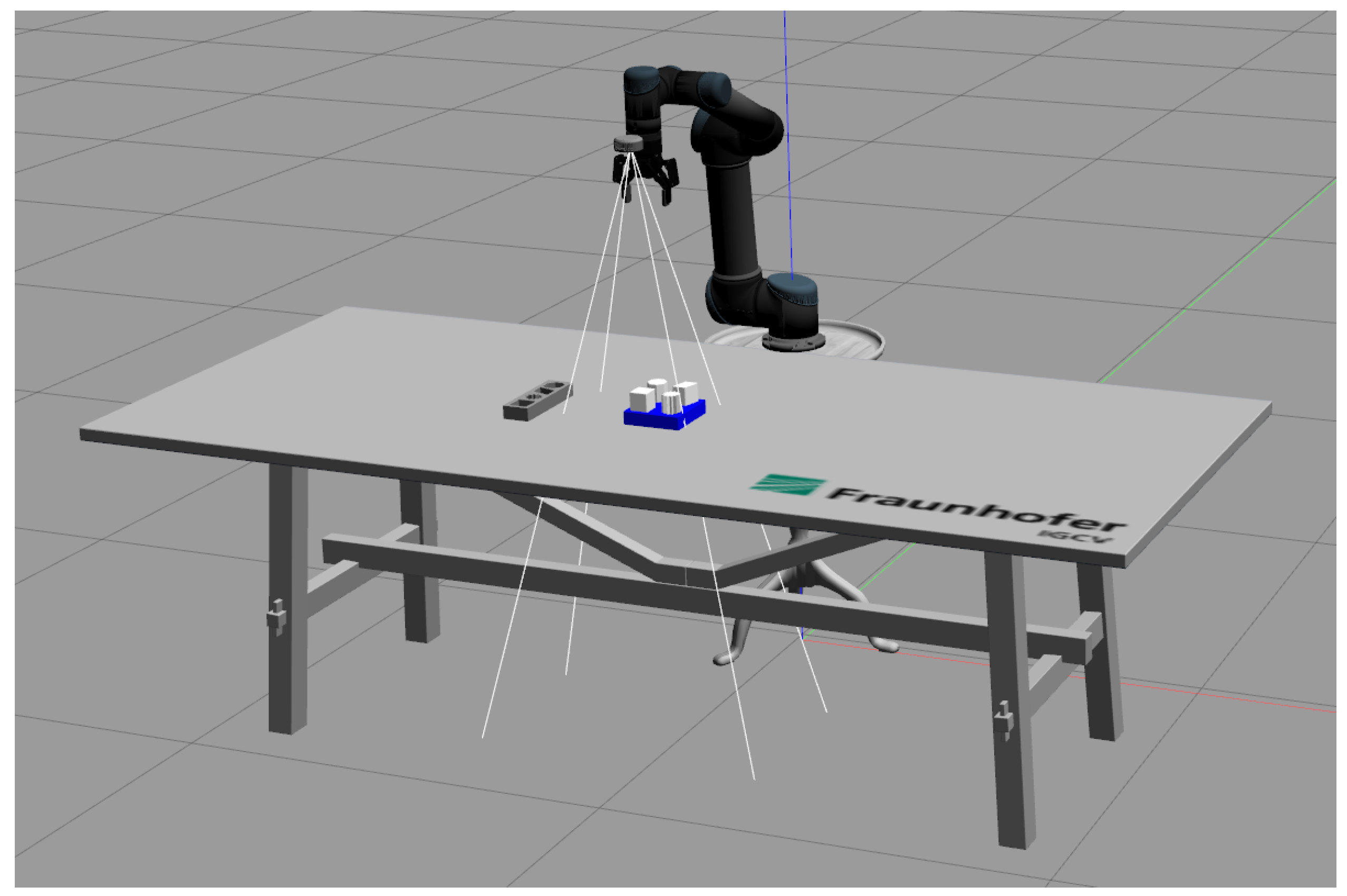

Table 1.
Representation of motion as skills for robots
| Actions | Skills | Segmented hand trajectories |
|---|---|---|
| Pick | Reach | |
| Grasp | , | |
| Place | Move | |
| Release | , |
Table 2.
Comparison of hand detection accuracy on recorded videos between Faster-RCNN and Mediapipe
| Faster-RCNN | MediaPipe | |
|---|---|---|
| Video 1 | ||
| Video 2 | ||
| Video 3 | ||
| Video 4 | ||
| Video 5 |
Table 3.
Object detection results on validation set
| Classes | Images | Instances | Precision | Recall | mAP50 | mAP50-95 |
|---|---|---|---|---|---|---|
| all | 3750 | 21821 | ||||
| GrayBox | 3750 | 3633 | ||||
| BlueBox | 3750 | 3670 | ||||
| Parallelogram | 3750 | 3637 | ||||
| Cuboid | 3750 | 3598 | ||||
| Octagon | 3750 | 3652 | ||||
| Star | 3750 | 3631 |
Table 4.
Object detection results on real world images
| Classes | Images | Instances | Precision | Recall | mAP50 | mAP50-95 |
|---|---|---|---|---|---|---|
| all | 971 | 5826 | ||||
| GrayBox | 971 | 971 | ||||
| BlueBox | 971 | 971 | ||||
| Parallelogram | 971 | 971 | ||||
| Cuboid | 971 | 971 | ||||
| Octagon | 971 | 971 | ||||
| Star | 971 | 971 |
Disclaimer/Publisher’s Note: The statements, opinions and data contained in all publications are solely those of the individual author(s) and contributor(s) and not of MDPI and/or the editor(s). MDPI and/or the editor(s) disclaim responsibility for any injury to people or property resulting from any ideas, methods, instructions or products referred to in the content. |
© 2024 by the authors. Licensee MDPI, Basel, Switzerland. This article is an open access article distributed under the terms and conditions of the Creative Commons Attribution (CC BY) license (https://creativecommons.org/licenses/by/4.0/).
Copyright: This open access article is published under a Creative Commons CC BY 4.0 license, which permit the free download, distribution, and reuse, provided that the author and preprint are cited in any reuse.


