
Submitted:
12 August 2024
Posted:
14 August 2024
You are already at the latest version
Abstract
The use of braces equipped with dissipative devices for the seismic strengthening of seismically prone reinforced concrete frames is among the most widespread methods, as it allows for high reductions in seismic vulnerability with inexpensive, quickly executed interventions, which can often be carried out mainly by the exterior, resulting in interruptions of use limited both in time and to only small portions of the building. The design methods of dissipative devices are based on the extensive use of pushover analyses capable of highlighting the structural deficiencies of the building and comparing the performances achievable by developing designs according to different methods and sizing criteria. In the present work, with reference to a case study represented by a four-story spatial frame having characteristics representative of design and construction common practice of the 1970s in Southern European countries, the performance of three different design methods is compared. The examined procedures differ for: methods for estimating the peak displacement response of the nonlinear systems, namely the well-known Equal Displacement Rule and the Equivalent (secant) stiffness and Damping rule; and criteria for distributing stiffness and strength of the bracing along the height, namely the distribution of stiffness and strength proportionally to those of the frame, and methods that vary the stiffness and strength along the height in order to minimize the eventual irregularity in elevation of the bare frame. The effectiveness of the procedures is checked by static pushover analysis and nonlinear response history analysis, performed by unidirectional and bidirectional input. Pros and cons of each procedure are summarized, all of them able to provide bracing designs that meet the performance requirements set during the design phase.
Keywords:
seismic retrofit
; dissipative bracings
; design methods
; direct displacement method
; force-based design
; behavior factor
1. Introduction
The evolution of the principles of seismic design of reinforced concrete structures introduced with capacity design has highlighted the need to seismically adapt many of the reinforced concrete frame structures designed in the 1960s and 1970s in the absence of specific rules for earthquake-resistant structures. Seismic strengthening techniques are very diversified [1], as the choice of intervention must be made in relation to the characteristics and weaknesses of the structure to be retrofitted [2].
For structures designed with anti-seismic design criteria that are now outdated, local interventions are often sufficient, such as shear reinforcement of nodes [2,3,4,5] beams and columns [6,7,8,9,10], confinement interventions in the areas of potential formation of plastic hinges [11,12], increase of column sections through jacketing [13], connection and reinforcement of non-structural elements such as infill panels [14]. When the structure is equipped with construction details that are insufficient to guarantee the limitation of the loss of resistance due to seismic action [15] and adequate ductility and dissipative capacity, the introduction of damping devices capable of dissipating most of the energy transmitted by the earthquake is one of the most common solutions for new and retrofitted structures [16,17,18,19,20,21,22,23,24,25,26,27,28]. When the structure as a whole, is provided with insufficient stiffness and resistance to horizontal actions, the use of bracing is one of the most historically widespread solutions [22,29,30,31]. However, their design must take into account the risk of an excessive increase in normal stresses on the columns, combined with the increase in the actions transmitted to the foundation. In this context, the use of bracing with uniaxial hysteretic or friction dissipative devices, or buckling restrained braces, allows to overcome the above-mentioned problems, in the latter case making the design of the stiffness and resistance of the bracing practically independent [32,33,34,35]. Bracings equipped with hysteretic dissipative devices are able to significantly reduce interstory drifts and dissipate large amounts of energy, preserving the frame elements from plasticization.
In this field, since the 1990s, dissipative bracing design techniques have been proposed, which using the evolution of the method for predicting the seismic response of framed structures, have produced efficient procedures aimed at solving the main issues that arise during the design phase. Namely, the main issues to be solved in the design of the dissipative bracing are: - choice of the performances that must be guaranteed; - design of the global values of stiffness and resistance of the bracings; - distribute the stiffness and the resistance of the bracing in elevation and in plan (this issue is critical for in elevation or in plan irregular structures); - perform the executive design of the individual bracings and dissipative devices in relation to the specific characteristics.
With reference to the performances to be guaranteed, given the high stiffness and the great dissipative capacities that dissipative braces are able to guarantee, from the first formulations [32] to the more recent ones[16,17,19,36,37] the braces are designed in such a way as to avoid the plasticization of the elements of the pre-existing frame and the damage of the non-structural elements.
Since the formulation of the first methods [32], the use of an equivalent SDOF for the evaluation of the global stiffness and resistance values to be assigned to the bracing systems has proven to be among the most effective techniques and is therefore used in almost all procedures. In this regard, recent seismic codes [38,39,40] provide two procedures for estimating the peak displacement response of the nonlinear systems, namely the well-known Equal Displacement Rule (suitably modified in the field of rigid structures) EDR1, or on the basis of the substitute structure procedure proposed by Shibata and Sozen [41], according to which the displacement of a nonlinear MDOF structure can be estimated, consistently with the equivalent linearization technique [42], by evaluating the peak displacement of an elastic SDOF with equivalent (secant) stiffness (or vibration period) and damping ED2.
Regarding the distribution of stiffness and resistance in elevation and plan, two are the most followed approaches: - distributing stiffness and resistance proportional to the characteristics of the structure to be strengthened [19,43]; - distributing stiffness and resistance in such a way as to correct the irregularities in plan and elevation present in the structure [17,44,45].
In more detail, several researchers [46,47,48,49] implemented the Direct Displacement Based Design (DDBD) procedure [50,51] to design the dampers. The procedure proposed by Kim and Choi [46] resembles the capacity spectrum method. In this approach, a performance point is evaluated as the point where the displacement demand of the structures coincides with their plastic deformation, by means of the acceleration displacement response spectrum. To evaluate the required damping to meet the target displacement criteria, instead of using a random hit-and-trial method, the damping is calculated as the difference between the effective damping and the damping provided by the structure. In the case of hysteretic dampers, iterations are necessary because incorporating the devices increases the structure's stiffness, which ultimately increases the overall stiffness. The procedure was applied to 10-story and 20-story buildings, and the results demonstrate the method's effectiveness, as the structures modeled using this approach have maximum displacements equal to the target displacement.
Mazza and Vulcano [48]proposed a design method based on Displacement-Based Design (DBD) for the design of dissipative bracing in such a way that required performance, namely the control of interstory drift, can be achieved when subjected to earthquake motion. The braces are designed at each story by means of a proportional stiffness criterion, in which the stiffness of braces is selected proportional to those of the unbraced frame. To this aim, an iterative approach has been adopted to assign the ratio of these stiffnesses depending on the strength of the unbraced frame.
Di Cesare and Ponzo [17] developed a procedure to design the mechanical characteristic of dissipative bracing for RC structure. In this procedure, the displacement on the top story is assumed as a control parameter, and to control the interstory drift the stiffness and strength of each story is modified accordingly along the height of the building. The procedure was applied to different case studies. From the results, it was found that the hysteretic energy dissipative bracings were effective to obtain the required performance of the structure, confirming the efficiency of the proposed method. The method also highlighted the criteria’s to avoid unnecessary overloading on structural members.
Ferraioli and Lavino [18] proposed a design method aiming at improving the procedure of Mazza et al. [16], established on Displacement Based Design (DBD) by using the capacity spectrum method. The proposed method addressed some critical point that were not incorporated in the previous methods, like damped braces and frame interaction that produces an increment of the axial load in the columns of the frame with consequent decreasing of the available ductility, torsional effects in asymmetric buildings, effects of soft story, the effect of the modification of the first modal shape and therefore of the corresponding distribution of seismic forces along the height of the frame due to the modification of the resisting system from Moment Resistant Frame (MRF) to Concentric Braced Frames (CBF), as well as the effects of the higher vibration modes in high-rise frames.
The proposed procedure is divided into two parts: one is concerned about the design of dissipative bracings and defining the position and properties in the second, the design force pattern is varied in order to incorporate the higher mode contributions. In order to check the validity of the design method, nonlinear time history analysis has been performed on a plane RC frame and then on a real school building; the results showed the effectiveness of the structure in addressing the aforementioned issues. Adaptive pushover analysis was performed to accurately estimate the target displacement, as it is important because due to the introduction of the damped brace, the axial force in the column increases, resulting in a reduction of deformation capacity. It was also found that the procedure is able to distribute the damper stiffness and strength properly along the height of the structure and thus gives uniform story drift distribution, resulting in the reduction of interstory drift.
Bruschi et al. [19] proposed another procedure for seismic upgrading of a structure using dissipative bracing based on the concept of the equivalent elastic high damped SDOF system, having equivalent viscous damping and secant stiffness at the performance point. Initially, a step-by-step procedure is performed to evaluate the global properties of the damped bracing system that includes the determination of the main capacity curve of the frame by pushover analysis, then a target displacement has been identified and a tentative equivalent SDOF bilinear curve of the braced frame is constructed; then an iterative procedure has been used to find the equivalent viscous damping ratio of the damped brace system together with the actual final stiffness and strength of the damped braces; the final configuration is found when the braced frame seismic demand matches the required target displacement on the damped acceleration displacement response spectra. Once the global parameters of the equivalent SDOF are found, stiffness and strength of the bracing are distributed along the height of the structure proportionally to the characteristic of the frame to be strengthened. Then the damped bracing is positioned within the story of the structure.
In the following sections, through a case study represented by a four-story spatial frame having characteristics representative of design and construction common practice of the 1970’s in Southern European countries, the effectiveness of two of the aforementioned procedures are compared with a simpler one, based on the principles of current seismic codes. The latter pursues performance based design through the force approach, with the control of the displacement demand. In details, the two procedures, namely the procedure proposed by Di Cesare and Ponzo [17] based on the equal displacement rule EDR1, and the procedure proposed by Bruschi et al. [19] based on the Equivalent Damping approach ED2, are chosen since they are characterized by a balance between the simplicity of the method and the effectiveness of the resulting design.
2. Design Methods
Most of the design method for retrofitting frames by inserting dissipative bracings integrates the pushover analysis of the multi-degree-of-freedom (MDOF) model of the bare frame (F) with the response spectrum analysis of equivalent single-degree-of-freedom (SDOF) systems, initially to estimate the global nonlinear displacement response of the frame to be strengthened. Then the strengthening dissipative braces are designed by setting a required performance goal, usually identified with a maximum total or interstory displacement. Then the global parameters of the SDOF braced frame are converted into thoseof the corresponding MDOF, and the stiffness and the strength of the bracing are distributed in plan and in elevation according to different criteria. Among the main issues that characterize the design phase, here attention is focused on two that distinguish the procedures in the literature: - the method for evaluation of the characteristics and the displacement demand of the SDOF equivalent system; - the criteria and the methods used to distribute stiffness and strength of the bracing in elevation. In the following, the two aforementioned methods in literature that exemplify the main strategies applied are compared with a very simple and straightforward method, in which some details that assume a paramount relevance in determining the response of the system are clarified and discussed.
2.1. Di Cesare and Ponzo Method (DCP) [17]
This method, according the prescription of EC8 [38,39], is characterized by the modeling of the equivalent SDOF by an elastic-perfectly plastic system (post-yielding stiffness kH=0), with elastic stiffness k corresponding to the secant stiffness at60% of the maximum base shear of the actual MDOF, and strength evaluated by imposing that the area under the actual pushover curve is equal to the area under the equivalent elastic-perfectly plastic curve, as prescribed in [40]. Aiming at determining the displacement demand of the nonlinear system, initially an elastic equivalent SDOF is defined, which represents the dynamic characteristics of the first vibrating mode of the actual multi degree of freedom system; then the Equal Displacement Rule (Figure 1b), i.e., displacement demand of nonlinear SDOF d*max equals to the displacement demand of elastic SDOF d*el is used having for SDOF having period of vibration T* >Tc (Tb and Tc being the starting and the ending abscissa of the flat branch of the pseudo-acceleration response spectrum that characterized the input), while the conservative equal energy rule [50,51] is assumed for T* <Tc; according to the latter assumption, the displacement demand is amplified by a coefficient α, . = del*α , being α=(q*2+1)/(2q*) derived by the equal energy criteria between the static representation of the response of elastic and elastic-perfectly plastic system (α=1 for T* >Tc). Regarding the distribution of the stiffness and strength of the dissipative bracing along the height of the structure, the initial tentative distribution is proportional to the elastic stiffness of the bare frame. Correction are imposed if the ratio of total stiffness of two consecutive floor Ki,DBF/Ki+1,DBF exceeds 0.3 or is less than -0.1, and the ratio Δρi=ρi/ρi-1 is not in the range 0.8≤ Δρi ≤1.2, ρi= Vi,DBF/Vi,design being the ratio between the i-th story total strength of the dissipative braced frame and the design story shearThus, the procedure ensures that the stiffness and strength are distributed along the height of the braced building according to seismic code regularity criteria [40], consistent with the criteria in [38]. This aims at resulting in a uniform distribution of displacements and controls the maximum interstory drifts to stay within target limits.
Thus, according to the flow chart in Figure 1a, the first step in this procedure is to determine the mechanical characteristics of the equivalent SDOF system for the bare structure. Capacity curves for both main directions of the building are obtained using pushover analysis. The structure's idealized elastoplastic force-displacement relationship is defined using the following parametersSDOF equivalent mass m*being mi= the story mass, and the eigenvector of the first mode in the relevant direction, normalized with respect to top story component, the Γ1,BF ). Thus, equivalent SDOF force F* and displacement d* parameters are obtained from the attendant values of the actual MDOF parameters by division first mode transformation factor Γ1,BF. yield force (Fy* = Vby /Γ1),
yield displacement (dy,BF* = dy,BF / Γ1) and ultimate displacement du,BF* = du,BF / Γ1, as detailed in Annex-B of [37], while the elastic stiffness (kBF* = Fy,BF* / dy,BF*) or maximum ductility ( μBF* = du,BF* / dy,BF*) are the same of equivalent SDOF and actual MDOF.
Step 2 involves evaluating the properties of the equivalent SDOF system of the dissipative braced frame. An iterative procedure should be performed separately for each main direction. The damped bracing (DB) system is idealized as an elastoplastic system defined by the yield force (FDB), elastic stiffness (kDB), and design ductility (μDB).
Given a maximum displacement dmax,DBF* for the equivalent SDOF system
of the braced frame DBF under the Basic Design Earthquake (BDE), the target ductility μ*T,BF of the existing bare frame (BF) is defined by:
If the design goal is for the structure to remain elastic (μT,BF∗ = 1), then dmax,DBF* must be less than or equal to dy,BF*. Otherwise, if a limited inelastic capacity is allowed, target ductility (μ*) can range from 1.5 to 3, depending on whether the mechanism is brittle or ductile, respectively. In this case, dy,BF* <dmax,DBF* ≤ du,BF*.
Assuming a design ductility μDB for the equivalent SDOF bracing system (DB), optimal ductility values range from 4 to 12, depending on the properties of the hysteretic device and the Serviceability Design Earthquake (SDE). Consequently, the yield displacement of the equivalent SDOF bracing system dy,DB* is calculated by:
At the jth step of an iterative procedure, the equivalent period TDBF*j , the total elastic stiffness kDBF*j of the DBF structure, are determined by means of the idealized elastoplastic behavior of the braced structure using Eqs (3a) and (3b).
where α=1 is initially retained. The stiffness of the equivalent SDOF dissipative bracing system is obtained as the difference between the total stiffness and the frame stiffness , and the yield force of the dissipative bracing as .
If in Equation (3a), TDBF*j<Tc is found, a new idealized bilinear curve have to be evaluated on the basis of the force displacement curve obtained by the sum of the contribute of the actual bare frame and the properties of the dissipative bracing at the jth iteration, thus evaluating and the attendant value of the behavior factor
at the jth iteration evaluated as
and the iterative procedure starting from equation (3a) with the updated value of α should be performed.
Once the characteristic parameters of the equivalent dissipative bracing are evaluated, the actual dimensions and yielding force of the dissipative bracing can be evaluated as previously described. It has to be remarked that the authors suggest applying an amplification factor γx=1.2 on the yielding force of each dissipative bracing to avoid either buckling or premature yielding under the MCE (maximum considered earthquake).
The proposed procedure suffers from a) the conservative estimate of the displacements for systems with T*<Tc based on the equal energy criterion already reported by the authors; b) the assumption of a further 20% increase in the resistance of the device (γx=1.2 not taken into account in this work); b) the initial assumption of a distribution of the stiffness and resistance characteristics of the dissipative braces proportional to that of the frame, providing for a correction only if the elevation regularity requirements of the Italian code [40] are not satisfied. Such correction, desired to correct the elevation irregularities of structures not designed for seismic actions, should be provided for already in the design phase of the bracing system; c) an approximate evaluation of the resistance of the frame at each floor obtained on the basis of the secant stiffness obtained in correspondence with an unspecified level of the external seismic action
2.2. Bruschi, Quaglini, and Calvi Method (BQC) [19]
The main differences of the previous procedure with that proposed in [19] depend 1) on the method for evaluation of the displacement demand based on the equivalent damping. The equivalent damping is evaluated on the basis of the hysteretic behavior of dissipative bracing and existing bare frame, as defined in procedure 2 of the Italian Building Code [40], according to a concept widely acknowledged in the literature proposed by Shibata and Sozen [41]; 2) the modal properties of the bare frame are used to evaluate the target displacement demand of the DBF, by assuming a design pattern of the DBF displacements along the height of the frame that is proportional to the first modal shape of the bare frame, and a target value of the maximum inter-story drift; 3) according to item 2), the distribution of the stiffness and resistance characteristics of the dissipative braces are proportional to those of the frame.
Regarding the 1st issue, the equivalent bilinearized SDOF system differs from the one described in the previous procedure by the stiffness of the elastic branch, which here is settled as the initial elastic one rather than the secant value at 0.6 Vbmax as done in the previous procedure, and the shape of the second branch, which is characterized by a post-elastic stiffness KH>0, evaluated together with the displacement demand d*max and the yielding force F*y on the basis of the following relations:
being the effective period evaluated on the basis of the effective stifness, i.e., secant stiffness keff=F*u/d*max, E*H the energy absorbed (the area under the force-displacement curve) by the actual SDOF system up to the demand displacement, and a coefficient that reflects the energy dissipation capacity of the system, that is settled =1, 0.66, 0.33 for structures with high, medium, or low damping capability respectively, the latter depending on the stability of the hysteresis cycles. Equation 5c is obtained by imposing that the area under the equivalent bilinear curve is equal to E*H. An iterative procedure is used to find the equivalent damping value and the period of vibration T* which are consistent with the displacement demand.
The main steps of this procedure can be summarized, as shown in the flowchart in Figure 2a and ADRS in Figure 2b,c, as follows:- the main capacity curve of the bare frame is evaluated using static nonlinear analysis, and the MDOF converted into equivalent SDOF system as described in the previous method; the target displacement of the system dmax is chosen according to the design performance that is required to the dissipative bracing. The authors suggested to choose the target displacement in order to protect both structural and non-structural elements, corresponding to a maximum inter-story drift of the dissipative braced frame Δdi,max,DBF/hi in the range 0.5% ÷ 0.75%, being hi the inter-story height of the ith story; thus, the target value of the top story displacement of the DBF is evaluated as
The target top story displacement of the DBF is converted in the target displacement of the DBF equivalent SDOF, and the capacity curve of SDOF system is converted into equivalent bilinear curve with hardening. Then, the characteristic parameters of the equivalent DB system are designed depending on the design value of the dissipative bracing ductility μDB=, and the equivalent damping of the damped brace *eq,DB=63.7 (μDB -1)/ μDB. The latter can be chosen in the range 4≤ μDB ≤10, according to the dissipative device technology. Then, the equivalent viscous damping *eq,BDF, yielding displacement , and ultimate strength of the DBF SDOF equivalent system, i.e., the strength at the maximum displacement = (xx=BF,DB,DBF) are determined by the iterative procedure based on equations 5,6, 7a-d, as follows:
When the suitable damping and yield strength of the braced frame has been determined, the strength of the SDOF dissipative bracing is obtained as . Thus, for each brace, the strength (equation (8)) and stiffness (equation (9)) has been determined as follows:
being nd the number of the bracing at each story, and αij the inclination of the jth bracing of the ith story.
The BQC procedure is particularly efficient for regular bare frame, as it is able to take into account the high hysteretic capacities of the bracing systems equipped with dissipative devices through the evaluation of the equivalent damping. However, it leads to an oversizing of the bracing due to the choice of designing the strengthened structure with the same modal shape as the bare frame, assuming a highly precautionary design displacement of the braced structure in the presence of a marked irregularity in the structure to be strengthened (see eq.6), characterized by a value of much larger than 1/np (np being the number of story), a value that would characterize the behavior of a structure designed to exhibit a constant interstory drift.
2.3. Simplified Method (CAD)
A simplified method is derived in order to investigate the efficiency of procedures that aim to mitigate the effect of possible irregularity along the height of the bare frame. The main difference with the previous method, besides using elementary relations that are easy to understand by the common practitioner, lies in the desire to obtain for the braced structure a displacement profile characterized by constant inter-story drift along the height. The procedure aims at obtaining uniform damage in the presence of earthquakes of unexpected intensity, and to reduce the amount of material used for the braces.
According to the simplified procedure, characterized by a flowchart and a representation in the ADRS shown in Figure 3a and 3b respectively, once the design drift Δd is chosen, the target eigenvector of the BDF structure is settled as =zi/HT , being zi the height of ith story above the level of application of the seismic action, and HT the total height of the frame. The target displacement is evaluated as = Δd * HT, the mass of the equivalent SDOF as m* =, and the first mode transformation factor Γ1,DBF=. In order to evaluate the behavior of the bare frame, as it will be exhibited in the BDF, a pushover curve is evaluated by using a pattern of the seismic force “triangular”, i.e., proportional to the product of mi * zi. Then, the design of the stiffness of SDOF bracing system DB is performed on the basis of the modified Equal Displacement Rule (EDR1) suggested by the [38] and Italian seismic codes [40] = for , or the amplified value being , for . The value of behavior factor should be chosen in order to optimize the dynamic behavior and limit the variation of the axial force induced by the braces in the columns of the frame. To optimize the dynamic behavior, should be chosen in the range 3≤≤10 for (as suggested by [22], where recommended values are in the narrowest range 4 ≤≤6), while in order to mitigate the expected increment of the displacement demand for (according to [22] a limit recommended value is =3). Thus, the design values of the period of vibration and the yielding strength of the SDOF DBF can be evaluated as follows:
Once the global parameters of the SDOF DBF have been evaluated, the stiffness and the strength of the actual MDOF DB system can be easily evaluated on the basis of the lateral force method, taking into account that the stiffness and the strength of the DBF at each story are the sum of those of the DB and BF. The latter kiBF, dyiDB should be evaluated in correspondence of the design value of the inter-story drift at the yielding of the brace dyi,DB. Thus, the following expressions are obtained:
One iteration to evaluate Vyi,DB can be required.
3. Case Study
3.1. The Reinforced Concrete Moment Resistant Frame
To compare the effectiveness and the damage distribution obtained by designing the dissipative bracing according the three previous described methods, the seismic response of a building is analyzed that can be considered representative of design and construction common practice of the 1970’s in Southern European countries, such as Italy, Portugal and Greece. These structures were designed for vertical loads only and they show very low resistance to horizontal loads, in terms of ultimate limit state (in the order of approximately 5%-8% of their weight). The reinforcement details of the building are coherent with the construction practice of the time: no particular seismic detailing provisions are considered, preferential mechanisms for inelastic dissipation are not assumed, and no specific ductility or strength provisions are assigned.
A general view of the structure is provided in Figure 4. The building is a reinforced concrete 4-story frame with three bays in each of the two principal directions: two with a 5 m span and one with a 2.5 m span in x-direction, and constant 5m span in y-direction. The inter-story height is 2.7 m and a 0.15 m thick slab extending 2 m on each side is cast together with the beams. Equal beams, in terms of geometry and reinforcement, are arranged in all floors. The columns, except for the wider interior one, present uniform geometric characteristics along the height of the structure. The stocky column features a rectangular cross-section measuring 0.60 m x 0.25 m on the first and second storys, and 0.50 m x 0.25 m on the third and fourth storys.
Figure 4 illustrates also the geometric characteristics of the beams, and the reinforcement details are reported in Table 1. Smooth round bars, which were commonly used in the past, are used for the longitudinal reinforcing steel. All beams in the x-direction are 250 mm wide and 500 mm deep, while the transverse beams are 200 mm wide and 500 mm deep. The solid concrete slab has a thickness of 150 mm. Columns reinforcement splices and stirrups details reflect the typical lack of confinement seen in non-ductile reinforced concrete structures from 40 years ago.
The longitudinal reinforcement of all four columns includes a lap splice (70 cm) at the base of the 1st story and another at the base of the 3rd story. Consequently, at the base of the 1st story column, the reinforcement is duplicated, and at the base of the 3rd story, there is an overlap of the nominal reinforcement with that from the lower story.
3.1. The Design of the Dissipative Bracing
Dissipative bracing are designed to withstand seismic action characterized by a type 1, ground type B ζ=5% damped elastic response spectrum [38] defined by the following parameters: peak ground acceleration ag=0.35g (g= gravity acceleration), soil amplification factor S=1.2, Tb=0.15 sec and Tc=0.5 sec limits of the constant spectral acceleration branch, Td=2 sec value defining the beginning of the constant displacement response range of the spectrum.
All three methods require that the mechanical characteristics of the bare frame and the parameters of the equivalent either SDOF or MDOF system are estimated. To this aim, the pushover curves of the frame are evaluated for lateral force distribution consistent with the first mode shape, for negative x-direction (which provides the most conservative results with respect to the positive x-direction) and y-direction (either positive or negative since the system is symmetric in y-direction). They are shown in Figure 5a,b, respectively. Then, according to the two previously mentioned procedures, namely elasto-perfectly plastic bilinearization + “equal displacement rule” procedure (denoted as EDR1 procedure) or elasto-plastic with hardening bilinearization+ equivalent damping procedure (denoted as ED2 procedure), the parameters that characterize the bilinear curves are evaluated and reported in Table 2, where the displacement demand assessed by the two methods is also shown. Moreover, in Table 3 the results that characterize the behavior of each story are shown, the latter evaluated corresponding to the BF yielding displacement estimated according to procedure EDR1.
The Figures show that the spatial frame has a slightly larger maximum strength in the x-direction (719 kN) than in y-direction (639 kN), and a pronounced softening behavior in the y-direction characterizes the post-elastic behavior, with no residual strength for displacement of 220 mm. It is noteworthy that, from the data referring to the EDR1 method in Table 2, the structure has similar stiffness in x and y-direction (slightly larger in x-direction), but different equivalent strength (633 kN in x-direction, while only 460 kN in y-direction), due to the pronounced softening behavior in y-direction. Thus, EDR1 and ED2 assessed similar required displacements in x-direction, namely 194 mm and 183, while the ED2 method cannot be applied in y-direction due to the lack of residual strength for displacements larger than 220 mm. The data in Table 3 highlight the abrupt reduction in the stiffness in the x-direction at the third story, while in the y-direction it can be noticed a reduced value of the yielding displacement at the first story. Lastly, in Figure 6, the frame configurations at the displacement demand for the EDR1 method are shown. They stress that in x-direction a soft story mechanism at the 3rd story is expected, while in y-direction the collapse mechanism involves large displacement at the 1st story.
= equivalent stiffness; = ultimate secant stiffness.
The three above mentioned design methods are applied, assuming a design interstory drift Ddesign=0.5% corresponding to the damage limit state of the Italian building code, namely 16 mm. Thus, according to the assumption of constant interstory drift that characterizes the DPC and CAD procedures, design top story displacements of 64 mm are assumed for both of them in both directions, while 52 mm and 51 mm design top story displacements in the x and y-directions respectively, are assumed for the BQC procedure, according to Equation 6. Regarding the dissipative bracing strength, a design ductility of the braces mDB=4 is chosen for the DPC and the BQC method, as suggested by the authors in references [17] and [19], while a limit value of the behavior factor qlim=3 for the CAD method is assumed [22]. The stiffness and strength global parameters at each story obtained with the three procedures are reported in Table 4. Regarding the in plane distribution of the bracing, reported in Figure 4b, it must be emphasized that in x-direction, at each story two couples of bracing of the same dimensions and sliding force are designed in the wider bays of the external frame, arranged in order to minimize the variation of the axial force in the columns. In y-direction, at each story, two bracings are placed in the 2nd and 3rd bays of the frame containing column 2, while one bracing is placed in the 2nd bay of the frame containing column 3; the latter has a stiffness and strength equal to 2/3 of each of the previous ones, in order to ensure that, at all the story’s, the center of stiffness and resistance of the braces are coincident with the center of mass of the frame and no torsional effect is induced.
4. Results and Discussion
4.1. Pushover Analysis
In Figure 7a,b the pushover curves for the dissipative braced frames are depicted for x and negative y-direction, within the bilinear curves obtained with the EDR1 e ED2 methods. The points representing the yielding, and the displacement demand and corresponding strengths are also depicted on the curves. In Table 5 all the numerical values are reported, within the values of the equivalent stiffness for EDR1 method, and the secant stiffness at the displacement demand for ED2 method, and the corresponding strength and period of vibration.
The Figure 7a,b and the results in Table 5 highlighting that for all design methods, the DBF equivalent period of vibration in EDR1 procedure is smaller than Tc. DPC design method provide the dissipative bracing with the larger stiffness and strength of the three methods, despite the design displacement is larger than that of the BQC method. This is due to the over-conservative estimation of the increment of displacement for stiff (T<Tc) nonlinear system with respect to elastic one due to the assumption of equal energy rule. The CAD method provide the smaller stiffness of the system, exploiting the assumption of the largest top story design displacement, while the assumption of a procedure based on the force method to establish the frame strength results in an intermediate strength between those provided by DCP and BQC design methods. The EDR1 procedure asses larger displacement demand than ED2, with the exception for the structure designed by the BQC method in the y-direction, with an average reduction of approximately 10%. Regarding the different design methods, averaging the displacement in x and y-direction, the DPC method provide the smallest mean value of the displacement, irrespective to the bilinearization procedure; the assessed displacement is 22% and 41% larger for BQC and CAD method respectively, according to EDR1 procedure, while is 77% and 61% larger according to ED2 procedure.
In order to compare the effect of the different distribution of stiffness and strength along the frame height assumed in the three design methods, in Figure 8 the interstory drifts assessed by pushover analyses assuming a total drift of Δd=0.5%, namely a top story displacement of 64 mm, are depicted
For all the three design methods, and for both directions, the interstory drifts at the upper story are small, and it is roughly the 50% of the design interstory drifts Δd=0.5%. The drift distribution along the frame height provided by the BQC procedure, for which the bracing sizing along the height is designed without no one technique for bare frame irregularity correction, is the more non-uniform, with larger drifts at the first story that it reduces almost linearly for the upper floors. the DPC and CAD method provide a more uniform distribution of the interstory dritfts along the height in x-direction, while in the y-direction the first story drifts is significantly larger than the expected one, and an almost linearly reduction for the upper floors is also detected for these two methods.
The unexpected non uniform distribution of the interstory drifts obtained by CAD method can be attributed to three phenomena that are neglected in (all) the design method(s): the variation in the stiffness and strength (and ductility) of the frame columns due to the variation in the axial load generated by the braces; the variation in the distribution of stiffness along the height compared to the design values generated by having to
use commercial profiles of the braces, which do not reflect the design areas; the influence of displacements due to axial deformations of the columns, which are non-negligible in a structure with columns with reduced cross-sectional area.
4.2. Non-Linear Response History Analysis (NLRHA)
The reliability of the three design methods is compared by nonlinear response history analysis. To this aim, initially for each direction three samples of quasi-stationary accelerograms, i.e., accelerograms with stationary energy content at the different frequencies but with amplitude modulated by a trapezoidal window function [52], are generated accordingly the procedure described in [53], to be compatible with the response spectrum described in the previous section. In Figure 9 the response spectra of the samples and the mean one are compared with the target spectrum showing that the procedure provides accelerograms with mean elastic response spectrum slightly larger than the target spectrum in the period range of constant spectral acceleration branch, and they fulfill the requirement than the mean spectrum is not less than 90% of the target spectrum for any period. The choice to use generated accelerograms, instead of more realistic recorded accelerograms, is justified by the desire to avoid the uncertainties linked to accelerograms with very different spectra from each other.
Aiming at evaluating the effects of bidirectional input on the seismic response of reinforced concrete frames retrofitted with dissipative bracing, two set of analyses are performed: a first one with one directional input only, and a second set with bidirectional input.
Referring to the first set of analyses for one directional input in x or y-direction, the mean and the maximum values of total and interstory drift obtained by NLRHA for are reported in Table 6. Interstory drift values are also represented graphically in Figure 10.
With reference to total drift, all the methods are successful in limiting the maximum value of the drift to 0.5%; the more conservative DCP method leads to designing very stiff and resistant bracing systems, resulting in a maximum total drifts of 0.37% in both directions; slightly larger values characterize the maximum total drift of DBF designed according to BQC method, namely 0.40% and 0.38% in x e y-direction, respectively.
The CAD method lead to design the weakest dissipative bracing, resulting in maximum total drift close to design one both in x and y-direction, namely 0.45% and 0.5% respectively. Notice that, as a consequence of the seismic excitation modeling, a relatively small difference between maximum and mean value of the response is found on average equal to 9.1%, with maximum values of 14% for CAD frame in y-direction.
Regarding the interstory drift, all the methods are unsuccessful in limiting it at the 1st story for input in y-direction, resulting in maximum value of 0.58% for CAD , 0.56% for BQC, and 0.54% for DCP methods; CAD method is the only one that is unsuccessful in limiting the interstory displacement in the x-direction also, resulting in interstory drift maximum values of 0.59% at the 3rd story, 0.52% at the 1st story, and 0.51% at the 4th story.
In order to analyze the distribution of interstory drift along the height of the frame, in Table 6 the values of the mean, Coefficient of Variation (COV), minimum and maximum values of the interstory drift among the four story are also evaluated. Referring to the values of drift obtained as mean value of the response at the three accelerograms, the CAD method is able to ensure an almost uniform distribution of the drift along the story of the frame, with COV limited to 8% and 7% in the x and y-direction respectively, significantly smaller than their counterparts for the two other design methods, namely equal to 11% and 15% for DPC, and 11% and 23% for BQC.
Referring to the values of drift obtained as maximum value of the response at the three accelerograms, the same trend is found, with the exception of DCP methods in x-direction, that is able to ensure the most uniform interstory drift distribution, characterized by the smallest COV=8%.
It is noteworthy that, in the context of NLRHA, most of the international seismic codes requires that a bidirectional seismic excitation is applied to the structure [38], with the two-time history in the x and y-direction to be non-correlated. In this context, the debate on the methods of selecting natural accelerograms [43] and generating artificial ones is still open.
Now the three previously designed frames are analyzed by NLRHA with bidirectional input, modelled by generating, with the same method previously described, three other samples of the input, each of which is used to model the second component of the input acting simultaneously with those previously used for monodirectional input.
The values of the mean and the maximum total and interstory drift in x or y-direction obtained by NLRHA for bidirectional input are reported in Table 7. Interstory drifts are also represented graphically in Figure 11.
It is noteworthy that for bidirectional input none of the method is able to ensure a interstory drift smalled than the design one in the y-direction at the 4th story, and an exceedance of the limit is also found at the first story in x-direction for both the BQC and Cad method.
The comparison with the values for monodirectional input show that the total and interstory drift, on average for the three design methods and the two directions of response, are only slightly increased with respect to the ones for one directional input, with variation that are roughly the 3.9% for the mean values, and 3.0% for the total drift maximum values, and 5.5% and 4.5% larger for the mean (among the storys) interstory drift mean and maximum values (among the three accelerograms). The largest variation is found for the CAD design method and the x-direction of the response.
5. Conclusions
Three design methods have been analyzed for the seismic strengthening design of reinforced concrete frames using braces equipped with dissipative devices; the comparison of the performances of a spatial frame structure with typical characteristics representative of design and construction common practice of the 70’s in Southern European countries was performed. The methods are characterized by two different approaches: - procedures for estimating the peak displacement response of the nonlinear systems, namely the well-known Equal Displacement Rule and the Equivalent (secant) stiffness and damping rule; - distribution of stiffness and resistance in elevation and plan, namely distributing stiffness and resistance proportional to the characteristics of the structure to be strengthened or distributing stiffness and resistance in such a way as to correct the irregularities in plan and elevation present in the structure.
The performance of the three braced frames was compared by means of pushover analysis and non NLRHA. The results allow us to draw the following conclusions:
The two different procedures of bilinearization and displacement estimation, applied to rigid systems (T<Tc), even though different mechanical and dynamic parameters, lead to predicting displacements similar to each other; however, when applied to systems with dissipative braces, characterized by parameter that account for the energy dissipation capacity of the structure =1, the ED2 procedure, based on the equivalent damping, provide smaller assessment of the displacement demand than EDR1 procedure, based on modification of the “equal displacement rule” for stiff system.
- All the three dissipative bracing design methods allows to obtain an efficient design of the dissipative bracing, able to avoid significative damage on the frame to be strengthened; the DCP method, when it leads to designing a rigid braced system (TDBF<Tc) is found particularly conservative, due to the over conservative assessment of the displacement demand for structure with T<Tc based on the equal energy rule.
- The CAD method can lead to unconservative design of the dissipative bracing, since it is aimed at obtaining systems with the minimum possible stiffness, as a consequence of a choice of a constant interstory drift equal to the design maximum value.
- BQC methods provide a reasonable solution, based on the choice of limiting the interstory displacement of the weakest floor to the maximum design value; however it can produce an over-sizing of the bracing on all the other floors; the method is not suitable for effective application to structures with highly irregularity in elevation, where oversizing could be particularly relevant.
- In this regards, both DCP and CAD methods try to regularize the structure: - DCP method by imposing that the floor stiffness of the braced structure satisfies the limits of regularity in elevation of the Italian regulatory code, imposing that the variations in stiffness and resistance are contained within pre-established limits; CAD method by sizing the braces in relation to the stiffness of the structure to be reinforced, so as to obtain constant inter-floor displacements for the braced structure. The effectiveness of these choices was demonstrated by the significant reduction in COV of inter-floor movements guaranteed by the two structures.
- All the methods considered do not take into account the effects of the variation of the axial stress generated by the bracing on the stiffness, resistance and ductility of the columns of the reinforced concrete frame, which can be particularly relevant for undersized columns and with reduced transverse confining reinforcements; this circumstance can make the behavior of the lower floors, whose columns are affected by the maximum variation of the normal stress, not always easy to predict.
Author Contributions
“Conceptualization, bibliographic researches, methodology, writing—original draft preparation, and review and editing, were performed by all authors with the same contribution; funding acquisition Piero Colajanni. All authors have read and agreed to the published version of the manuscript.”
Funding
The studies presented here were carried out as part of the activities envisaged by the RETURN Extended Partnership and received funding from the European Union Next-Generation EU (National Recovery and Resilience Plan – NRRP, Mission 4, Component 2, Investment 1.3 – D.D. 1243 2/8/2022, PE0000005).
Institutional Review Board Statement
Not applicable.
Informed Consent Statement
Not applicable.
Data Availability Statement
The data presented in this study are available on request from the corresponding author
Conflicts of Interest
The authors declare no conflict of interest.
Abbreviations
Following Notations are used in this paper:
| d*max | Displacement demand of nonlinear SDOF |
| d*el | Displacement demand of elastic SDOF |
| T* | Period of vibration of SDOF |
| m* | |
| Eigenvector of the first mode | |
| Γ1,BF | First mode transformation factor |
| Fy* | Yield force of SDOF |
| dy,BF* | Yield displacement of SDOF bare frame |
| dy,BF | Yield displacement of MDOF bare frame |
| du,BF* | Ultimate displacement of SDOF bare frame |
| du,BF | Ultimate displacement of MDOF bare frame |
| kBF* | Elastic stiffness of SDOF bare frame |
| μBF* | Maximum ductility of equivalent SDOF bare frame |
| kDB | Elastic stiffness of damped bracing system |
| FDB | Yield force of damped bracing system |
| μDB | Design ductility of damped bracing system |
| dmax,DBF* | Maximum displacement for the equivalent SDOF braced framed |
| μ*T,BF | Target ductility of the bare frame |
| TDBF*j | Equivalent period of braced frame |
| kDBF*j | Total elastic stiffness of the braced frame structure at the j-th iteration step |
| Vbmax | Maximum base shear of MDOF |
| E*H | Energy absorbed (area under the force-displacement curve) by SDOF system |
| Damping Coefficient representing energy dissipation capacity of the system | |
| nd | Number of the bracing at each story |
| np | Number of story |
| HT | Total height of the frame |
| Δd | Design inter storey drift |
References
- Gkournelos, P.D.; Triantafillou, T.C.; Bournas, D.A. Seismic Upgrading of Existing Reinforced Concrete Buildings: A State-of-the-Art Review. Engineering Structures 2021, 240, 112273. [Google Scholar] [CrossRef]
- Calvi, G.M. Choices and Criteria for Seismic Strengthening. Journal of Earthquake Engineering 2013, 17, 769–802. [Google Scholar] [CrossRef]
- Golias, E.; Schlüter, F.-H.; Spyridis, P. Strengthening of Reinforced Concrete Beam-Column Joints by Means of Fastened C-FRP Ropes. Structures 2024, 66, 106811. [Google Scholar] [CrossRef]
- Ebanesar, A.; Gladston, H.; Noroozinejad Farsangi, E.; Sharma, S.V. Strengthening of RC Beam-Column Joints Using Steel Plate with Shear Connectors: Experimental Investigation. Structures 2022, 35, 1138–1150. [Google Scholar] [CrossRef]
- Pohoryles, D.A.; Melo, J.; Rossetto, T.; Varum, H.; Bisby, L. Seismic Retrofit Schemes with FRP for Deficient RC Beam-Column Joints: State-of-the-Art Review. J. Compos. Constr. 2019, 23, 03119001. [Google Scholar] [CrossRef]
- De Lorenzis, L.; Teng, J.G. Near-Surface Mounted FRP Reinforcement: An Emerging Technique for Strengthening Structures. Composites Part B: Engineering 2007, 38, 119–143. [Google Scholar] [CrossRef]
- Colajanni, P.; La Mendola, L.; Monaco, A. Stiffness and Strength of Composite Truss Beam to R.C. Column Connection in MRFs. Journal of Constructional Steel Research 2015, 113, 86–100. [Google Scholar] [CrossRef]
- Colajanni, P.; Recupero, A.; Spinella, N. Increasing the Shear Capacity of Reinforced Concrete Beams Using Pretensioned Stainless Steel Ribbons. Struct Concrete 2017, 18, 444–453. [Google Scholar] [CrossRef]
- Colajanni, P.; La Mendola, L.; Recupero, A.; Spinella, N. Stress Field Model for Strengthening of Shear-Flexure Critical RC Beams. J. Compos. Constr. 2017, 21, 04017039. [Google Scholar] [CrossRef]
- Monti, G.; Liotta, M. Tests and Design Equations for FRP-Strengthening in Shear. Construction and Building Materials 2007, 21, 799–809. [Google Scholar] [CrossRef]
- Koutas, L.N.; Tetta, Z.; Bournas, D.A.; Triantafillou, T.C. Strengthening of Concrete Structures with Textile Reinforced Mortars: State-of-the-Art Review. J. Compos. Constr. 2019, 23, 03118001. [Google Scholar] [CrossRef]
- Rocca, S.; Galati, N.; Nanni, A. Review of Design Guidelines for FRP Confinement of Reinforced Concrete Columns of Noncircular Cross Sections. J. Compos. Constr. 2008, 12, 80–92. [Google Scholar] [CrossRef]
- Raza, S.; Khan, M.K.I.; Menegon, S.J.; Tsang, H.-H.; Wilson, J.L. Strengthening and Repair of Reinforced Concrete Columns by Jacketing: State-of-the-Art Review. Sustainability 2019, 11, 3208. [Google Scholar] [CrossRef]
- Koutas, L.; Bousias, S.N.; Triantafillou, T.C. Seismic Strengthening of Masonry-Infilled RC Frames with TRM: Experimental Study. J. Compos. Constr. 2015, 19, 04014048. [Google Scholar] [CrossRef]
- Colajanni, P.; Recupero, A.; Spinella, N. Shear Strength Degradation Due to Flexural Ductility Demand in Circular RC Columns. Bull Earthquake Eng 2015, 13, 1795–1807. [Google Scholar] [CrossRef]
- Mazza, F.; Vulcano, A. Displacement-Based Design Procedure of Damped Braces for the Seismic Retrofitting of r.c. Framed Buildings. Bull Earthquake Eng 2015, 13, 2121–2143. [Google Scholar] [CrossRef]
- Di Cesare, A.; Ponzo, F.C. Seismic Retrofit of Reinforced Concrete Frame Buildings with Hysteretic Bracing Systems: Design Procedure and Behaviour Factor. Shock and Vibration 2017, 2017, 1–20. [Google Scholar] [CrossRef]
- Ferraioli, M.; Lavino, A. A Displacement-Based Design Method for Seismic Retrofit of RC Buildings Using Dissipative Braces. Mathematical Problems in Engineering 2018, 2018, 1–28. [Google Scholar] [CrossRef]
- Bruschi, E.; Quaglini, V.; Calvi, P.M. A Simplified Design Procedure for Seismic Upgrade of Frame Structures Equipped with Hysteretic Dampers. Engineering Structures 2022, 251, 113504. [Google Scholar] [CrossRef]
- Benfratello, S.; Palizzolo, L.; Vazzano, S. A New Design Problem in the Formulation of a Special Moment Resisting Connection Device for Preventing Local Buckling. Applied Sciences 2021, 12, 202. [Google Scholar] [CrossRef]
- Benfratello, S.; Caddemi, S.; Palizzolo, L.; Pantò, B.; Rapicavoli, D.; Vazzano, S. Targeted Steel Frames by Means of Innovative Moment Resisting Connections. Journal of Constructional Steel Research 2021, 183, 106695. [Google Scholar] [CrossRef]
- Colajanni, P.; Papia, M. Hysteretic Behavior Characterization of Friction-Damped Braced Frames. J. Struct. Eng. 1997, 123, 1020–1028. [Google Scholar] [CrossRef]
- Colajanni, P.; La Mendola, L.; Monaco, A.; Pagnotta, S. Design of RC Joints Equipped with Hybrid Trussed Beams and Friction Dampers. Engineering Structures 2021, 227, 111442. [Google Scholar] [CrossRef]
- Colajanni, P.; La Mendola, L.; Monaco, A.; Pagnotta, S. Seismic Performance of Earthquake-Resilient RC Frames Made with HSTC Beams and Friction Damper Devices. Journal of Earthquake Engineering 2022, 26, 7787–7813. [Google Scholar] [CrossRef]
- Colajanni, P.; Pagnotta, S. Friction-Based Beam-to-Column Connection for Low-Damage RC Frames with Hybrid Trussed Beams. Steel and Composite Structures 2022, 45, 231–248. [Google Scholar] [CrossRef]
- Colajanni, P.; La Mendola, L.; Monaco, A.; Pagnotta, S. Low-Damage Friction Connections in Hybrid Joints of Frames of Reinforced-Concrete Buildings. Applied Sciences 2023, 13, 7876. [Google Scholar] [CrossRef]
- Pagnotta, S.; Ahmed, M.; Colajanni, P. EXPERIMENTAL AND FINITE ELEMENT ANALYSIS OF THE CYCLIC BEHAVIOUR OF LINEAR DISSIPATIVE DEVICES. In COMPDYN Proceedings; National Technical University of Athens, 2023.
- Colajanni, P.; La Mendola, L.; Latour, M.; Monaco, A.; Rizzano, G. Analytical Prediction of the Shear Connection Capacity in Composite Steel–Concrete Trussed Beams. Materials and Structures 2017, 50, 1–18. [Google Scholar] [CrossRef]
- Wakabayashi, M. Behaviour of Braces and Braced Frames under Earthquake Loading. Int. J. of Structures 1982, 2, 49–70. [Google Scholar]
- Akiyama, H. Earthquake-Resistant Limit-State Design for Buildings; University of Tokyo press, 1985; ISBN 4-13-068111-7.
- Maison, B.F.; Popov, E.P. Cyclic Response Prediction for Braced Steel Frames. J. Struct. Div. 1980, 106, 1401–1416. [Google Scholar] [CrossRef]
- Filiatrault, A.; Cherry, S. Seismic Design Spectra for Friction-Damped Structures. J. Struct. Eng. 1990, 116, 1334–1355. [Google Scholar] [CrossRef]
- Ciampi, V.; De Angelis, M.; Paolacci, F. Design of Yielding or Friction-Based Dissipative Bracings for Seismic Protection of Buildings. Engineering Structures 1995, 17, 381–391. [Google Scholar] [CrossRef]
- Ciampi, V. Development of Passive Energy Dissipation Techniques for Buildings. In Proceedings of the Proceedings International Post-SMIRT Conference Seminar on Isolation, Energy Dissipation and Control of Vibrations of Structures; 1993; pp. 495–510. [Google Scholar]
- Constantinou, M.C.; Soong, T.T.; Dargush, G.F. Passive Energy Dissipation Systems for Structural Design and Retrofit. 1998.
- Elettore, E.; Francavilla, A.B.; Freddi, F.; Latour, M.; Rizzano, G. Preliminary Numerical Study of a Steel Concentrically Braced Frame Equipped with Dissipative Braces and Self-Centring Column Bases. In Proceedings of the 11th International Conference on Behaviour of Steel Structures in Seismic Areas; Vol. 520; Mazzolani, F.M., Piluso, V., Nastri, E., Formisano, A., Eds.; Lecture Notes in Civil Engineering; Springer Nature Switzerland: Cham, 2024; pp. 418–0. [Google Scholar]
- Bergami, A.V.; Nuti, C. A Design Procedure of Dissipative Braces for Seismic Upgrading Structures. Earthquakes and Structures 2013, 4, 85–108. [Google Scholar] [CrossRef]
- CEN (European Committee for Standardization). Design of Structures for Earthquake Resistance - Part 1: General Rules, Seismic Actions and Rules for Building. EN 1998–1 Eurocode 8; 2005.
- CEN (European Committee for Standardization). Design of Structures for Earthquake Resistance - Part 3: Assessment and Retrofitting of Buildings. EN 1998–3 Eurocode 8; 2005.
- <i>CSLLPP (Consiglio Superiore Dei Lavori Pubblici). Circolare 21 Gennaio 2019, n. CSLLPP (Consiglio Superiore Dei Lavori Pubblici). Circolare 21 Gennaio 2019, n. 7 C.S.LL.PP. 2018. [Google Scholar]
- Shibata, A.; Sozen, M.A. Substitute-Structure Method for Seismic Design in R/C. J. Struct. Div. 1976, 102, 1–18. [Google Scholar] [CrossRef]
- Elishakoff, I.; Colajanni, P. Stochastic Linearization Critically Re-Examined. Chaos, Solitons & Fractals 1997, 8, 1957–1972. [Google Scholar] [CrossRef]
- Baraschino, R.; Baltzopoulos, G.; Iervolino, I. Reconciling Eurocode 8 Part 1 and Part 2 Two-Component Record Selection. Journal of Earthquake Engineering 2022, 26, 6918–6942. [Google Scholar] [CrossRef]
- Mazza, F. Displacement-Based Seismic Design of Hysteretic Damped Braces for Retrofitting in-Plan Irregular r.c. Framed Structures. Soil Dynamics and Earthquake Engineering 2014, 66, 231–240. [Google Scholar] [CrossRef]
- Mazza, F. Nonlinear Seismic Analysis of r.c. Framed Buildings with Setbacks Retrofitted by Damped Braces. Engineering Structures 2016, 126, 559–570. [Google Scholar] [CrossRef]
- Kim, J.; Choi, H. Displacement-Based Design of Supplemental Dampers for Seismic Retrofit of a Framed Structure. J. Struct. Eng. 2006, 132, 873–883. [Google Scholar] [CrossRef]
- Lin, Y.Y.; Tsai, M.H.; Hwang, J.S.; Chang, K.C. Direct Displacement-Based Design for Building with Passive Energy Dissipation Systems. Engineering Structures 2003, 25, 25–37. [Google Scholar] [CrossRef]
- Mazza, F.; Vulcano, A. Equivalent Viscous Damping for Displacement-Based Seismic Design of Hysteretic Damped Braces for Retrofitting Framed Buildings. Bull Earthquake Eng 2014, 12, 2797–2819. [Google Scholar] [CrossRef]
- Segovia, V.A.; Ruiz, S.E. Direct Displacement-Based Design for Buildings with Hysteretic Dampers, Using Best Combinations of Stiffness and Strength Ratios. Journal of Earthquake Engineering 2017, 21, 752–775. [Google Scholar] [CrossRef]
- Priestley, M.J.N. Myths and Fallacies in Earthquake Engineering. BNZSEE 1993, 26, 329–341. [Google Scholar] [CrossRef]
- Priestley, M.J.N. Performance Based Seismic Design. BNZSEE 2000, 33, 325–346. [Google Scholar] [CrossRef]
- Jennings, P.C. Simulated Earthquake Motions for Design Purpose. In Proceedings of the Proc. of 4-th World Conference on Earthquake Engineering; 1968; pp. 145–160. [Google Scholar]
- Cacciola, P.; Colajanni, P.; Muscolino, G. Combination of Modal Responses Consistent with Seismic Input Representation. J. Struct. Eng. 2004, 130, 47–55. [Google Scholar] [CrossRef]
Figure 1.
DCP design method. a) Flowchart; b) Equivalent bilinear curves.
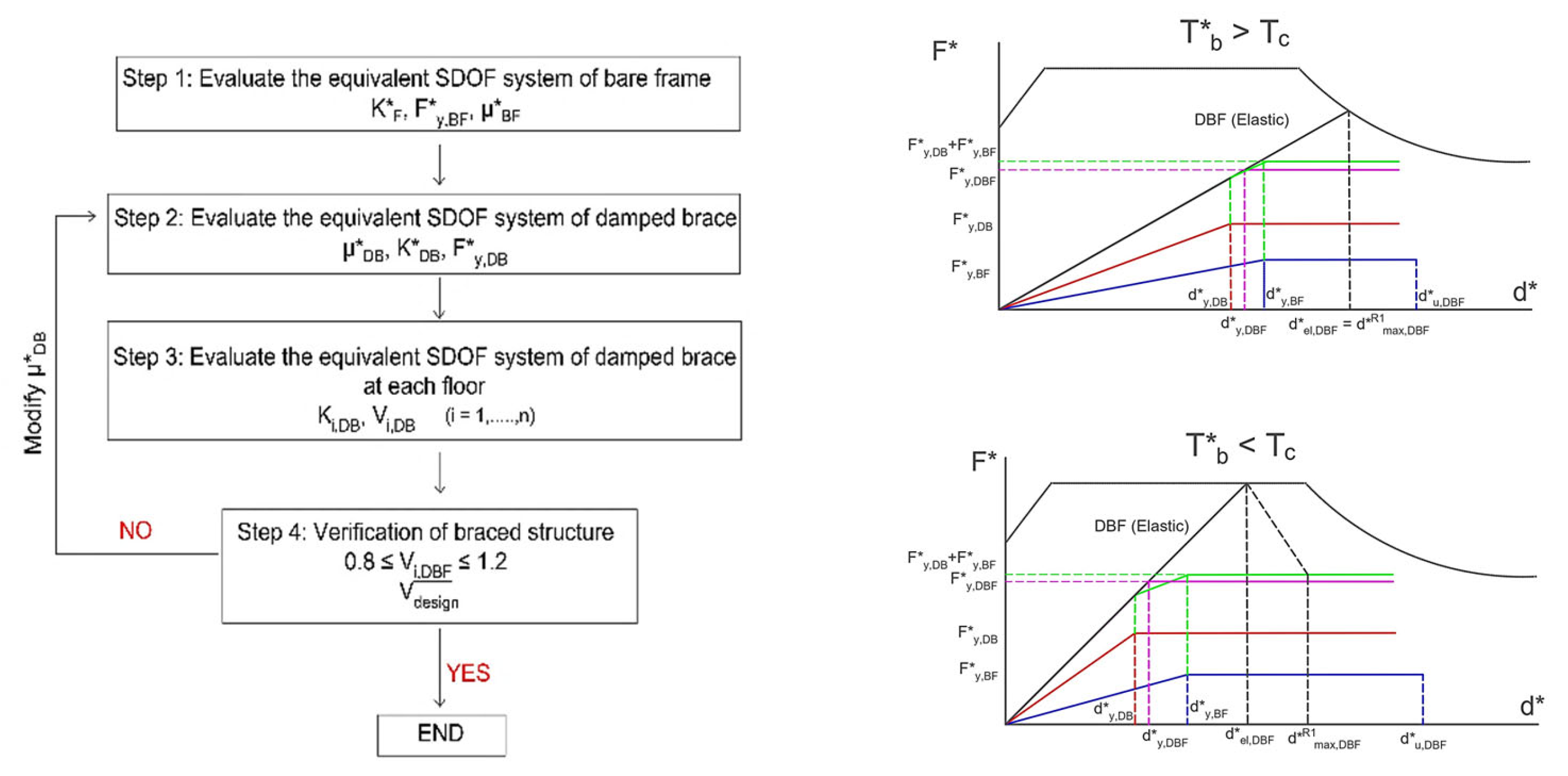
Figure 2.
BQC design method. a) Flowchart; b) Equivalent bilinear curve; c) Design method representation in the ADRS.
Figure 2.
BQC design method. a) Flowchart; b) Equivalent bilinear curve; c) Design method representation in the ADRS.
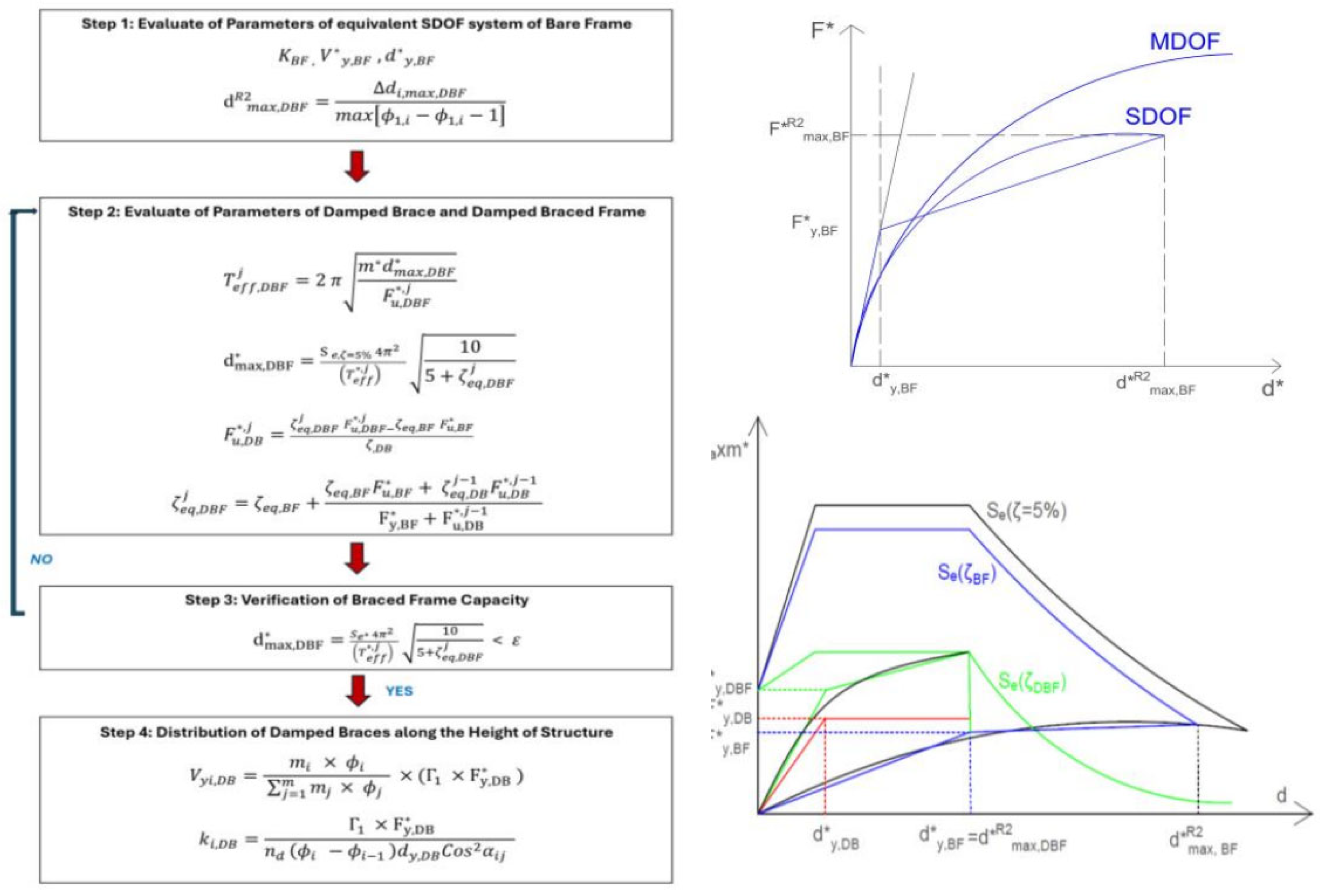
Figure 3.
Simplified (CAD) design method. a) Flowchart; b) ADRS representation.
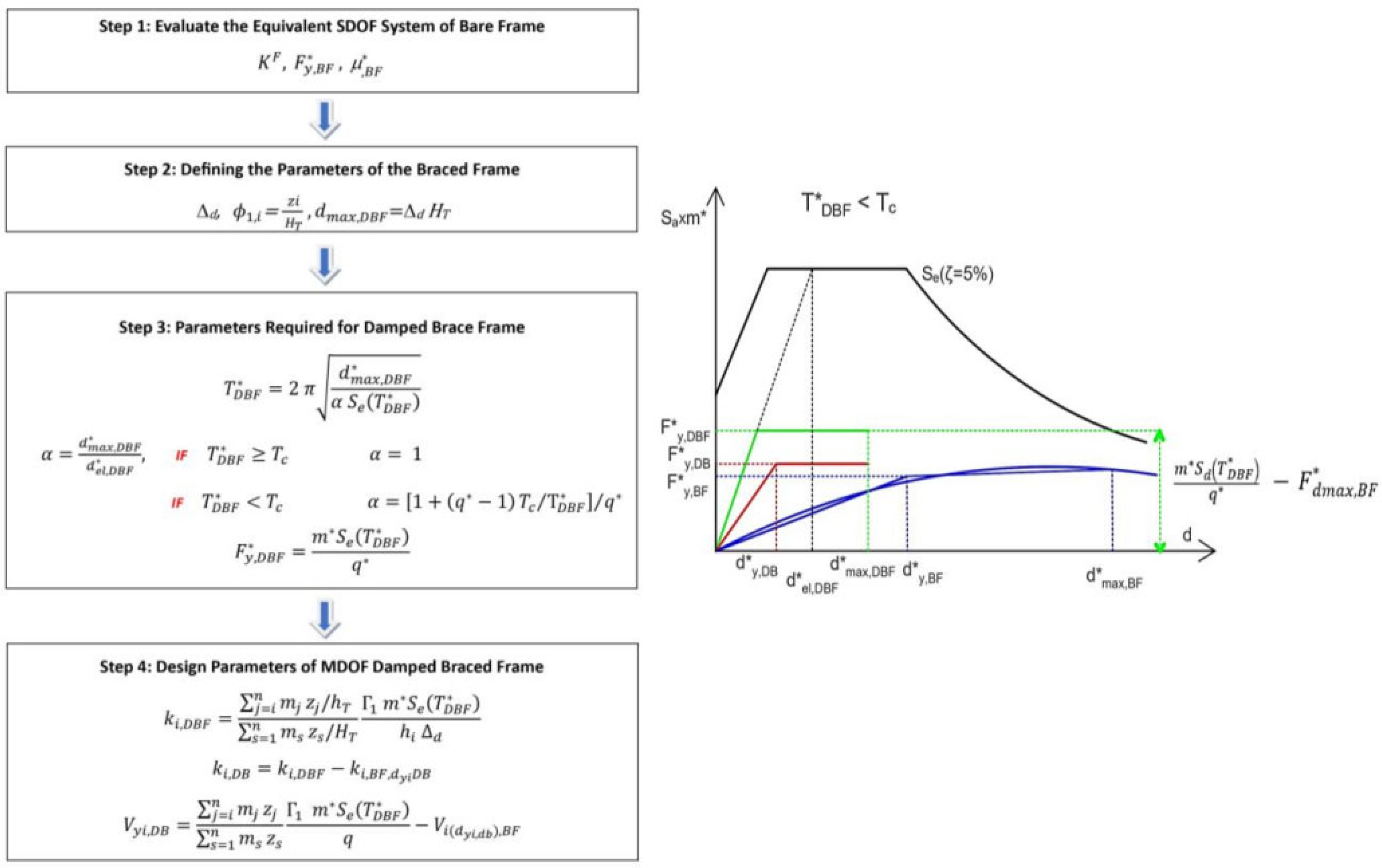
Figure 4.
Plan and section of: a) Bare frame (BF); b) Dissipative braced frame (DBF).
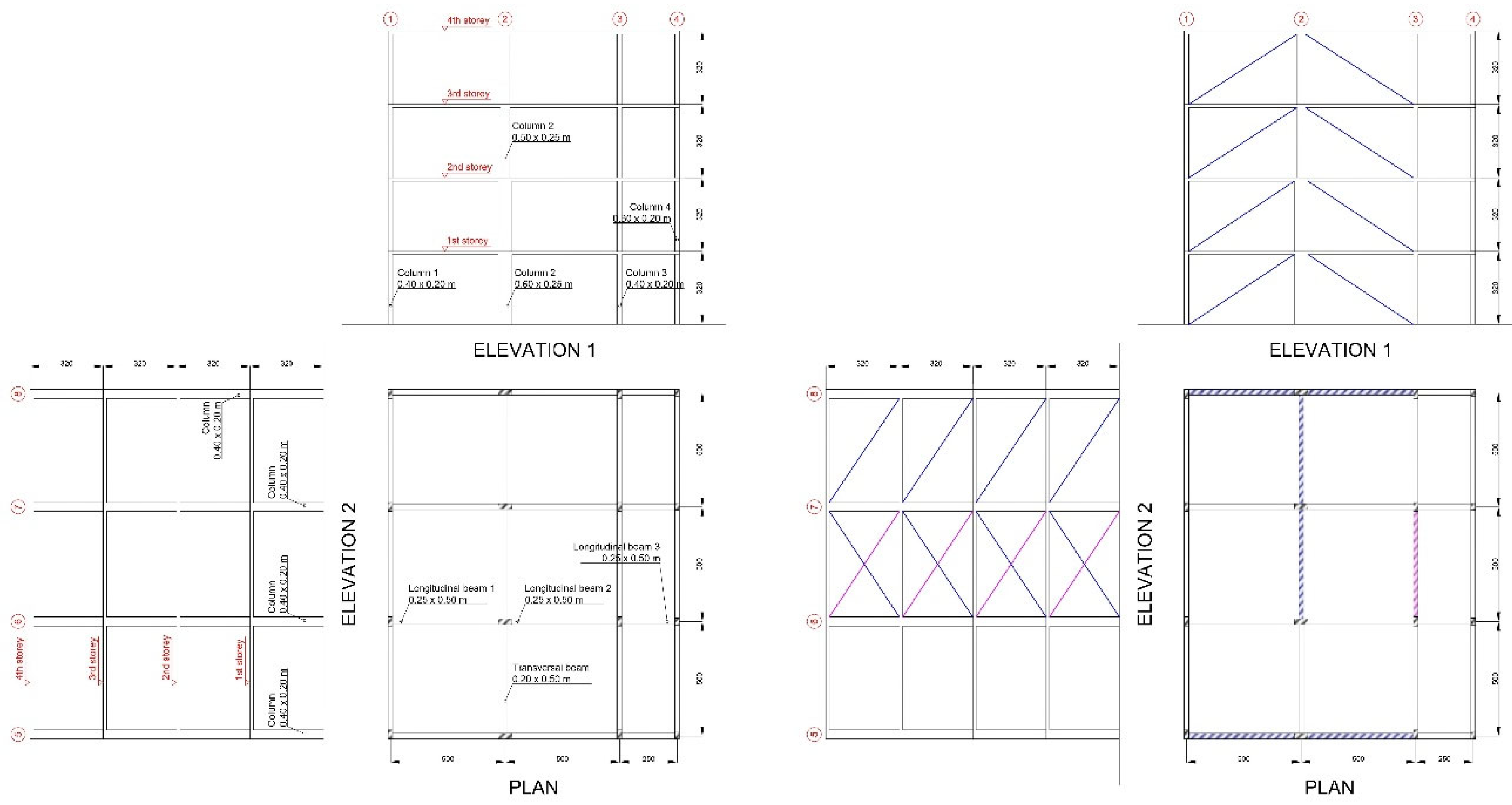
Figure 5.
Pushover curve of bare frame in a) x-direction; b) y-direction.
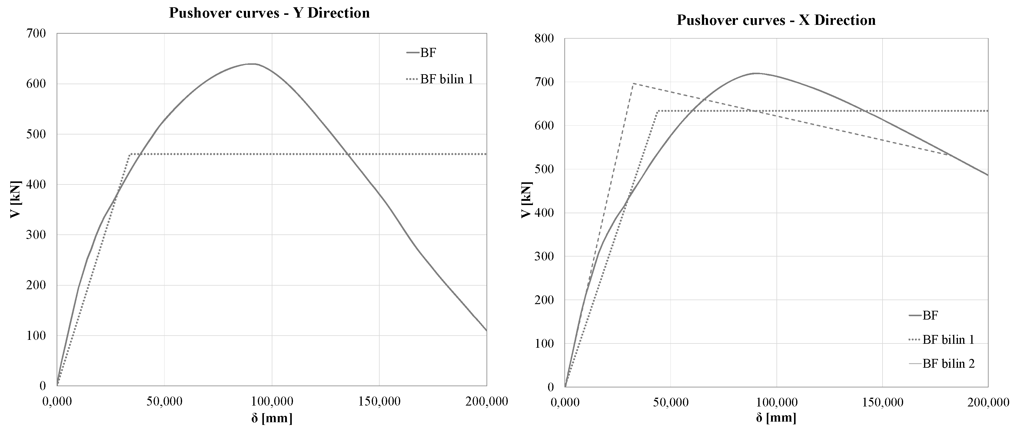
Figure 6.
Pushover curve of bare frame in a) x-direction; b) y-direction.
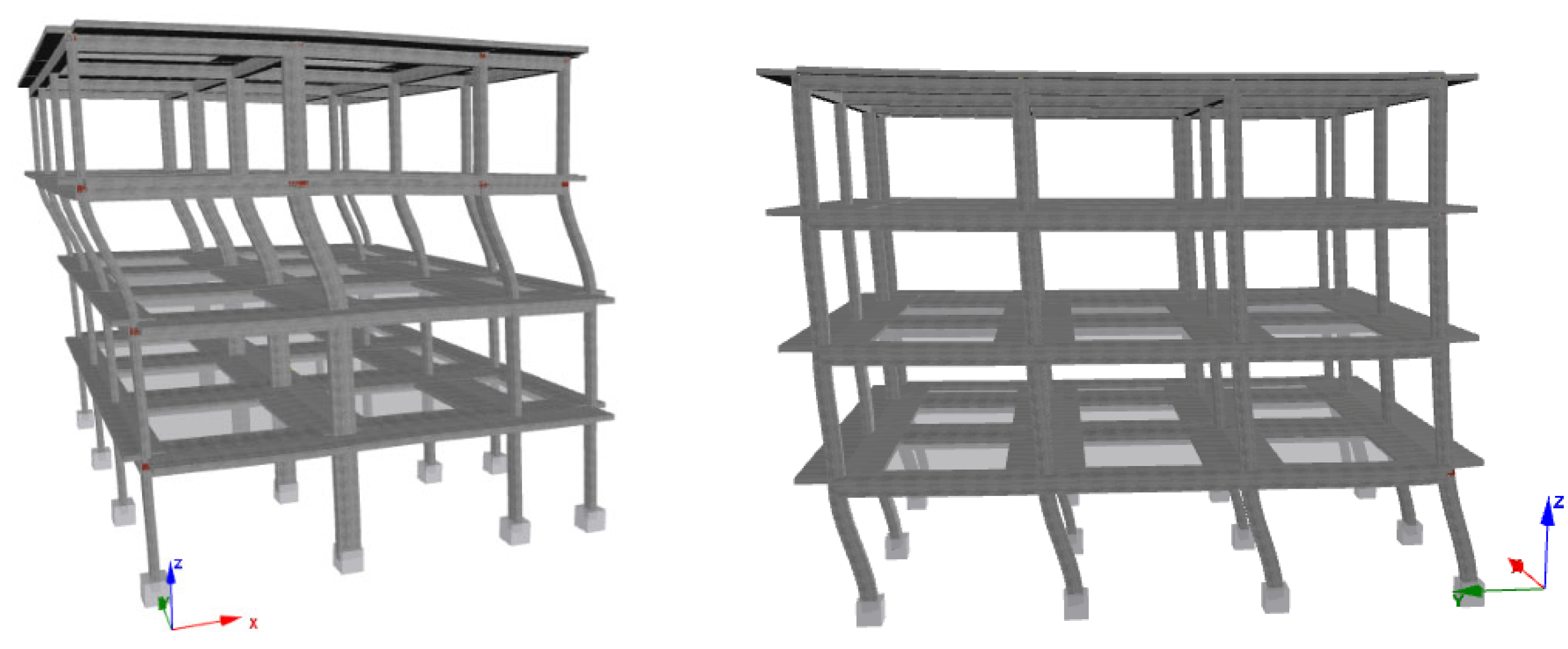
Figure 7.
Pushover curve of dissipative braced frames in a) x-direction; b) y-direction.
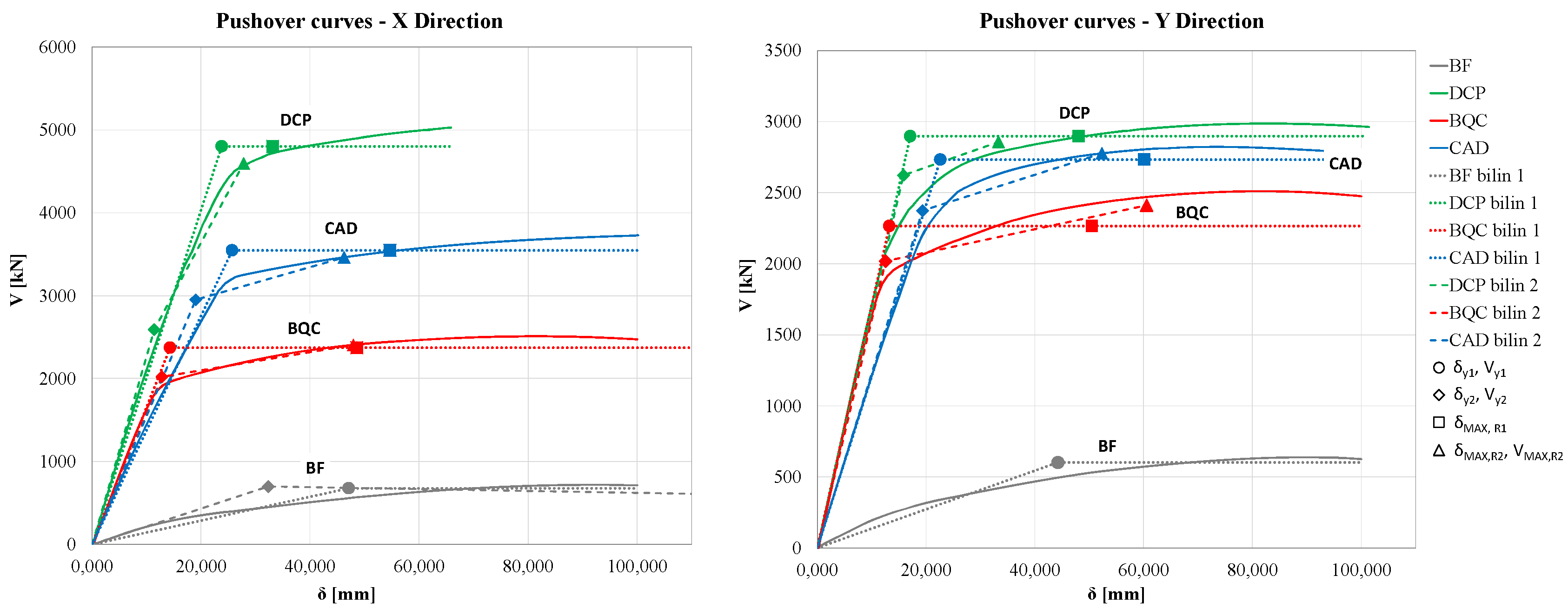
Figure 8.
Interstory drift assessment for dissipative braced frames by pushover analysis in a) x-direction; b) y-direction.
Figure 8.
Interstory drift assessment for dissipative braced frames by pushover analysis in a) x-direction; b) y-direction.
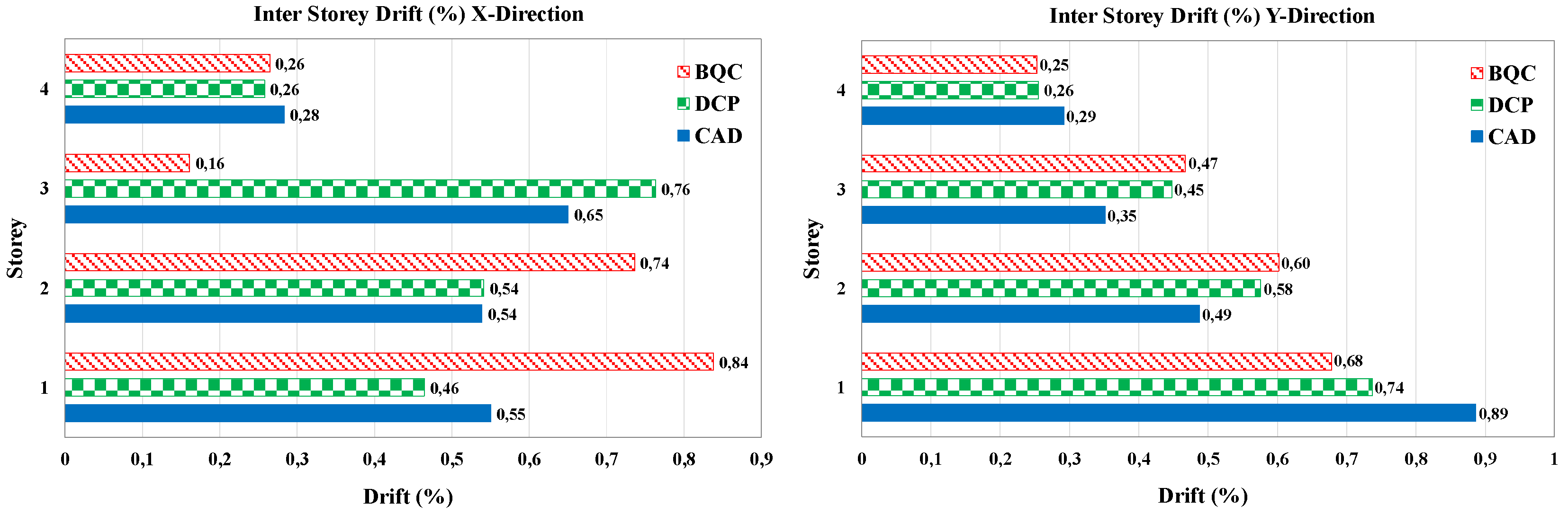
Figure 9.
Elastic response spectrum of the generated accelerograms vs target spectrum.
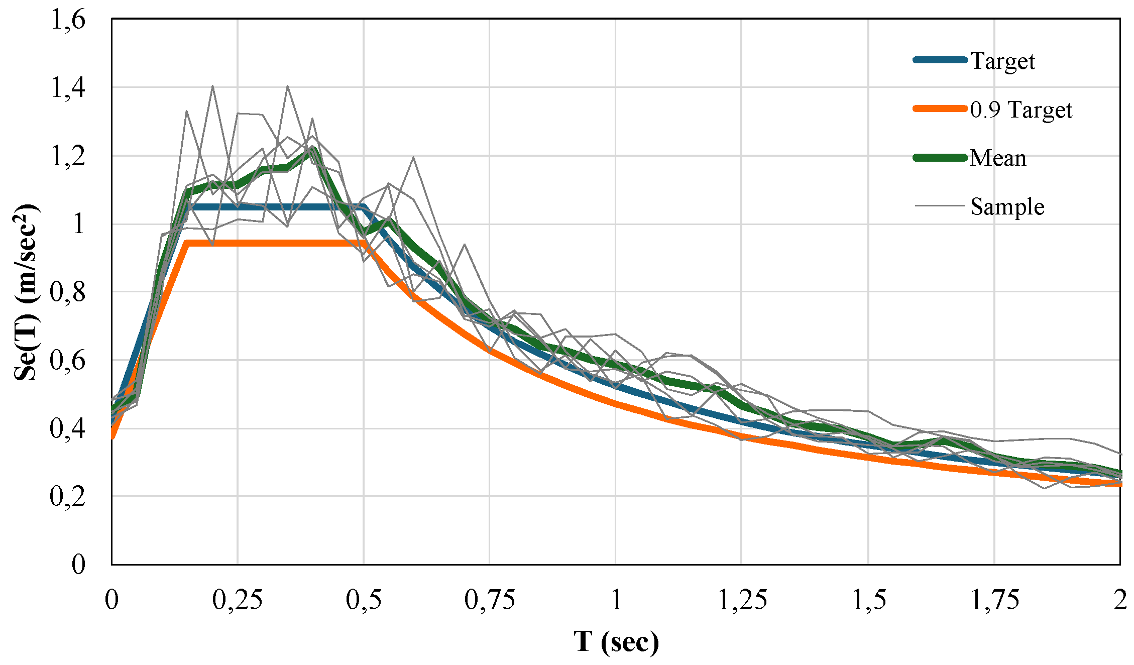
Figure 10.
Mean and maximum interstory drift for NLRHA for one directional input in x or y-direction.
Figure 10.
Mean and maximum interstory drift for NLRHA for one directional input in x or y-direction.
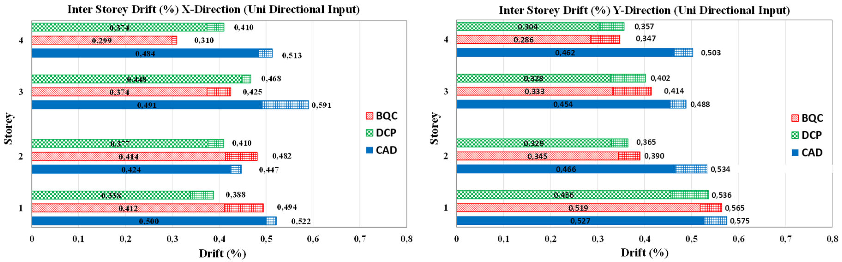
Figure 11.
Mean and maximum interstory drift in x or y-direction for NLRHA bidirectional input.
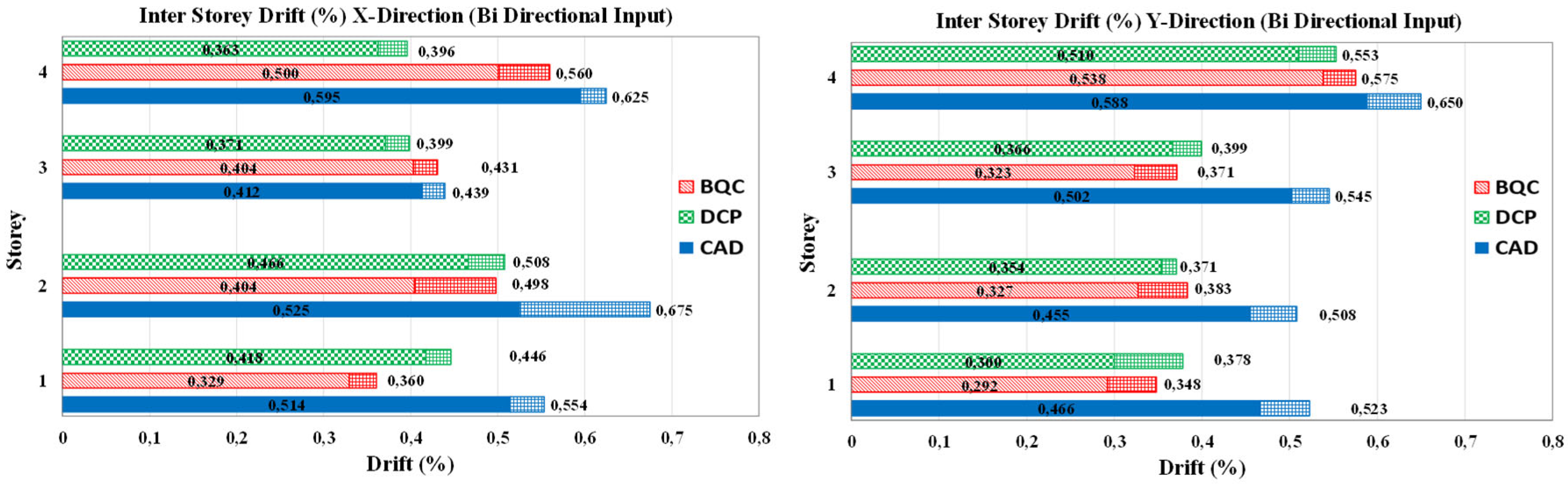

Table 1.
Details of cross section of the main structural elements.
| Longitudinal rebar (mm) | Transversal rebar | ||||||||
| Element | Cross sect mm x mm |
1st-2nd floor | 3rd-4th floor | End of elem. | Middle of elem. | ||||
| Column 1 | 400 x 200 | 6 ϕ 12 | 6 ϕ 2 | ϕ 6 / 15 | ϕ 6 / 15 | ||||
| Column 2 | 600 x 250 | 8 ϕ 16 + 2 ϕ 12 | 6 ϕ 16 + 2 ϕ 12 | ϕ 6 / 15 | ϕ 6 / 15 | ||||
| Column 3 | 400 x 200 | 8 ϕ 12 | 6 ϕ 12 | ϕ 6 / 15 | ϕ 6 / 15 | ||||
| Column 4 | 300 x 200 | 6 ϕ 12 | 6 ϕ 12 | ϕ 6 / 15 | ϕ 6 / 15 | ||||
| 1st-4th floor | |||||||||
| Section 1 | Middle | Section 2 | |||||||
| Top | Bottom | Top | Bottom | Top | Bottom | End of elem. | Middle of elem. | ||
| Longitudinal beam 1 | 250 x 500 | 2 ϕ 16 | 2 ϕ 16 | 2 ϕ 12 | 2 ϕ 12 + 2 ϕ 16 | 3 ϕ 16 | 2 ϕ 12 | ϕ 8 / 10 | ϕ 8 / 20 |
| Longitudinal beam 2 | 250 x 500 | 3 ϕ 16 | 2 ϕ 12 | 2 ϕ 12 | 2 ϕ 12 + 2 ϕ 16 | 2 ϕ 16 | 2 ϕ 16 + 2 ϕ 12 | ϕ 8 / 10 | ϕ 8 / 20 |
| Longitudinal beam 3 | 250 x 500 | 2 ϕ 16 | 2 ϕ 12 | 2 ϕ 12 | 2 ϕ 12 | 2 ϕ 12 | 3 ϕ 12 | ϕ 8 / 20 | ϕ 8 / 20 |
| Transversal beam | 200 x 500 | 4 ϕ 16 | 2 ϕ 12 | 4 ϕ 16 | 2 ϕ 12 | 4 ϕ 16 | 2 ϕ 12 | ϕ 8 / 10 | ϕ 8 / 10 |
Table 2.
Characteristics of the equivalent MDOF system of the bare frame according to the two different bilinearization procedures; j=EDR1, ED2;
Table 2.
Characteristics of the equivalent MDOF system of the bare frame according to the two different bilinearization procedures; j=EDR1, ED2;
| BF | ||||||
| PROCEDURE-dir | (kN/mm) | (mm) | (kN) | (mm) | (kN) | (sec) |
| EDR1-x | 14.39 | 44,1 | 633 | 194 | 633 | 1.16 |
| ED2-x | 7.44 | 32.3 | 697 | 183 | 530 | 2.53 |
| EDR1-y | 13.59 | 33,9 | 460 | 202 | 460 | 1.23 |
| ED2-y | * | * | * | >220 | * | * |
Table 3.
Stiffness and sliding forces of the bracing DB for the three design methods.
| Direction X | Direction Y | |||||||||
| Story | Story height hi(m) | Seismic weigth(kN) | (kN/mm) | (%) | (kN) | (mm) | (kN/mm) | (%) | dyi,BF(mm) | |
| 1st | 3.2 | 1844 | 52.89 | 0.889 | 846 | 16.0 | 43.15 | 0.923 | 710 | 9.79 |
| 2nd | 6.4 | 1844 | 47.01 | 0.685 | 636 | 13.5 | 37.67 | 0.860 | 613 | 16.2 |
| 3th | 9.6 | 1844 | 32.23 | 0.872 | 434 | 13.5 | 32.41 | 0.873 | 525 | 16.3 |
| 4th | 12.8 | 1881 | 28.11 | 327 | 11.6 | 30.09 | 294 | 16.5 | ||
Table 4.
Stiffness and sliding forces of the bracing DB for the three design methods.
| DPC | BQC | CAD | ||||||||||
| Story | (Kn/mm) | (kN) | (Kn/mm) | (kN) | (Kn/mm) | (kN) | (Kn/mm) | (kN) | (Kn/mm) | (kN) | (Kn/mm) | (kN) |
| 1st | 905 | 2404 | 687 | 2427 | 779 | 1693 | 655 | 1779 | 440 | 2104 | 480 | 2200 |
| 2nd | 629 | 2183 | 585 | 2160 | 542 | 1538 | 558 | 1583 | 395 | 1976 | 433 | 2035 |
| 3th | 509 | 1686 | 556 | 1625 | 438 | 1187 | 530 | 1191 | 312 | 1545 | 333 | 1547 |
| 4th | 492 | 919 | 536 | 873 | 424 | 647 | 511 | 640 | 169 | 835 | 179 | 834 |
Table 5.
Characteristics of the equivalent DBF-MDOF system for different design and bilinearization procedures.
Table 5.
Characteristics of the equivalent DBF-MDOF system for different design and bilinearization procedures.
| DPC | BQC | CAD | ||||||||||
| Des. PROC | EDR1-x | ED2-x | EDR1-y | ED2-y | EDR1-x | ED2-x | EDR1-y | ED2-y | EDR1-x | ED2-x | EDR1-y | ED2-y |
| (kN/mm) | 202 | 165 | 169 | 85.7 | 166 | 50,2 | 170 | 39.8 | 138 | 74.9 | 121 | 53 |
| (kN) | 23.8 | 11.4 | 17.1 | 15.8 | 14.3 | 12.8 | 13.2 | 12.6 | 25.7 | 19,0 | 22.7 | 19.3 |
| (kN/mm) | 4800 | 2592 | 2896 | 2622 | 2372 | 2023 | 2264 | 2017 | 3547 | 2952 | 2733 | 2373 |
| (mm) | 33,1 | 27.8 | 48,0 | 33.3 | 48.6 | 48.0 | 50.5 | 60.6 | 54.6 | 46.2 | 60.1 | 52.3 |
| (kN) | 4800 | 4594 | 2896 | 2856 | 2372 | 2406 | 2264 | 2409 | 3547 | 3463 | 2733 | 2776 |
| (sec) | 0.31 | 0.34 | 0.35 | 0.53 | 0.34 | 0.62 | 0.35 | 0.61 | 0.36 | 0.51 | 0.39 | 0.61 |
Table 6.
Mean and maximum total and interstory drift for NLRHA for one directional input in x or y-direction.
Table 6.
Mean and maximum total and interstory drift for NLRHA for one directional input in x or y-direction.
| Drift in x-direction | Drift in y-direction | ||||||||||||
| DCP | BQC | CAD | DCP | BQC | CAD | ||||||||
| Story | Mean | Max | Mean | Max | Mean | Max | Mean | Max | Mean | Max | Mean | Max | |
| Total | 0.36 | 0.37 | 0.36 | 0.40 | 0.42 | 0.45 | 0.34 | 0.37 | 0.34 | 0.38 | 0.44 | 0.50 | |
| Interstory drift | 4 | 0.37 | 0.41 | 0.30 | 0.31 | 0.48 | 0.51 | 0.30 | 0.36 | 0.29 | 0.35 | 0.46 | 0.50 |
| 3 | 0.45 | 0.47 | 0.37 | 0.42 | 0.49 | 0.59 | 0.33 | 0.40 | 0.33 | 0.41 | 0.45 | 0.49 | |
| 2 | 0.38 | 0.41 | 0.41 | 0.48 | 0.42 | 0.45 | 0.33 | 0.36 | 0.34 | 0.39 | 0.47 | 0.53 | |
| 1 | 0.34 | 0.39 | 0.41 | 0.49 | 0.50 | 0.52 | 0.46 | 0.54 | 0.52 | 0.56 | 0.53 | 0.58 | |
| Mean | 0.38 | 0.42 | 0.37 | 0.43 | 0.47 | 0.52 | 0.35 | 0.42 | 0.37 | 0.43 | 0.48 | 0.53 | |
| COV % | 12.0 | 8.1 | 14.3 | 19.7 | 7.2 | 11.3 | 19.5 | 20.1 | 27.6 | 22.0 | 7.1 | 7.3 | |
| Max | 0.45 | 0.47 | 0.41 | 0.49 | 0.50 | 0.59 | 0.46 | 0.54 | 0.52 | 0.56 | 0.53 | 0.58 | |
| Min | 0.34 | 0.39 | 0.30 | 0.31 | 0.42 | 0.45 | 0.30 | 0.36 | 0.29 | 0.35 | 0.45 | 0.49 | |
Table 7.
Mean and maximum total and interstory drift in x or y-direction for NLRHA for bidirectional input.
Table 7.
Mean and maximum total and interstory drift in x or y-direction for NLRHA for bidirectional input.
| Drift in x-direction | Drift in y-direction | ||||||||||||
| DCP | BQC | CAD | DCP | BQC | CAD | ||||||||
| story | Mean | Max | Mean | Max | Mean | Max | Mean | Max | Mean | Max | Mean | Max | |
| Total | 0.38 | 0.40 | 0.37 | 0.39 | 0.46 | 0.62 | 0.36 | 0.38 | 0.33 | 0.37 | 0.46 | 0.49 | |
| Interstory drift | 4 | 0.42 | 0.45 | 0.33 | 0.36 | 0.51 | 0.55 | 0.51 | 0.55 | 0.54 | 0.58 | 0.59 | 0.65 |
| 3 | 0.47 | 0.51 | 0.40 | 0.50 | 0.52 | 0.67 | 0.37 | 0.40 | 0.32 | 0.37 | 0.50 | 0.55 | |
| 2 | 0.37 | 0.40 | 0.40 | 0.43 | 0.41 | 0.44 | 0.35 | 0.37 | 0.33 | 0.38 | 0.46 | 0.51 | |
| 1 | 0.36 | 0.40 | 0.50 | 0.56 | 0.60 | 0.62 | 0.30 | 0.38 | 0.29 | 0.35 | 0.47 | 0.52 | |
| Mean | 0.40 | 0.44 | 0.41 | 0.46 | 0.51 | 0.57 | 0.38 | 0.43 | 0.37 | 0.42 | 0.50 | 0.56 | |
| COV % | 0.12 | 0.12 | 0.17 | 0.19 | 0.15 | 0.18 | 0.23 | 0.20 | 0.31 | 0.25 | 0.12 | 0.12 | |
| Max | 0.47 | 0.51 | 0.50 | 0.56 | 0.60 | 0.67 | 0.51 | 0.55 | 0.54 | 0.58 | 0.59 | 0.65 | |
| Min | 0.36 | 0.40 | 0.33 | 0.36 | 0.41 | 0.44 | 0.30 | 0.37 | 0.29 | 0.35 | 0.46 | 0.51 | |
Disclaimer/Publisher’s Note: The statements, opinions and data contained in all publications are solely those of the individual author(s) and contributor(s) and not of MDPI and/or the editor(s). MDPI and/or the editor(s) disclaim responsibility for any injury to people or property resulting from any ideas, methods, instructions or products referred to in the content. |
© 2024 by the authors. Licensee MDPI, Basel, Switzerland. This article is an open access article distributed under the terms and conditions of the Creative Commons Attribution (CC BY) license (https://creativecommons.org/licenses/by/4.0/).
Copyright: This open access article is published under a Creative Commons CC BY 4.0 license, which permit the free download, distribution, and reuse, provided that the author and preprint are cited in any reuse.


