
Submitted:
16 July 2024
Posted:
17 July 2024
You are already at the latest version
Abstract
Ballistic helmets are individual armor equipment designed to protect a soldier's head from projectiles and fragments. Although very common, these helmets are responsible for several causalities due to their low ballistic resistance and large back face deformation to stop the projectile. Therefore, to enhance helmet performance, studies have focused on the development of new materials and new ballistic protection solutions. The purpose of this study was to develop and evaluate a new ballistic solution using thermoplastic-based matrices. The first matrix was based on high-density polyethylene (HDPE). The second matrix was based on HDPE modified with ex-foliated montmorillonite (MMT). The main manufacturing processes of a thermoplastic-based ballistic helmet are presented, along with its ballistic performance, according to the National Institute of Justice (NIJ) standard 0106.01 and an investigation of its failure mechanisms via a non-destructive technique. All the helmets resulted in level III-A ballistic protection. The postimpact helmets were scanned to evaluate the back face deformation dimensions, which revealed that the global cone deformation was deeper in the HDPE than in the HDPE/MMT. The failure analysis revealed an overall larger deformation area in the HDPE and HDPE/MMT helmet delamination zones in regions with a large radius of curvature than in zones with the lowest radius, which is in accordance with previous simulations from the literature.
Keywords:
thermoplastic composites
; ballistic helmet shells
; scanning
; computed tomography
1. Introduction
Ballistic helmets are individual armor equipment designed to protect the soldier’s head from projectiles and fragments, absorbing impact energy and minimizing their effects on the skull and brain [1]. The composite material currently used in ballistic helmet processing is para-aramid/PVB-phenolic, which was designed in the mid-1970s [2,3,4], with PASGT (Personal Armor System for Ground Troops) and ACH (Advanced Combat Helmet) being the most common helmets manufactured with those materials.
Numerous studies concerning ballistic helmets have used composite plates instead of helmet shells because plates are more suitable for sample cutting (to examine mechanical properties) and specific ballistic tests (namely, ballistic limit and back face deformation). This approach was previously followed by these authors [5,6]. Typically, para-aramid prepreg plates are processed by applying 1.4 MPa–2.5 MPa, 150 °C–170 °C and 60 minutes–90 minutes, whereas UHMWPE prepreg plates, such as Dyneema and Spec-traShield, require higher pressures (typically 13 MPa–40 MPa) and lower temperatures (120 °C–130 °C), with similar processing times [7,8,9,10,11]. Nevertheless, ballistic helmet processing is considerably more complex. In general, this process consists of stacking several prepregs and compressing them at controlled pressure and temperature into a hemispherical mold where the shell obtains the desired shape [2]. The basic processing parameters, pressure, temperature and time, vary according to a number factors. The critical factors include the amount of prepregs (which interferes with the desired thickness), fibers, resins and the fiber/resin ratio [12].
The main challenge in ballistic helmet shell manufacturing is obtaining a complex three-dimensional geometry, while the raw materials are flat form prepreg layers. To overcome this struggle, various layers cannot be placed in the press without some overlap, since this would generate wrinkles and voids in the shell, in addition to excess cut-out and, therefore, material losses [3]. To minimize flaws and reduce material waste, prepregs are designed and cut on preforms, which must have geometries that allow layers to uniformly overlap [13,14,15,16]. When researchers experiment with and develop new composite materials for ballistic helmets, they face the challenge of adapting their project to existing production methods or even creating new methods. Walsh, Scott and Spagnuolo [17] produced several carbon fiber/thermoset matrices (IM7 ®/epoxy)—aramid fiber/thermoplastic matrix (KM2 ®/polyolefin) hybridized ballistic plates. Although this approach presents a faster solution, coprocessing both parts demands that the resin curing cycle occurs at the same time and temperature of thermoplastic melting and consolidation. Researchers choose IM7 ®/epoxy and KM2 ®/polyolefin to manufacture shells. The same research group, Walsh et al. [18], compared the previous solution with numerous combinations of UHMWPE, para-aramid, glass and carbon fiber prepregs, applying V50 ballistic and cyclic quasistatic compression tests. The authors concluded that the KM2 ®/polyolefin–IM7 ®/epoxy hybrid composite shell still had superior results. Campbell and Kramer [19] adapted the traditional method to a thermoforming press to coprocess 39 layers of K49 ®/PU and an external layer of carbon fibers prepreg, AS4 ®/PPS. Prior to pressing, the prepregs were stacked and fixed in a shuttle frame and subjected to infrared heating so that the stacks could deform under pressure without tearing. The final solution resulted in high thickness variation and wrinkling. Marissen et al. [20] studied the use of the creep forming technique on Dyneema HB25 ®/ UHMWPE prepregs for the processing of ballistic helmet shells and studied several creep rates and temperatures. The authors adapted the traditional press using creep and shape frames to impose creep tension at the prepreg edges and heat guns to guarantee homogeneous temperature distribution at the shell, obtaining helmets free of wrinkles. Fejdýs et al. [21] coprocessed Dyneema HB80 and Teijin CT736 ®/PVB-phenolic prepregs in several compositions. The processing meth-od involves two phases: first, the aramid layers are pressed (which demands higher temperatures than polyethylene fibers can withstand), then the layers are copressed, after which the UHMWPE layers are prepressed. The authors reported that the 80% CT736 ®/PVB-phenolic and 20% Dyneema HB80 ® compositions presented superior results, combined with a 20% mass reduction compared with the common helmet material (100% CT736 ®/PVB-phenolic). Ning et al. [22] developed a helmet insert in which a carbon long-fiber thermoplastic (LFT) with a polyphenylene sulfide (PPS) matrix, LFT C/PPS, was used. The authors tested different insert drawings via finite element analysis (FEA) and produced one that added greater stiffness to the helmet shell. Ahn et al. [23] used thermo-hydroforming, a technique developed in 2003, to process a ballistic helmet using 180 layers of Spectra Shield SR-3136. Researchers have also implemented an explicit finite element code to simulate processing, predict possible wrinkle areas and adjust the production parameters to amend them.
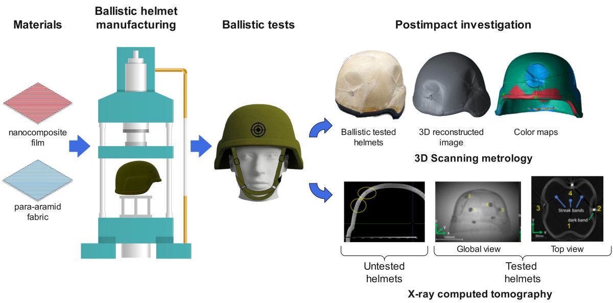
In this study, the performance of industrially manufactured fully equipped thermo-plastic-based ballistic helmets was evaluated according to the National Institute of Justice (NIJ) standard 0106.01. The ballistic protection solution was built with para-aramid plain-woven fabric and evaluated for two different matrices. The matrices were based on high-density polyethylene (HDPE) and HDPE modified with exfoliated montmorillonite (MMT). The scanning technique was applied to the helmets before and after impact to quantify the overall residual back face deformation. A nondestructive technique, X-ray computed tomography (CT), was employed to assess damage and delamination extension.
2. Materials and Methods
2.1. Materials
HDPE commercialized as AC59®, kindly supplied by Braskem (RJ, Brazil), was used as the matrix. Organophilic montmorillonite Cloisite 20A was purchased from Southern Clay Products (Gonzales, TX). A K129-type para-aramid plain-woven, kindly supplied by DuPont (SP, Brazil), was chosen to produce the preform layers. All materials were used without any previous treatment.
2.2. Ballistic Helmet Manufacturing
An FKL 200 ton heat press with a water-cooling system was used to process the helmet shells. An ACH mold was installed on the equipment. In the first minutes of pressure, after heating to 160 °C, a degassing procedure was used to remove air bubbles from the layers, minimizing manufacturing defects.
2.3. Ballistic Tests
The ballistic helmets were tested to evaluate their level of performance, applying ballistic Type III-A conditions according to NIJ 0106.01 [24], which consists of a ballistic test with 9 mm ammunition, which was conducted at a 5 m distance, within 358 ± 15 m/s of speed range, in a proper gunfire safety range. The ballistic helmets were trapped at a standard 6061-T6 aluminum head form and subjected to four shots (front, back, right and left sides).
2.4. 3D Scanning Metrology
To capture accurate deformation of the HDPE and HDPE/MMT helmets, 3D scanning measurements were performed before and after the ballistic tests, using a FARO Laser Line Probe, Model FAROBlu Xp, coupled to FARO Arm Quantum Max E, Model 41000. This device runs with FARO CAM2 v2023.9 software, which provides a point cloud with a set of data points in a coordinate system that accurately depicts the size, shape and details of the helmets.
To measure the dimensional variations in the helmet shell, for each helmet, the inner and outer shells were scanned before and after impact, and a point cloud was produced. The points for the two conditions and for each surface were superimposed. For each point, the displacement, ∆, in relation to the reference surface was calculated. For the outer shell, . If , there was no deformation. The scheme presented in Figure 1 shows the measurement of ∆.
A color map was generated from the deformation measurements. For , a green color was assigned. When , a blue color was assigned, and when , a red color was assigned. On the basis of the color map, the area surrounding the impact point, A, was obtained. To this end, A was approximated to a circle or an ellipse, choosing the geometric shape that ensured the best fit. The procedure was carried out for the outer surface and the inner surface of the shell.
2.5. X-ray Computed Tomography
The ballistic helmets were inspected with GE Micro Computed Tomography (CT) equipment, Phoenix/XS model, with a 240 kV microfocus X-ray source, achieving 10 µm of 3D spatial resolution. The sample was rotated at 0.5° steps through a rotation angle of 360°. Five frames were averaged for each image projection to improve the signal‒noise ratio of the final image; later, each CT image was evaluated and postprocessed with the commercial software Dragonfly. The impact region was analyzed in detail, and owing to the size of the damaged area and the contrast obtained, it was not necessary to apply dye-penetrating contrast. The tomographic inspection procedure followed ASTM E1742-18—“Standard Practice for Radiographic Examination” [25].
The helmet was visualized through an isometric and lateral view of the right side of the impacted area. Compared with the composite material, the bullet lodged in the helmet presented a high contrast result. This contrast difference generated some undesired artifacts in the final image and was carefully manipulated.
3. Results and Discussion
3.1. Ballistic Helmet Manufacturing
The HDPE and HDPE nanocomposite matrices were produced as films to fit the 88% fiber–12% matrix mass ratio used in ballistic helmet manufacturing. Initially, the films were produced by mixing and extruding the HDPE and the nanoparticles via a SEIBT® ES-35 single-screw extruder (diameter 16 mm, L/D = 26) at 40 rpm and 120 °C from the feed zone to die. Pellets with 0% and 3 wt% MMT were obtained and named HDPE and HDPE/MMT, respectively. The blown films were obtained from the pellets via the same ex-truder connected to a film blown annular die and film take-up device (D0 = 40 mm, L/D = 32) at 50 rpm and a temperature profile of 170 °C to 200 °C at three heating zones and at the annular die (Figure 2).
Further details concerning the nanocomposite composition and thermoplastic film processing can be found in the authors’ preceding studies [5,6].
The ballistic helmets were manufactured at Glagio de Brazil Company. Figure 3 presents the process flowchart.
The processing stages are summarized below:
- While the thermoplastic matrices were cut with ordinary scissors, the K129 aramid fabric was cut using a Lectra VectorFX mechanical cutting machine.
- The fiber and matrix preforms were stacked one by one manually. Twenty-four layers of fiber and matrix were employed to produce a single ballistic helmet.
- Two different assemblies were studied: HDPE: stacking the 24 layers of fiber and HDPE matrix; and HDPE/MMT: stacking the 24 layers of fibers and the HDPE/MMT matrix;
- An FKL 200 ton heat press with a water-cooling system was used to process the helmet shells. The equipment has an ACH mold installed, as shown in Figure 4(a), and the 24 preform layers are placed on the mold, as shown in Figure 4(b), which produces an item with surplus material, as shown in Figure 4(c).
- The temperature and force applied are summarized in Figure 5. A degassing procedure was used to remove air bubbles from the layers, minimizing manufacturing defects.
- After heating, the rubber and pads are glued to the shell manually. The chin piece is connected to the shell through four drill holes. The thermoplastic-based ballistic helmets were then ready for testing.
3.2. Ballistic Tests
Table 1 summarizes the ballistic results. In Table 1, NP means no penetration, where-as NIJ 0106.01 means perforation of a witness plate by any part of the test specimen or test bullet, as determined by the passage of light when the witness plate is held up to a 60-W light bulb. Therefore, all the helmets achieved Level III-A ballistic performance.
Figure 6 presents the impact position.
The ballistic results and material responses are influenced by the shoot sequence, hit position and helmet design. The last impact will face a composite with larger delimitation areas and less structural steadiness than the first impact point, which will impose less efficient barriers to prevent the spread of the projectile. Moreover, the chamfers and ripples present on the edge and sides of the helmet or even its orbicular shape prevent impact at 0°, resulting in a less efficient hit. Because the NIJ standard does not establish a back face deformation assessment, after ballistic tests, the deformation areas were obtained throughout the scanning procedure.
3.3. 3D Scanning Metrology
Figure 7 shows the 3D reconstructed images of the HDPE/MMT helmets compared with the original images. The size, shape and details were accurately depicted.
Figure 8 shows color maps of the dimensional deviations.
Figure 8 shows that the green color represents regions that were not affected by the impact of the projectile. On the outer shell of the external surface, the blue color represents the indentation caused by the impact, which generates, on the internal surface of the helmet, the protruding region, represented by the red color, which is usually referred to as the back face deformation. Figure 8 shows the maximum depth of the indented region, the maximum height of the protruding region, the approximate area of the indented surface and the area of the protruding surface. Finally, in Figure 8, for demonstration purposes, the diameter of the circle is observed if the region has been approximated to a circle, or the major axis and the minor axis of the ellipse if the region has been approximated to an ellipse. Table 2 summarizes the results obtained via the 3D scanning metrology method.
To facilitate visualization, the data was described in graphs in Figure 9.
As shown in Figure 9(a), compared with the HDPE helmet, the HDPE/MMT system is susceptible to a smaller D in the inner shell and greater D in the outer shell. These results suggest that the deformation in the direction of impact for the HDPE/MMT system is transferred radially and occurs between the internal layers. However, the deformed area values presented in Figure 9(b) are random, and it is not clear whether the deformed area is great-er for the system with nanoparticles; this suggests that the mechanism for dispersing the impact energy is not the stretching of the fibers and the composite matrix but rather the processes related to the delamination mechanisms. As observed, greater displacement was observed for the back-side impact where the target was impacted at approximately 0° and no edge or chamfer was present.
3.3. X-ray Computed Tomography
Figure 10 shows the planes of the undeformed HDPE and HDPE/MMT helmets. Non-destructive testing revealed an overall very good composite manufacturing quality, even when the stacking process was used instead of prepregs. Nevertheless, Figure 11 high-lights regions of void manufacturing failure in each composition. The position of these defects is in the curvature that joins the parietal and frontal parts of the helmet (the 45-degree corner).
Figure 11 and Figure 12 show the tomography images of the HDPE and HDPE/MMT helmets after the ballistic test, respectively, revealing the damaged region. Delamination, the major energy-absorbing mechanism during the impact of the laminate composite, was observed in all the cases. The beginning and end of extensive delamination areas are de-noted by short yellow arrows in the images. To improve the visualization of delaminations, slices slightly above or below the impact point were selected in Figure 11 and Figure 12 (b, c, e, and f). Figures 11(d) and 12(d) show the back face deformation for both helmets.
The results presented in Figure 11 and Figure 12 agree well with the scanned measurement results, showing that the outer shell, external surface, and displacement are significantly smaller than those of the inner shell. Comparatively, as shown in Figure 12 and Figure 13, the back face deformation of the HDPE was greater than that of the HDPE/MMT, which was previously measured in Figure 9 and Table 2. The damage in this region was caused by delaminations and fractures of the aramid plain-woven layers. Between 6 and 11 layers were penetrated on the HDPE helmet, and between 4 and 7 layers were penetrated for the HDPE/MMT. This finding indicates that the ammunition kinetic energy was ab-sorbed through mechanisms other than fiber rupture/delamination. Considering the great-er deformed area observed in Figure 9 and in Table 2, it is possible to infer that this result is because the ability of the HDPE/MMT matrix to disperse energy radially is greater than that of the HDPE.
Figure 12(e) shows that an extensive delamination area is observed in the HDPE/MMT helmet frontal impact, which explains the greater displacement, D = 15.9 mm, for the outer shell. The delaminations in regions with a large radius of curvature were larger than those in regions with the lowest radius. Similar conclusions were obtained by [27] via finite element and analytical studies on graphite‒epoxy curved beams. Streak bands are shown on several slides of the helmets, as shown in Figure 11(d). The bands are localized near the projectiles embedded in the impacted zone; these are a consequence of the high density of the bullet (lead alloy) surrounded by the low density of thermoplastic matrices [26]. The projectile density exceeded the measurement range of the tomograph and produced these artifacts. The dark regions near the bullets are called dark bands and can be observed in Figure 11(d) and Figure 12(d); this is an artifact that originates from X-ray beam hardening due to the presence of high-density materials [27,28,29].
4. Conclusions
Thermoplastic ballistic helmets were produced via HDPE and HDPE/MMT matrices, adapting the helmet production method to thermoplastic stacking instead of thermoset prepregs. The ballistic test resulted in level III-A ballistic protection. The scanning procedure revealed that the HDPE/MMT helmet resulted in less residual back face deformation and a greater impact absorption area than did the HDPE. X-ray tomography of nonimpact helmets revealed very good overall manufacturing quality, although small regions of voids could be observed on the limit region of the parietal and frontal regions of the shell. Computed tomography allowed the characterization of internal damage in the HDPE and HDPE/MMT helmets. The impacted tomography imaging revealed that delaminations in regions with a large radius of curvature were larger than those in zones with the lowest radius, in accordance with previous simulations from the literature. The main failure mechanism in both helmets was delamination. With respect to layer perforation, the HDPE/MMT was more efficient, with fewer average layers penetrated and a greater area of impact absorption, allowing a consistent decrease in deformation.
6. Patents
The composites listed above are files for patents. The files were submitted to the National Institute of Intellectual Property (INPI) in Brazil.
Supplementary Materials
The following supporting information can be downloaded at the website of this paper posted on Preprints.org, Figure S1: title; Table S1: title; Video S1: title.
Author Contributions
Author 1: Conceptualization; Methodology; Formal Analysis; Writing—original draft. Author 2: Conceptualization and methodology of scanning metrology. Author 3-4: Conceptualization, Methodology and Formal Analysis of X-ray Computer Tomography; Author 5: Resources; Supervision; Writing—review.
Funding
This study was financially supported by the Financiadora de Estudos e Projetos (FINEP)—Reference 1636/22 Contract 01.22.0546.00.
Data Availability Statement
The original contributions presented in the study are included in the article/supplementary ma-terial, and further inquiries can be directed to the corresponding author/s.
Acknowledgments
The authors are grateful to Glagio do Brazil industry for supporting helmet manufacturing.
Conflicts of Interest
The authors declare no conflicts of interest.
References
- Laible RC (2012) Ballistic Materials and Penetration Mechanics. Vol 5. Elsevier, Netherlands.
- Kulkarni SG, Gao XL, Horner SE, Zheng JQ, David NV (2013) Ballistic helmets – Their design, materials, and performance against traumatic brain injury. Compos Struct. 101:313-331. [CrossRef]
- Hamouda AMS, Sohaimi RM, Zaidi AMA, Abdullah S (2012) Materials and design issues for military helmets. In: Sparks E, ed. Advances in Military Textiles and Personal Equipment. 1st edn. Elsevier, Netherlands pp: 103-138. [CrossRef]
- Liang Y, Chen X, Soutis C (2022) Review on Manufacture of Military Composite Helmet. Appl Compos Mater 29(1):305-323. [CrossRef]
- Dias RR, Zattera AJ, Pereira IM, Soares BG (2021) Ballistic impact performance of composite laminates based on high-density polyethylene/montmorillonite nanocomposite and Aramide fiber. Polym Compos 42(10):5586-5597. [CrossRef]
- de Tomasi Tessari B, Vargas N, Rodrigues Dias R, et al. (2022) Influence of the addition of graphene nanoplatelets on the ballistic properties of HDPE/aramid multi-laminar composites. Polym-Plast Technol Mater 61(4):363-373. [CrossRef]
- Vargas-Gonzalez L, Walsh SM, Wolbert J (2011) Impact and Ballistic Response of Hybridized Thermoplastic Laminates. U.S. Army Research Laboratory Report ARL-MR-0769.
- Freitas CJ, Bigger RP, Grimm M v, Mackiewicz J. Resin/Fabric Composites Dynamic Back Face Deflection Characteristics due to Ballistic Impact (2014) In: CAMX Conference Proceedings. Composites and Advanced Materials Expo pp 1-14.
- Sapozhnikov SB, Kudryavtsev OA, Zhikharev MV (2015) Fragment ballistic performance of homogenous and hybrid thermoplastic composites. Int J Impact Eng 81:8-16. [CrossRef]
- Vargas-Gonzalez LR, Gurganus JC (2015) Hybridized composite architecture for mitigation of non-penetrating ballistic trauma. Int J Impact Eng. 86:295-306. [CrossRef]
- Zhang TG, Satapathy SS, Vargas-Gonzalez LR, Walsh SM (2015) Ballistic impact response of Ultra-High-Molecular-Weight Polyethylene (UHMWPE). Compos Struct 133:191-201. [CrossRef]
- Bhatnagar A (2006) Lightweight Ballistic Composites Military and Law-Enforcement Applications. Elsevier, Netherlands.
- Cunniff, Parker (2018) The Effect of Preform Shape on Ballistic Impact Performance, Coverage and Seam Density in Combat Helmets. In: Proceedings of 24th International Symposium on Ballistics.
- Grick SJ (1983) Helmet shell fabric layer and method of making the same. U.S. Patent Documents U.S. US4596056A.
- White MR (1988) Ballistic helmet body. U.S. Patent Documents U.S. US4908877A.
- Hanks JA, West BC, McMinn JH. Composite material: a ballistic resistant article made from same and method of making the article. U.S. Patent Documents U.S. US20130095716A1.
- Walsh SM, Scott BR, Spagnuolo DM (2005) The Development of a Hybrid Thermoplastic Ballistic Material with Application to Helmets. U.S. Army Research Laboratory Report ARL-TR-3700.
- Walsh SM, Scott BR, Spagnuolo DM, Wolbert JP (2006) Hybridized Thermoplastic Aramids: Enabling Material Technology for Future Force Headgear U.S. Army Research Laboratory Report.
- Campbell DT, Cramer DR (2008) Hybrid Thermoplastic Composite Ballistic Helmet Fabrication Study. Adv. Mater. Process Eng.
- Marissen R, Duurkoop D, Hoefnagels H, Bergsma OK (2010) Creep forming of high strength polyethylene fiber prepregs for the production of ballistic protection helmets. Compos Sci Technol 70(7):1184-1188. [CrossRef]
- Fejdyś M, Łandwijt M, Habaj W, Struszczyk MH (2015) Ballistic Helmet Development Using UHMWPE Fibrous Materials. FIBRES & TEXTILES in Eastern. Fibres Text East Eur 23(109):89-97.
- Ning H, Pillay S, Thattaiparthasarathy KB, Vaidya UK (2017) Design and manufacturing of long fiber thermoplastic composite helmet insert. Compos Struct 168:792-797. [CrossRef]
- Ahn H, Kuuttila NE, Pourboghrat F (2018) Mechanical analysis of thermo-hydroforming of a fiber-reinforced thermoplastic composite helmet using preferred fiber orientation model. J Compos Mater. 2018;52(23):3183-3198. [CrossRef]
- National Institute of Justice Standard NIJ-STD 0106.01. Standard for Ballistic Helmets. Published online 1981:1-16.. https://www.ojp.gov/pdffiles1/nij/077182.pdf Accessed December 13, 2022.
- ASTM Standard E1742/E1742M-18. Standard Practice for Radiographic Examination. Published online 2018:1-17. [CrossRef]
- Nguyen T (2010) Effects of Curvature on the Stresses of a Curved Laminated Beams Subjected to Bending. Dissertation, University of Texas.
- Sause MGR. Computed Tomography. In: In Situ Monitoring of Fiber-Reinforced Composites. Springer Germany pp 457-532. [CrossRef]
- Maire E, Withers PJ (2014) Quantitative X-ray tomography. Int Mater Rev 59(1):1-43. [CrossRef]
- Garcea SC, Wang Y, Withers PJ (2018) X-ray computed tomography of polymer composites. Compos Sci Technol 156:305-319. [CrossRef]
Figure 1.
This is a figure. Schemes follow the same formatting.
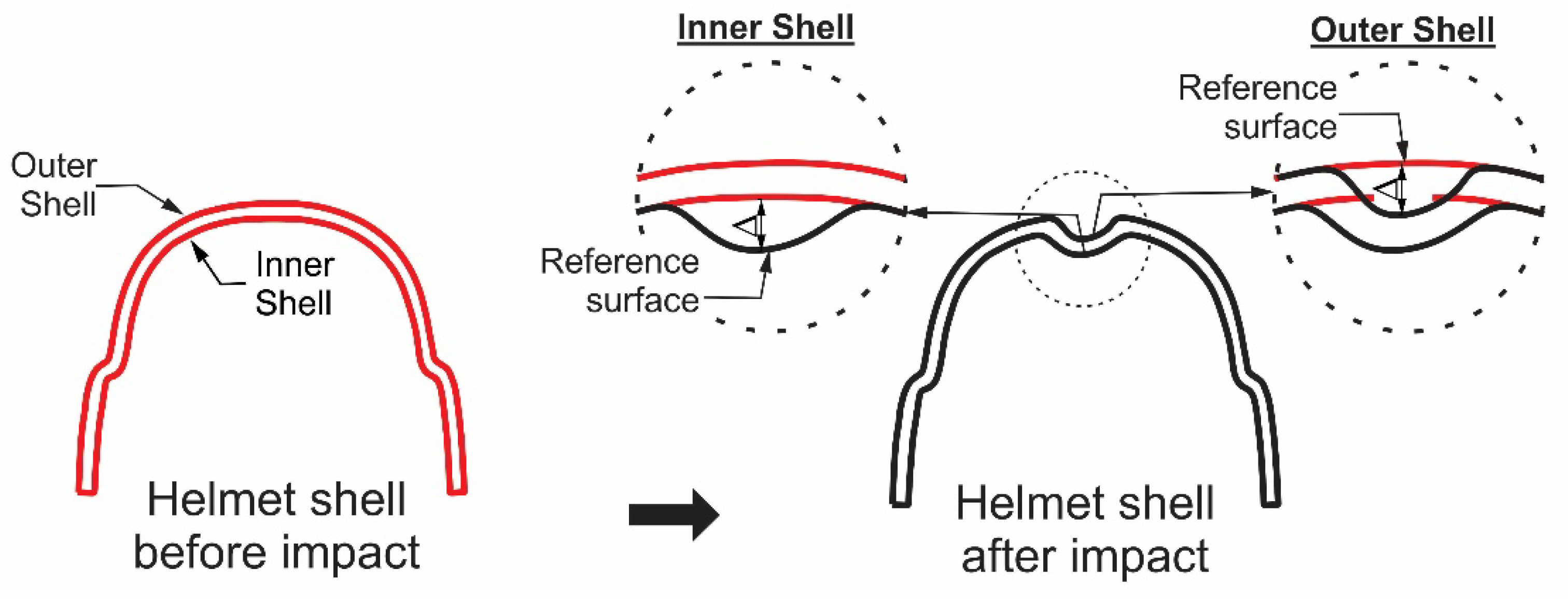
Figure 2.
(a) Seibt ES-35 single-screw extruder and (b) blown film.
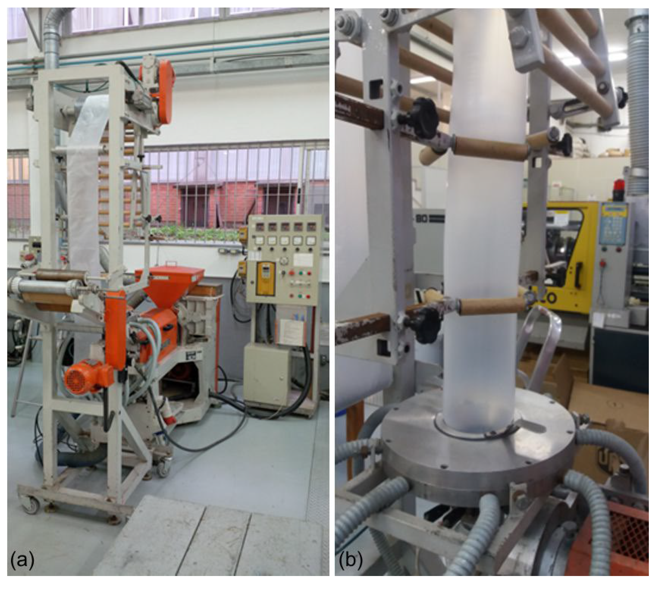
Figure 3.
Ballistic helmet manufacturing process flowchart.
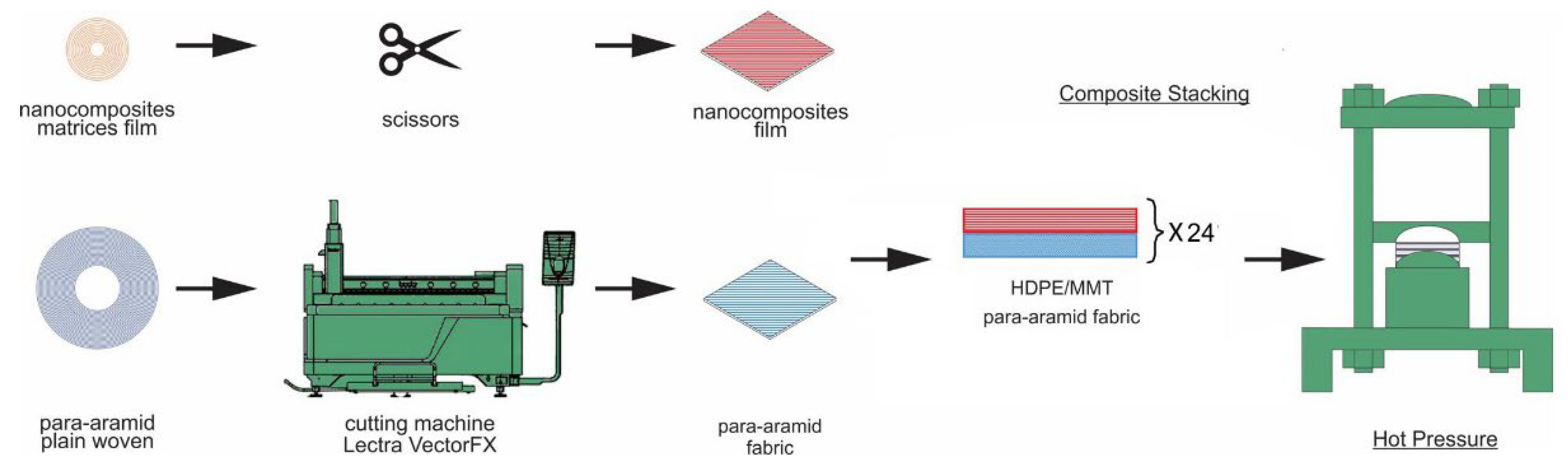
Figure 4.
Ballistic helmet pressing: (a) ACH mold; (b) layers of preform in place; and (c) pressed composite.
Figure 4.
Ballistic helmet pressing: (a) ACH mold; (b) layers of preform in place; and (c) pressed composite.
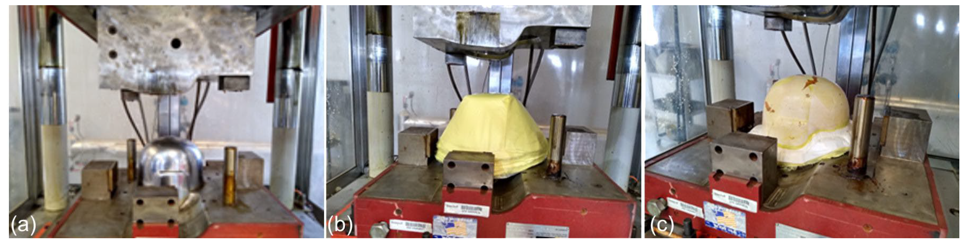
Figure 5.
Temperature‒force vs. time applied in processing.
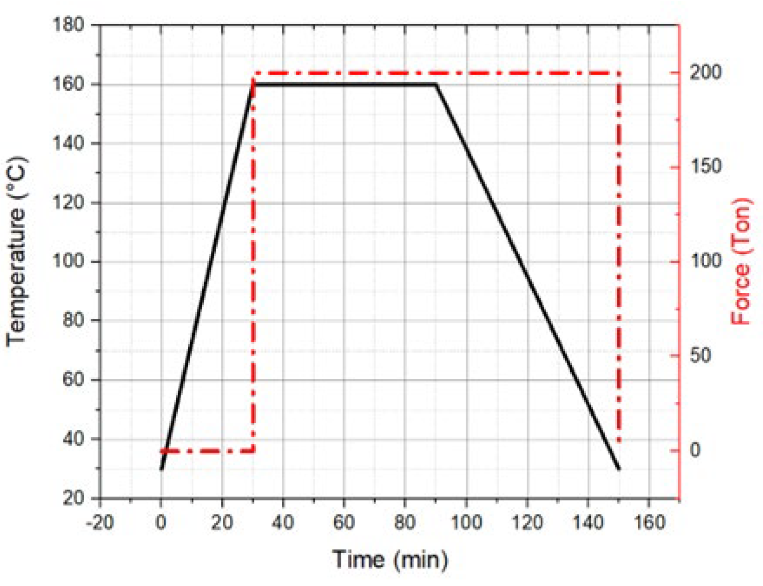
Figure 6.
Impact points (a) front, (b) right, (c) back, and (d) left.
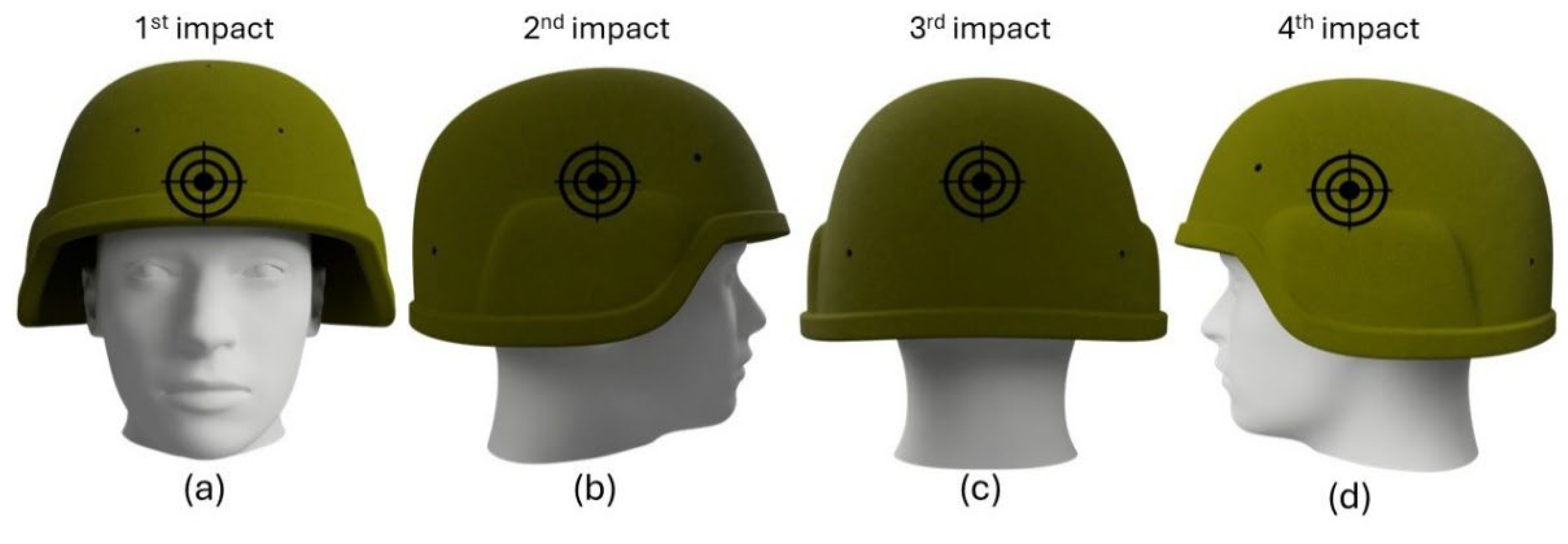
Figure 7.
Ballistic tested helmets: (a) HDPE/MMT helmet and (b) 3D reconstructed image.
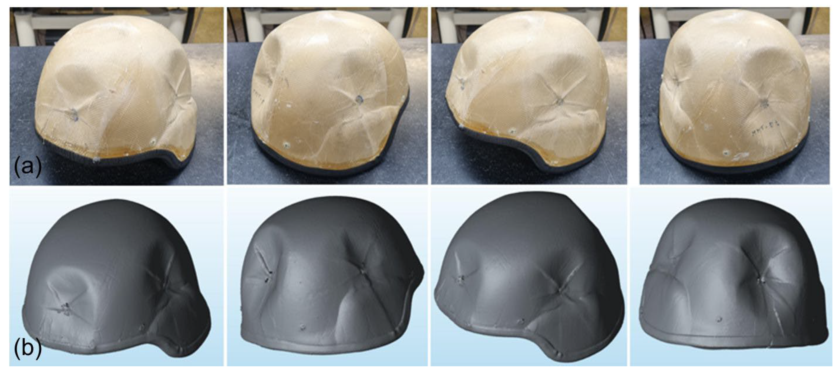
Figure 8.
Color maps of the (a) front impact outer shell, (b) front impact inner shell, (c) right im-pact outer shell, and (d) right impact inner shell.
Figure 8.
Color maps of the (a) front impact outer shell, (b) front impact inner shell, (c) right im-pact outer shell, and (d) right impact inner shell.
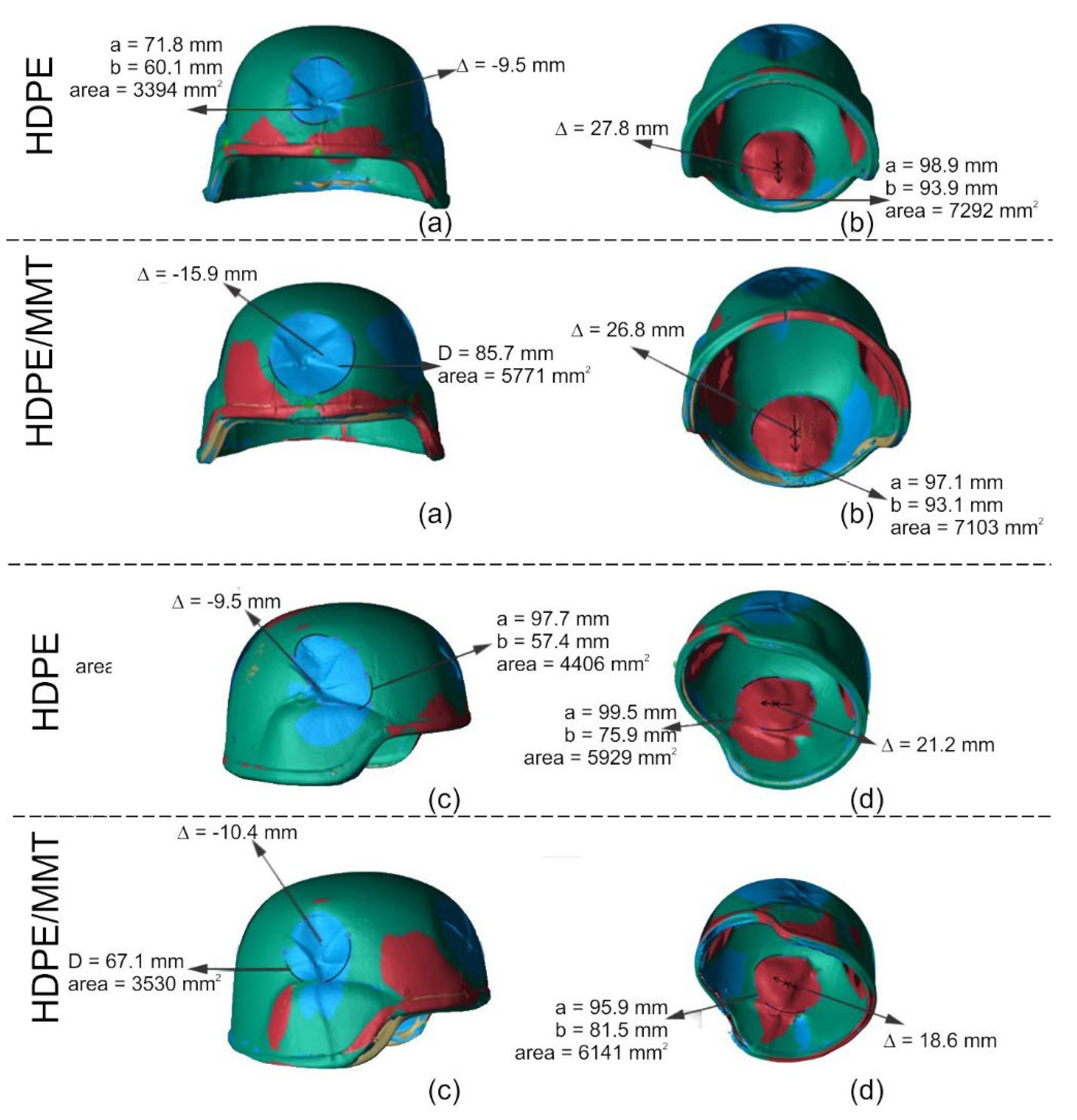
Figure 9.
Results obtained with the 3D scanning metrology method: (a) displacement and (b) area.
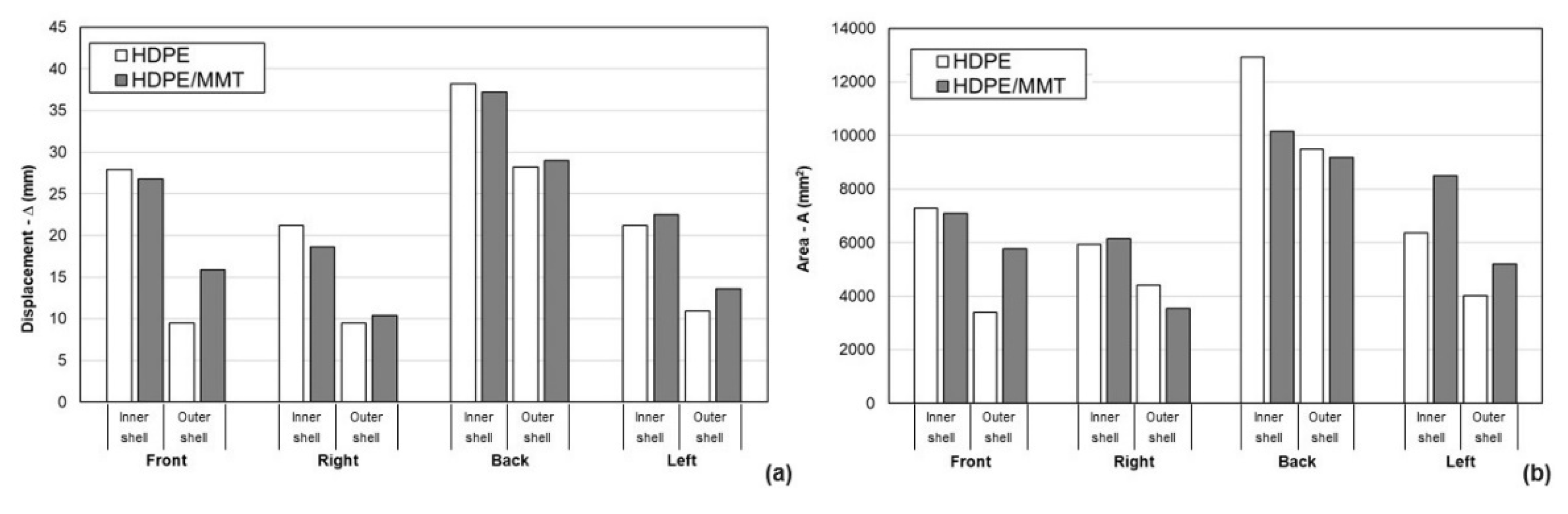
Figure 10.
X-ray tomography images of post-processed helmet shells (a) HDPE and (b) HDPE/MMT.
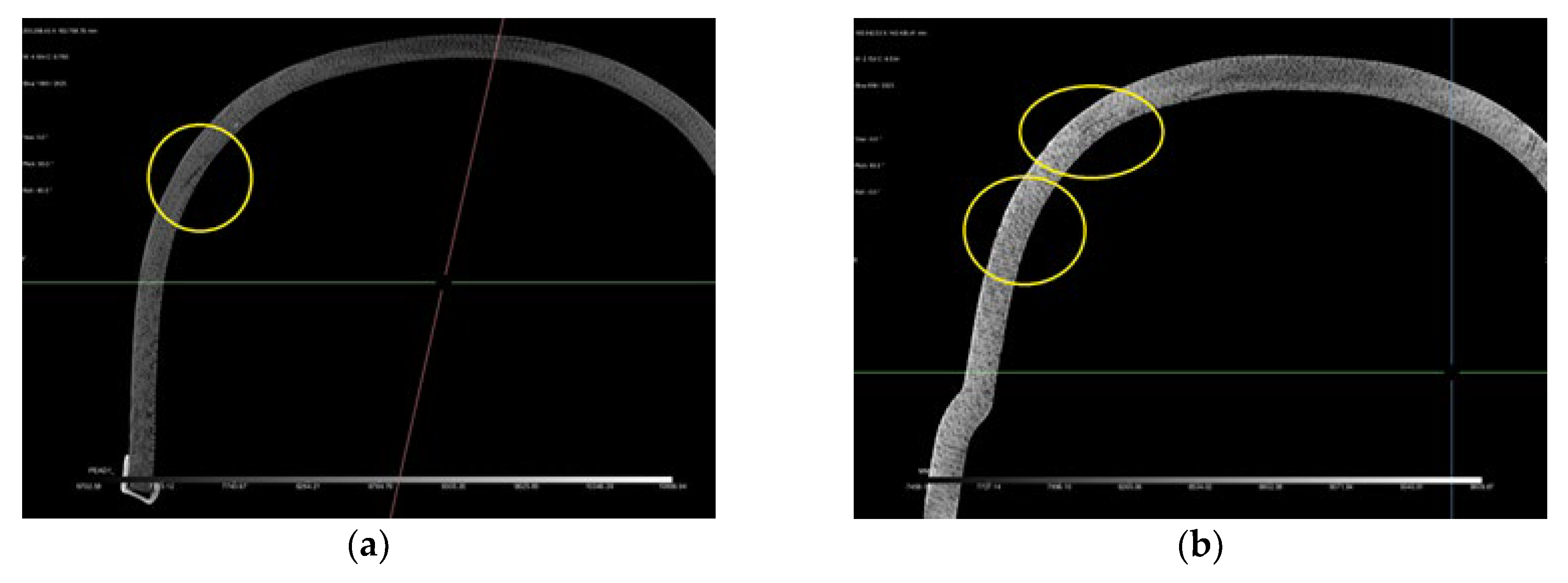
Figure 11.
X-ray CT images of the HDPE helmet after ballistic tests: (a) Global visualization of the piece; slides showing the delaminations of (b) left side impact, (c) right side impact, (d) horizontal (xy) section plane—top view showing the impact position, (e) frontal impact, and (f) back side impact.
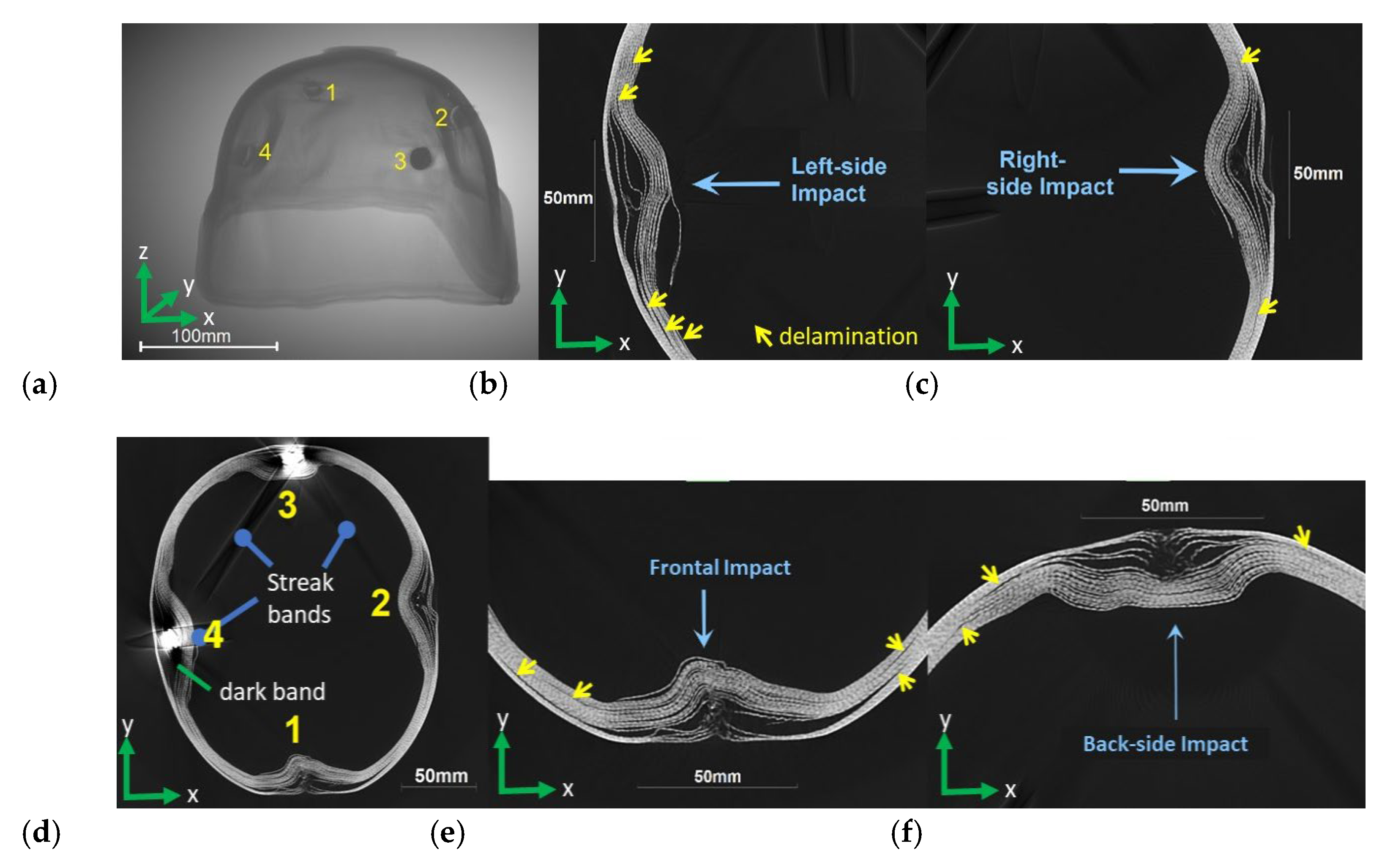
Figure 12.
X-ray CT images of the HDPE/MMT helmet after ballistic tests: (a) Global visualiza-tion of the piece; slides showing the delaminations of (b) left side impact, (c) right side impact, (d) horizontal (xy) section plane—top view showing the impact position, (e) frontal impact, and (f) back side impact.
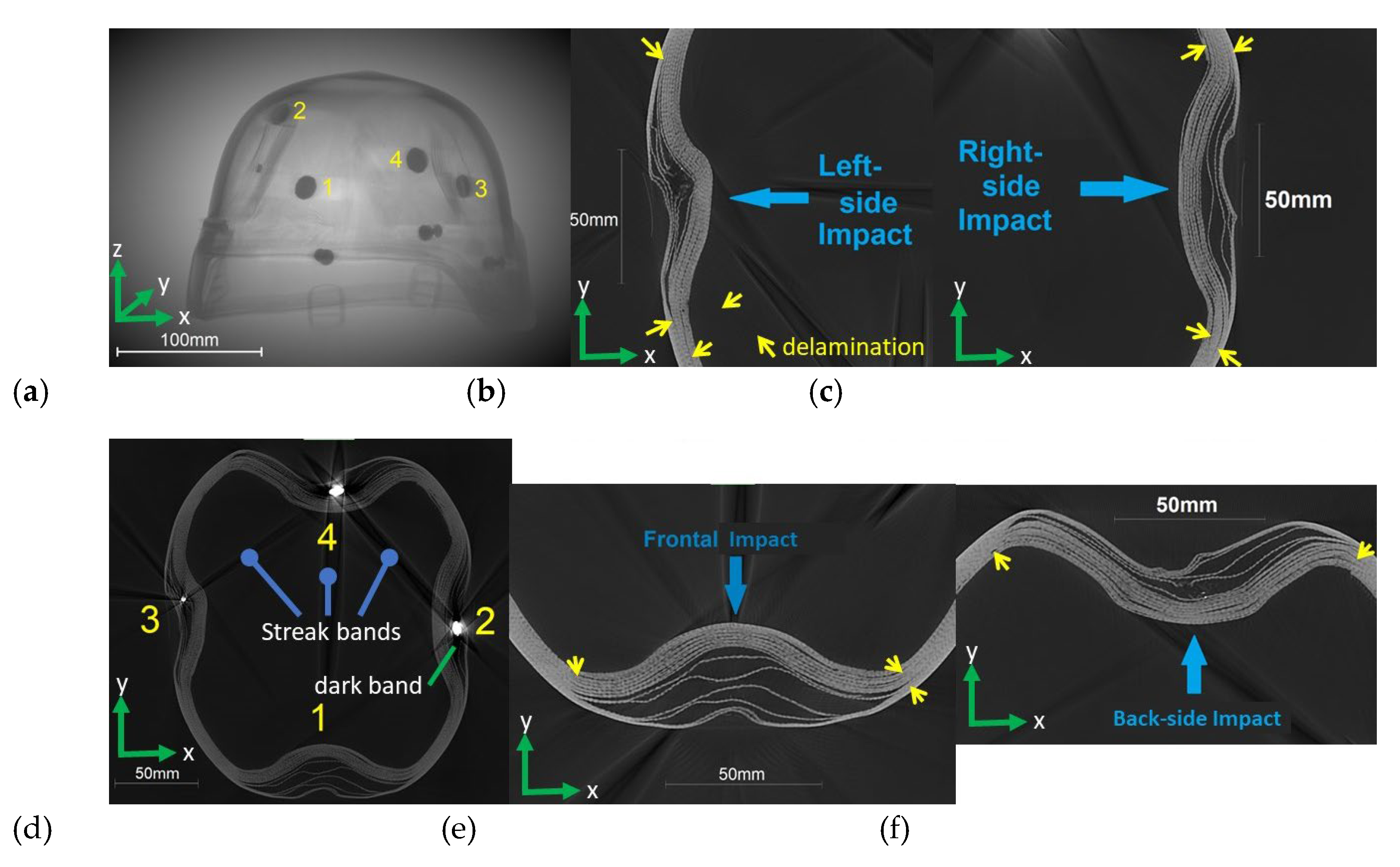

Table 1.
Ballistic test results.
| Matrix | Hit | Impact | Back Face | Classification | Speed (m/s) |
|---|---|---|---|---|---|
| HDPE | 1 | Front | Large | NP | 360.72 |
| 2 | Right | Large | NP | 364.22 | |
| 3 | Back | Large | NP | 367.67 | |
| 4 | Left | Large | NP | 360.61 | |
| HDPE/MMT | 1 | Front | Large | NP | 360.48 |
| 2 | Right | Large | NP | 362.62 | |
| 3 | Back | Large | NP | 368.24 | |
| 4 | Left | Large | NP | 364.95 |
Table 2.
Displacement and area of the scanned helmets at the impact point.
| D (mm) | |||||
| Front | Right | Back | Left | ||
| Inner shell | HDPE | 27.9 | 21.2 | 38.2 | 21.2 |
| HDPE/MMT | 26.8 | 18.6 | 37.2 | 22.5 | |
| Outer shell | HDPE | 9.5 | 9.5 | 28.2 | 10.9 |
| HDPE/MMT | 15.9 | 10.4 | 29 | 13.6 | |
| A (mm2) | |||||
| Front | Right | Back | Left | ||
| Inner shell | HDPE | 7292 | 5929 | 12919 | 6370 |
| HDPE/MMT | 7103 | 6141 | 10154 | 8502 | |
| Outer shell | HDPE | 3394 | 4406 | 9480 | 4006 |
| HDPE/MMT | 5771 | 3530 | 9187 | 5187 | |
Disclaimer/Publisher’s Note: The statements, opinions and data contained in all publications are solely those of the individual author(s) and contributor(s) and not of MDPI and/or the editor(s). MDPI and/or the editor(s) disclaim responsibility for any injury to people or property resulting from any ideas, methods, instructions or products referred to in the content. |
© 2024 by the authors. Licensee MDPI, Basel, Switzerland. This article is an open access article distributed under the terms and conditions of the Creative Commons Attribution (CC BY) license (http://creativecommons.org/licenses/by/4.0/).
Copyright: This open access article is published under a Creative Commons CC BY 4.0 license, which permit the free download, distribution, and reuse, provided that the author and preprint are cited in any reuse.


