

Submitted:
08 July 2024
Posted:
10 July 2024
You are already at the latest version
Abstract
To enhance the uplift capacity and facilitate the installation of multi-row perfobond connectors at shallow burial depths, this study puts forward a novel notched T-perfobond connector. The design incorporates an integrated flange at the bottom of the connector and a notch at the edge of the hole. Through pull-out model tests on four notched T-perfobond connectors, this research investigates their failure mechanisms and pull-out capacities. Utilizing the explicit dynamics method in Abaqus, a finite element model of the pull-out resistance test for the notched T-perfobond connector is established and verified against experimental data. Furthermore, a detailed parametric analysis involving 54 models is conducted, examining crucial parameters such as rib dimensions, hole geometry, flange size, notch width, bar diameter, and material properties. Based on the combined experimental and numerical results, the paper assesses the suitability of current formulas for calculating the pull-out capacity of perfobond connectors and proposes a refined calculation method specifically for notched T-perfobond connectors. All the findings in this paper can serve as a reference in the design and construction of composite structures.
Keywords:
composite structures
; perfobond connectors
; flange
; notch
; pull-out performance
; finite element analysis
1. Introduction
As pivotal interfacing elements in composite structures, perfobond connectors have been widely utilized in various structural systems, such as composite beams, hybrid beams, composite towers, bridge decks, and composite anchorages [1-4], due to their outstanding shear resistance, fatigue resistance, and ease of installation.
In recent years, Extensive research has been conducted on perfobond connectors, employing a variety of methodologies. Physical modeling, the first of these methodologies, involves the creation of scaled or full-sized replicas of the connectors and the structures they are a part of. In particular, push-in, push-out, and pull-out model tests are usually used to obtain the shear and tensile behavior of perfobond connectors [5-10]. This hands-on approach allows researchers to observe firsthand the mechanical interactions that occur under real-world conditions, such as the distribution of forces and the development of stresses within the composite system. Physical models are particularly useful for studying the complex interactions that cannot be fully captured by computational methods alone.
The second methodology is computational simulation, which leverages advanced software tools, such as ABAQUS and ANSYS, to create virtual models of perfobond connectors and the composite structures they are used in [11-16]. These simulations can account for a wide range of variables, including material properties, loading conditions, and environmental factors. By simulating various scenarios, researchers can predict the behavior of perfobond connectors under different circumstances, which is invaluable for optimizing their design and application.
Theoretical analysis, the third methodology, involves the development of mathematical models to describe the behavior of perfobond connectors [17-22]. This approach is based on established principles of mechanics and materials science and can provide deep insights into the fundamental mechanisms at play. Theoretical models can be used to derive equations that predict shear performance and pull-out characteristics, offering a basis for the design and evaluation of perfobond connectors.
Despite the significant amount of research, there are still notable gaps in the existing knowledge [23-25]. Firstly, while a large number of studies have focused on the shear performance of perfobond connectors, their pull-out performance has received relatively less attention. Secondly, the notches designed to facilitate the passage of steel reinforcement bars may potentially weaken the pull-out performance of the connectors, especially in the case of composite bridge decks with limited embedment depths, where the crack resistance of the concrete is a critical concern. Furthermore, although Ultra-High Performance Concrete (UHPC) has been applied in engineering to address the problem of concrete crack resistance, there is a lack of literature on the pull-out performance of perfobond connectors embedded in UHPC.
This study introduces a new notched T-perfobond connector to tackle the issues of low pull-out strength and installation challenges in multi-row perfobond connectors with shallow embedment. The connector's pull-out resistance in UHPC is deeply studied through model tests and validated with ABAQUS simulations. A parametric analysis of 54 models examines various parameters, and the study suggests an improved calculation method for the pull-out capacity of the new connectors.
2. Pull-Out Test
2.1. Test Program
As shown in Table 1, four pull-out tests were conducted on the T-perfobond connectors and notched T-perfobond connectors. The aims were to obtain the failure mode, ultimate pull-out resistance and load-separation behavior of the notched T-perfobond connectors and to verify the reliability of the finite element analysis. Depending on the type of connection, these specimens can be evenly divided into two groups: The PFR specimens with a flange of the same material at the bottom of the perfobond connector to enhance the pull-out resistance of the specimens, and the PMFR specimens with a notch at the bottom edge of the perfobond including the flange. The main parameters of the pull-out test specimens are the hole length dl, hole height dh; rib thickness tp, rib length lp; the width of the flange of the perfobond connector bf, the thickness of the flange tf, the length of the flange lf = lp; the width of the notch cw, the diameter of the rebar dr. The specimens are denoted by P for the connecting piece, R for the penetrating rebar, F for the flange, and M for the notch.
2.2. Specimen Layout
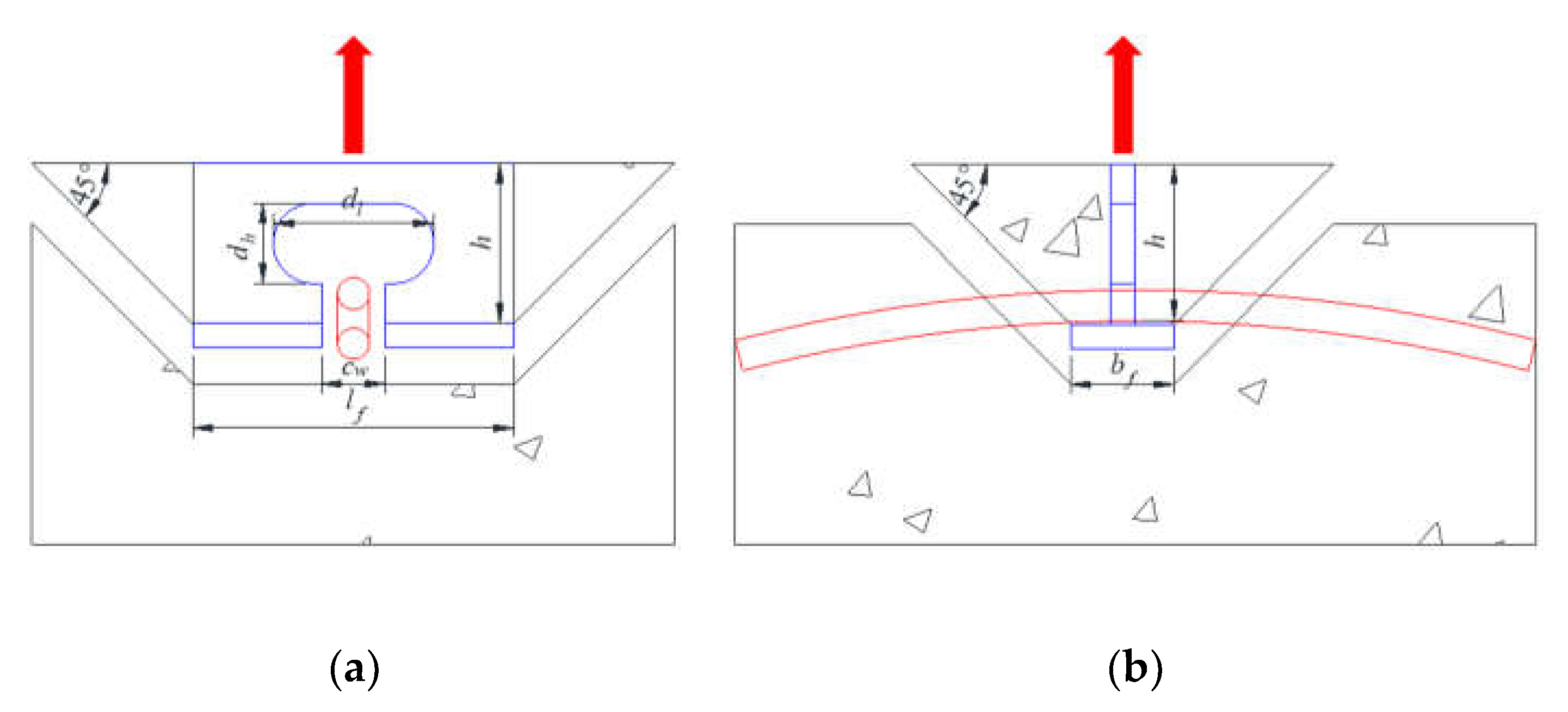
As shown in Figure 1, the constructional form of the pull-out model specimens for the perfobond connector is presented. The standard model UHPC cube has a size of 500mm×500mm×500mm. Perfobond shear connectors are vertically welded to the T-beam, and the actuator is connected to the T-beam to transfer the force to the perfobond rib. Considering that the penetrating rebar is not truncated for its full length in the actual project, it is designed to be equal to the side length of the UHPC cube, at the geometric centre of the hole. The buried depth h of the notched T-perfobond shear connectors is 40 mm. A 6 mm-thick flange is added to the bottom of the connectors to increase the thickness, with the actual buried depth being 46 mm. A 30 mm space is left between the T-beam and the concrete surface to facilitate the observation of the damage of the concrete and the perfobond rib. Four specimens are respectively embedded on all four sides of the UHPC cube. Due to the shallow buried depth of the specimens, they do not affect each other, and the design can reduce the use of UHPC materials by approximately 40%.
2.3. Details of Perfobond Ribs
Figure 2 shows the detailed structure and dimensions of the pull-out specimens of perfobond connectors. The material properties and construction dimensions of the perfobond connectors are the same except for the presence or absence of notches, and the two groups of pull-out specimens are provided with penetrating rebars. Since the embedment depth of the perfobond connectors is only 40 mm, to increase the pull-out resistance of the members, all specimen holes were long transverse hole.
2.4. Material Properties
As shown in Figure 3, steel fibers, constituting about 6.78% of the mass fraction, have been incorporated into the Ultra-High Performance Concrete (UHPC) to augment its ultimate tensile resistance. The concrete's cubic compressive strength, denoted by fcu, is measured at 118.75 MPa. Correspondingly, the uniaxial compressive strength, represented by fc, stands at 95.00 MPa, which is 80% of fcu. The tensile strength of the concrete, determined using a specimen shaped like a dog bone and labeled as ft, is recorded at 10.38 MPa. For the reinforcing bars, the yield strength (fry) and ultimate tensile strength (fru) are 351.30 MPa and 691.50 MPa, respectively. In the case of the perfobond rib and its flange, the respective yield strength (fsy) and tensile strength (fsu) are 384.67 MPa and 531.33 MPa.
2.5. Test Setup and Instrumentation
Figure 4 illustrates the loading apparatus used for the pull-out test. A vertical pull-out force was exerted on the upper section of the specimens utilizing an MTS 50t push-pull actuator. The UHPC base of each specimen was firmly anchored to the floor girder through two short steel girders, which were affixed to the floor girder by four screw connectors. A specially designed π-connector plate facilitated the linkage between the T-beam and the actuator, with the assembly being secured using high-strength tension bolts. To ascertain the separation between the perfobond rib and the concrete, two displacement transducers were symmetrically positioned on the lateral surfaces of the specimens, one on each side.
3. Test Results and Analysis
3.1. Failure Mode
The pull-out resistance of the specimens in pull-out tests is shown in Table 1. The PFR specimens are not notched at the hole edge. With the increase of vertical displacement, the constraint of concrete on the flange of the perfobond ribs is enhanced. The damage mode is that the perfobond ribs on both sides of the hole of the perfobond connector are pulled off, which results in the loss of bearing capacity of the connectors. The surface of the UHPC is intact without obvious bulges and cracks. The PMFR specimens are notched at the hole edge. Compared with the specimens without notches, the restraining area of the concrete on the flange of the perfobond connector was small. The UHPC was lifted upward diagonally along the edge of the flange at a certain angle to form a conical damage surface, which then pulled the perforated rebar out from the UHPC. The failure mode of the specimens is shown in Figure 5.
3.2. Load–Separation Behavior
Figure 6 presents the load-separation curves, illustrating the progression of separation between the steel beam and the concrete slab in response to the applied pull-out force. The curves delineate three distinct stages. Initially, upon specimen loading, the load increases linearly with separation, indicating a period of elastic behavior. As the specimens approach the damage stage, a noticeable reduction in stiffness is observed, reflecting the initiation of inelastic deformation. Post-ultimate load, the separation persists to augment while the pull-out force diminishes, signifying the onset of the post-peak softening phase.
3.3. Pull-Out Mechanism
The tensile strength of the perfobond connectors is a collective result of the perfobond rib, the flange, the concrete, and the rebar that passes through the perforations. An external force applied to the perfobond rib is transmitted from the rib, through the concrete, and into the rebar and flange. The force exerted on the perfobond rib and its immediate vicinity is the most significant and diminishes axially towards the rebar ends. The concrete dowel effect and the rebar's role are analogous to that of an elastic foundation beam. The surrounding concrete serves as a foundation, providing the reaction force for this composite elastic beam. When the perfobond rib's strength is less than that of the concrete dowel within the hole, the constraining effect of the rebar on the flange becomes critical. The fracture of the perfobond rib is the decisive factor that leads to the specimen's loss of load-bearing capacity. On the other hand, if the concrete dowel's strength predominates, an inverted pyramid-shaped wedge of concrete is formed diagonally upwards from the flange's edge. In this scenario, the concrete's punching shear failure is the determining factor that causes the ultimate loss of the specimen's load-bearing capacity, as depicted in Figure 7.
4. Numerical Simulation
4.1. General
Figure 8 displays the simulation of the pull-out test for the notched T-perfobond shear connector, conducted utilizing the finite element method. The numerical analysis aimed to elucidate the damage and pull-out resistance mechanisms inherent to these connectors. The simulation was executed using the versatile analysis software ABAQUS [26], which served as a cost-effective and time-efficient alternative to physical pull-out tests. The analysis employed a dynamic explicit method, accounting for both material and geometric nonlinearities. Given the slow loading rate of the test, the loading was treated as quasi-static.
4.2. Finite Element Type and Mesh
Figure 9 illustrates the meshing strategy for the pull-out model of the notched T-perfobond connectors, which incorporated both solid and rigid elements. The concrete slab, T-shaped steel plate, perforating rebar, and perfobond rib were represented using eight-node reduced integration hexahedral elements (C3D8R). A rigid body element (R3D4) discretized the upper surface of the T-shaped steel plate to simulate perfect bonding. To optimize analysis time, a global mesh with an average element size of 20 mm was implemented. However, for enhanced accuracy, a locally refined mesh was applied to critical areas. Specifically, the bond region of the UHPC was meshed with a minimum size of approximately 10 mm, while the perfobond ribs were further refined with a minimum mesh size of about 5 mm to capture the detailed stress distribution accurately.
4.3. Interaction and Boundary Conditions
Figure 10 depicts the setup where the reference point of the rigid body is constrained against all translational and rotational movements. An upward displacement is imposed on this reference point to simulate the pull-out action. At the interfaces between the concrete and both the perfobond connectors and the rebar, generalized contact interactions are established. To prevent interpenetration, a "hard" contact condition is specified in the normal direction. In the tangential direction, a "penalized" friction model is implemented to account for the sliding resistance. To simplify the model's actual loading boundary conditions, fixed constraints are applied to the upper surface of the concrete slab, creating a base rib. This approach effectively replicates the experimental setup within the numerical simulation.
4.4. Material Constitution of Concrete
Figure 11 illustrates the nonlinear response of concrete under compression and tension, characterized by the uniaxial compressive stress-strain curves and the relationships between tensile stress and crack width.
The intrinsic compressive behavior of concrete is articulated by Equation (1) [27]. As depicted in Figure 11a, the stress-strain curve commences with an initial linear elastic branch. Subsequently, the curve transitions into a nonlinear parabolic segment, followed by a descending branch, each reflecting different phases of the material's response under compression.
The model outlined by CEB-FIP (1993) governs the ascending segment of the curve, where σc denotes the compressive stress in MPa, and fc represents the concrete's axial compressive strength, also in MPa. The strain at the peak stress is defined as εcp=0.0035, and ξ quantifies the strain relative to the peak strain, expressed as ξ=εc/εcp. Furthermore, n is the ratio of the initial modulus of elasticity Ec to the modulus of the descending branch at the peak point Ecp, calculated as n=Ec/Ecp [27].For uncracked concrete, a linear stress-strain relationship captures the material's elongation characteristics. In contrast, the cracked section, as illustrated in Figure 11b, necessitates a nonlinear description of the stress-crack width relationship. This is articulated through Equation (2) [27].
In the provided model, σt signifies the tensile stress in MPa, while ft is the concrete's tensile strength, also expressed in MPa. The crack width is denoted by w in mm, and wc represents the crack width at complete stress relief, defined as wc=5.14GF/ft(mm), where GF is the fracture energy required to generate a unit area of stress-free crack, given by GF=0.073fc0.18(N/mm). The model incorporates constants c1=3 and c2=6.93 [27].
The concrete damage plasticity model encapsulates the degradation response of concrete under stress. This model employs two independent uniaxial damage variables, dc and dt, to quantify concrete damage resulting from compressive crushing and tensile cracking, respectively [27].
For concrete under compression, the progression of dc is linked to the plastic strain εlcp. It is determined to be proportional to the inelastic strain εcin=εc-σc/Ec, with the constant factor bc (0<bc<1) as delineated in Equation (3) [27].
In this context, dc represents the compressive damage component of concrete. The ratio of plastic to inelastic strain is denoted by bc, defined as bc=εcpl/εcin, and bc is assigned a value of 0.7 according to the study [27].
For concrete under tension, the damage evolution component d is correlated with the "plastic" crack width, wpl. This component is proportional to the actual crack width w, with the proportionality governed by the constant factor bt (where 0<bt<1 ), as described by Equation (4) [27].
Here, dt signifies the tensile damage component of the concrete. The term l0 is considered as a reference unit length for normalization purposes. Additionally, bt denotes the ratio of the 'plastic' crack width to the actual crack width, expressed as bt=wpl/w, with a designated value of 0.1 in accordance with the study cited [27].
4.5. Material Constitution of Steel
Figure 12 illustrates the stress-strain relationship for perfobond ribs and bars, modeled with three linear segments. Initially, the relationship is characterized by an elastic phase with a Young's modulus denoted as Es. This is succeeded by a yielding phase, culminating in a strain-hardening phase. It is presumed that the stress-strain behavior mirrors that of steel under compression.
4.6. Verification of Finite Element Model
The numerical simulation outcomes closely resemble the pull-out damage patterns observed in perfobond connectors, as depicted in Figure 13. In the case of notched T-perfobond connectors, an increase in pull-out force intensifies the concrete's constraint on the flange, predisposing the perfobond rib and flange to a wedge-shaped inverted pyramid damage mechanism, as illustrated in Figure 13a. Conversely, for T-perfobond connectors, the larger area of the flange in contact with the concrete during upward pull-out results in enhanced anchorage. This robust anchorage ultimately culminates in the fracture of the perfobond connectors, as shown in Figure 13b. Specifically, the peak stress in the perfobond rib reached 667.99 MPa, a threshold sufficient to confirm the rib's fracture. In the notched T-perfobond connectors, the shallow embedment depth coupled with the flange's influence means that the perforated rebar's loss of bearing capacity plays a limited role, predominantly in anchoring.
As illustrated in Figure 14, the load-separation curves derived from the finite element model (FEM) were juxtaposed with the outcomes of the pull-out tests. The experimental curves for T-perfobond connectors delineated three distinct phases: the elastic phase, the nonlinear parabolic phase, and the descending branch. With the concrete dilation angle set at 30°, the finite element analysis predicted pull-out forces of 106.51 kN for the notched T-perfobond connectors and 111.52 kN for the T-perfobond connectors. These values correspond to 106.0% and 107.5% of the average experimental results, respectively. The initial stiffness observed in the numerical simulation's load-separation curves exceeds the experimental values, possibly due to the idealized boundary conditions in the simulation, which do not account for the deformations present in the experimental setup. Additionally, discrepancies may arise from the inherent variability in the mechanical properties of the steel fiber-reinforced UHPC (Ultra-High Performance Concrete) material used in the tests.
5. Parametric Study
As shown in Table 3, a total of 54 simulations were conducted to further investigate the effects of the connectors' dimensions and material properties on the pull-out resistance of notched T-perfobond connectors. The parameters considered encompass the perfobond connector flange thickness (tf), width (bf), cut width (cw), and perfobond rib hole height (dh), hole length (dl), thickness (tp), width (lp), rebar diameter (dr), concrete axial compressive strength (fc), rebar yield strength (fry), and perfobond rib yield strength (fsy).
5.1. Influence of Flange Size
Figure 15 demonstrates the significant impact of flange thickness on the pull-out performance of notched T-perfobond connectors. An increase in flange thickness from 2 mm to 4 mm, 6 mm, 8 mm, and 10 mm resulted in corresponding pull-out resistance changes of -4.88%, 2.97%, 13.73%, and 13.90%, respectively. The findings indicate that enhancing flange thickness augments the pull-out resistance of these connectors. The primary rationale is the pronounced anchorage effect of the notched perfobond rib's bottom flange. Between 2 mm and 8 mm flange thickness, the flange is the weaker constraint, and the pull-out resistance increases linearly with flange thickness. However, when the flange thickness exceeds 8 mm, the notched perfobond rib or the concrete becomes the limiting constraint, and further increases in flange thickness yield minimal changes in pull-out resistance.
Figure 16 illustrates the substantial effect of flange width on the pull-out performance of notched T-perfobond connectors. Increasing the flange width from 6 mm, which matches the connector's thickness, to 12 mm, 18 mm, 26 mm, and 34 mm, resulted in pull-out resistance increases of 71.35%, 68.19%, 59.66%, and 49.05%, respectively. The data indicate that broadening the flange width from 6 mm to 12 mm significantly enhances the pull-out resistance due to the robust anchorage provided by the bottom flange of the connectors. However, as the flange width extends beyond 12 mm, there is a gradual decline in the ultimate pull-out resistance. This decrease may be attributed to the excessive length of the flange, which leads to a more pronounced upward force on the concrete at the junction of the notched perfobond rib and the flange. The resultant moment at the flange's outer edge, due to this force, is larger and may cause stress concentration, leading to premature concrete failure at the flange's outer edge and a consequent reduction in pull-out resistance.
5.2. Influence of Cut Width
Figure 17 displays the impact of notch width on the pull-out performance of notched T-perfobond connectors. In this study, the notched ratio cw/lf was varied from 0 to 0.50 across the specimens. The conventional T-perfobond connectors featured a notched width of 0 mm, corresponding to a notched ratio of 0. The notched T-perfobond connectors had notched widths of 8 mm, 16 mm, 24 mm, and 40 mm, with notched ratios of 0.10, 0.20, 0.30, and 0.50, respectively. The findings indicate that an increase in notch width has a minor influence on the pull-out resistance of the notched T-perfobond connectors. When the notch width is less than 16 mm, corresponding to a notch ratio below 0.20, the reduction in pull-out resistance does not exceed 4.50%. Beyond a notch width of 16 mm up to 40 mm, the ultimate pull-out resistance of the specimens remains relatively stable. This constancy could be due to the flange providing the necessary pull-out resistance to counteract the effects of the notch.
5.3. Influence of Hole Size
Figure 18 illustrates the impact of hole height on the pull-out performance of notched T-perfobond connectors. When the hole height was increased from 10 mm to 15 mm, 20 mm, 25 mm, and 30 mm, the corresponding changes in pull-out resistance were 1.59%, -1.65%, -2.87%, and -18.13%, respectively. The data reveal that while an increase in hole height from 10 mm to 15 mm slightly enhances pull-out resistance, further increases result in a decline. This trend is primarily attributed to the reduction in the perfobond rib's thickness at the lower edge of the hole as the hole height increases. Concurrently, the moment at the notch of the perfobond rib and the inner edge of the hole at its maximum length intensifies. Despite this, the projected area of the concrete dowel and the contact area of the perfobond connectors remain constant, potentially causing earlier yielding and damage at the inner edge of the hole, which in turn diminishes pull-out resistance. Examination of the load-separation curve indicates that a larger hole height correlates with an extended ductile section.
Figure 19 demonstrates the influence of hole length on the pull-out performance of notched T-perfobond connectors. As the hole length increased from 20 mm to 30 mm, 40 mm, 50 mm, and 60 mm, the pull-out resistance of these connectors changed by 3.8%, 2.43%, 2.43%, and -36.96%, respectively. The results indicate that increasing the hole length up to 50 mm slightly augments the tensile strength of the connectors; however, a further increase to 60 mm significantly reduces the pull-out resistance. This phenomenon can be primarily attributed to the reduction in the perfobond rib's thickness at the hole's edge as the hole length expands. Consequently, the moment at the notch of the perfobond rib within the hole and at the inner edge of the hole at its maximum length increases. Although the projected contact area between the concrete dowel and the perfobond connectors may increase, the earlier yielding and damage of the perfobond rib at the inner edge of the hole at its maximum length occur, leading to a decrease in pull-out resistance.
5.4. Influence of Perfobond Size
Figure 20 illustrates the significant impact of the perfobond connector's thickness on the pull-out performance of notched T-perfobond connectors. The pull-out resistance increased dramatically as the thickness of the notched perfobond rib was incremented from 2 mm to 4 mm, 6 mm, 8 mm, and 10 mm, with respective increases of 93.22%, 146.44%, 156.71%, and 147.87%. The enhancement in pull-out resistance is primarily attributed to the robust anchoring effect of the bottom flange of the perfobond rib. For thicknesses between 2 mm and 6 mm, the perfobond rib is relatively weaker compared to other structural elements, and thus, the pull-out resistance increases linearly with the thickness of the perfobond rib. Once the thickness exceeds 6 mm, the perfobond rib's strength surpasses the constraints imposed by the concrete and rebars in the holes. Consequently, further increases in the perfobond rib's thickness lead to a continued rise in pull-out resistance. However, beyond a certain point, additional thickness does not yield a significant change in pull-out resistance.
Figure 21 demonstrates the significant impact of the notched perfobond rib's length on the pull-out performance of notched T-perfobond connectors. As the perfobond rib's length increased from 60 mm to 70 mm, 80 mm, 90 mm, and 100 mm, the pull-out resistance of the notched T-perfobond connectors correspondingly rose by 45.2%, 68.8%, 85.83%, and 83.11%. The enhancement in pull-out resistance is primarily due to the substantial anchoring effect of the bottom flange of the perfobond rib. Between lengths of 60 mm and 90 mm, the perfobond rib is relatively weaker compared to other structural constraints, and the ultimate resistance of the connectors increases linearly with the length of the perfobond rib. When the length exceeds 90 mm, the strength of the perfobond rib surpasses the constraints imposed by the concrete and rebars in the holes, suggesting that further increases in rib length may not significantly enhance pull-out resistance.
5.5. Influence of Rebar Diameter
Figure 22 illustrates the impact of rebar diameter on the pull-out performance of notched T-perfobond connectors. Increments in rebar diameter from 4 mm to 6 mm, 8 mm, 10 mm, and 12 mm resulted in minimal changes in pull-out resistance: -0.12%, -3.08%, -1.46%, and -0.34%, respectively. The findings indicate that the rebar diameter exerts negligible influence on the ultimate pull-out resistance of the specimens. This outcome is likely attributed to the dominant anchorage effect provided by the flange and the notches, which overshadows the impact of rebar diameter variations on the ultimate resistance to pull-out.
5.6. Influence of Material Strength
Figure 23 demonstrates the influence of concrete strength on the pull-out performance of notched T-perfobond connectors. As concrete strength escalated from 80 MPa to 95 MPa, 110 MPa, 130 MPa, and 140 MPa, the corresponding increases in pull-out strength were 8.87%, 22.79%, 25.31%, and 25.29%, respectively. The data indicate that the pull-out resistance of these connectors increases significantly with rising concrete strength, likely due to the strong anchorage effect of the flange. The predominant mode of specimen damage is concrete punching, and the pull-out resistance correlates linearly with concrete strength. Utilizing high-strength concrete can, therefore, enhance the pull-out resistance of notched T-perfobond connectors. However, beyond a concrete strength of 110 MPa, there is a tendency for the pull-out resistance to plateau. This saturation may occur because, at certain strength levels, the concrete's anchoring effect on the flange surpasses the strength of the notched perfobond rib, making the rib itself the limiting factor.
Figure 24 illustrates the impact of rebar strength on the pull-out performance of notched T-perfobond shear connectors. Notably, the pull-out resistance remained essentially constant as rebar strength increased from 235 MPa to 335 MPa, 400 MPa, and 500 MPa. The findings indicate that variations in rebar strength have a negligible effect on the pull-out resistance of the specimens. This outcome is likely due to the overwhelming anchorage effect of the flange and the notches, which diminishes the influence of rebar strength changes on pull-out resistance.
Figure 25 demonstrates the impact of the perfobond rib's strength on the pull-out performance of notched T-perfobond connectors. As the strength of the perfobond rib increased from 235 MPa to 345 MPa, 390 MPa, 420 MPa, and 460 MPa, the pull-out strength correspondingly rose by 41.65%, 41.82%, 41.29%, and 52.61%, respectively. The results indicate that the pull-out resistance of the notched T-perfobond connectors increases significantly with the strength of the notched perfobond ribs. This substantial increase may be attributed to the linear relationship between pull-out resistance and the strength of the perfobond rib, facilitated by the exceptionally strong anchorage provided by the bottom flange of the notched perfobond rib, which is relatively weaker compared to other restraining elements.
6. Analytical Work
The damage modes are categorized into two types: perfobond rib fracture and concrete punching. For each specimen, the ultimate pull-out resistance, denoted as Tu, is defined as the minimum value between the calculated resistances for perfobond rib fracture, Ts, and concrete punching, Tc.
6.1. Fracture Damage of Perfobond Ribs
When the strength of the perfobond rib is lower than the anchoring effect provided by the concrete and the perforating rebar on the flange, the perfobond rib typically experiences stress concentration at the hole's maximum length first. This concentration of stress initiates at the point where the rib is most likely to fracture. The fracture damage of the perfobond rib can be assessed using the calculation detailed in Equation (6).
where fs represents the tensile strength of the perforated steel plate, a measure of its capacity to withstand pulling forces before breaking. Meanwhile, As denotes the cross-sectional area at the point where the perforated steel plate fractures, which is considered to be the largest area involved in the breakage.
6.2. Punching Damage of Concrete
As depicted in Figure 26, the model resembles a wedge-shaped inverted pyramid with diagonal edges each making a 45° angle with the horizontal plane. Owing to the exceptionally strong anchorage provided by the flange, once the concrete is lifted and damaged, the concrete dowel and the rebar within the hole no longer contribute to the ultimate tensile resistance. Consequently, Equation (7) considers the concrete damage as the determining factor, based on the specimens' damage patterns, and Equation (8) accounts for the reduction in the flange area of the notched specimens on the pull-out resistance, with the discounting factor being a piecewise function.
 where, Tc signifies the pull-out resistance corresponding to the concrete damage mode. The tensile strength of the concrete, represented by ft, is considered to be one-tenth of the concrete's compressive strength, fc. Furthermore, Sh denotes the projected area of the concrete subjected to punching damage. The discount factor for the notch width, β, is defined as β=1−cw/lf≥0.8, with the constraint that 0≤cw/lf≤0.2.
Figure 26.
Punching damage of concrete. (a) Side view; (b) front view.
6.3. Comparison and Validation
Figure 27 presents a comparison of the calculated pull-out resistance with the results from pull-out tests and parametric analyses to validate the previously proposed equation. As illustrated in Figure 27a, the Equation (7) tends to overestimate the pull-out resistance of notched T-perfobond connectors. This discrepancy may stem from the omission of the effect caused by discounting the notched area in Equation (7). The pull-out resistance calculated using the modified Equation (8) aligns more closely with both the test and numerical simulation outcomes, as shown in Figure 27b. Therefore, Equations (5), a combination of Equations (6) and (8) , is deemed suitable for assessing the pull-out resistance of notched T-perfobond connectors in steel-concrete composite structures.
7. Conclusions
Based on the pull-out tests, numerical analyses, parametric studies, and analytical work on notched T-perfobond connectors, the following conclusions are drawn:
- (1)
- The pull-out damage modes for notched T-perfobond connectors consist of perfobond rib fracture and concrete punching damage. As the pull-out force increases, the interaction between the perforating rebar and the notched T-perfobond rib diminishes, making the connectors more susceptible to concrete damage in a wedge-shaped inverted pyramid pattern. In contrast, for un-notched T-perfobond connectors, the strong interaction between the perforating rebar and the perfobond rib, along with the anchorage effect of the concrete, leads to the fracture of the perfobond connectors. Notably, these damage modes do not exhibit the extensive fine cracks on the concrete surface that are typical of conventional concrete.
- (2)
- The finite element method proposed is validated through comparison with pull-out test results, showing a high degree of similarity with the observed pull-out damage. The analytical pull-out resistance values are 106.0% and 84.5% of the average test results for notched and un-notched T-perfobond connectors, respectively. This indicates that the finite element model can reliably generate parametric results for the pull-out performance of these connectors.
- (3)
- A total of 54 parameter simulations indicate that increasing the dimensions of the flange and perfobond rib, as well as the strength of the concrete and perfobond rib, can significantly enhance the pull-out resistance of notched T-perfobond shear connectors. However, excessively large perfobond dimensions can reduce this resistance, and the perforating rebar has limited effect on pull-out resistance. When the notched ratio cw/lf is less than 0.2, the pull-out resistance is slightly reduced, but it does not decrease further when the ratio exceeds 0.2, due to the strong anchoring effect of the flange.
- (4)
- An analytical model has been proposed to estimate the pull-out resistance of notched T-perfobond connectors. This model's formula for calculating pull-out resistance correlates well with test and numerical simulation results, demonstrating its utility for evaluating the pull-out resistance of these connectors.
Author Contributions
Zifa Dong conducted finite element simulation and wrote articles, Shuangjie Zheng applied for projects and made overall plans, Lizhe Jiao completed model experiments, Xiaoqing Xu participated in formulating the experimental plan, Yao Yao and Zhuoru Gao participated in experiments and simulations, Haifeng Li participated in formulating project planning schemes.
Funding
The research described in this paper was financially supported by Grants from Natural Science Foundation of China (51808235), Fujian Provincial Natural Science Foundation of China (2018J05083), Promotion Program for Young and Middle-aged Teacher in Science and Technology Research of Huaqiao University (ZQN-813), Huaqiao University Scientific Research Funding (16BS804), and College Students' Innovation and Entrepreneurship Training Program Project (S202310385013).
Conflicts of Interest
The authors declare no conflicts of interest.
Nomenclature
| dl | hole length | dh | hole height | |
| dr | diameter of the rebar | tp | perfobond rib thickness | |
| tf | flange thickness | bf | flange breadth | |
| lf | flange length | lp | perfobond rib length | |
| cw | cut width | h | perfobond rib burial depth | |
| Tu | pull-out resistance | Tu,avg | averaged pull-out resistance | |
| fcu | concrete cube strength | fc | uniaxial compressive strength | |
| fry | yield strength of the reinforcing bar | fru | tensile strength of the reinforcing bar | |
| fsy | yield strength of the perfobond rib | fsu | tensile strength of the perfobond rib | |
| σc | compressive stress of concrete | εc | compressive strain of concrete | |
| εcp | peak strain of concrete | ξ | ratio of strain to peak strain | |
| Ec | Young’s modulus of concrete | Ecp | peak point cut line modulus | |
| n | ratio of peak point cut line modulus to initial modulus of elasticity | σt | tensile stress of concrete | |
| ft | tensile strength of concrete | w | crack width of concrete | |
| wc | crack width at the complete release of stress | GF | fracture energy required to create a unit area of stress-free crack | |
| ci | constants (i = 1,2) | dc | uniaxial damage variables of concrete due to compressive crushing | |
| dt | uniaxial damage variables of concrete due to tensile cracking | εcpl | plastic strain of concrete | |
| εcin | inelastic strain of concrete | bc | constant factor for concrete damage in compression | |
| wpl | “plastic” crack width of concrete | bt | constant factor for concrete damage in tension | |
| l0 | unit length | Es | Young’s modulus of steel | |
| Tu | pulling resistance | Tc | tensile bearing capacity calculated from concrete strengths | |
| Ts | tensile resistance calculated from the strength of the perfobond connectors | As | fractured cross-sectional area of perfobond connectors | |
| Sh | projected area of concrete punching damage surface | β | influence factor of the notch |
References
- He S, Yang G, Jiang Z, et al. Effective width evaluation for HSS-UHPC composite beams with perfobond strip connectors [J]. Engineering Structures, 2023, 295: 116828. [CrossRef]
- Ma Y, Zhang B, Peng A, et al. Experimental and analytical investigation on shear mechanism of steel-UHPC composite T-perfobond connectors [J]. Engineering Structures, 2023, 286: 116061. [CrossRef]
- Sun L, Liu Y, Wang H, et al. Tensile stiffness of perfobond rib connectors in steel–concrete composite pylon of bridges [J]. Engineering Structures, 2023, 284: 115931. [CrossRef]
- Zhan Y, Huang W, Li Y, et al. Experimental investigation on mechanical behavior of T-type perfobond rib shear connectors under combined shear and tension [J]. Journal of Building Engineering, 2023, 73: 106840. [CrossRef]
- Cândido-Martins J P S, Costa-Neves L F, Vellasco P C G S. Experimental evaluation of the structural response of perfobond connectors [J]. Engineering Structures, 2010, 32(8): 1976-1985. [CrossRef]
- Vianna J C, De Andrade S A L, Vellasco P C G S, et al. Experimental study of perfobond connectors in composite construction [J]. Journal of Constructional Steel Research, 2013, 81: 62-75. [CrossRef]
- Kim Y H, Kang J Y, Koo H B, et al. Pull-Out Resistance Capacity of a New perfobond connector for Steel Pile Cap Strengthening [J]. Advances in Materials Science and Engineering, 2016(1): 1374689. [CrossRef]
- He S, Fang Z, Mosallam A S. Push-out tests for perfobond strip connectors with UHPC grout in the joints of steel-concrete hybrid bridge girders [J]. Engineering Structures, 2017, 135: 177-190. [CrossRef]
- Di J, Zou Y, Zhou X, et al. Push-out test of large perfobond connectors in steel–concrete joints of hybrid bridges [J]. Journal of Constructional Steel Research, 2018, 150: 415-429. [CrossRef]
- Zheng S, Liu Y, Liu Y, et al. Experimental and parametric study on the pull-out resistance of a notched perfobond connector [J]. Applied Sciences, 2019, 9(4): 764. [CrossRef]
- Oguejiofor E C, Hosain M U. Numerical analysis of push-out specimens with perfobond rib connectors [J]. Computers & Structures, 1997, 62(4): 617-624. [CrossRef]
- Al-Darzi S Y K, Chen A R, Liu Y Q. Finite element simulation and parametric studies of perfobond rib connector [J]. American Journal of Applied Sciences, 2007, 4(3): 122-127. [CrossRef]
- Zheng S, Liu Y, Yoda T, et al. Parametric study on shear capacity of circular-hole and long-hole perfobond connector [J]. Journal of Constructional Steel Research, 2016, 117: 64-80. [CrossRef]
- Kim K S, Han O, Gombosuren M, et al. Numerical simulation of Y-type perfobond rib shear connectors using finite element analysis [J]. Steel and Composite Structures, 2019, 31(1): 53-67. [CrossRef]
- Karam M S, Yamamoto Y, Nakamura H, et al. Numerical evaluation of the perfobond (PBL) shear connector subjected to lateral pressure using coupled rigid body spring model (RBSM) and nonlinear solid finite element method (FEM) [J]. Crystals, 2020, 10(9): 743. [CrossRef]
- Suzuki A, Suzuki K, Kimura Y. Ultimate shear strength of perfobond connectors subjected to fully reversed cyclic loading [J]. Engineering Structures, 2021, 248: 113240. [CrossRef]
- Vianna J C, Costa-Neves L F, Vellasco P C G S, et al. Experimental assessment of Perfobond and T-perfobond connectors’ structural response[J]. Journal of Constructional Steel Research, 2009, 65(2): 408-421. [CrossRef]
- Munemoto S, Sonoda Y. An analytical study on dynamic strength evaluation of perfobond strip shear connectors[J]. Applied Mechanics and Materials, 2014, 566: 179-184. [CrossRef]
- Zheng S, Liu Y, Yoda T, et al. Shear behavior and analytical model of perfobond connectors[J]. Steel and Composite Structures, 2016, 20(1): 71-89. [CrossRef]
- Zheng S, Zhao C, Liu Y. Analytical model for load–slip relationship of perfobond connector based on push-out test [J]. Materials, 2018, 12(1): 29. [CrossRef]
- Zhu Y Y, Nie X, Fan J S, et al. Experimental and analytical investigation on pull-out performance of multihole thin-rib perfobond connectors [J]. Journal of Bridge Engineering, 2019, 24(5): 04019037. [CrossRef]
- He S, Guan P, Wang Q, et al. Investigation on structural performance of perfobond strip connector group in steel-concrete joints [J]. Engineering Structures, 2021, 242: 112571. [CrossRef]
- Zhao Q, Zhang G, Liao S, et al. Static behavior of small-rib-height perfobond connectors embedded in UHPC: Experimental and analytical studies [J]. Journal of Building Engineering, 2024, 85: 108750. [CrossRef]
- Liu Y, Yang H, Luan L, et al. Three failure modes of high-strength steel (HSS) perfobond connector embedded in UHPC [J]. Engineering Structures, 2023, 286: 116147. [CrossRef]
- He S, Li Q, Yang G, et al. Experimental study on flexural performance of HSS-UHPC composite beams with perfobond strip connectors [J]. Journal of Structural Engineering, 2022, 148(6): 04022064. [CrossRef]
- ABAQUS Documentation, Version 6.10; Dassault System: Waltham, WA, USA, 2010.
- Hordijk, D.A. Tensile and tensile fatigue behaviour of concrete; experiments, modelling and analyses. Heron, 1992, 37, 1.
Figure 1.
Layout of pull-out test specimens. (a) Front view; (b) side view; (c) top view; (d) 3D view.
Figure 1.
Layout of pull-out test specimens. (a) Front view; (b) side view; (c) top view; (d) 3D view.
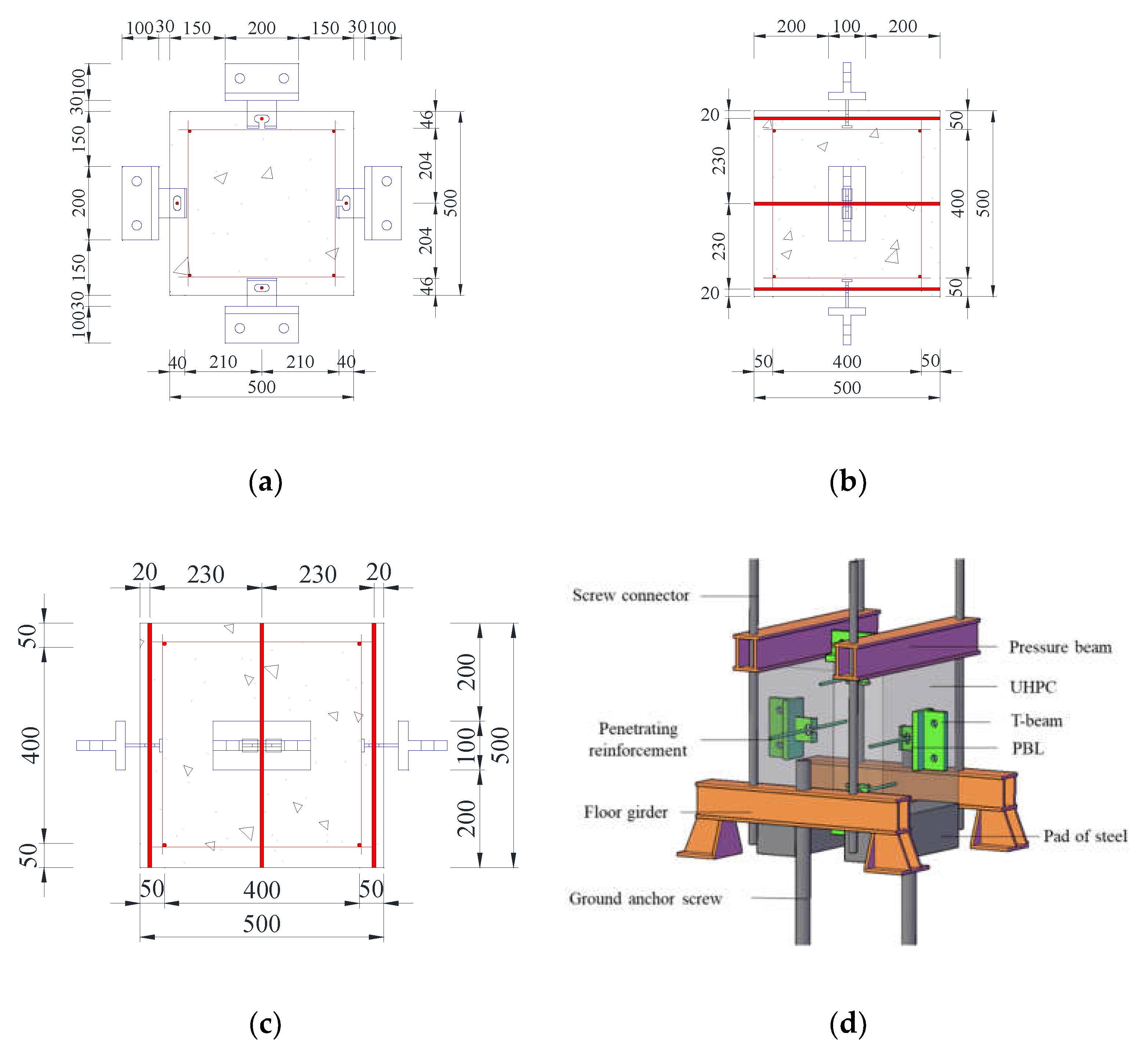
Figure 2.
Details of perfobond ribs. (a) T-perfobond rib; (b) notched T-perfobond rib.
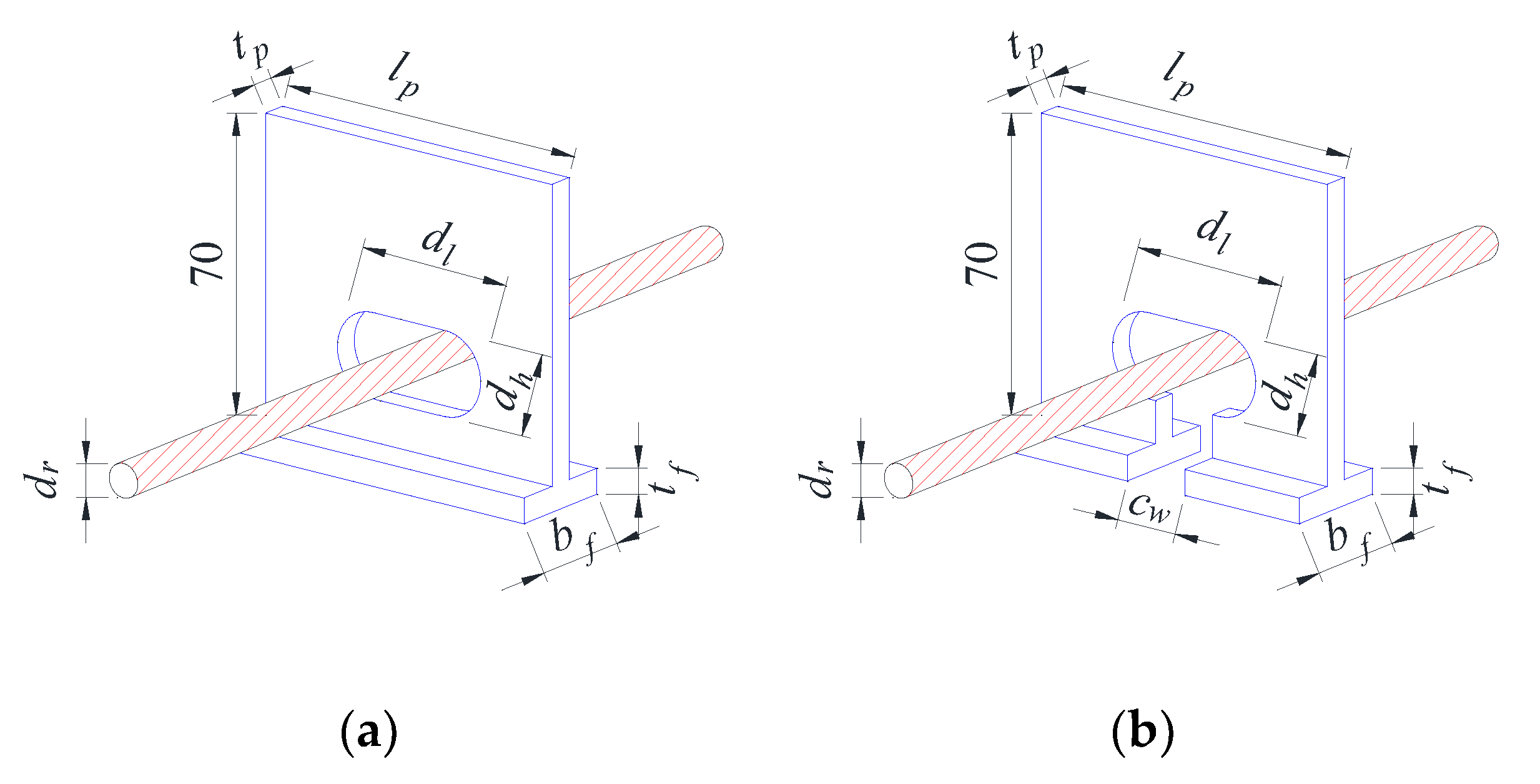
Figure 3.
Steel fibers.
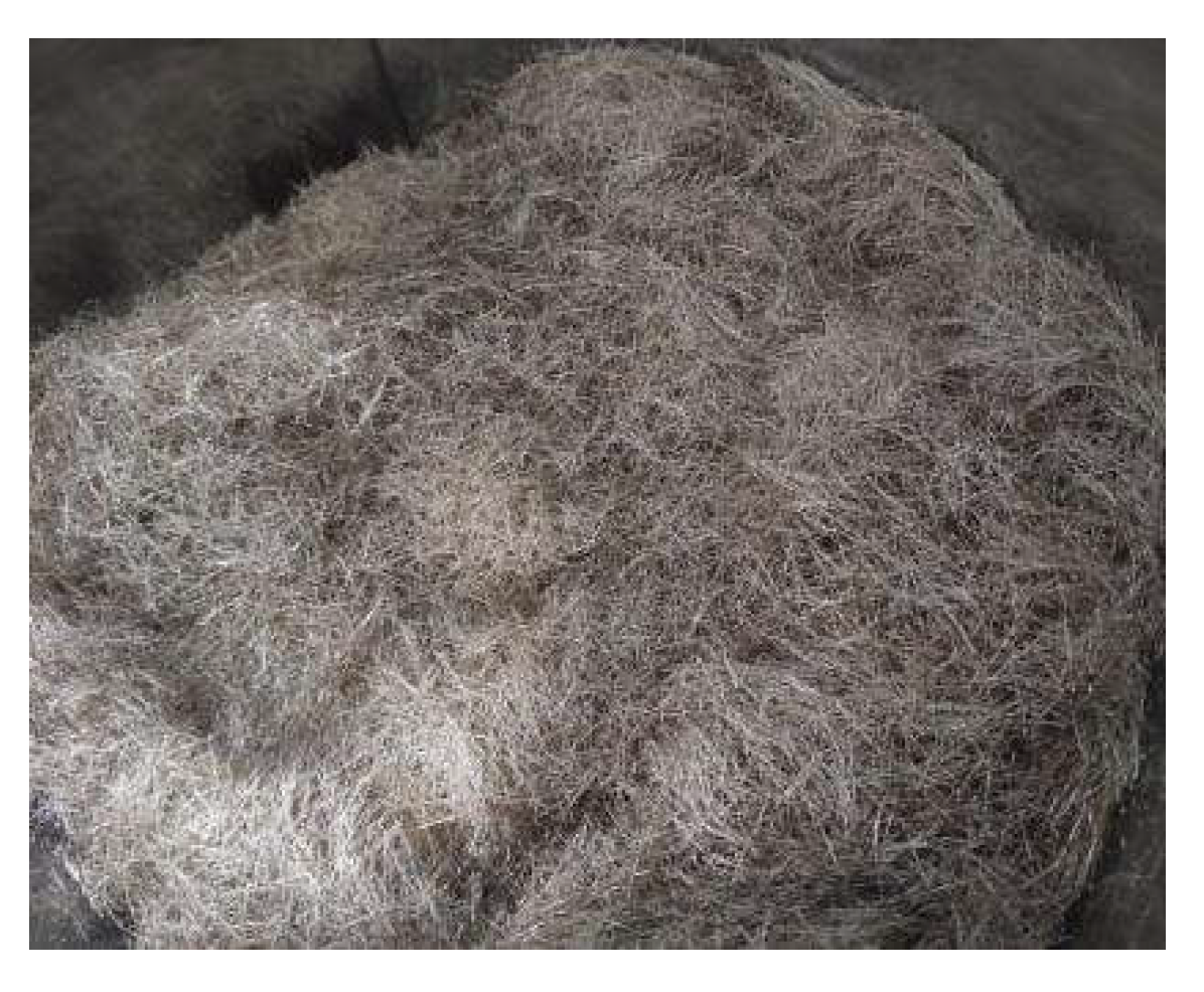
Figure 4.
Test setup and instrumentation.
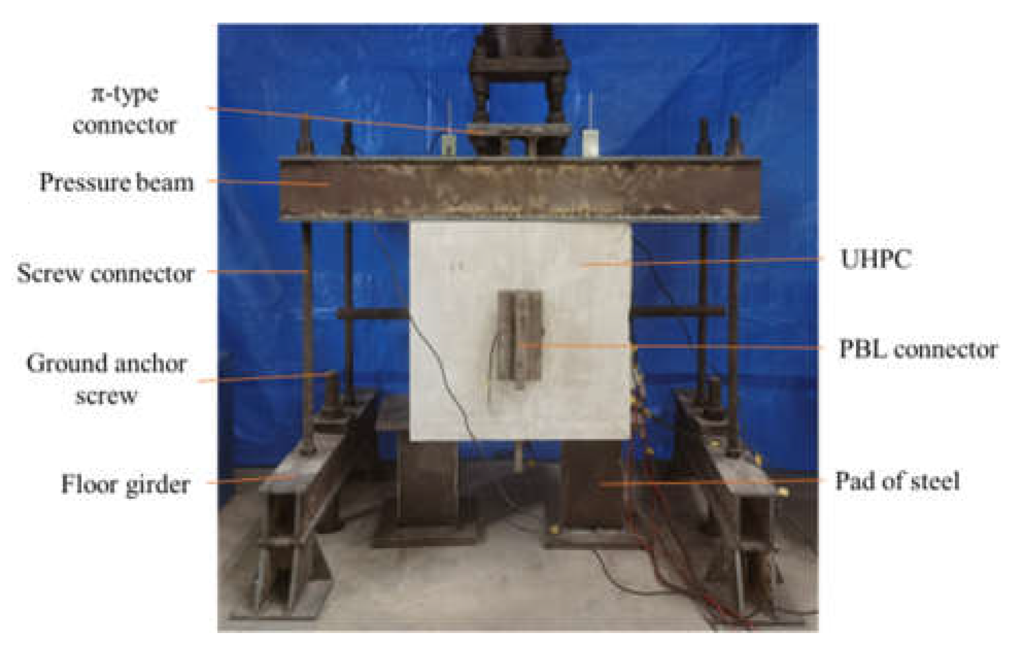
Figure 5.
Uplift failures of spicemens. (a) Fracture damage of perfobond ribs of PFR; (b) concrete punching damage of PMFR.
Figure 5.
Uplift failures of spicemens. (a) Fracture damage of perfobond ribs of PFR; (b) concrete punching damage of PMFR.
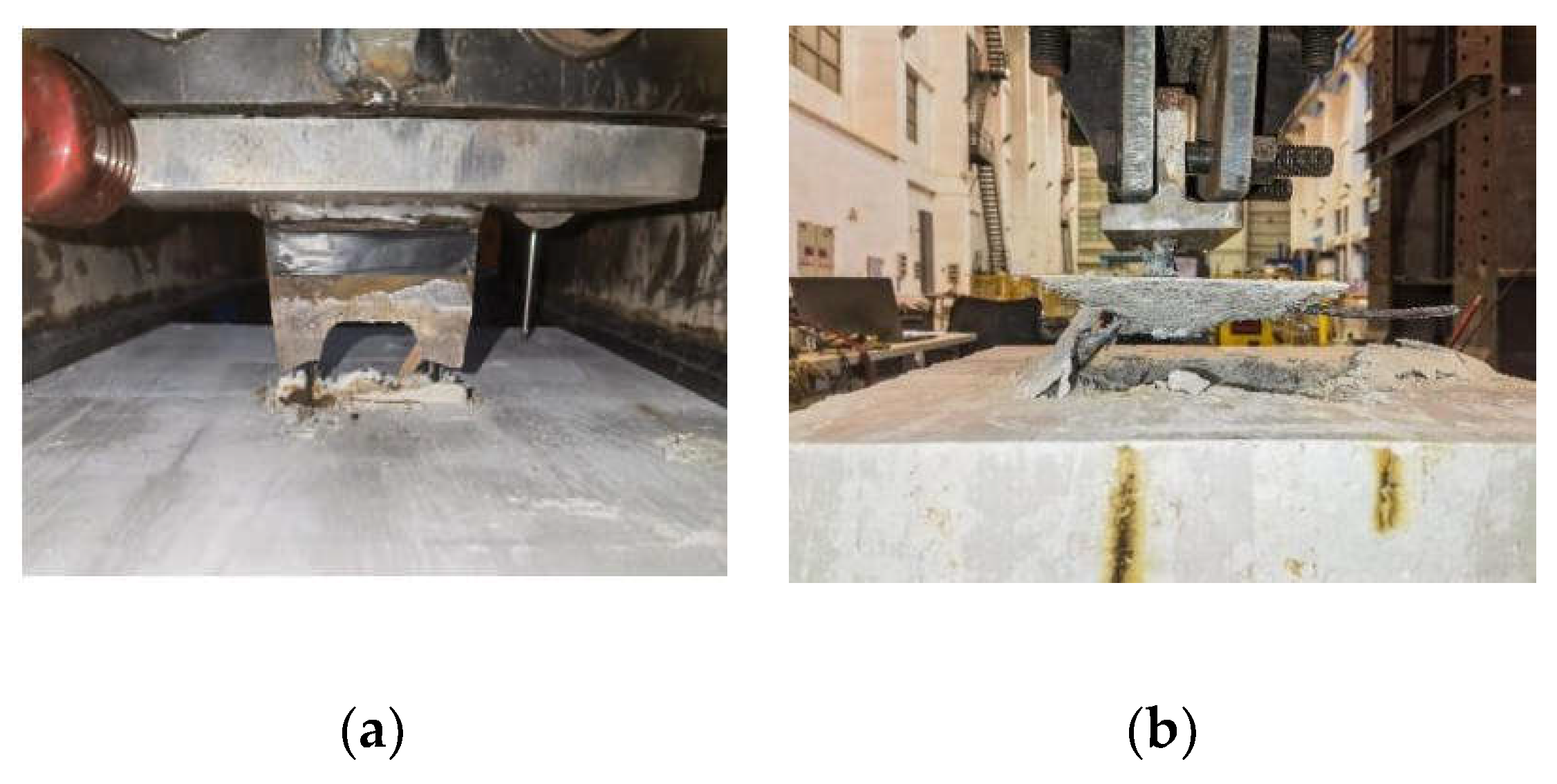
Figure 6.
Load–separation curves. (a) PFR; (b) PMFR.
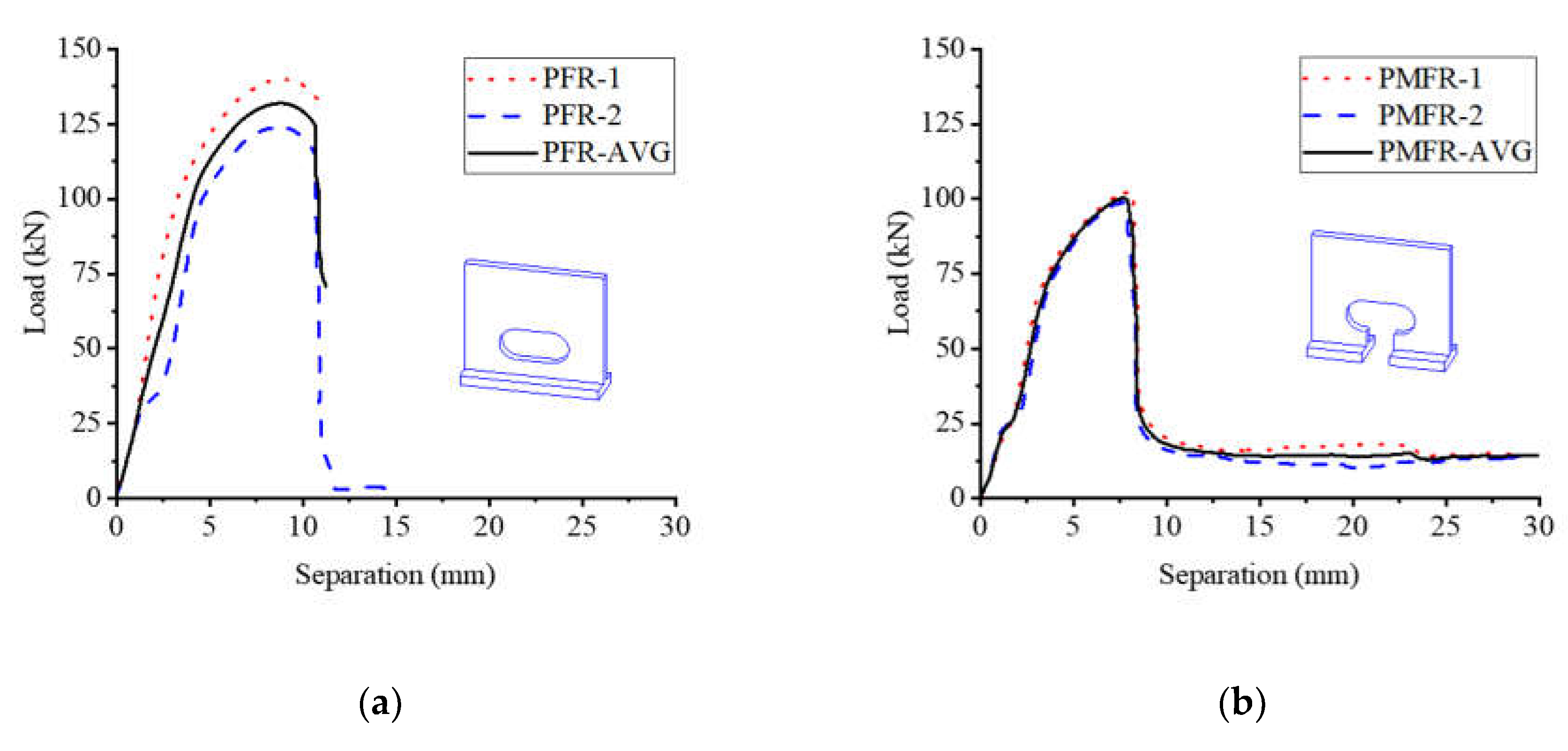
Figure 7.
Pull-out mechanism. (a) T-perfobond; (b) notched T-perfobond.
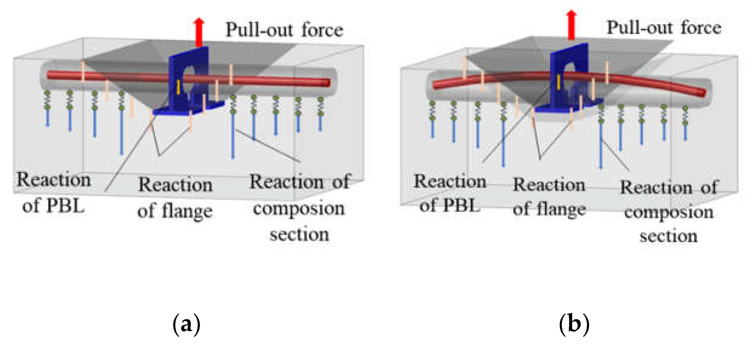
Figure 8.
Finite element model.
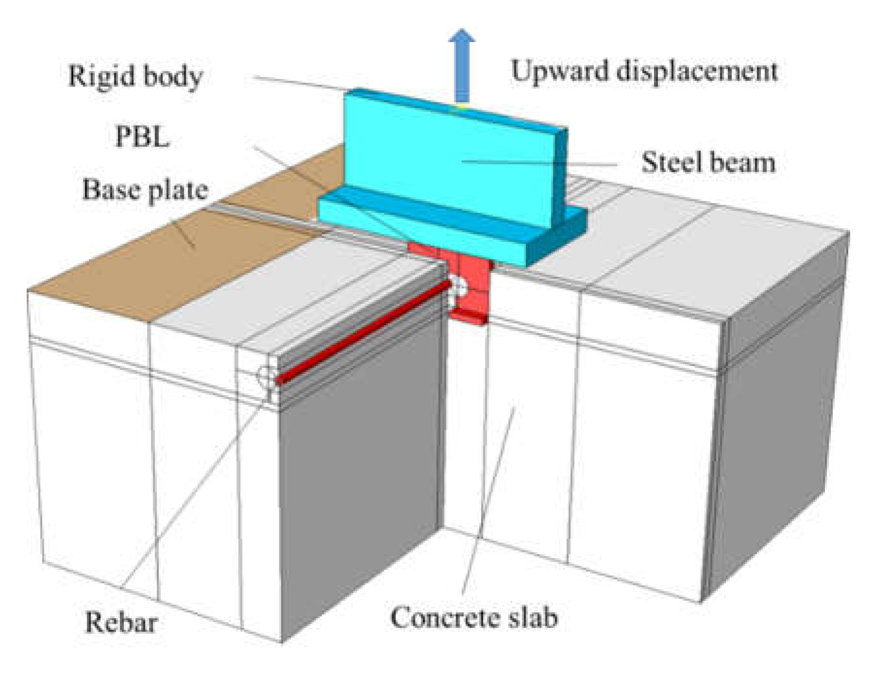
Figure 9.
Finite element type and mesh.
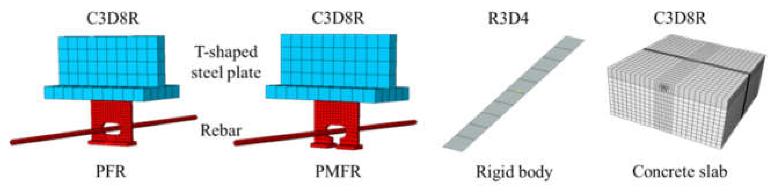
Figure 10.
Interaction and boundary conditions.
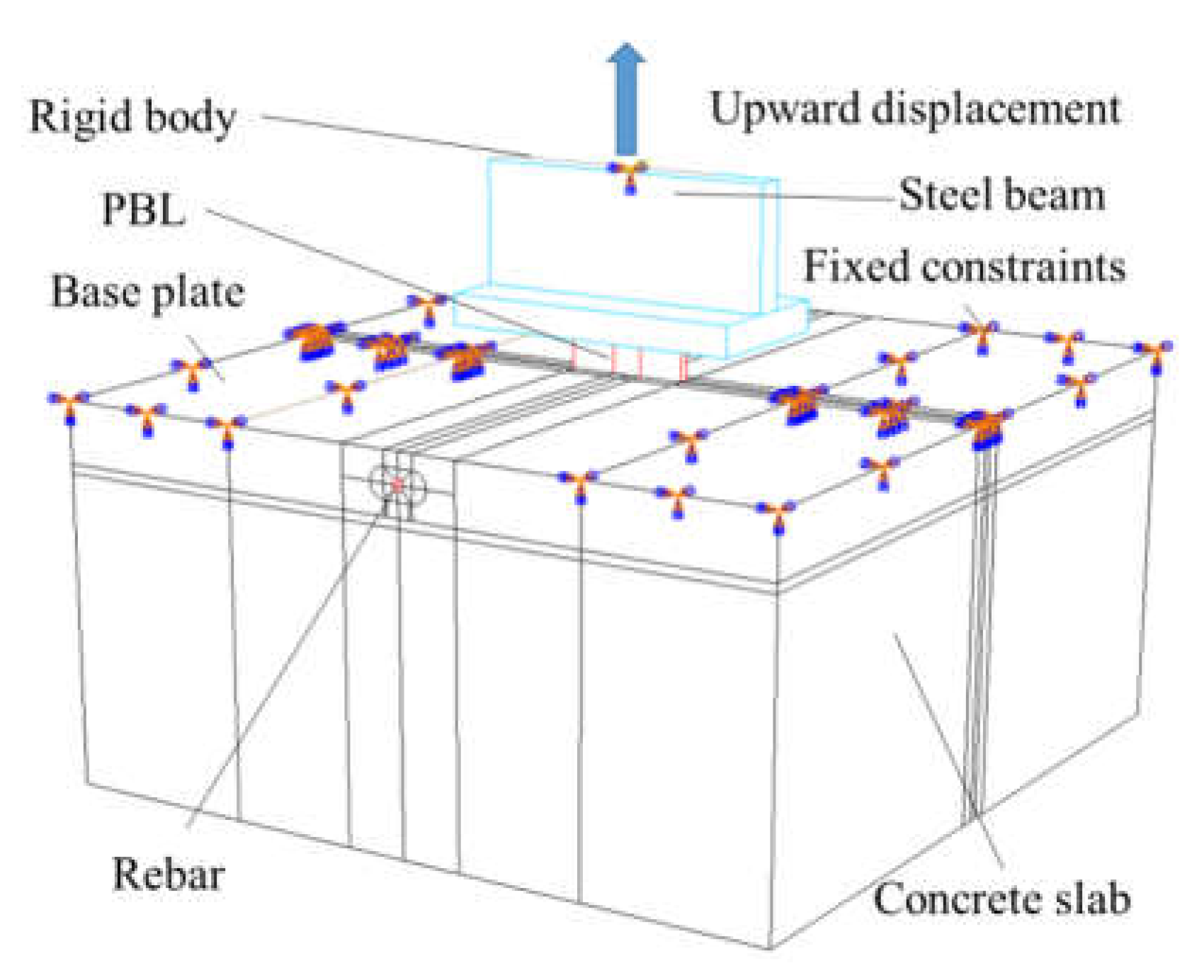
Figure 11.
Material constitution of concrete. (a) Compression; (b) tension.
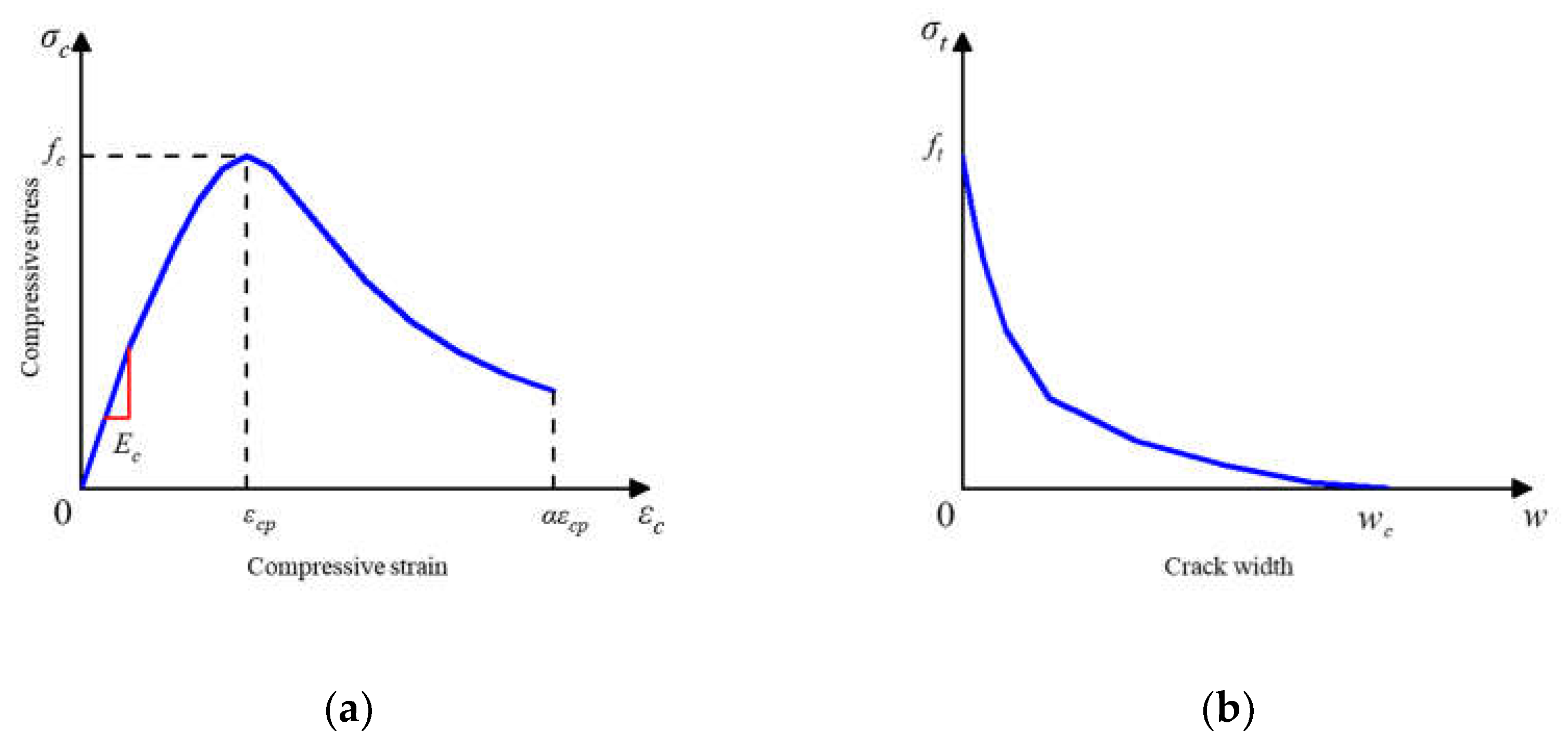
Figure 12.
Material constitution of steel.
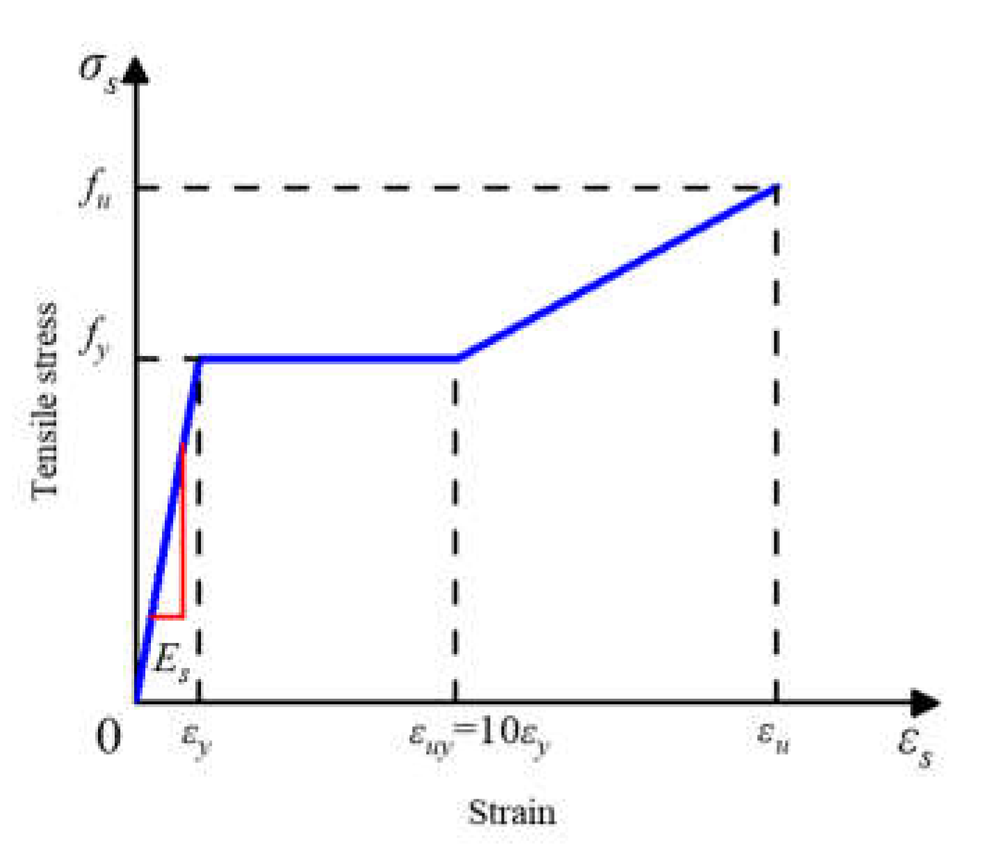
Figure 13.
Tested and analyzed failure modes. (a) Concrete damage verification; (b) perfobond rib fracture verification.
Figure 13.
Tested and analyzed failure modes. (a) Concrete damage verification; (b) perfobond rib fracture verification.
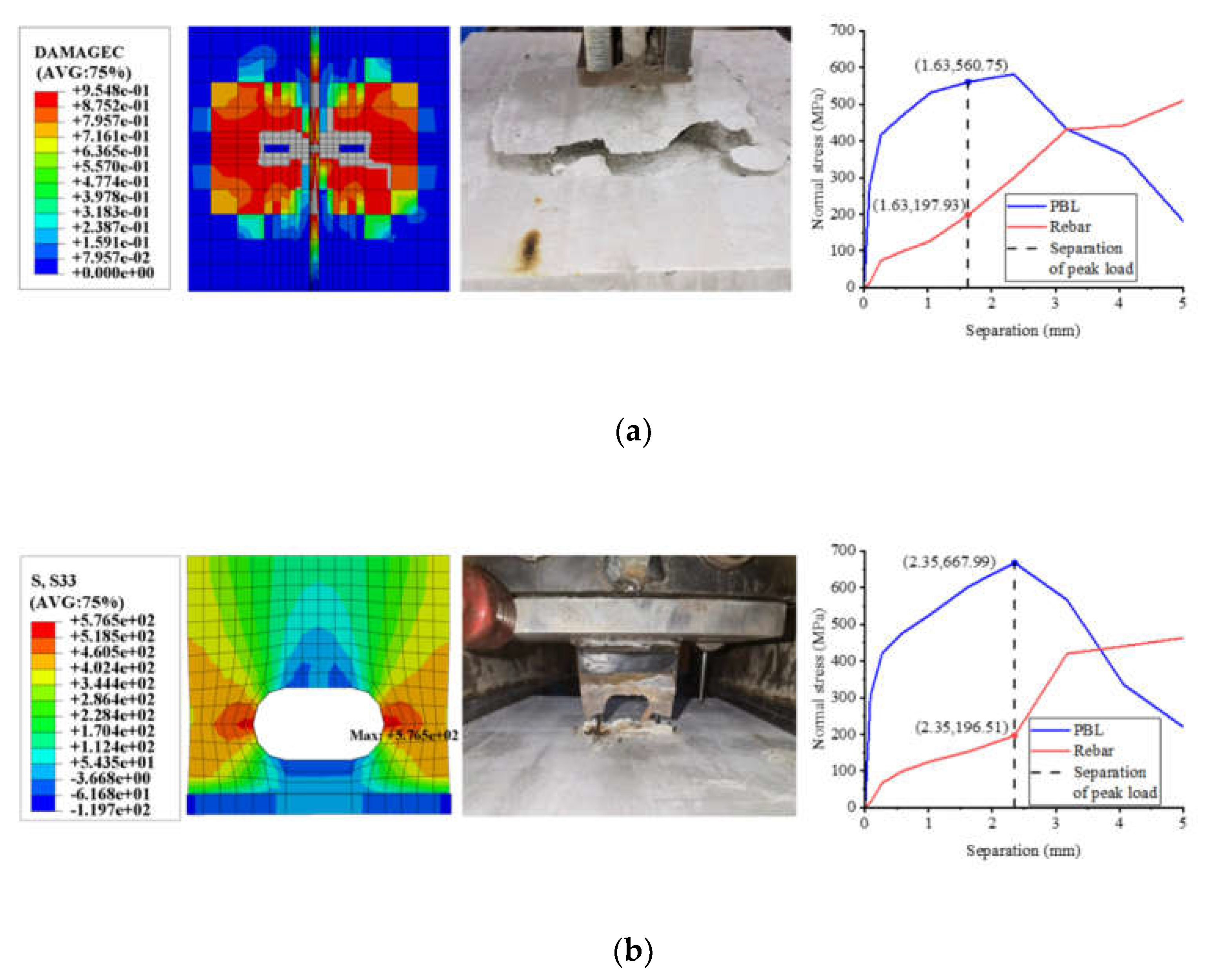
Figure 14.
Tested and analyzed load–slip curves. (a) T-perfobond; (b) notched T-perfobond.
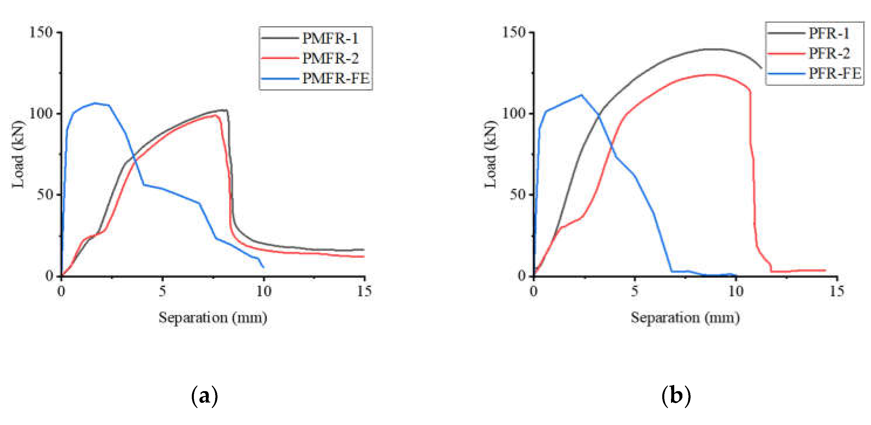
Figure 15.
Influence of flange thickness. (a) Load–separation curves; (b) influence analysis; (c) failure mode.
Figure 15.
Influence of flange thickness. (a) Load–separation curves; (b) influence analysis; (c) failure mode.
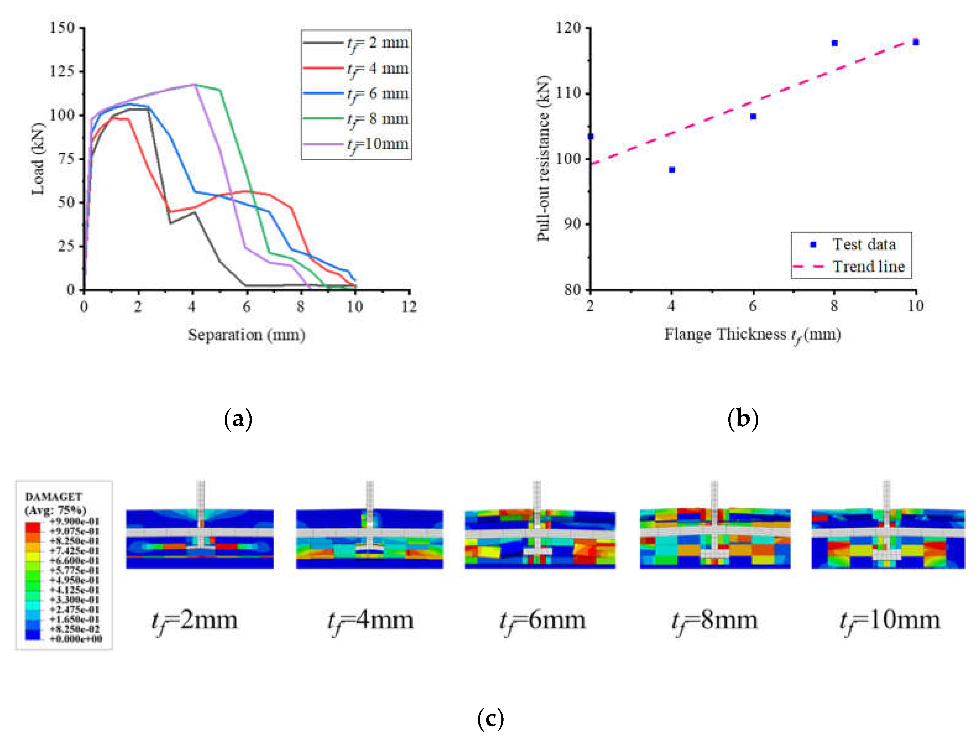
Figure 16.
Influence of flange width. (a) Load–separation curves; (b) influence analysis; (c) failure mode.
Figure 16.
Influence of flange width. (a) Load–separation curves; (b) influence analysis; (c) failure mode.
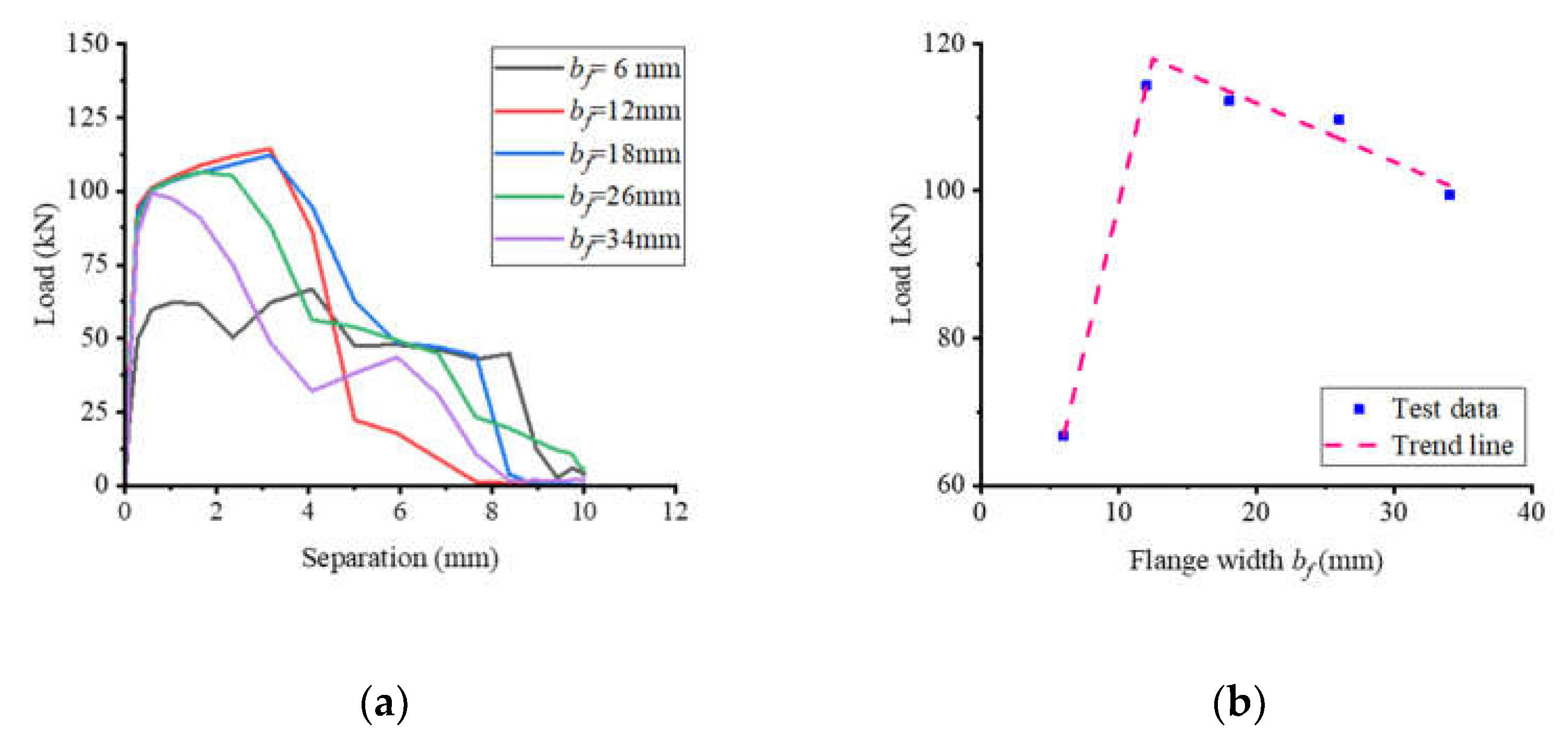
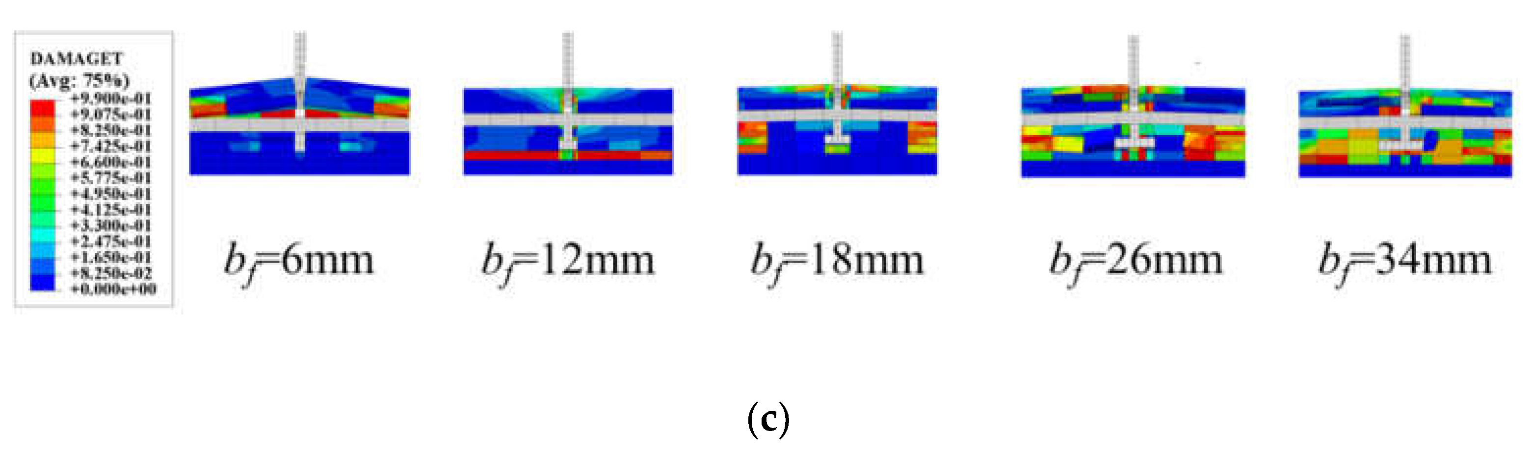
Figure 17.
Influence of cut width. (a) Load–separation curves; (b) influence analysis; (c) failure mode.
Figure 17.
Influence of cut width. (a) Load–separation curves; (b) influence analysis; (c) failure mode.
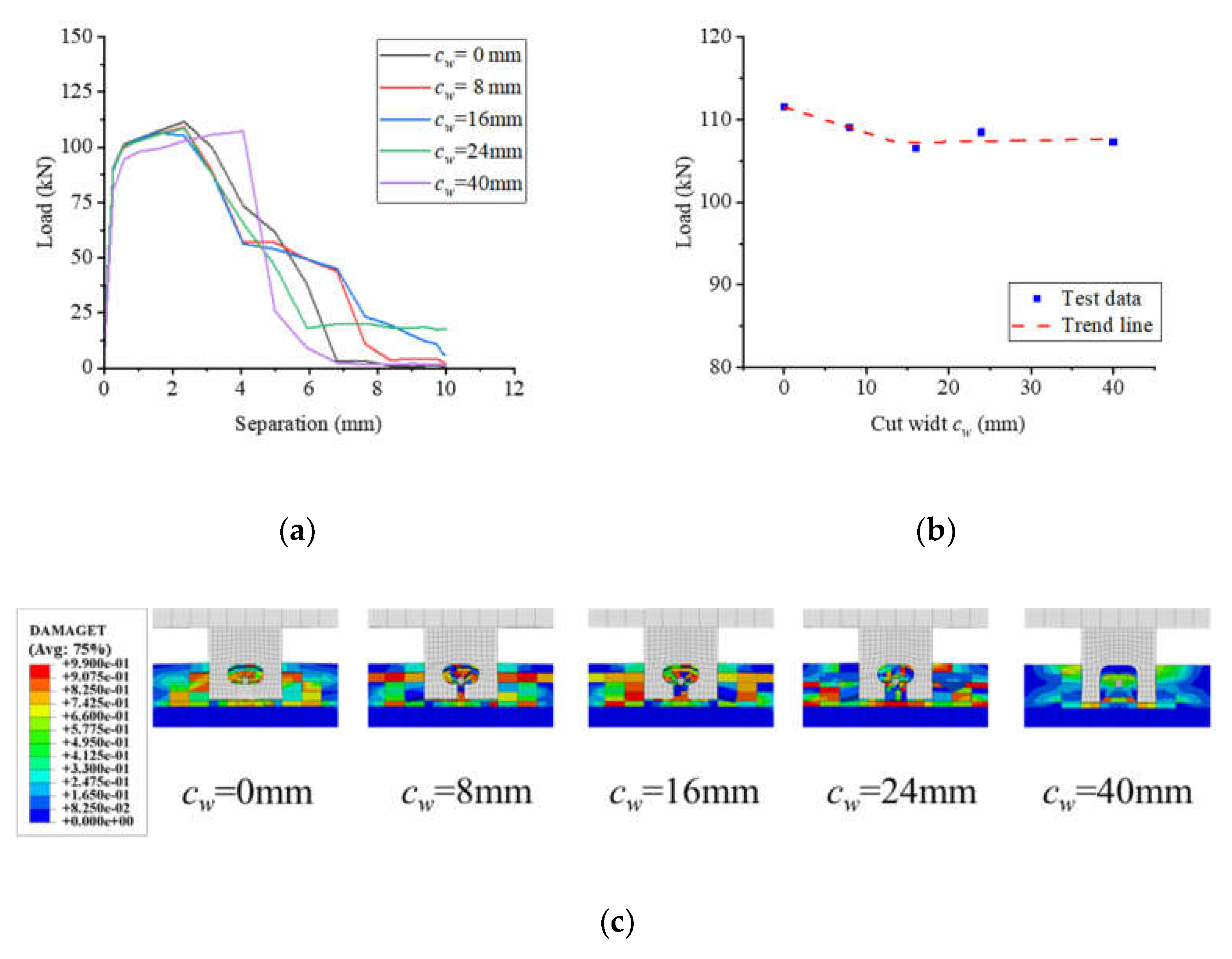
Figure 18.
Influence of hole height. (a) Load–separation curves; (b) influence analysis; (c) failure mode.
Figure 18.
Influence of hole height. (a) Load–separation curves; (b) influence analysis; (c) failure mode.
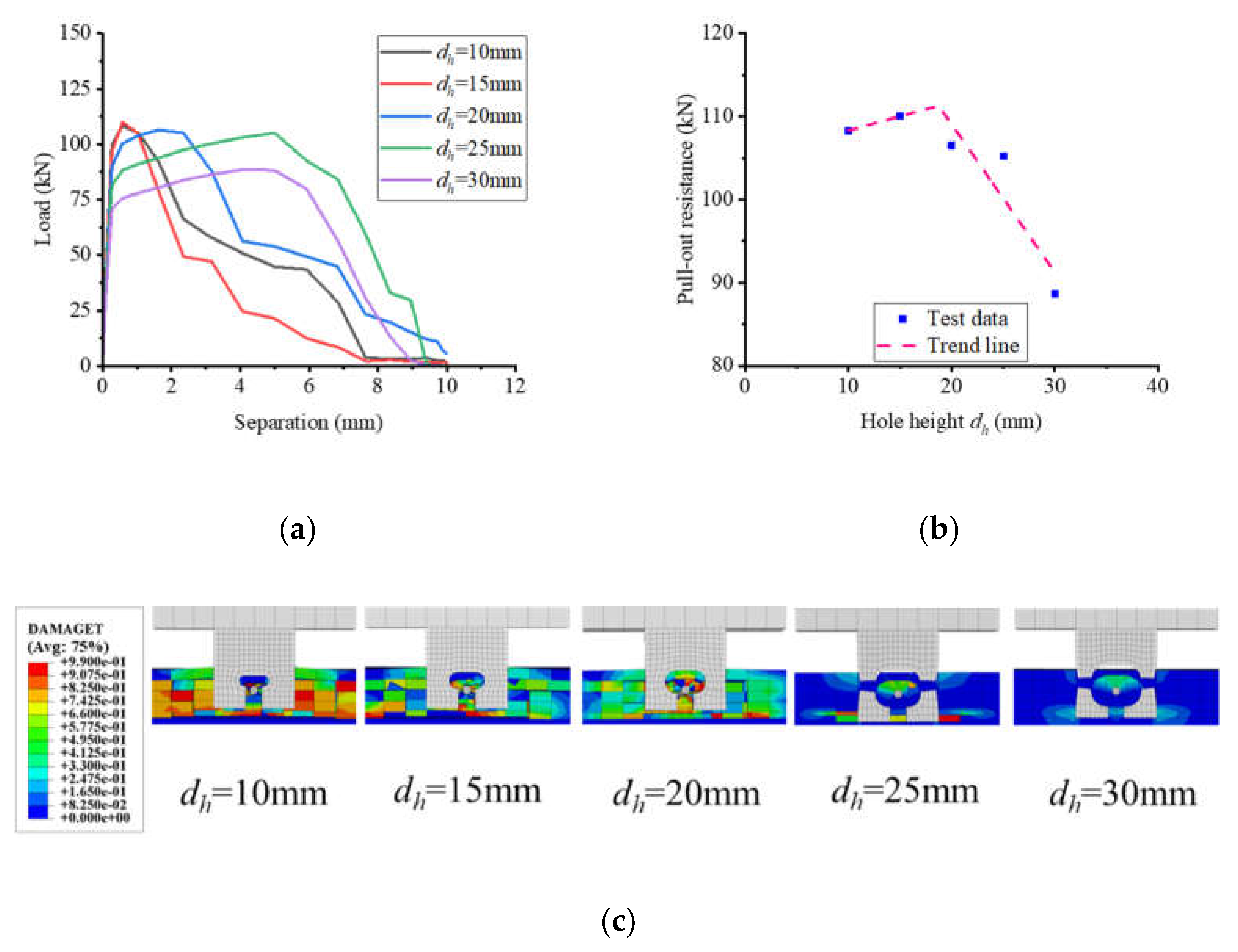
Figure 19.
Influence of hole length. (a) Load–separation curves; (b) influence analysis; (c) failure mode.
Figure 19.
Influence of hole length. (a) Load–separation curves; (b) influence analysis; (c) failure mode.
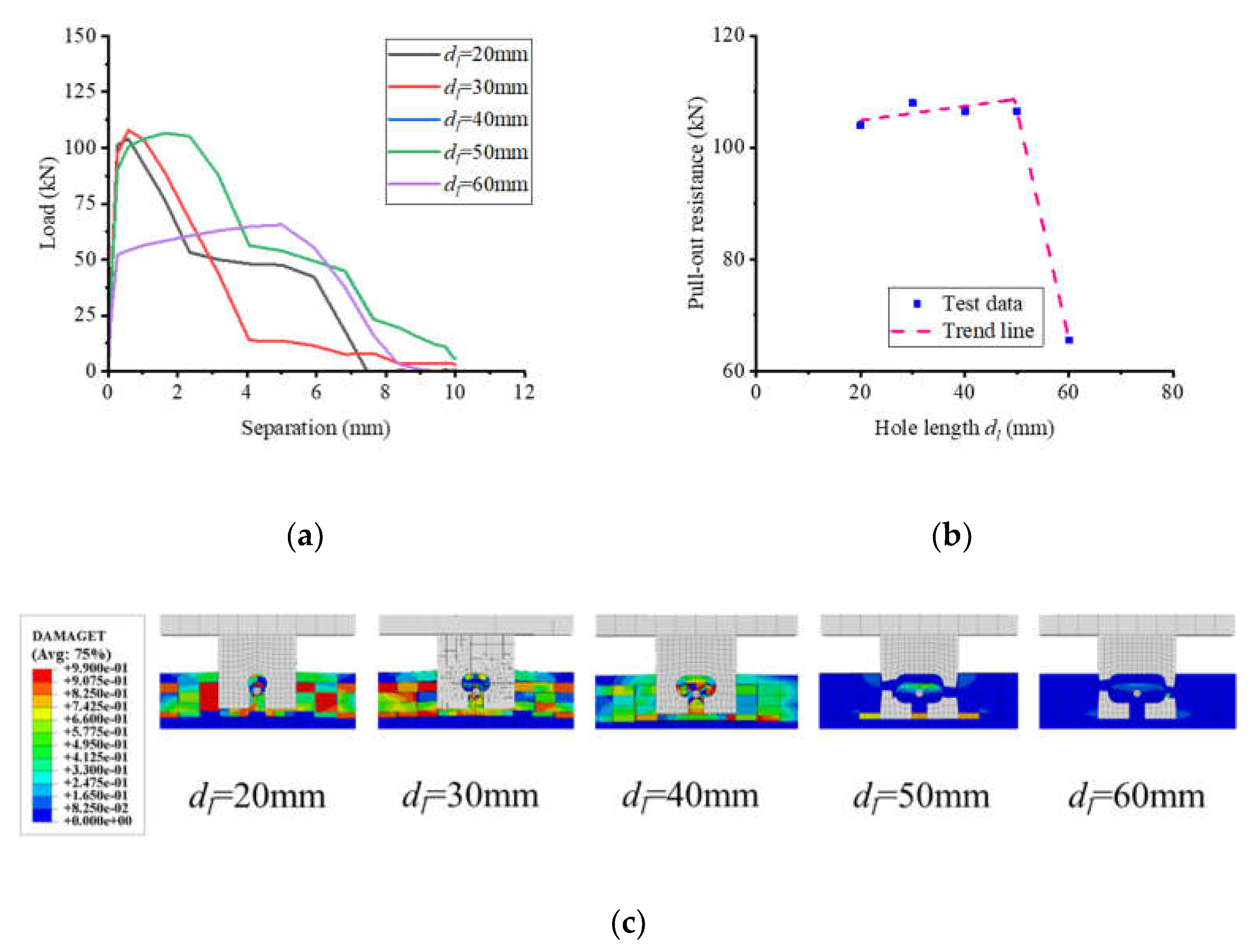
Figure 20.
Influence of perfobond thickness. (a) Load–separation curves; (b) influence analysis; (c) failure mode.
Figure 20.
Influence of perfobond thickness. (a) Load–separation curves; (b) influence analysis; (c) failure mode.
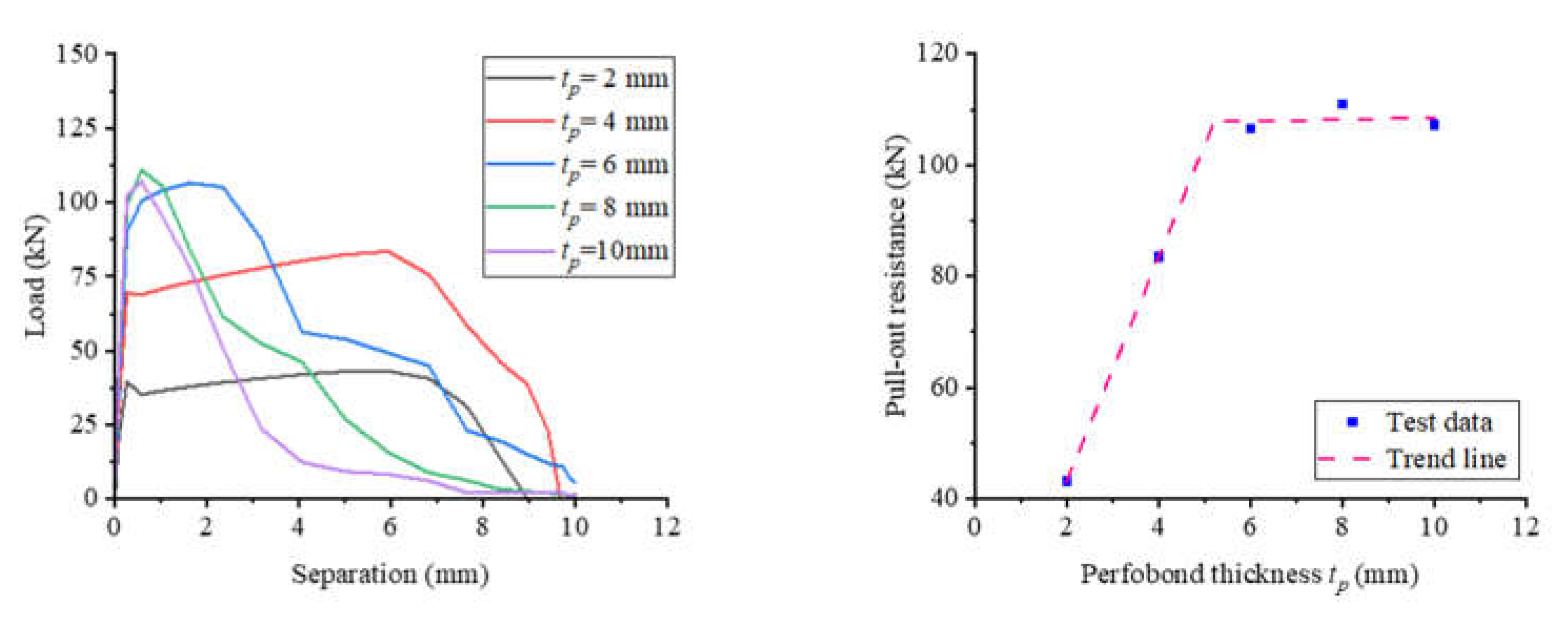
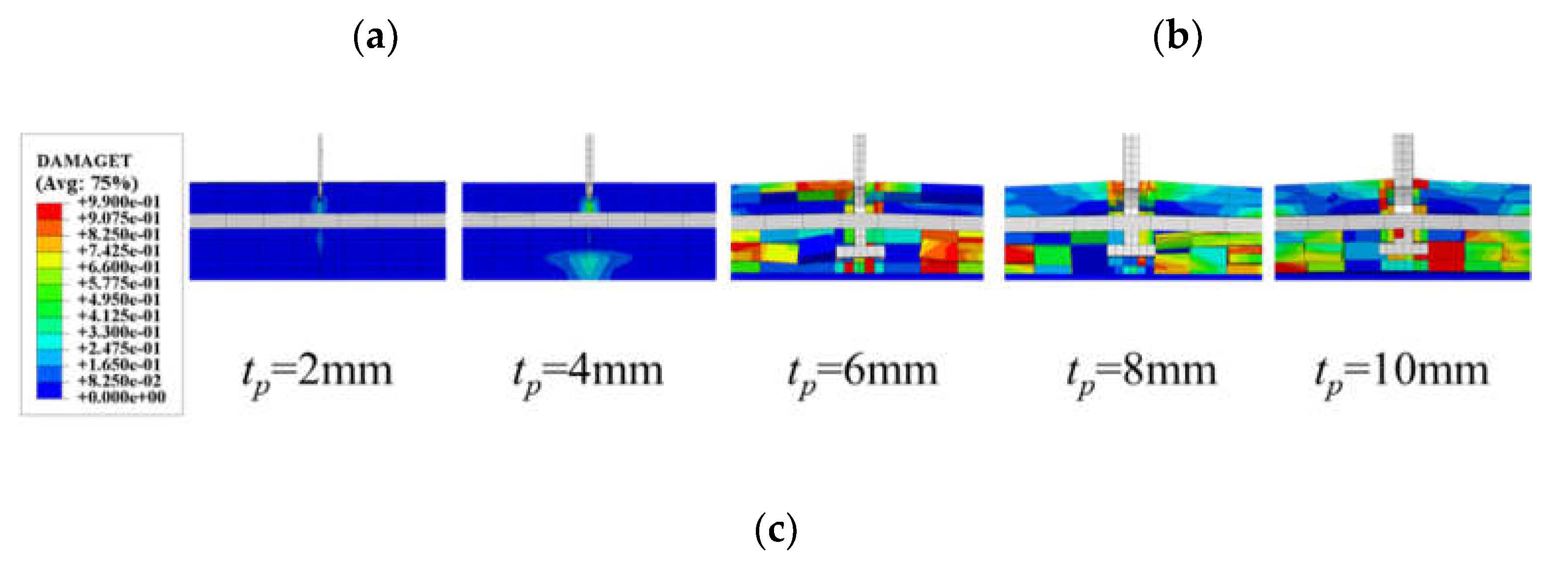
Figure 21.
Influence of perfobond length. (a) Load–separation curves; (b) influence analysis; (c) failure mode.
Figure 21.
Influence of perfobond length. (a) Load–separation curves; (b) influence analysis; (c) failure mode.
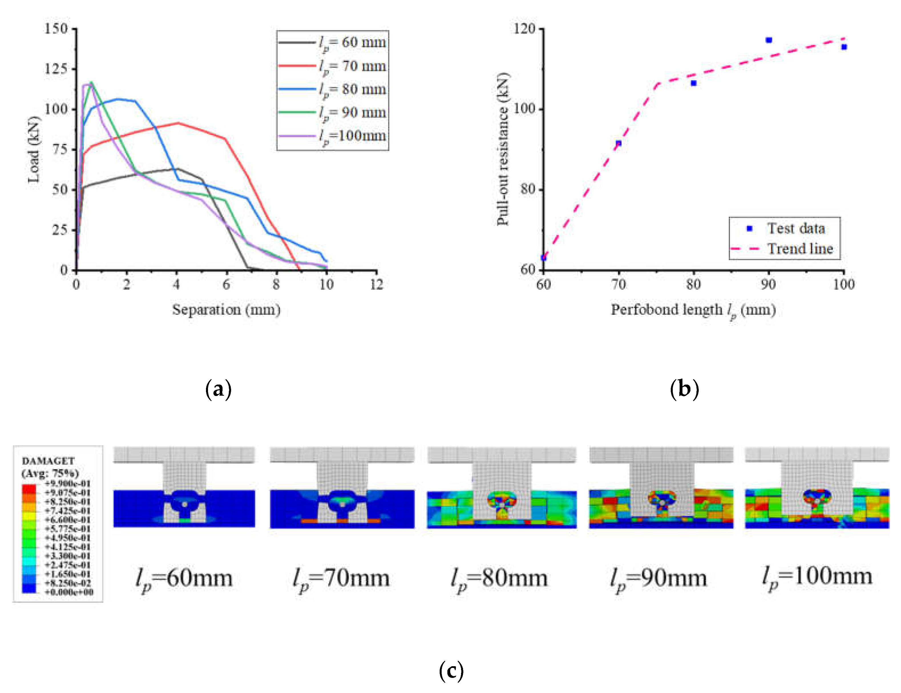
Figure 22.
Influence of rebar diameter. (a) Load–separation curves; (b) influence analysis; (c) failure mode.
Figure 22.
Influence of rebar diameter. (a) Load–separation curves; (b) influence analysis; (c) failure mode.
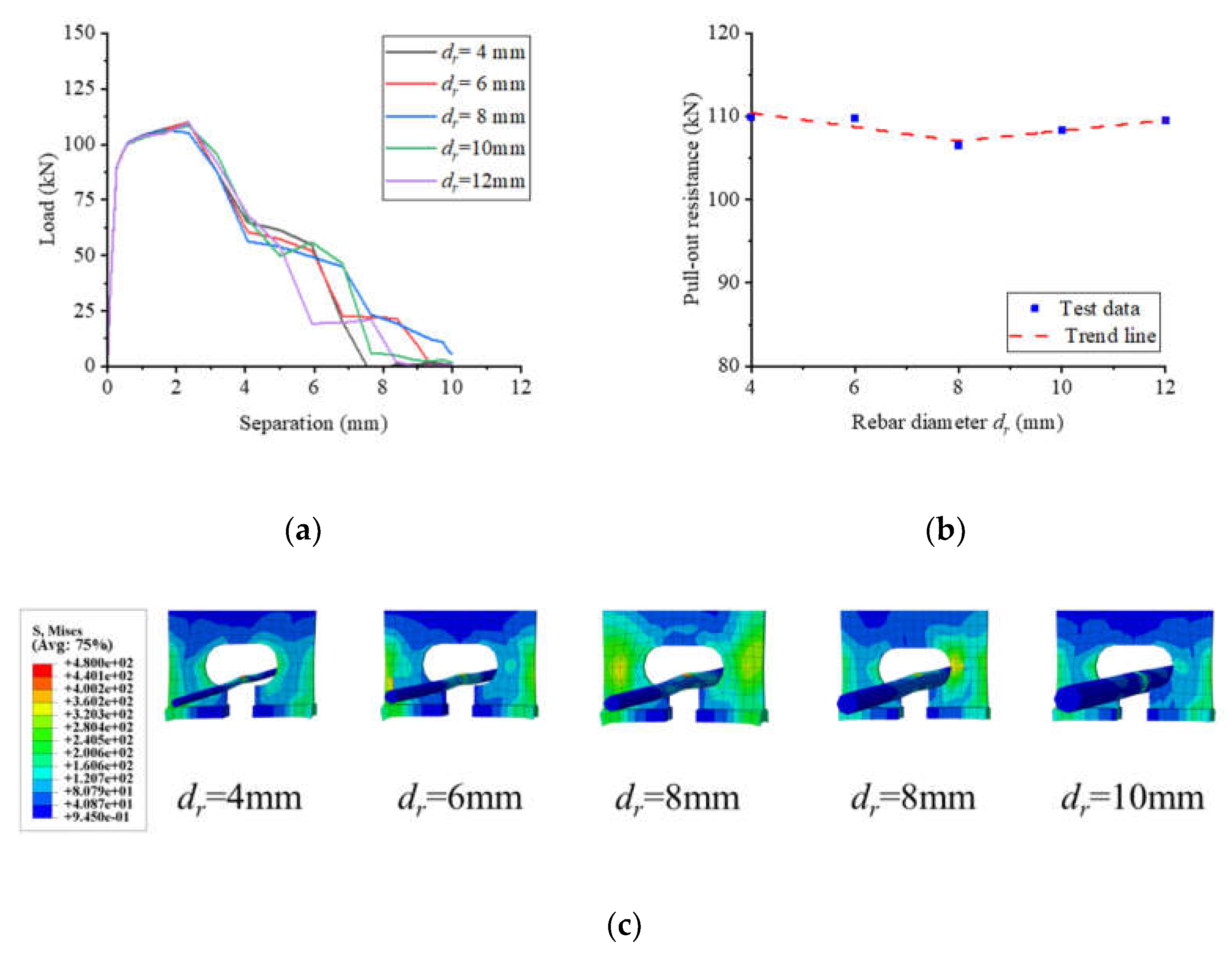
Figure 23.
Influence of concrete strength. (a) Load–separation curves; (b) influence analysis; (c) failure mode.
Figure 23.
Influence of concrete strength. (a) Load–separation curves; (b) influence analysis; (c) failure mode.
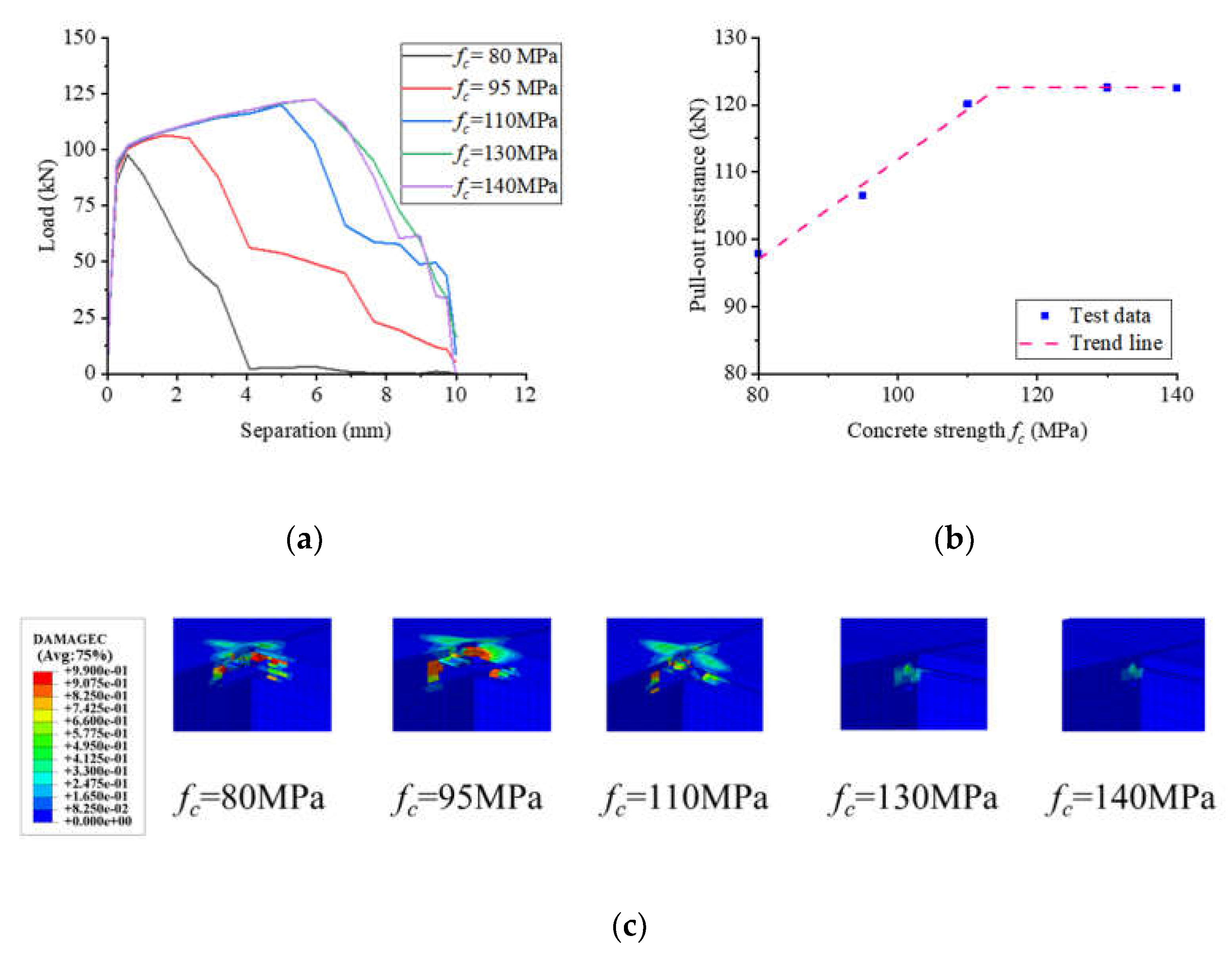
Figure 24.
Influence of rebar strength. (a) Load–separation curves; (b) influence analysis; (c) failure mode.
Figure 24.
Influence of rebar strength. (a) Load–separation curves; (b) influence analysis; (c) failure mode.
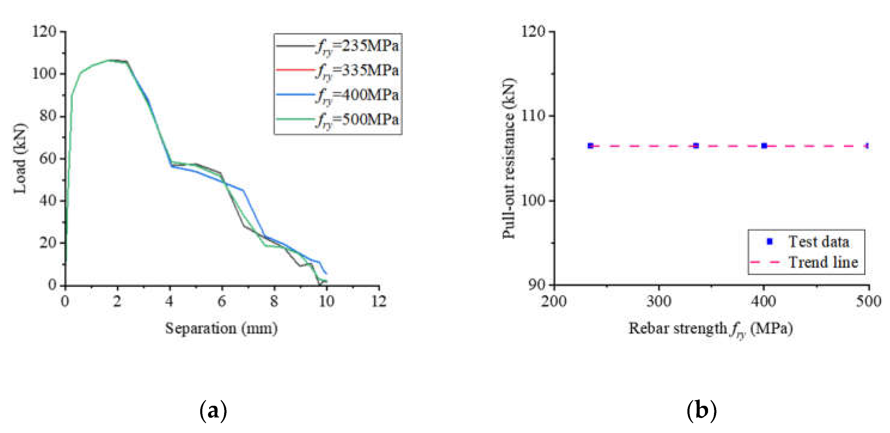
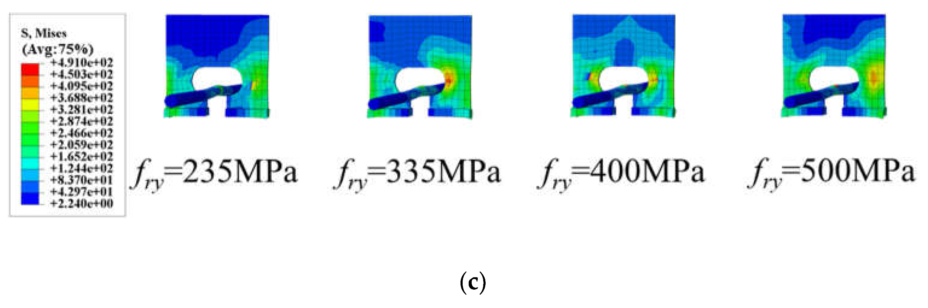
Figure 25.
Influence of steel strength. (a) Load–separation curves; (b) influence analysis; (c) failure mode.
Figure 25.
Influence of steel strength. (a) Load–separation curves; (b) influence analysis; (c) failure mode.
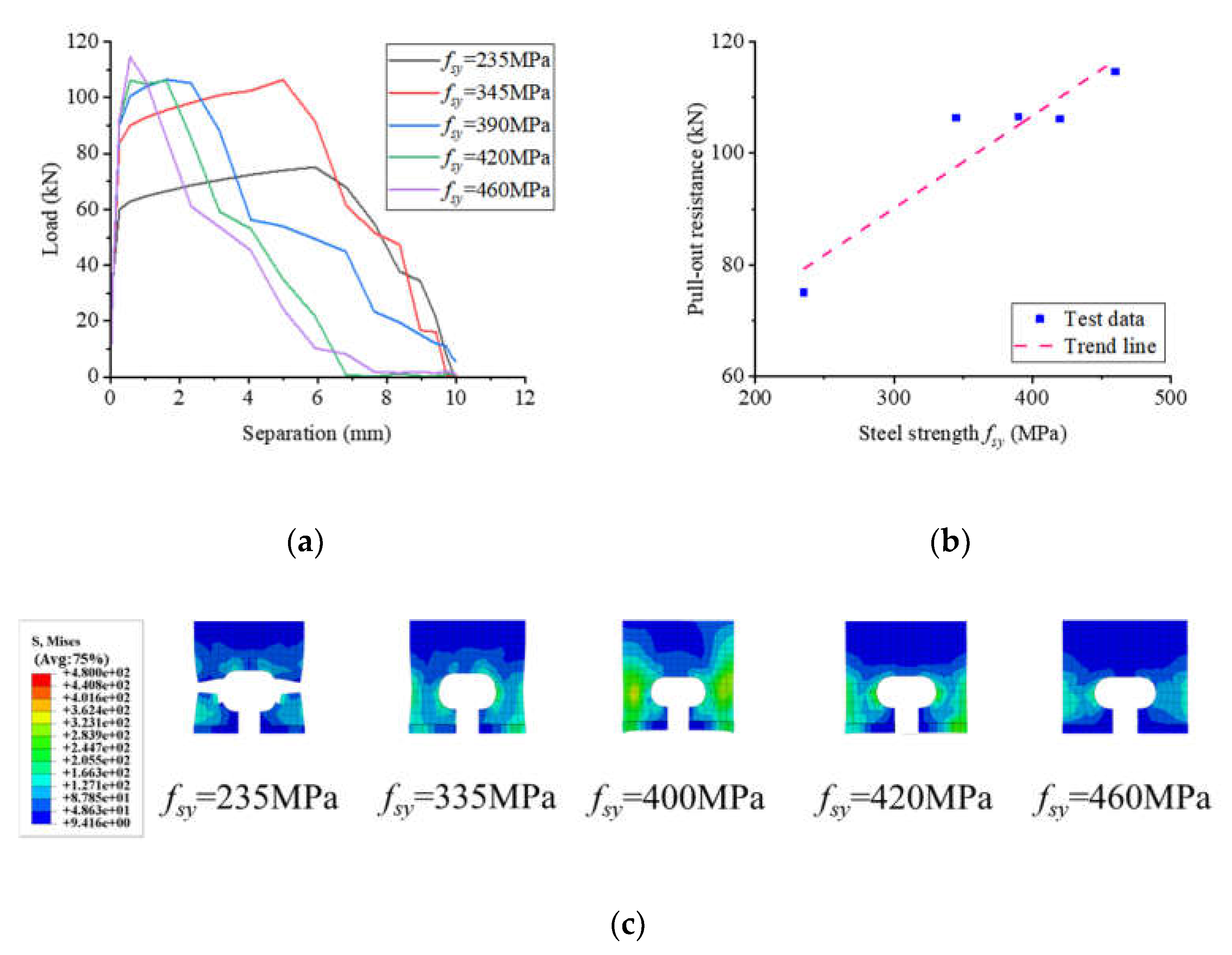
Figure 27.
Comparison of calculation and tested results. (a) Equations (6) and (7); (b) Equations (6) and (8).
Figure 27.
Comparison of calculation and tested results. (a) Equations (6) and (7); (b) Equations (6) and (8).
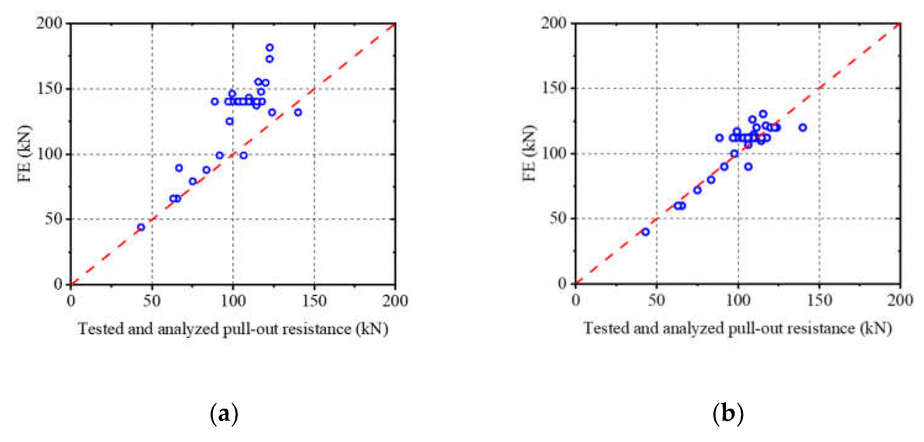

Table 1.
Model grouping and experimental results.
| Specimen | dl(mm) | dh(mm) | dr(mm) | tp(mm) | tf(mm) | bf(mm) | lp(mm) | cw(mm) | Tu(kN) | Tu,avg(kN) |
|---|---|---|---|---|---|---|---|---|---|---|
| PFR–1 | 40 | 20 | 8 | 6 | 6 | 26 | 80 | 0 | 140 | 132.0 |
| PFR–2 | 40 | 20 | 8 | 6 | 6 | 26 | 80 | 0 | 124 | |
| PMFR–1 | 40 | 20 | 8 | 6 | 6 | 26 | 80 | 16 | 102 | 100.5 |
| PMFR–2 | 40 | 20 | 8 | 6 | 6 | 26 | 80 | 16 | 99 |
Table 3.
Generalization of parametric models.
| Model |
tf (mm) |
bf (mm) |
cw (mm) |
dh (mm) |
dl (mm) |
tp (mm) |
lp (mm) |
dr (mm) |
fc (MPa) |
fry (MPa) |
fsy (MPa) |
Tu (kN) |
|---|---|---|---|---|---|---|---|---|---|---|---|---|
| TF-02 | 2 | 26 | 16 | 20 | 40 | 6 | 80 | 8 | 95 | 400 | 390 | 103.44 |
| TF-04 | 4 | 26 | 16 | 20 | 40 | 6 | 80 | 8 | 95 | 400 | 390 | 98.39 |
| TF-06 | 6 | 26 | 16 | 20 | 40 | 6 | 80 | 8 | 95 | 400 | 390 | 106.51 |
| TF-08 | 8 | 26 | 16 | 20 | 40 | 6 | 80 | 8 | 95 | 400 | 390 | 117.64 |
| TF-10 | 10 | 26 | 16 | 20 | 40 | 6 | 80 | 8 | 95 | 400 | 390 | 117.82 |
| BF-06 | 6 | 6 | 16 | 20 | 40 | 6 | 80 | 8 | 95 | 400 | 390 | 66.71 |
| BF-12 | 6 | 12 | 16 | 20 | 40 | 6 | 80 | 8 | 95 | 400 | 390 | 114.31 |
| BF-18 | 6 | 18 | 16 | 20 | 40 | 6 | 80 | 8 | 95 | 400 | 390 | 112.2 |
| BF-26 | 6 | 26 | 16 | 20 | 40 | 6 | 80 | 8 | 95 | 400 | 390 | 106.51 |
| BF-34 | 6 | 34 | 16 | 20 | 40 | 6 | 80 | 8 | 95 | 400 | 390 | 99.43 |
| CW-08 | 6 | 26 | 8 | 20 | 40 | 6 | 80 | 8 | 95 | 400 | 390 | 111.52 |
| CW-12 | 6 | 26 | 12 | 20 | 40 | 6 | 80 | 8 | 95 | 400 | 390 | 109.01 |
| CW-16 | 6 | 26 | 16 | 20 | 40 | 6 | 80 | 8 | 95 | 400 | 390 | 106.51 |
| CW-20 | 6 | 26 | 20 | 20 | 40 | 6 | 80 | 8 | 95 | 400 | 390 | 108.45 |
| CW-24 | 6 | 26 | 24 | 20 | 40 | 6 | 80 | 8 | 95 | 400 | 390 | 107.27 |
| DH-10 | 6 | 26 | 16 | 10 | 40 | 6 | 80 | 8 | 95 | 400 | 390 | 108.3 |
| DH-15 | 6 | 26 | 16 | 15 | 40 | 6 | 80 | 8 | 95 | 400 | 390 | 110.02 |
| DH-20 | 6 | 26 | 16 | 20 | 40 | 6 | 80 | 8 | 95 | 400 | 390 | 106.51 |
| DH-25 | 6 | 26 | 16 | 25 | 40 | 6 | 80 | 8 | 95 | 400 | 390 | 105.19 |
| DH-30 | 6 | 26 | 16 | 30 | 40 | 6 | 80 | 8 | 95 | 400 | 390 | 88.66 |
| DL-20 | 6 | 26 | 16 | 20 | 20 | 6 | 80 | 8 | 95 | 400 | 390 | 103.98 |
| DL-30 | 6 | 26 | 16 | 20 | 30 | 6 | 80 | 8 | 95 | 400 | 390 | 107.93 |
| DL-40 | 6 | 26 | 16 | 20 | 40 | 6 | 80 | 8 | 95 | 400 | 390 | 106.51 |
| DL-50 | 6 | 26 | 16 | 20 | 50 | 6 | 80 | 8 | 95 | 400 | 390 | 106.51 |
| DL-60 | 6 | 26 | 16 | 20 | 60 | 6 | 80 | 8 | 95 | 400 | 390 | 65.55 |
| TP-02 | 6 | 26 | 16 | 20 | 40 | 2 | 80 | 8 | 95 | 400 | 390 | 43.22 |
| TP-04 | 6 | 26 | 16 | 20 | 40 | 4 | 80 | 8 | 95 | 400 | 390 | 83.51 |
| TP-06 | 6 | 26 | 16 | 20 | 40 | 6 | 80 | 8 | 95 | 400 | 390 | 106.51 |
| TP-08 | 6 | 26 | 16 | 20 | 40 | 8 | 80 | 8 | 95 | 400 | 390 | 110.95 |
| TP-10 | 6 | 26 | 16 | 20 | 40 | 10 | 80 | 8 | 95 | 400 | 390 | 107.13 |
| LP-60 | 6 | 26 | 16 | 20 | 40 | 6 | 60 | 8 | 95 | 400 | 390 | 63.1 |
| LP-70 | 6 | 26 | 16 | 20 | 40 | 6 | 70 | 8 | 95 | 400 | 390 | 91.62 |
| LP-80 | 6 | 26 | 16 | 20 | 40 | 6 | 80 | 8 | 95 | 400 | 390 | 106.51 |
| LP-90 | 6 | 26 | 16 | 20 | 40 | 6 | 90 | 8 | 95 | 400 | 390 | 117.26 |
| LP-100 | 6 | 26 | 16 | 20 | 40 | 6 | 100 | 8 | 95 | 400 | 390 | 115.54 |
| DR-04 | 6 | 26 | 16 | 20 | 40 | 6 | 80 | 4 | 95 | 400 | 390 | 109.9 |
| DR-06 | 6 | 26 | 16 | 20 | 40 | 6 | 80 | 6 | 95 | 400 | 390 | 109.77 |
| DR-08 | 6 | 26 | 16 | 20 | 40 | 6 | 80 | 8 | 95 | 400 | 390 | 106.51 |
| DR-10 | 6 | 26 | 16 | 20 | 40 | 6 | 80 | 10 | 95 | 400 | 390 | 108.29 |
| DR-12 | 6 | 26 | 16 | 20 | 40 | 6 | 80 | 12 | 95 | 400 | 390 | 109.53 |
| FC-80 | 6 | 26 | 16 | 20 | 40 | 6 | 80 | 8 | 80 | 400 | 390 | 97.83 |
| FC-95 | 6 | 26 | 16 | 20 | 40 | 6 | 80 | 8 | 95 | 400 | 390 | 106.51 |
| FC-110 | 6 | 26 | 16 | 20 | 40 | 6 | 80 | 8 | 110 | 400 | 390 | 120.13 |
| FC-130 | 6 | 26 | 16 | 20 | 40 | 6 | 80 | 8 | 130 | 400 | 390 | 122.59 |
| FC-140 | 6 | 26 | 16 | 20 | 40 | 6 | 80 | 8 | 140 | 400 | 390 | 122.57 |
| RY-235 | 6 | 26 | 16 | 20 | 40 | 6 | 80 | 8 | 95 | 235 | 390 | 106.51 |
| RY-335 | 6 | 26 | 16 | 20 | 40 | 6 | 80 | 8 | 95 | 335 | 390 | 106.51 |
| RY-400 | 6 | 26 | 16 | 20 | 40 | 6 | 80 | 8 | 95 | 400 | 390 | 106.51 |
| RY-500 | 6 | 26 | 16 | 20 | 40 | 6 | 80 | 8 | 95 | 500 | 390 | 106.51 |
| SY-235 | 6 | 26 | 16 | 20 | 40 | 6 | 80 | 8 | 95 | 400 | 235 | 75.1 |
| SY-345 | 6 | 26 | 16 | 20 | 40 | 6 | 80 | 8 | 95 | 400 | 345 | 106.38 |
| SY-390 | 6 | 26 | 16 | 20 | 40 | 6 | 80 | 8 | 95 | 400 | 390 | 106.51 |
| SY-420 | 6 | 26 | 16 | 20 | 40 | 6 | 80 | 8 | 95 | 400 | 420 | 106.11 |
| SY-460 | 6 | 26 | 16 | 20 | 40 | 6 | 80 | 8 | 95 | 400 | 460 | 114.61 |
Disclaimer/Publisher’s Note: The statements, opinions and data contained in all publications are solely those of the individual author(s) and contributor(s) and not of MDPI and/or the editor(s). MDPI and/or the editor(s) disclaim responsibility for any injury to people or property resulting from any ideas, methods, instructions or products referred to in the content. |
© 2024 by the authors. Licensee MDPI, Basel, Switzerland. This article is an open access article distributed under the terms and conditions of the Creative Commons Attribution (CC BY) license (http://creativecommons.org/licenses/by/4.0/).
Copyright: This open access article is published under a Creative Commons CC BY 4.0 license, which permit the free download, distribution, and reuse, provided that the author and preprint are cited in any reuse.