
Submitted:
25 June 2024
Posted:
26 June 2024
You are already at the latest version
Abstract
Potential permanent magnet (Fe0.7Co0.3)2B has large saturation magnetization and high Curie temperature but a moderate magnetocrystalline anisotropy (MCA) and displays relatively low coercivity. One way to improve coercivity is to combine the contribution from magnetocrystalline- and magnetic shape anisotropy by preparing (Fe0.7Co0.3)2B nanowires. We study the effect of size, morphology, and surface defect on the hard magnetic properties of nanowires using micromagnetic simulation. The hard magnetic properties of (Fe0.7Co0.3)2B nanowire bonded magnet have been estimated, including the role of inter-wire magnetostatic interaction. By considering the existence of local reduction of MCA energy up to 30% on the surface layer of nanowires, the anisotropic bonded magnet with 65% vol. of (Fe0.7Co0.3)2B nanowires displays typical magnetic properties of remanence Br=8.4 kG, coercivity Hci=9.9 kOe, and maximum energy product (BH)m=17.8 MGOe. Developing effective technology for synthesizing nanowires and fabricating corresponding bonded magnets is promising for manufacturing practical magnets based on magnetic phase with relatively low or moderate MCA, such as (Fe0.7Co0.3)2B.
Keywords:
magnetic anisotropy
; coercivity
; micromagnetic simulation
; nanowire
; Fe-Co-B
1. Introduction
The high-performance permanent magnet market is almost wholly occupied by Nd-Fe-B and Sm-Co rare earth (RE) alloys used in many green energy fields, including electric vehicles and wind power generators [1,2]. The growth of RE magnet market results in a supply and demand bottleneck for critical RE metals such as Pr, Nd, Dy, and Tb. Hence, the RE-free magnets have attracted more research attention in recent years [3,4,5]. Among the candidate materials for RE-free magnets, Fe-based compounds such as Fe-Co-B, Fe-Co-P, Fe-N, etc., are of great interest from resource sustainability perspective [6,7,8,9,10].
The tetragonal phase (Fe1−xCox)2B (0.1 ≤ x ≤ 0.5) has an easy-axis magnetocrystalline anisotropy (MCA) with a peak value at x = 0.3 (MCA constant, K1 = 4.1 Merg/cm3, or magnetocrystalline anisotropy field, HMCA=7.8 kOe) at room temperature [10,11]. (Fe0.7Co0.3)2B also has a large magnetization (Js=13 kG) at room temperature and a high Curie temperature of 660 °C. Despite the good intrinsic magnetic properties of (Fe0.7Co0.3)2B [12,13,14,15,16], the experimentally obtained coercivity is rather low and less than 100 Oe [14]. The low coercivity prevents Fe-Co-B from being used in practical applications. Kim et al. reported that doping heavy elements of Re can improve the coercivity of (Fe, Co, Re)2B to about 900 Oe.[15]
One way to enhance the coercivity of (Fe0.7Co0.3)2B is to take advantage of magnetic shape anisotropy (MSA) by controlling the particle sizes and shapes, as done for Alnico permanent magnets. Researchers developed nano-structural Alnico 80 years ago, where the magnetic anisotropy is mainly from shape magnetic anisotropy (Ks) of the needle-shaped ferromagnetic Fe-Co precipitates distributed in a non-magnetic matrix phase of Ni-Al [17,18]. The needle-like Fe-Co particles have a 10-50 nm diameter and can be several hundred to one thousand nanometers long [17,18]. Magnetic nanowires have been studied intensively in recent years [19,20,21]. Under proper synthesis conditions, the hexagonal Cobalt nanowires can be made as single crystals, each with a single magnetic domain structure having a <001> crystallographic axis oriented along the length of the particles [21,22,23]. This gives rise to a uniaxial MCA (Kc) direction that coincides with the MSA (Ks) in the cobalt nanowires and results in large effective anisotropy (Keff), i.e., Keff=Kc+ Ks. Cobalt nanowires with a diameter (d) of 15 nm and a length (l) of 200 nm displays a coercivity of about 10 kOe, which is higher than its theoretical magnetocrystalline anisotropy field (Hk=7.6 kOe) [22]. The optimized bonded magnet of cobalt nanowire shows magnetic remanence Br=9.5 kG, coercivity Hci= 9.6 kOe, and maximum energy product (BH)m= 20 MGOe.[24] However, the high cost of cobalt prevents it from being a practical magnet. It was reported that Fe2B nanowires with a diameter of about 30 nm can be deposited onto a nickel foam via a simple one-step chemical reduction in an externally applied magnetic field [25]. It is also found that the Co-Fe-B nanowires with a diameter of 175 nm and a length of 6-14 µm can be synthesized using electrodeposition with a nano-porous aluminate template [26]. Unfortunately, the array of the Co-Fe-B nanowire shows a typical coercivity of 200 Oe due to the nanowires' large size [26]. These results indicate that the Fe-Co-B nanowires can be synthesized, encouraging us to investigate the coercivity of (Fe0.7Co0.3)2B nanowires and the potential magnetic performance of the bonded magnets prepared with these nanowires.
In this work, we perform a micromagnetic simulation to elucidate the correlation of coercivity with the size, morphology, and surface defect of (Fe0.7Co0.3)2B nanowires. The extrinsic magnetic properties, including remanence, Br, coercivity Hci, and maximum energy product (BH)m, have also been calculated as a function of packing fraction in (Fe0.7Co0.3)2B nanowire bonded magnet. Finally, the challenge and potential pathway for developing nanowire-based magnets have been discussed.
2. Computational Method and Details
The micromagnetic simulation is based on Landau–Lifshitz–Gilbert equation (LLG) and has been widely applied to simulate the magnetic properties of soft and hard magnets [27,28,29]. The micromagnetic simulations were done using a finite difference GPU micromagnetic code, MuMax3.[30,31] Here, the finite-difference cell size is 1 nm×1 nm×1 nm for all the calculations. The magnetic field step for calculating the magnetic hysteresis loop is 1 mT. The total energy minimization was performed using a conjugate gradient method with a converge criterion of normalized magnetization change less than 10-6. The materials parameters of (Fe0.7Co0.3)2B for micromagnetic simulation are derived from experiments [10]. The magnetization (Ms), magneto-crystalline anisotropy constant (K1), and exchange constant (Aex) are 1.035 kG, 4.1 Merg/cm3, and 12×10-7erg/cm, respectively.
3. Results
3.1. Micromagnetic Simulation of Coercivity in (Fe0.7Co0.3)2B Nanowires
3.1.1. Coercivity of Defect-Free (Fe0.7Co0.3)2B Nanowires
As a starting point, we use micromagnetic simulation to investigate the effect of size and morphology on the coercivity of the ideal (Fe0.7Co0.3)2B nanowires without any surface defect. Two typical nanowire shapes, prolate spheroid (s-nanowire) and cylinder (c-nanowire), are considered. The uniformly magnetized spheroid generates a uniform demagnetizing field, i.e., the demagnetizing field (Hd) is homogeneous for s-nanowire, while it is non-uniform for c-nanowire. Theoretically, the maximum effective magnetic anisotropy field can be up to 14.3 kOe for an ideal single crystal and a single magnetic domain (Fe0.7Co0.3)2B nanowire due to the contributions of MCA- (Hmca=7.8 kOe) and MSA (Hmsa=1/2Js=6.5 kOe).
As shown in Figure 1, the c-nanowires (Fe0.7Co0.3)2B with a diameter of 32 nm (black solid sphere) show a coercive field slightly higher than its theoretical magnetocrystalline anisotropic field (7.8 kOe) as the ratio between its length and diameter (l/d) is higher than 2, which is almost twice the value for l/d=1 (4.3 kOe). Further, an increase in the l/d ratio has little effect on coercivity (~8.1 kOe for l/d=16). For the c-nanowire with half the diameter, i.e., 16 nm, the coercivity rapidly increases from 8.1 kOe (l/d=1) to about 10.3 kOe (l/d=2) and remains almost unchanged. It is unsurprising that the c-nanowire of 16 nm has much higher coercivity than that of 32 nm. The critical domain diameter of (Fe0.7Co0.3)2B sphere is about 22 nm, estimated based on the Brown formula D=7.211*(Aex/µ0)1/2/Ms [32]. The parameters D, Aex, and MS are critical domain diameter, exchange constant, and saturation magnetization. A similar observation of higher coercivity in nanowires with diameters less than the critical single domain size was also made for cobalt nanowires [21,22]. For the same diameter (short axis diameter) and l/d ratio (i.e., the ratio between long axis diameter and short axis diameter), the s-nanowires have much higher coercivity than the c-nanowires. For a ratio l/d=16, the s-nanowire with a 16 nm and 32 nm diameter has a coercivity of 14 kOe and 12 kOe, respectively. The calculated coercivity of the 16nm nanowire is almost equal to the sum of the MCA field and the MSA field (14.3 kOe). The similar results are experimentally observed in Co nanowires [22]. These values are higher than that for the c-nanowire with the same l/d ratio by about 40%. As shown in Figure 1, the coercivity values for c-nanowires with 16 nm and 32 nm diameters are 10.5 kOe and 8.2 kOe, respectively. These c-nanowires and s-nanowires can be the building blocks for bonded magnets or other composite permanent magnets.
The big difference in coercivity for the particles with different morphologies is ascribed to their different magnetization and demagnetization field distributions. As shown in Figure 2 (a), the magnetization distributes almost homogeneously along the z-axis for a (Fe0.7Co0.3)2B sphere with a diameter of 20 nm at a magnetic remanent state. The corresponding demagnetization is distributed along the opposite direction inside the sphere (Figure2b). The sphere has a demagnetization factor of 1/3. The (Fe0.7Co0.3)2B s-nanowires with a short axis diameter of 16 nm and a long axis diameter of 256 nm have the MCA easy-axis parallel to the long-axis direction (Figure2c and Figure 2d ). Magnetization distributes homogeneously inside the s-nanowires (Figure 2c). The demagnetization field is stronger at the two ends than that at the middle part (Figure2c). Overall, the demagnetization field aligns opposite to the magnetization direction. It slightly deviates from the z-direction (easy direction) near the surface at the two ends, which are the preferential nucleation sites for the magnetization reversal domains. For the c-nanowires (Fe0.7Co0.3)2B, the magnetization also almost completely aligns along the z-axis (Figure 2e). However, the demagnetization field is strong and deviates more substantially from the z-direction at the two ends of the c-nanowires (Figure 2f) compared to the s-nanowires (Figure 2d). The sharp edge of the c-nanowire ends (cylinder shape) causes strong demagnetization and is a preferential nucleation site for the magnetization reversal domain. It is one of the main reasons for the lower coercivity of the c-nanowire compared to the s-nanowire (Figure 1).
3.1.2. Coercivity of (Fe0.7Co0.3)2B Nanowires with Surface Defect
Our previous work indicated that MCA of (Fe0.7Co0.3)2B is sensitive to structural defects. A fluctuation of cobalt content of 10%, or 1% isotropic lattice strain, or 2% tetragonal distortion reduces MCA energy up to 30% in (Fe0.7Co0.3)2B [33]. Here, we study the effects of local weak MCA on coercivity in s-nanowires and c-nanowires of (Fe0.7Co0.3)2B. As the particle surface has more structural defects than its core, we set up core-shell nanowire models, i.e., the nanowire core has an MCA of bulk single crystal (K=4.1 Merg/cm3). At the same time, the shell (2 nm thickness) surrounding the core has an MCA less than that of the core part by 10-30% (Figure 3).
Figure 4 displays the calculated coercivity as a function of MCA constants of the shell layer, K1 shell in (Fe0.7Co0.3)2B c-nanowire (blue solid line) and s-nanowire (red, dashed line). With a decrease in the K1 shell value from 4.1 to 2.97 Merg/cm3 (i.e., K1 shell =0.7*K1 core), the coercivity of the c-nanowire and s-nanowire decreases almost linearly from 10.5 to 9.4 kOe and from 14.1 to 12.9 kOe, respectively. The local reduction of MCA (nanowire surface) reduces the energy barrier for starting magnetization reversal, decreasing the coercivity.
Table 1 lists the values of the calculated Br, Hci, and (BH)m of some selective s-nanowires and c-nanowires. The remanence remains unchanged for different sized c-nanowires and s-nanowires with- and without- low MCA surface layer. Although the coercivity decreases with reducing K1 shell, the values are still about 9.4 kOe and 13 kOe for c-nanowires and s-nanowires with low MCA surface layers (K1 shell =0.7*K1 core). These values are higher than the theoretical maximum value contributed from MCA (i.e., the MCA field HK=7.8 kOe). In other words, the magnetic shape anisotropy compensates for coercivity reduction due to local MCA fluctuations in the nanowires.
Controlling the nanowire size and morphology can effectively improve the coercivity of the semi-hard magnetic phase lacking strong MCA. All these nanowires have coercivity higher than ½ of Br, and the theoretical (BH)m can be estimated as Br2/4, or 42 MGOe (Table 1). Strictly speaking, the concept of (BH)m is only for bulk magnets. The (BH)m of the nanowires is the upper limit for a bulk magnet made from nanowires. However, assembling these nanowires into bulk magnets while retaining sufficiently high Br, Hci and (BH)m remains challenging.
3.2. Coercivity of (Fe0.7Co0.3)2B Bonded Magnet from Nanowires
The coercivity contributed by MSA, decreases with increasing packing fraction of magnetic particles (or a decrease in the inter-particle distance) due to inter-particle magnetostatic interactions [34,35]. When the distance between neighboring nanowires is zero, the coercivity from MSA disappears. We can prepare bonded magnets using the (Fe0.7Co0.3)2B nanowires as the starting materials to take advantage of the coercivity contributed by magnetic shape anisotropy. The magnetic powder is mixed with binder such as epoxy resin, nylon, etc., and formed into bulk magnets with specific shapes and sizes using methods like compression and injection molding [36]. The non-magnetic binder separates the magnetic nanowires in the bonded magnet, which helps to retain the coercivity originating from MSA. In addition, the non-magnetic binder bonds the magnetic particles together, enabling the necessary mechanical properties for applications.
Although the bonded magnet can partially retain the coercivity from the contribution of magnetic shape anisotropy, the binder dilutes the magnetic powder content which, in turn, decreases magnetic remanence and maximum energy product. To evaluate the potential performance of (Fe0.7Co0.3)2B bonded magnet, we calculate the magnetic properties as a function of the volume fraction of the particles. Four types of (Fe0.7Co0.3)2B magnetic particles are selected as feedstock powder for the bonded magnet: 1) s-nanowire with a diameter of 16 nm and a length of 256 nm; 2) s-nanowire with a diameter of 16 nm and a length of 256 nm, including a surface defect layer of 2 nm with reduced MCA of K1 shell =0.7*K1 core ; 3) c-nanowire with a diameter of 16 nm and a length of 256 nm; 4) c-nanowire with a diameter of 16 nm and a length of 256 nm, including a surface defect layer of 2 nm with reduced MCA of K1 shell =0.7*K1 core. The morphologies of the s-nanowire (3) and c-nanowire (4) with defects were also shown in Figure 3 and described in the previous section. The nanowires are assumed to be magnetically aligned along a single direction and uniformly distributed in the bonded magnets.
The strong magnetostatic interaction between nanowires will reduce the coercivity of the assembly of magnetic nanowires. Several groups have studied the correlation between coercivity and packing fraction for acicular-shaped magnetic particles[37,38,39,40,41]. The coercivity with a contribution of MCA and MSA can be approximated phenomenologically by [41]
Hci(P)=A+B(1-P)
P, A, and B are volume packing fractions, MCA contributed coercivity, and isolated particle coercivity due to MSA, respectively. For isolated particles (P=0), the coercivity is the sum of the parts originating from MCA and MSA. The predicted linear correlation between coercivity and packing fraction from Eq.1 has also been confirmed in cobalt nanowire assemblies from micromagnetic simulations [42]. The coercivity value of several simulated nanowires with K1=0 has been calculated to derive parameter B. The shape, size, magnetization, and exchange parameters of the simulated nanowires are the same as those of nanowires 1, 2, 3, and 4, respectively. The calculated coercivity of the simulated nanowires is entirely contributed by magnetic shape anisotropy (i.e., B). Parameter A can be estimated from the coercivity difference between the actual and simulated nanowires. The calculated parameters A and B are listed in Table 2. The A values differ, but the B values are the same for nanowire-1 and nanowire-2. The result is unsurprising, as nanowires 1 and 2 have the same geometry, size, and magnetic parameters except for MCA constant K1. The parameter A is mainly determined by MCA while B arises from magnetic shape anisotropy. Similar observations are made for nanowire-3 and nanowire-4 (Table 2).
Theoretically, the packing density for orderly packing of ellipsoids is 0.7707 for the particles with an aspect ratio larger than 1.732 [43]. The packing density of circular cylinders with a high aspect ratio is slightly higher than π/ based on geometry analysis [44]. So, we estimate the extrinsic magnetic properties of nanowire bonded magnets with a packing fraction up to 0.7. Figure 5 shows the calculated extrinsic magnetic properties of (Fe0.7Co0.3)2B bonded magnets with different types of particles. As expected, the coercivity decreases while the Br values increase linearly with increasing volume packing fraction. Relative to equation 1 above, the coercivity originating from MCA remains unchanged (A), while the coercivity arising from MSA linearly reduces with increasing magnetic particle volume fraction. The Br values of bonded magnets are the same for different magnetic particles with the same volume fraction since we assume they have the same magnetization. As shown in Figure 5, all Hci values are higher than half of the Br values in these bonded magnets. The magnetic particles are assumed to be aligned entirely along their magnetic easy-axis direction, i.e., a 100 % DOA (degree of alignment), resulting in a demagnetization curve with excellent squareness in the bonded magnet (Figure 6). The (BH)m = (Br)2/4, shows a similar trend, being determined by the volume fraction of the different magnetic nanowires. For 40–70 vol.% c-nanowires with 30% reduced MCA defect shell, the bonded magnets can achieve a Hci value of ~7.3-8.2 kOe and a (BH)m of 6.8-20.6 MGOe.
For the 40–70 vol.% s-nanowire as feedstock, the bonded magnets would have Hci of 9.1-10.5 kOe and a (BH)m of 6.8-20.6 MGOe. In addition to the morphology, structural defect, and volume fraction of the nanowires, the bonded magnet's performance also depends on the nanowire size. Table 3 lists the magnetic properties of several typical nanowire-based bonded magnets in which the (BH)m ranged between 10 and 20 MGOe. It should be noted that we, here, considered only the perfect alignment situation (i.e., 100% DOA). However, misalignment of the nanowires will deteriorate the coercivity, remanence, and squareness of demagnetization curves. The (Fe0.7Co0.3)2B bonded magnets have magnetic performance better than Sr- or Ba-ferrite and Alnico, comparable to Nd-Fe-B bonded magnets, but inferior to sintered Nd-Fe-B and Sm-Co magnets. They can be potential gap magnets with performance intermediated between the SrFe12O19 ferrite and the Nd-Fe-B magnets.
3.3. Challenge and Roadmap for Developing (Fe0.7Co0.3)2B Based Permanent Magnets
Due to the relatively low MCA of (Fe0.7Co0.3)2B, one way to improve coercivity is to optimize microstructure. The size and morphology significantly affect coercivity for magnetic phases with moderate or low MCA at the particle or crystal grain level. Appropriately tailored (Fe0.7Co0.3)2B nanowires can achieve coercivity higher than the theoretical value of the MCA field since combining the contribution from MCA and MSA. This will be potentially a practical approach to enable coercivity of hard magnetic phases with moderate MCA, such as Fe-based rare earth free magnets. One challenge is effectively preparing the (Fe0.7Co0.3)2B nanowires at a large scale. Although there are reports on the synthesis of Fe-Co-B magnetic micro- or nanowires in recent years [25,26], the synthesis of single crystal and single domain (Fe0.7Co0.3)2B nanowires is still the most challenging task for developing Fe-Co-B hard magnets that leverage the MCA and MSA contributions to coercivity. Developing novel synthesis technologies will be important in developing nanowire-based permanent magnets.
Another challenge is assembling the particles into bulk (full density or bonded) magnets. Figure 6a shows the schematic microstructure of a bonded magnet in which the (Fe0.7Co0.3)2B nanowires retain their size and shape and are separated by the binder matrix. Hence, the coercivity of particles arising from MSA can also be partially retained (Figure 5) since the binder helps to keep the particles separated. On the other hand, full-density bulk magnets would have a polycrystalline microstructure containing polyhedron grains with no specific morphology (Figure 6b). The coercivity originates from MCA. In addition to the proper selection of binder and fabrication methods, one challenge for nanowire bonded magnets is how to achieve high DOA, which has a direct impact on remanence, coercivity contributed from MSA part, the squareness of demagnetization curve, and maximum energy product.
Figure 6c shows the calculated demagnetization curves for the nanowire bonded magnet and the full-density polycrystal magnet. The bonded magnet has a 65 vol% of (Fe0.7Co0.3)2B s-nanowires (Fig 6a). The s-nanowire has a size of Φ16×256 nm and a 2 nm thick surface shell with an MCA reduction of 30%. This results in a bonded magnet with Br=8.4 kG, Hci=9.9 kOe, and (BH)m=17.8 MGOe (Figure 6c), comparable with anisotropic Nd-Fe-B bonded magnet. The large coercivity enables a linear second quadrant induction demagnetization B-H curve with no knee point (Figure 6c, black dash line). Such a B-H curve is ideal for dynamic applications, e.g., electric motors and generators.
The full-density polycrystalline bulk magnet has a mean grain size of 20 nm and a local MCA reduction of up to 30% (Figure6b) and shows typical extrinsic magnetic properties of Br=12.3 kG, Hci=2.7 kOe, and (BH)m=25.6 MGOe from micromagnetic simulation (Figure 6c). Although they can result in higher Br and (BH)m, the low intrinsic coercivity results in a nonlinear second quadrant induction demagnetization curve (B-H curve) with a knee point in the second quadrant of the hysteresis loop. This limits them to some static applications (i.e., the working point is fixed).
4. Summary
(Fe0.7Co0.3)2B displays promising intrinsic magnetic properties, including large magnetization, high Curie temperature, and moderate MCA. For rationally tailored size and morphology of (Fe0.7Co0.3)2B nanowire, the coercivity can be up to 10-14 kOe due to the combined contributions of MCA and MSA. The typical anisotropic bonded magnet with 65 vol % of (Fe0.7Co0.3)2B nanowire has a linear second quadrant induction demagnetization B-H curve. It displays typical magnetic properties of Br=8.4 kG, Hci=9.9 kOe, and (BH)m=17.8 MGOe, which are well-suited for dynamic applications such as electric motors and generators. This method has good potential as an effective approach for developing permanent magnets with moderate MCA. The challenge is effectively preparing the (Fe0.7Co0.3)2B nanowires with single crystal and single magnetic domain structure and assembling them into bulk magnets. Developing novel synthesis techniques for nanowires with controllable size and morphology is highly needed for nanowire based magnets.
Author Contributions
Conceptualization, X.L. and I.C.N.; methodology, X.L. and I.C.N; software, X.L.; validation, X.L. and I.C.N.; formal analysis, X.L. and I.C.N; investigation, X.L.; resources, I.C.N.; data curation, X.L.; writing—original draft preparation, X.L.; writing—review and editing, I.C.N.; visualization, X.L.; supervision, I.C.N.; project administration, X.L. and I.C.N; funding acquisition, X.L. and I.C.N. All authors have read and agreed to the published version of the manuscript.
Funding
This research was funded by the Critical Materials Innovation Hub funded by the U.S. Department of Energy, Office of Energy Efficiency and Renewable Energy, Advanced Materials and Manufacturing Technologies Office (AMMTO). The work was performed in Ames National Laboratory, operated for the U.S. Department of Energy by Iowa State University of Science and Technology under Contract No. DE-AC02-07CH11358.
Data Availability Statement
The data presented in this study are available on request from the corresponding author due to legal.
Conflicts of Interest
The authors declare no conflict of interest.
References
- Coey, J.M.D. Perspective and Prospects for Rare Earth Permanent Magnets. Engineering 2020, 6. [Google Scholar] [CrossRef]
- Gutfleisch, O.; Willard, M.A.; Brück, E.; Chen, C.H.; Sankar, S.G.; Liu, J.P. Magnetic Materials and Devices for the 21st Century: Stronger, Lighter, and More Energy Efficient. Advanced Materials 2011, 23, 821–842. [Google Scholar] [CrossRef] [PubMed]
- Coey, J.M.D. Permanent Magnets: Plugging the Gap. Scr Mater 2012, 67, 524–529. [Google Scholar] [CrossRef]
- Kramer, M.J.; McCallum, R.W.; Anderson, I.A.; Constantinides, S. Prospects for Non-Rare Earth Permanent Magnets for Traction Motors and Generators. JOM 2012, 64, 752–763. [Google Scholar] [CrossRef]
- Cui, J.; Kramer, M.; Zhou, L.; Liu, F.; Gabay, A.; Hadjipanayis, G.; Balasubramanian, B.; Sellmyer, D. Current Progress and Future Challenges in Rare-Earth-Free Permanent Magnets. Acta Mater 2018, 158, 118–137. [Google Scholar] [CrossRef]
- Mohapatra, J.; Liu, X.; Joshi, P.; Liu, J.P. Hard and Semi-Hard Fe-Based Magnetic Materials. J Alloys Compd 2023, 955, 170258. [Google Scholar] [CrossRef]
- Yibole, H.; Lingling-Bao, B.; Xu, J.Y.; Alata, H.; Tegus, O.; Hanggai, W.; van Dijk, N.H.; Brück, E.; Guillou, F. (Fe,Co)2(P,Si) Rare-Earth Free Permanent Magnets: From Macroscopic Single Crystals to Submicron-Sized Particles. Acta Mater 2021, 221, 117388. [Google Scholar] [CrossRef]
- Yin, L.; Juneja, R.; Lindsay, L.; Pandey, T.; Parker, D.S. Semihard Iron-Based Permanent-Magnet Materials. Phys Rev Appl 2021, 15, 024012. [Google Scholar] [CrossRef]
- Wang, J.-P. Environment-Friendly Bulk Fe16N2 Permanent Magnet: Review and Prospective. J Magn Magn Mater 2019. [Google Scholar] [CrossRef]
- Coene, W.; Hakkens, F.; Coehoorn, R.; de Mooij, D.B.; de Waard, C.; Fidler, J.; Grössinger, R. Magnetocrystalline Anisotropy of Fe3B, Fe2B and Fe1.4Co0.6B as Studied by Lorentz Electron Microscopy, Singular Point Detection and Magnetization Measurements. J Magn Magn Mater 1991, 96, 189–196. [Google Scholar] [CrossRef]
- Iga, A. Magnetocrystalline Anisotropy in (Fe 1- x Co x ) 2 B System. Jpn J Appl Phys 1970, 9, 415–416. [Google Scholar] [CrossRef]
- Kuz’min, M.D.; Skokov, K.P.; Jian, H.; Radulov, I.; Gutfleisch, O. Towards High-Performance Permanent Magnets without Rare Earths. Journal of Physics: Condensed Matter 2014, 26, 064205. [Google Scholar] [CrossRef]
- Edström, A.; Werwiński, M.; Iuşan, D.; Rusz, J.; Eriksson, O.; Skokov, K.P.; Radulov, I.A.; Ener, S.; Kuz’Min, M.D.; Hong, J.; et al. Magnetic Properties of (Fe1-XCox)2 B Alloys and the Effect of Doping by 5d Elements. Phys Rev B Condens Matter Mater Phys 2015, 92. [Google Scholar] [CrossRef]
- Lamichhane, T.N.; Palasyuk, O.; Antropov, V.P.; Zhuravlev, I.A.; Belashchenko, K.D.; Nlebedim, I.C.; Dennis, K.W.; Jesche, A.; Kramer, M.J.; Bud’ko, S.L.; et al. Reinvestigation of the Intrinsic Magnetic Properties of (Fe1-XCox)2B Alloys and Crystallization Behavior of Ribbons. J Magn Magn Mater 2020, 513, 167214. [Google Scholar] [CrossRef]
- Kim, K.M.; Kwon, H.W.; Lee, J.G.; Yu, J.H. Coercivity and Phase Evolution in Mechanically Milled (FeCo) 2 B-Type Hard Magnetic Alloy. IEEE Trans Magn 2018, 54, 1–5. [Google Scholar] [CrossRef]
- Wallisch, W.; Fidler, J.; Toson, P.; Sassik, H.; Svagera, R.; Bernardi, J. Synthesis and Characterisation of (Fe,Co)2–3B Microcrystalline Alloys. J Alloys Compd 2015, 644, 199–204. [Google Scholar] [CrossRef]
- Campbell, R.B.; Julien, C.A. Structure of Alnico v. J Appl Phys 1961, 32, S192–S194. [Google Scholar] [CrossRef]
- Zhou, L.; Miller, M.K.; Lu, P.; Ke, L.; Skomski, R.; Dillon, H.; Xing, Q.; Palasyuk, A.; McCartney, M.R.; Smith, D.J.; et al. Architecture and Magnetism of Alnico. Acta Mater 2014, 74, 224–233. [Google Scholar] [CrossRef]
- Ortega, E.; Reddy, S.M.; Betancourt, I.; Roughani, S.; Stadler, B.J.H.; Ponce, A. Magnetic Ordering in 45 Nm-Diameter Multisegmented FeGa/Cu Nanowires: Single Nanowires and Arrays. J Mater Chem C Mater 2017, 5, 7546–7552. [Google Scholar] [CrossRef]
- Zighem, F.; Mercone, S. Magnetization Reversal Behavior in Complex Shaped Co Nanowires: A Nanomagnet Morphology Optimization. J Appl Phys 2014, 116. [Google Scholar] [CrossRef]
- Maurer, T.; Ott, F.; Chaboussant, G.; Soumare, Y.; Piquemal, J.-Y.; Viau, G. Magnetic Nanowires as Permanent Magnet Materials. Appl Phys Lett 2007, 91, 172501. [Google Scholar] [CrossRef]
- Gandha, K.; Elkins, K.; Poudyal, N.; Liu, X.; Liu, J.P. High Energy Product Developed from Cobalt Nanowires. Sci Rep 2014, 4. [Google Scholar] [CrossRef]
- Dumestre, F.; Chaudret, B.; Amiens, C.; Fromen, M.-C.; Casanove, M.-J.; Renaud, P.; Zurcher, P. Shape Control of Thermodynamically Stable Cobalt Nanorods through Organometallic Chemistry. Angewandte Chemie International Edition 2002, 41, 4286–4289. [Google Scholar] [CrossRef] [PubMed]
- Mohapatra, J.; Xing, M.; Elkins, J.; Beatty, J.; Liu, J.P. Extraordinary Magnetic Hardening in Nanowire Assemblies: The Geometry and Proximity Effects. Adv Funct Mater 2021, 31, 2010157. [Google Scholar] [CrossRef]
- Liu, Q.; Zhao, H.; Jiang, M.; Kang, Q.; Zhou, W.; Wang, P.; Zhou, F. Boron Enhances Oxygen Evolution Reaction Activity over Ni Foam-Supported Iron Boride Nanowires. J Mater Chem A Mater 2020, 8, 13638–13645. [Google Scholar] [CrossRef]
- Beron, F.; Clime, L.; Ciureanu, M.; Menard, D.; Cochrane, R.W.; Yelon, A. First-Order Reversal Curves Diagrams of Ferromagnetic Soft Nanowire Arrays. IEEE Trans Magn 2006, 42, 3060–3062. [Google Scholar] [CrossRef]
- Brown W.F., Jr. Micromagnetics; Wiley: New York, 1963. [Google Scholar]
- Fidler, J.; Schrefl, T. Micromagnetic Modelling - The Current State of the Art. J Phys D Appl Phys 2000, 33, R135–R156. [Google Scholar] [CrossRef]
- Durst, K.-D.; Kronmüller, H. The Coercive Field of Sintered and Melt-Spun NdFeB Magnets. J Magn Magn Mater 1987, 68, 63–75. [Google Scholar] [CrossRef]
- Vansteenkiste, A.; De Wiele, B. V; de Wiele B., V. Mumax: A New High-Performance Micromagnetic Simulation Tool. J Magn Magn Mater 2011, 323, 2585–2591. [Google Scholar] [CrossRef]
- Vansteenkiste, A.; Leliaert, J.; Dvornik, M.; Helsen, M.; Garcia-Sanchez, F.; van Waeyenberge, B. The Design and Verification of MuMax3. AIP Adv 2014, 4, 107133. [Google Scholar] [CrossRef]
- Brown, W.F. THE FUNDAMENTAL THEOREM OF THE THEORY OF FINE FERROMAGNETIC PARTICLES. Ann N Y Acad Sci 1969, 147, 463–488. [Google Scholar] [CrossRef]
- Liu, X.B.; Nlebedim, I.C. Robustness of Magnetocrystalline Anisotropy and Coercivity in Fe–Co–B. Physica B Condens Matter 2024, 683, 415914. [Google Scholar] [CrossRef]
- Coey, J. 2010.
- Gong, M.; Dai, Q.; Ren, S. Magnetic Dipolar Interaction Induced Cobalt Nanowires. Nanotechnology 2016, 27. [Google Scholar] [CrossRef] [PubMed]
- Nlebedim, I.C.; Ucar, H.; Hatter, C.B.; McCallum, R.W.; McCall, S.K.; Kramer, M.J.; Paranthaman, M.P. Studies on in Situ Magnetic Alignment of Bonded Anisotropic Nd-Fe-B Alloy Powders. J Magn Magn Mater 2017, 422, 168–173. [Google Scholar] [CrossRef]
- Knowles, J. Packing Factor and Coercivity in Tapes: A Monte Carlo Treatment. IEEE Trans Magn 1985, 21, 2576–2582. [Google Scholar] [CrossRef]
- Lyberatos, A.; Wohlfarth, E.P. A Monte Carlo Simulation of the Dependence of the Coercive Force of a Fine Particle Assembly on the Volume Packing Factor. J Magn Magn Mater 1986, 59, L1–L4. [Google Scholar] [CrossRef]
- Chang, C.-R.; Shyu, J.-P. Particle Interaction and Coercivity for Acicular Particles. J Magn Magn Mater 1993, 120, 197–199. [Google Scholar] [CrossRef]
- Skomski, R.; Liu, Y.; Shield, J.E.; Hadjipanayis, G.C.; Sellmyer, D.J. Permanent Magnetism of Dense-Packed Nanostructures. J Appl Phys 2010, 107, 09A739. [Google Scholar] [CrossRef]
- Knowles, J.E. Coercivity and Packing Density in Acicular Particles. J Magn Magn Mater 1981, 25, 105–112. [Google Scholar] [CrossRef]
- Panagiotopoulos, I.; Fang, W.; Ott, F.; Boué, F.; Aït-Atmane, K.; Piquemal, J.-Y.; Viau, G. Packing Fraction Dependence of the Coercivity and the Energy Product in Nanowire Based Permanent Magnets. J Appl Phys 2013, 114. [Google Scholar] [CrossRef]
- Donev, A.; Stillinger, F.H.; Chaikin, P.M.; Torquato, S. Unusually Dense Crystal Packings of Ellipsoids. Phys Rev Lett 2004, 92, 255506. [Google Scholar] [CrossRef] [PubMed]
- Kusner, W. Upper Bounds on Packing Density for Circular Cylinders with High Aspect Ratio. Discrete Comput Geom 2014, 51, 964–978. [Google Scholar] [CrossRef]
Figure 1.
The calculated coercivity of c-nanowire (sphere) and s-nanowire (square) without structural defects. Open symbol: d=16 nm, Solid symbol: d=32 nm. The dashed lines (green, bottom) and (blue, top) show the theoretical MCA field and total effective magnetic anisotropy field (sum of the contributions from MCA and MSA).
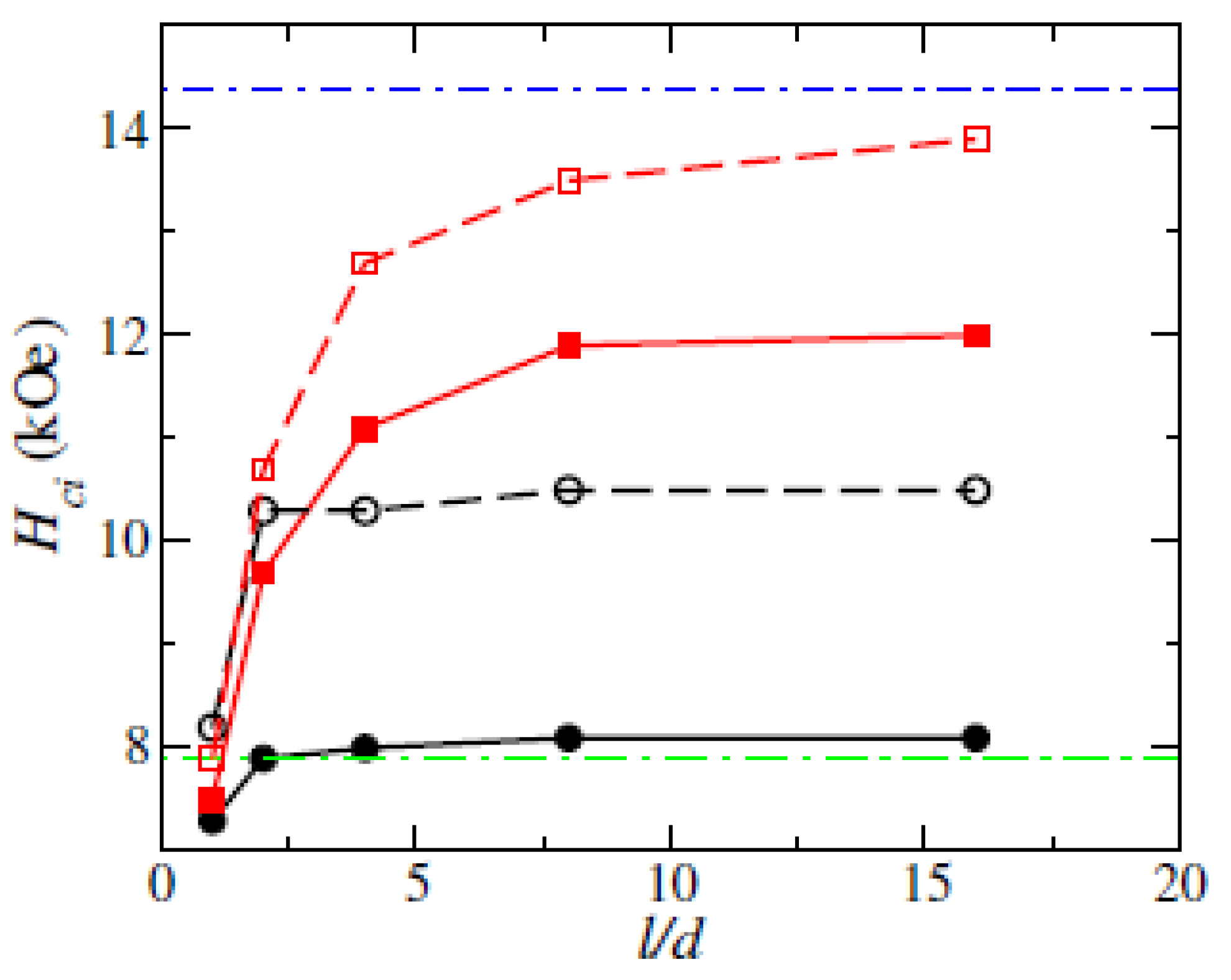
Figure 2.
The magnetization (a, c, e) and demagnetization field (b, d, f) distribution of (Fe0.7Co0.3)2B with a morphology of sphere (diameter 20 nm), s-nanowires (spheroid), and c-nanowire (cylinder) with a diameter of 16 nm and length of 256 nm at a magnetic remanent state (external field H=0), respectively. Here, the arrows are the magnetization or demagnetization directions. The easy axis of magnetization is along the z-direction (vertical direction). Only the end parts (30 nm in length) of nanowires (c, d, e ,f) are shown where the large changes in magnetization and demagnetization field.
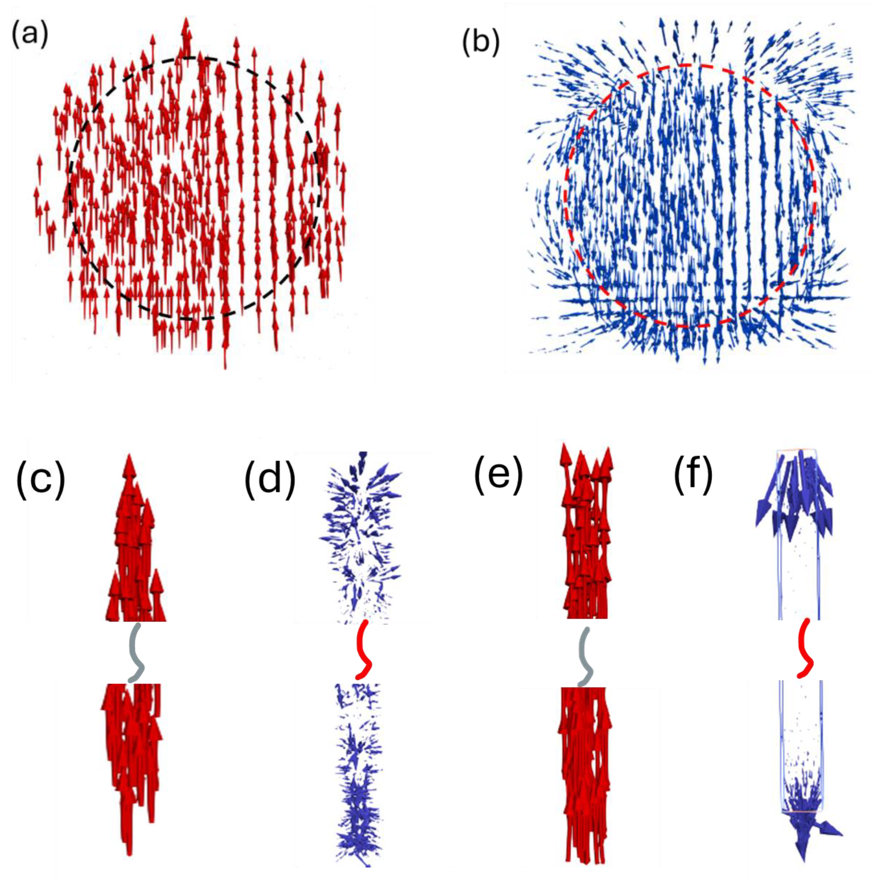
Figure 3.
Scheme of core-shell geometry models for (Fe0.7Co0.3)2B c-nanowire (a) and s-nanowire (b). The core and shell have MCA constants K1 core=4.1Merg/cm3 and K1 shell =0.7-0.9*K1 core, respectively.
Figure 3.
Scheme of core-shell geometry models for (Fe0.7Co0.3)2B c-nanowire (a) and s-nanowire (b). The core and shell have MCA constants K1 core=4.1Merg/cm3 and K1 shell =0.7-0.9*K1 core, respectively.
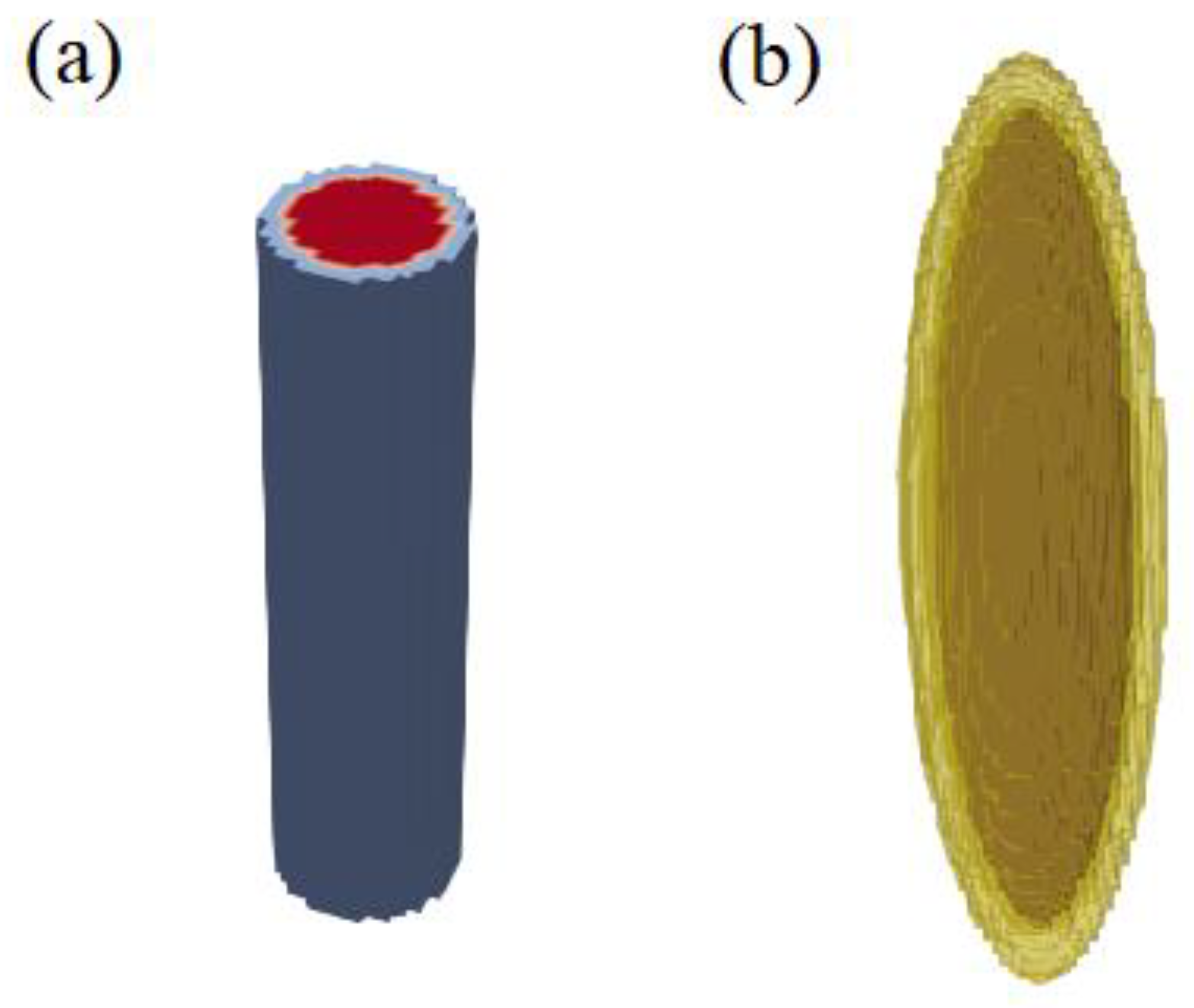
Figure 4.
The calculated coercivity as a function of MCA constants of the shell layer, K shell in (Fe0.7Co0.3)2B c-nanowire (blue solid line) and s-nanowire (red, dash line). The nanowires have diameters of 16 nm and lengths of 256 nm.
Figure 4.
The calculated coercivity as a function of MCA constants of the shell layer, K shell in (Fe0.7Co0.3)2B c-nanowire (blue solid line) and s-nanowire (red, dash line). The nanowires have diameters of 16 nm and lengths of 256 nm.
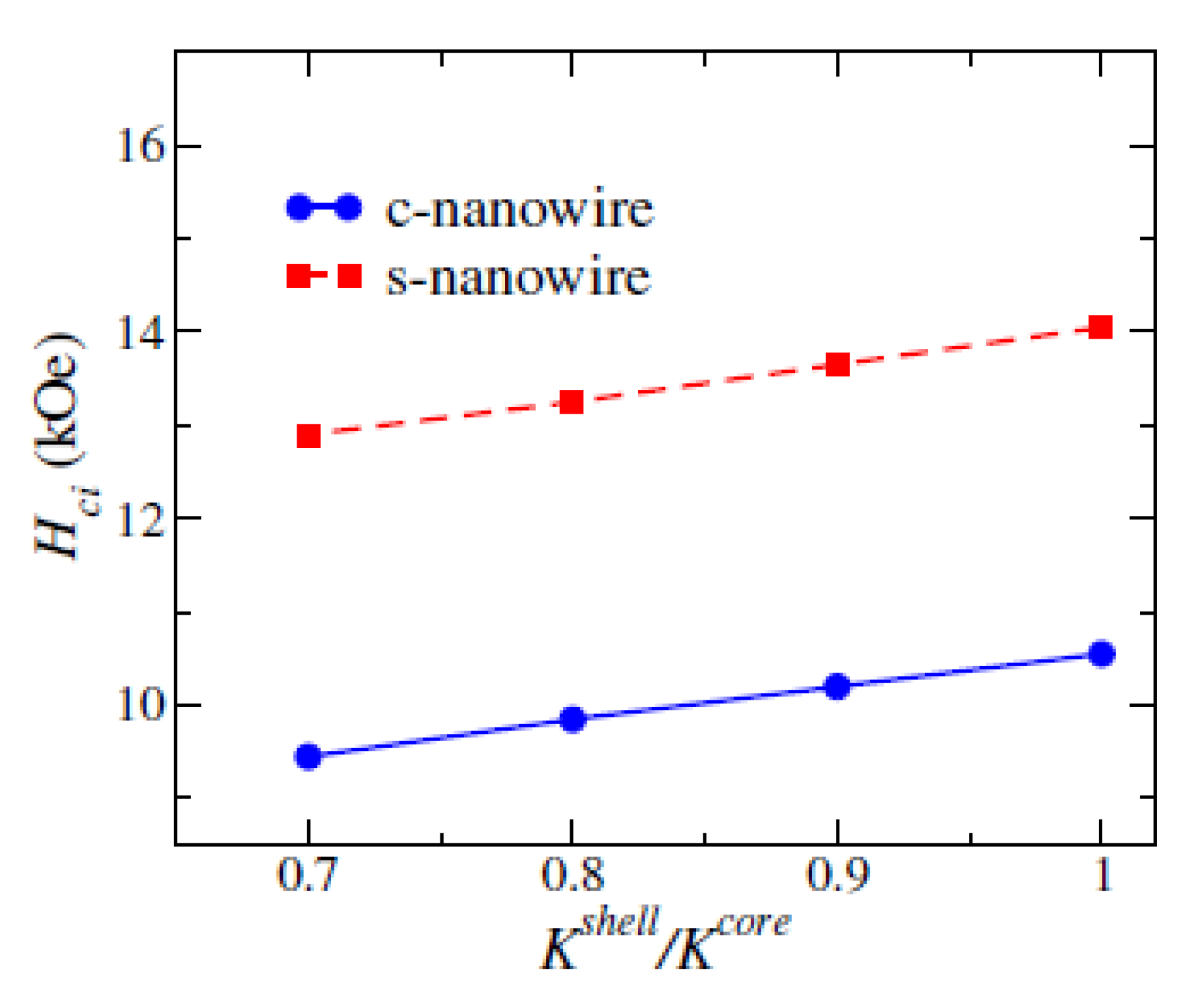
Figure 5.
Calculated coercivity Hci (a), magnetic remanence Br (b), and maximum energy product (BH)m (c) as a function of volume packing fraction of (Fe0.7Co0.3)2B nanowires in a bonded magnet. 1: s-nanowire; 2: s-nanowire with a surface defect layer of 2 nm; 3: c-nanowire; 4: c-nanowire with a surface defect layer of 2 nm.
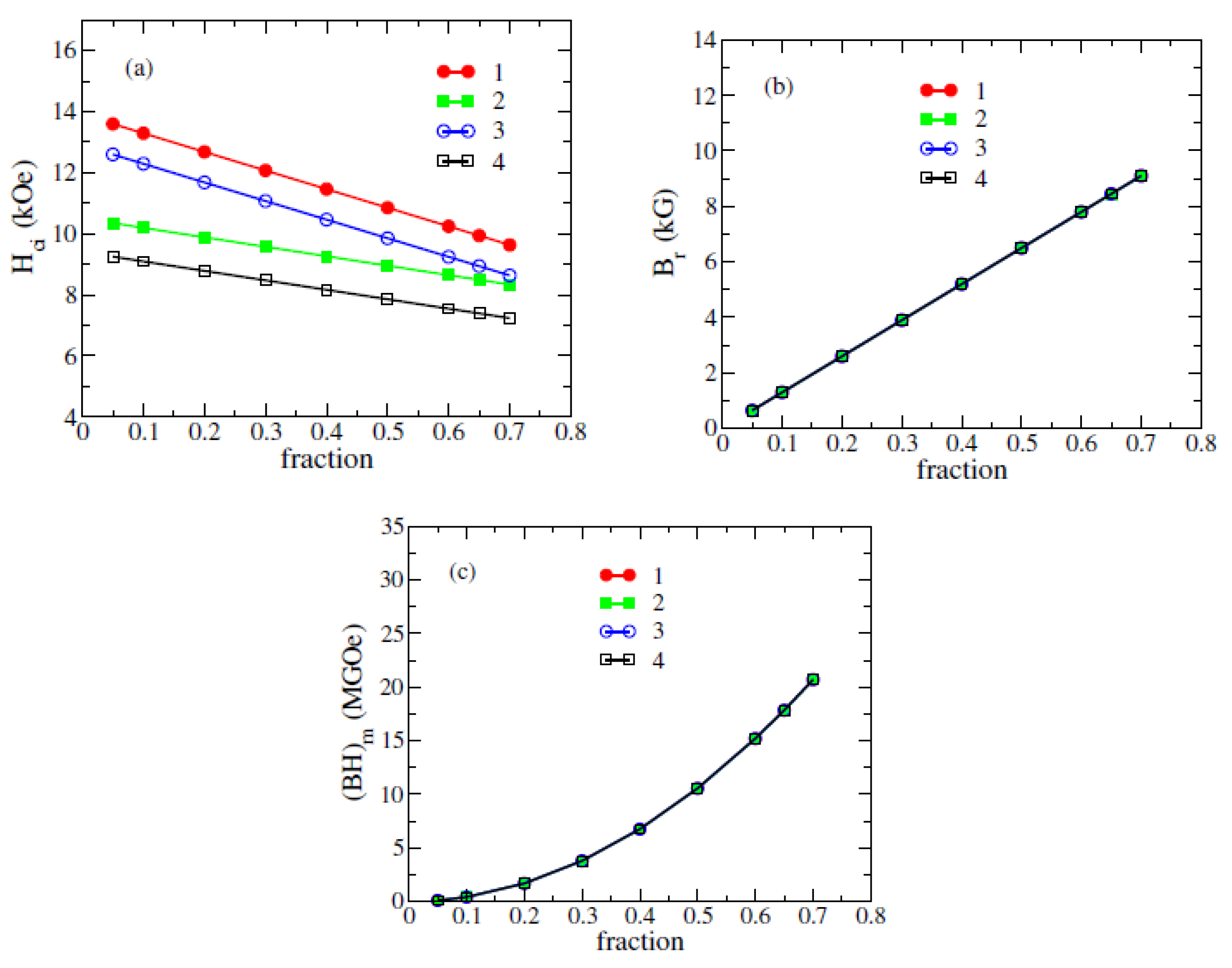
Figure 6.
Microstructure model of nanowire bonded magnet (a) and fully dense polycrystalline bulk magnet of (Fe0.7Co0.3)2B and their calculated demagnetization curves (J-H and B-H) (c) . The polycrystalline bulk magnet has a mean grain size of 20 nm and a fluctuation of MCA energy of 30% between different grains. The bonded magnet has a volume fraction of 70% for s-nanowire (Φ16×256 nm). The s-nanowire has a surface defect layer (2 nm thickness) with a reduced MCA constant K1 shell =0.7*K1 core. In Figure 6(c), the solid and dashed lines are for J-H and B-H, respectively. See more details in the main text.
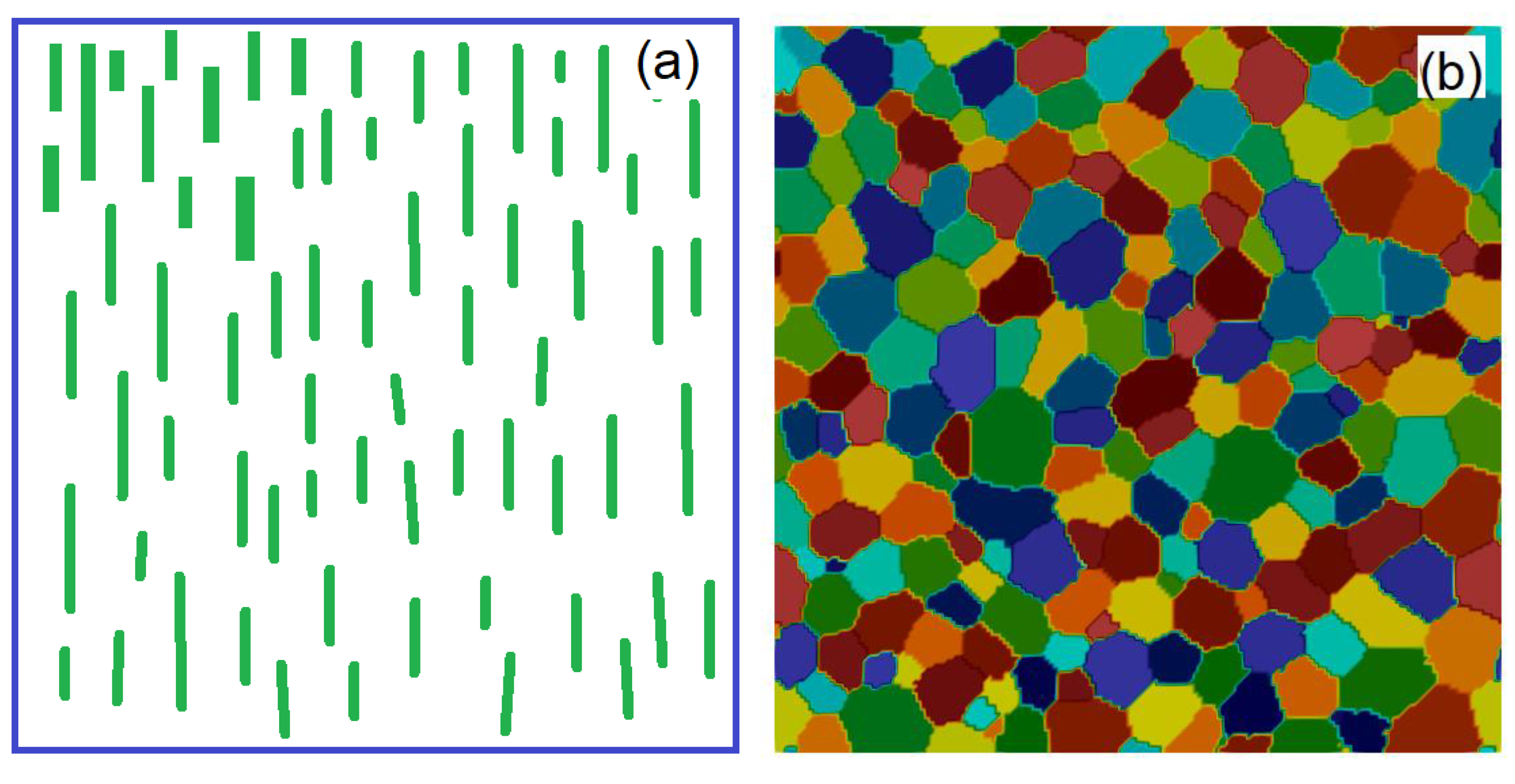
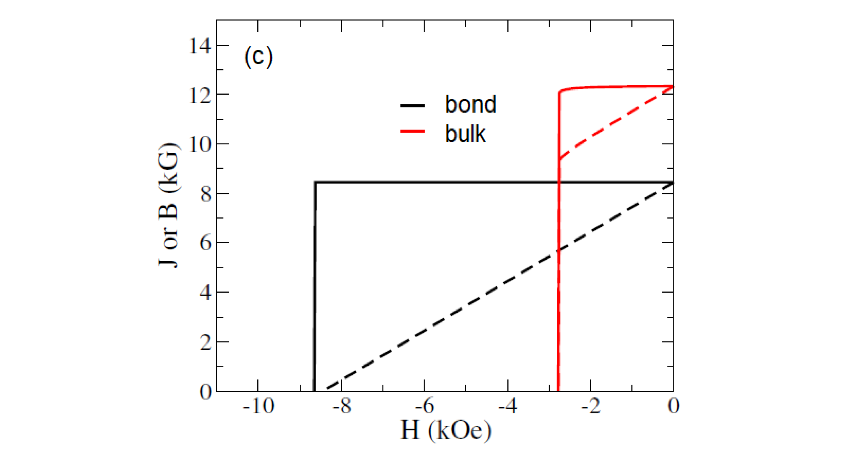

Table 1.
Magnetic properties of nanowires with different thicknesses of surface defect layer (SFL). The MCA constant of SFT, K1 shell =0.7*K1 core.
Table 1.
Magnetic properties of nanowires with different thicknesses of surface defect layer (SFL). The MCA constant of SFT, K1 shell =0.7*K1 core.
| Size (nm) | SFL Thickness (nm) | Br (kG) | Hci (kOe) | (BH)m (MGOe) | |
|---|---|---|---|---|---|
| c-nanowire | Φ16×256 | 0 | 13.0 | 10.5 | 42 |
| c-nanowire | Φ16×256 | 1 | 13.0 | 9.9 | 42 |
| c-nanowire | Φ16×256 | 2 | 13.0 | 9.4 | 42 |
| c-nanowire | Φ32×256 | 0 | 13.0 | 8.2 | 42 |
| s-nanowire | Φ16×256 | 0 | 13.0 | 14.1 | 42 |
| s-nanowire | Φ16×256 | 1 | 13.0 | 13.3 | 42 |
| s-nanowire | Φ16×256 | 2 | 13.0 | 12.9 | 42 |
| s-nanowire | Φ32×256 | 0 | 13.0 | 12.0 | 42 |
Table 2.
Estimated Parameters of A and B of (Fe0.7Co0.3)2B particle.
| nanowires | Shape | Size (nm) | A (kOe) | B (kOe) | |
| 1 | s-nanowire | Φ16×256 | 7.9 | 6.1 | |
| 2 | Core-shell s-nanowire | Core Φ 12×256 Shell thickness: 2 |
6.9 | 6.1 | K1 shell =0.7*K1 core |
| 3 | c-nanowire | Φ16×256 | 7.45 | 3.1 | |
| 4 | Core-shell c-nanowire | Core Φ 12×256 Shell thickness: 2 |
6.85 | 3.1 | K1 shell =0.7*K1 core |
Table 3.
Calculated magnetic properties of (Fe0.7Co0.3)2B and bonded magnets.
| Type | MCA Fluctuation |
Volume content | Br (kG) | Hci (kOe) | (BH)m (MGOe) |
| Bonded, c-nanowire Φ16×256 nm | 0 | 70% | 9.09 | 8.3 | 20.6 |
| Bonded, c-nanowire Φ16×256 nm | 0 | 50% | 6.5 | 8.9 | 10.5 |
| Bonded, c-nanowire Φ16×256 nm | 30% | 70% | 9.09 | 7.3 | 20.6 |
| Bonded, c-nanowire Φ16×256 nm | 30% | 50% | 6.5 | 7.9 | 10.5 |
| Bonded, s-nanowire Φ16×256 nm | 0 | 70% | 9.10 | 9.6 | 20.7 |
| Bonded, s-nanowire Φ16×256 nm | 0 | 50% | 6.5 | 10.8 | 10.5 |
| Bonded, s-nanowire Φ16×256 nm | 30% | 70% | 9.10 | 8.6 | 20.7 |
| Bonded, s-nanowire Φ16×256 nm | 30% | 50% | 6.5 | 9.8 | 10.5 |
Disclaimer/Publisher’s Note: The statements, opinions and data contained in all publications are solely those of the individual author(s) and contributor(s) and not of MDPI and/or the editor(s). MDPI and/or the editor(s) disclaim responsibility for any injury to people or property resulting from any ideas, methods, instructions or products referred to in the content. |
© 2024 by the authors. Licensee MDPI, Basel, Switzerland. This article is an open access article distributed under the terms and conditions of the Creative Commons Attribution (CC BY) license (https://creativecommons.org/licenses/by/4.0/).
Copyright: This open access article is published under a Creative Commons CC BY 4.0 license, which permit the free download, distribution, and reuse, provided that the author and preprint are cited in any reuse.


