Submitted:
10 June 2024
Posted:
11 June 2024
You are already at the latest version
Abstract
This letter presents a dual-frequency terahertz amplitude modulator based on a cross-shaped structure and U-shaped metal patches. Its structural unit is a typical metal-substrate structure. The top metal consists of a cross-shaped structure and U-shaped metal patches, and the bottom substrate layer is made of quartz. Amplitude modulation is achieved by adjusting the temperature of the vanadium dioxide (VO2) patches. The modulation depth can be approximately 75%. The mechanism of the resonance frequency is explained by the equivalent circuit model. The proposed structure shows good amplitude modulation capability at different incidence and azimuth angles by changing the location of the VO2 patches. The dual-frequency terahertz amplitude modulator can be used in terahertz communication, imaging, etc.
Keywords:
terahertz waves
; metamaterial
; amplitude modulator
1. Introduction
Terahertz waves are electromagnetic waves with frequencies from 0.1 to 10 THz [1]. The high-frequency portion of terahertz waves overlaps with infrared waves, while the low-frequency portion overlaps with millimeter waves. Terahertz waves offer several advantages, such as low photon energy [2], which ensures high safety in imaging compared to X-rays. Their high penetration ability [3] enables the non-destructive detection of material structures. Terahertz waves have diverse spectral properties and are applicable in materials characterization and terahertz communication, making communication one of the critical applications of this technology.
A standard terahertz communication system [4] includes various components, including a terahertz radiation source [5] that uses a photoconductive antenna or electronic generation, a terahertz modulator [6], a terahertz mixer [7], a terahertz power divider [8], and a terahertz coupler [9]. Terahertz communication systems utilize various functional devices, with the terahertz modulator playing a crucial role in the system by significantly affecting its overall performance. The specifications of a terahertz modulator typically include parameters such as terahertz modulation depth [10], modulation rate [11] and dynamic modulation characteristics [12].
A temperature-controlled terahertz modulator modulates incident terahertz waves by changing the temperature, which changes the conductivity or dielectric constant of the controllable semiconductor, resulting in a change in the resonant frequency or intensity of the metamaterial structure. In 2009, T. Driscoll et al. [13] designed a terahertz modulator using VO2 patches and a metamaterial structure to change the resonant frequency for modulation. In 2011, R. Singh et al. [14] developed a terahertz modulator using strontium titanate, which showed a frequency redshift of 43% when the temperature changed from 409 K to 150 K. In the same year, J. Zhu et al. [15] integrated indium antimonide materials into the metamaterial SRR structure, which opened to modulate terahertz wave frequencies. Li Chun's team also achieved a modulation range of 65% by incorporating indium antimonide material into the SRR structure opening of the metamaterial with a temperature variation of 160 K to 350 K. In 2021, C. Li et al. [16] developed an electrically controlled superconducting terahertz modulator using niobium nitride materials and achieved a modulation depth of 82.7% at 0.33 THz. While research on temperature-controlled terahertz modulators has progressed, challenges remain in their practical application. Developing innovative structures for these modulators can increase progress in their implementation.
The study initially focuses on the design of a dual-frequency terahertz amplitude modulator using a cross-shaped structure and U-shaped metal patches based on VO2 patches. Then, the resonance frequency of the amplitude modulator is analyzed with VO2 patches. Then, the amplitude modulation mechanism is explained by an equivalent circuit model. In addition, the influence of different structural parameters on the resonant characteristics of the modulator in the On-Off state is also studied. The proposed dual-frequency terahertz amplitude modulator is helpful for the field of terahertz communication, imaging, etc.
2. Structure Design and Mechanism
The objective of our study is to design a dual-frequency terahertz amplitude modulator based on a cross-shaped structure and U-shaped metal patches. This coupling effect between structures is enhanced by the integration of vanadium dioxide patches between the U-shaped metal patches and the cross-shaped structure. Temperature variations are used to adjust the coupling between these two structures. The study also examines the dimensions of the U-shaped structure and the distance from the cross-shaped structure to analyze the resonance frequency of the dual-frequency terahertz amplitude modulator. The resonance frequency generation is examined using an equivalent circuit model. In addition, the study investigates the stability at different incidence and azimuth angles for the cross-shaped structure and U-shaped metal patches.
2.1. Design of Terahertz Dynamic Modulator
In this letter, the designed dual-frequency terahertz amplitude modulator is made of metal-dielectric which is a two-layer structure. The metal is made of aluminum and its conductivity is 3.56✕107 S/m. The dielectric layer is quartz, the real part of its dielectric constant is 3.75, and the tangent of the loss angle is 0.0004. The device performance simulation is carried out in CST Microwave Studio 2018, using a frequency domain solver with periodic boundary conditions in the x and y directions and open boundary conditions in the z-direction.
Figure 1 shows a schematic diagram of a periodic unit for a dual-frequency terahertz amplitude modulator that uses a cross-shaped structure and U-shaped metal patches. The upper diagram in Figure 1 shows the smallest structural units and the lower diagram schematically shows the periodic structural units. The combined structure consists of two parts, the upper layer is made of a cross-shaped structure and U-shaped metal patches and the lower layer is made of quartz. The cross-shaped structure and the U-shaped metal patches are connected using VO2 patches. The length and width of the cross-shaped structure are L=100 μm and w1=5 μm, respectively. The depth of the U-shaped metal patches is w2=10 μm, and the distance between the U-shaped metal patches and the cross-shapedstructure in the vertical direction is a=4 μm. The distance between the U-shaped metal patches and the cross-structure in the horizontal direction is d=25 μm. The values of Px and Py are 150 μm. The thickness of the quartz substrate is t=25 μm. Four VO2 patches are positioned between the cross and U-shaped metal structures. By adjusting the temperature, the conductivity of VO2 patches can be changed, facilitating connection and separation between the cross-shaped structure. This setting can influence the coupling effect between the cross-shaped structure and the U-shaped metal patches.
We simulated the effect of VO2 patches on the transmission coefficient of the structure under various conductivity states. We analyzed the current distribution of the structure under high (On) and low (Off) conductivity states respectively. Fig.2 shows the variation of the transmission coefficient of the structure as the conductivity of VO2 patches changes. The current states, on and off, are depicted on the right side of Figure 2. At high conductivity (g=4✕107 S/m), the switch is on, and the current loop related to low resonance frequency (On state) is depicted as j. Conversely, at low conductivity (g=2 S/m), the switch is open, and the current loop related to high resonance frequency (Off state) is displayed as k in Figure 2. The intensity of the high-frequency resonance decreases gradually as the conductivity rises. In contrast, the intensity of the low-frequency resonance increases as the conductivity rises. It is observed that the current loop at low-frequency resonance at the on state is longer than that at high-frequency resonance at the off state. According to equivalent circuit theory, the equivalent inductance is governed by the equation , where l represents the current loop length. The resonant frequency follows the relationship: , L and C represent the circuit's equivalent inductance and capacitance. Due to the longer length of the current loop associated with resonance frequency, the resonance frequency of the amplitude modulator in the off state is higher than the resonance frequency in the on state.
To further investigate the formation mechanism of the high-frequency resonance peak fj, we analyze the transmission coefficients of the cross-shaped structure and the U-shaped metal spots separately. We also examine the combined structure without the VO2 patches, as shown in Figure 3. The black solid line in Figure 3 represents the transmission coefficients of the combined structure. In contrast, the red dashed line represents of the cross-shaped structure and the blue dashed line highlights the U-shaped metal patches. In resonance mode, a light-dark coupling effect is observed at high-frequency resonance. The incident electromagnetic wave with y-polarization does not directly stimulate the two U-shaped metal patches with openings up and down. Instead, the resonant field energy is coupled through the vertical structure of the cross-shaped structure, as illustrated in fj in Figure 3. As the resonance frequency increases, the coupling effect becomes more pronounced. At the transparent window, the resonant frequency fk is reached, and the overall resonant field of the structure decreases. The bright mode (cross structure) generates a dark mode (U-shaped structure with an opening downwards) while simultaneously suppressing each other, thereby reducing the total resonant field and weakening the structure's ability to localize the incident electromagnetic wave, increasing in the transmission coefficient. At the resonance frequency of fl, the electromagnetic wave directly induces the resonance effect within the two U-shaped metal patches with horizontal openings, creating a new resonance field.
2.2. Equivalent Circuit Modelling in the On and Off States
The equivalent circuit of the terahertz dual-frequency terahertz amplitude modulator is shown in Figure 4, where the incident wave is vertically polarized. The VO2 patches act as a temperature control switch, connecting the cross-shaped structure in the middle to the U-shaped metal patches. When the switch is conducting (on), the oscillating circuit path is red. When the switch is closed (off), the oscillating circuit path is blue. The resonance intensity of the two circles correlates with the transmission coefficients of the respective peaks. As the switch is gradually turned on, the resonance intensity of the low-frequency resonance increases, while the high-frequency resonance loop is increasingly disturbed, resulting in a decrease in its resonance intensity. Thus, the dual-channel modulation effect is achieved by modulating the temperature with the baseband signal. Based on the formula , M is the modulation depth and V represents the amplitude of the modulated envelope signal. The modulation depth is 75.4% for the low-frequency component and 73.5% for the high-frequency component.
2.3. Transmission Coefficients for Different Coupling Effects
To investigate the coupling effect between the structures, transmission coefficients were explored at varying distances d from 15 to 30 µm, as depicted in Figure 5. To improve clarity regarding the location of resonance peaks in transmission coefficients, two vertical dashed lines are utilized to mark the low and high-frequency peaks. The coupling effect between the U-shaped metal patch and the cross-shaped structure is manifested in the intensity and bandwidth of the electromagnetically induced transparent peaks. An increase in the parameter d results in a rise in the intensity and bandwidth of the transparent resonance peaks, indicating a strengthened coupling between the structures. At g=1.2✕107 s/m, the frequency of the low-frequency resonance peak remains nearly constant, but the intensity slightly decreases. However, when g=40 s/m, the intensity of frequency fI =0.46 THz in the transmission coefficients remains relatively constant with increasing d values. Regarding high-frequency resonance peaks, the frequency of fII=0.85 THz is blue-shifted with increasing d values at g=40 s/m. Conversely, at g=1.2✕107 s/m, the high-frequency resonance frequency experiences a blueshift as d increases. Notably, at d=25 µm, the terahertz modulation effect is relatively effective, leading to dual-state switching at fII. This finding suggests that achieving a terahertz modulation effect with dual frequencies at d=25 µm is feasible by controlling the temperature of VO2 patches.
We conduct a detailed analysis of the factors influencing resonance frequencies at various distances. The resonance frequencies are associated with two terahertz communication bands, specifically 0.46 THz and 0.85 THz. Increasing the parameter d shortens the current loop of the U-shaped structure, causing the resonance peak to shift to a higher frequency (blue dashed line in Figure 3). The position of the resonance peak generated by the excitation of the cross-shaped structure remains stable, resulting in a larger frequency separation between the two resonance peaks. Furthermore, the higher value of d increases the physical separation between the cross-shaped and U-shaped metal patches, resulting in a reduction in the coupling effect. The high-frequency modulation peak increasingly approaches the resonance frequency induced by the cross-shaped structure (red dashed line in Figure 3), with the transition from the black solid line to the red dashed line in Figure 3. So, the frequency, bandwidth and resonance intensity increase, as indicated by the green solid line in Figure 5.
As shown in Figure 6, the transmission coefficients for different values of w2 are shown. The VO2 patches in Figure 6 have a conductivity of 40 S/m in the solid line and a conductivity of 1.2✕107 S/m in the dashed line. When g = 40 S/m, the frequency and intensity of the low-frequency resonance in the transmission coefficients remain essentially constant as w2 increases. Figure 6 shows that the high-frequency resonance gradually shifts to higher frequencies as the internal depth w2 of the U-shaped metal patch increases. This is mainly because as the depth w2 of the U-shaped metal patches increases, the effective length of the current flowing through the cross-shaped structure and the U-shaped metal patches gradually decreases as the U-shaped metal patches and the cross-shaped structure are connected. The equivalent inductance connecting the U-shaped structure and the cross-shaped structure decreases and the frequency of the high-frequency resonance peak tends to shift at high frequencies. In contrast, the equivalent capacitance remains approximately the same.
2.4. Incidence Angle and Polarization Properties of Combined Structures
The transmission coefficients at different angles of incidence of terahertz waves for conductivities g=40 S/m and g=1.2✕107 S/m are shown in Figure 7. The angles of incidence of the terahertz waves range from 0° to 75°. At a conductivity of g=1.2✕107 S/m, the low-frequency resonance remains stable as the angle of incidence of the terahertz waves increases. In contrast, the intensity of the low-frequency resonance gradually decreases. In addition, the high-frequency resonance exhibits a red shift with increasing angle of incidence of the terahertz waves. The dual-frequency terahertz amplitude modulator demonstrated angular stability from 0o to 30o.
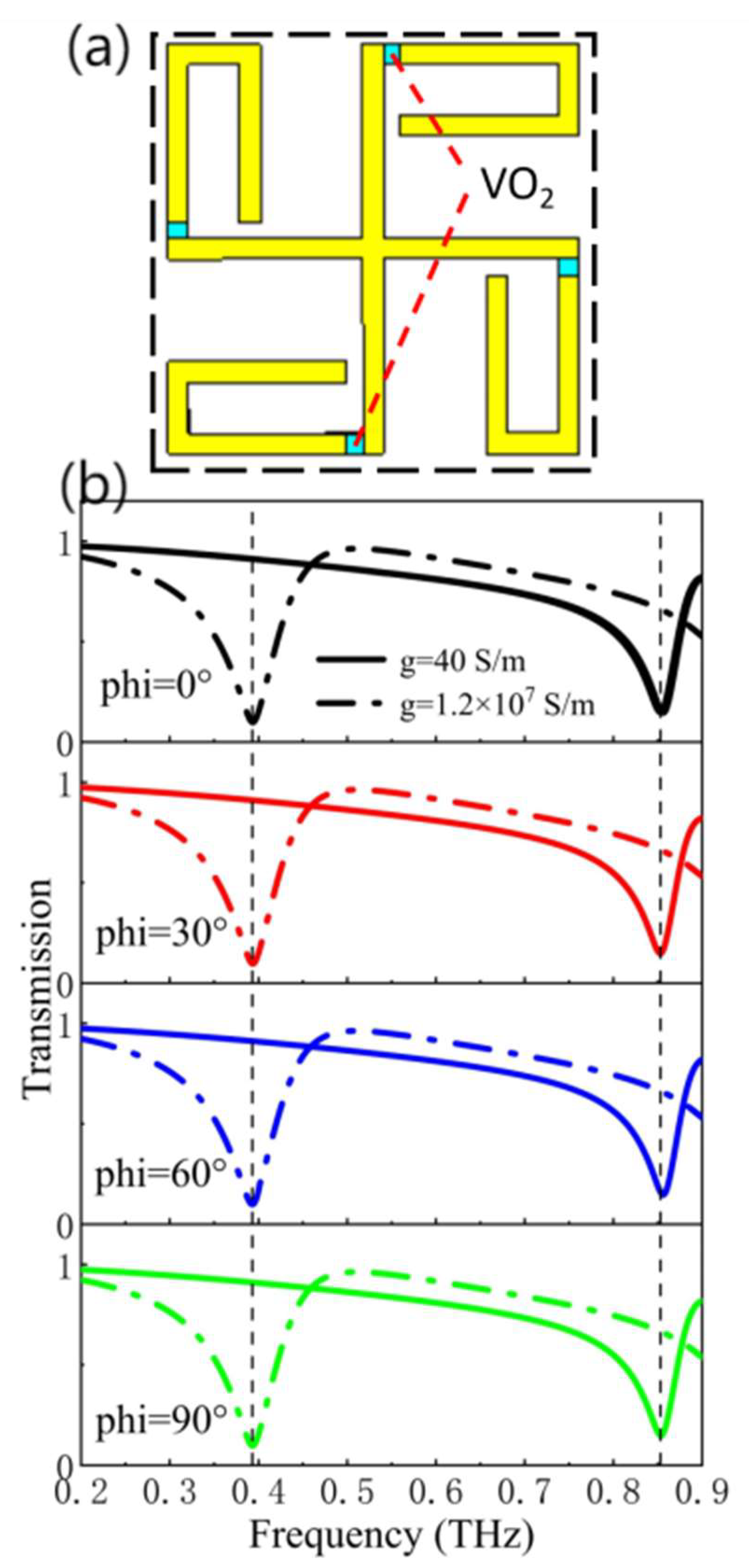
To investigate the polarization-insensitive properties of the structure, four VO2 patches were inserted on the outside between the U-shaped metal patches and the cross-shaped structures. Figure 8(a) shows the schematic of the symmetrical structure. Figure 8(b) shows the transmission coefficients of VO2 patches in both on and off states at different azimuth angles. The azimuth angle of terahertz waves is between 0° and 90°. In Figure 8(b), the transmission coefficients remain constant when the azimuth angles vary between 0° and 90°, regardless of whether the VO2 patches are turned on or off. This observation suggests that the structure exhibits polarization insensitivity.
3. Conclusion
This letter proposes a terahertz dual-frequency amplitude modulator achieved by coupling a cross structure with U-shaped metal patches. We examined the modulation depth of the dual-frequency modulator by varying the temperature to modulate the conductivity of the VO2 patches, the size of the U-shaped metal patches, and the distance between the cross-shaped structure. An equivalent circuit model is used to investigate the physical mechanisms underlying the formation of resonance frequencies at lower and higher frequencies. The modulation depth of the dual-frequency terahertz amplitude modulator can reach about 75%. By symmetrically positioning the VO2 patches, we examined the incidence angles and polarization insensitivity properties with both the U-shaped metal patches and the cross-shaped combination structure. The results show that the dual-frequency terahertz amplitude modulator has good angle of incidence and polarization insensitivity (by changing the location of the VO2 patches) characteristics. In summary, the proposed dual-frequency terahertz amplitude modulator is useful for applications in terahertz communication, imaging, etc.
Conflict of Interest:
The authors have no conflicts to disclose.
DATA AVAILABILITY:
The data that support the findings of this study are available from the corresponding author upon reasonable request.
Author Contributions
Linji Yang: Data curation (lead); Formal analysis (lead); Software (equal); Writing-original draft (equal). Huan Zhou: Formal analysis (equal); Methodology (equal); software (lead); Kuan Ye: data curation (equal); Formal analysis (equal). Xin Chen: Formal analysis (equal); Methodology (equal); software(lead); co-supervision; Zhen Zhang: Conceptualization (lead); Funding acquisition(lead); Supervision(lead); Writing-review and editing (equal); Yong Ma: Conceptualization(lead); Funding acquisition(lead); Supervision(lead); Writing-review and editing (equal); Renpu Li: Conceptualization(lead); Funding acquisition(lead); Supervision(lead); Writing-review and editing (equal).
Funding
This project was funded by National Natural Science Foundation of China (No. 62375031), Chongqing Postdoctoral Science Foundation (No. cstc2021jcyj-bsh0194), Scientific and Technological Research Program of Chongqing Municipal Education Commission (Grant No. KJQN202200602), the Chongqing University of Posts and Telecommunications (Grant Nos. A2018-01, A2020-250, A2020-557, 2023-251), and College Students' Innovation and Entrepreneurship Training Program of CQUPT (Grant Nos. X20221061711025 and X20231061710).
References
- Kleine-Ostmann, T.; Nagatsuma, T. A Review on Terahertz Communications Research. J. Infrared, Millimeter, Terahertz Waves 2011, 32, 143–171. [Google Scholar] [CrossRef]
- Gao, Y.; Kaushik, S.; Philip, E.J.; Li, Z.; Qin, Y.; Liu, Y.P.; Zhang, W.L.; Su, Y.L.; Chen, X.; Weng, H.; et al. Chiral terahertz wave emission from the Weyl semimetal TaAs. Nat. Commun. 2020, 11, 1–10. [Google Scholar] [CrossRef] [PubMed]
- Valušis, G.; Lisauskas, A.; Yuan, H.; Knap, W.; Roskos, H.G. Roadmap of Terahertz Imaging 2021. Sensors 2021, 21, 4092. [Google Scholar] [CrossRef] [PubMed]
- Song, H.-J.; Lee, N. Terahertz Communications: Challenges in the Next Decade. IEEE Trans. Terahertz Sci. Technol. 2022, 12, 105–117. [Google Scholar] [CrossRef]
- Davies, A.G.; Linfield, E.H.; Johnston, M.B. The development of terahertz sources and their applications. Phys. Med. Biol. 2002, 47, 3679–3689. [Google Scholar] [CrossRef] [PubMed]
- Rahm, M.; Li, J.-S.; Padilla, W.J. THz Wave Modulators: A Brief Review on Different Modulation Techniques. J. Infrared, Millimeter, Terahertz Waves 2012, 34, 1–27. [Google Scholar] [CrossRef]
- Federici, J.; Moeller, L. Review of terahertz and subterahertz wireless communications. J. Appl. Phys. 2010, 107, 111101. [Google Scholar] [CrossRef]
- Reichel, K.S.; Mendis, R.; Mittleman, D.M. A Broadband Terahertz Waveguide T-Junction Variable Power Splitter. Sci. Rep. 2016, 6, 28925. [Google Scholar] [CrossRef] [PubMed]
- Niu, Z.; Zhang, B.; Ji, D.; Yang, Y.; Liu, Y.; Feng, Y.; Fan, Y.; Chen, Z.; Chen, X.; Li, D. A Novel 3-dB Waveguide Hybrid Coupler for Terahertz Operation. IEEE Microw. Wirel. Components Lett. 2019, 29, 273–275. [Google Scholar] [CrossRef]
- Liang, G.; Hu, X.; Yu, X.; Shen, Y.; Li, L.H.; Davies, A.G.; Linfield, E.H.; Liang, H.K.; Zhang, Y.; Yu, S.F.; et al. Integrated Terahertz Graphene Modulator with 100% Modulation Depth. ACS Photon- 2015, 2, 1559–1566. [Google Scholar] [CrossRef]
- Zhang, Y.; Qiao, S.; Liang, S.; Wu, Z.; Yang, Z.; Feng, Z.; Sun, H.; Zhou, Y.; Sun, L.; Chen, Z.; et al. Gbps Terahertz External Modulator Based on a Composite Metamaterial with a Double-Channel Heterostructure. Nano Lett. 2015, 15, 3501–3506. [Google Scholar] [CrossRef] [PubMed]
- Li, C.; Wu, J.; Jiang, S.; Su, R.; Zhang, C.; Jiang, C.; Zhou, G.; Jin, B.; Kang, L.; Xu, W.; et al. Electrical dynamic modulation of THz radiation based on superconducting metamaterials. Appl. Phys. Lett. 2017, 111, 092601. [Google Scholar] [CrossRef]
- T. Driscoll, et al. Memory metamaterials[J]. Science 325(5947): 1518-1521(2009). DOI: 10.1126/science.11765.
- Singh, R.; Azad, A.K.; Jia, Q.X.; Taylor, A.J.; Chen, H.-T. Thermal tunability in terahertz metamaterials fabricated on strontium titanate single-crystal substrates. Opt. Lett. 2011, 36, 1230–1232. [Google Scholar] [CrossRef] [PubMed]
- Zhu, J.; Han, J.; Tian, Z.; Gu, J.; Chen, Z.; Zhang, W. Thermal broadband tunable Terahertz metamaterials. Opt. Commun. 2011, 284, 3129–3133. [Google Scholar] [CrossRef]
- Li, C.; Jiang, L.; Ma, Q.; Teng, Y.; Bian, B.; Yu, M.; Hua, M.; Liu, X.; He, J.; Su, R.; et al. Electrically tunable terahertz switch based on superconducting subwavelength hole arrays. Appl. Opt. 2021, 60, 7530–7535. [Google Scholar] [CrossRef] [PubMed]
Figure 1.
A schematic diagram of a periodic cell structure of the dual-frequency terahertz amplitude modulator based on cross-shaped and U-shaped metal patches.
Figure 1.
A schematic diagram of a periodic cell structure of the dual-frequency terahertz amplitude modulator based on cross-shaped and U-shaped metal patches.
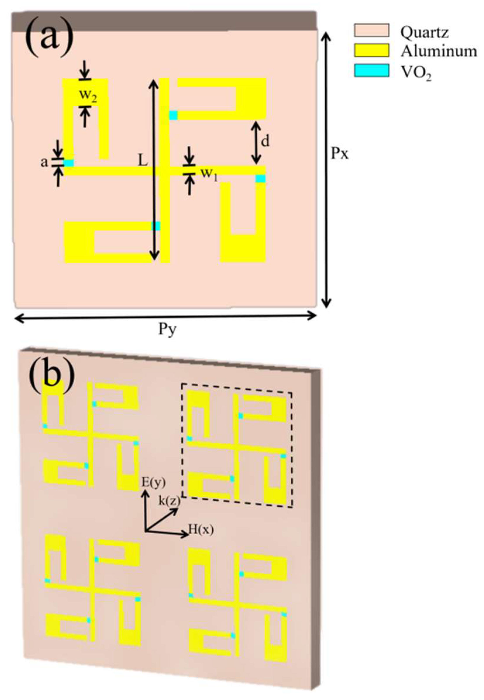
Figure 2.
Transmission coefficients of the dual-frequency terahertz amplitude modulator at different conductivities. j and k indicate the current distribution in the on and off states.
Figure 2.
Transmission coefficients of the dual-frequency terahertz amplitude modulator at different conductivities. j and k indicate the current distribution in the on and off states.
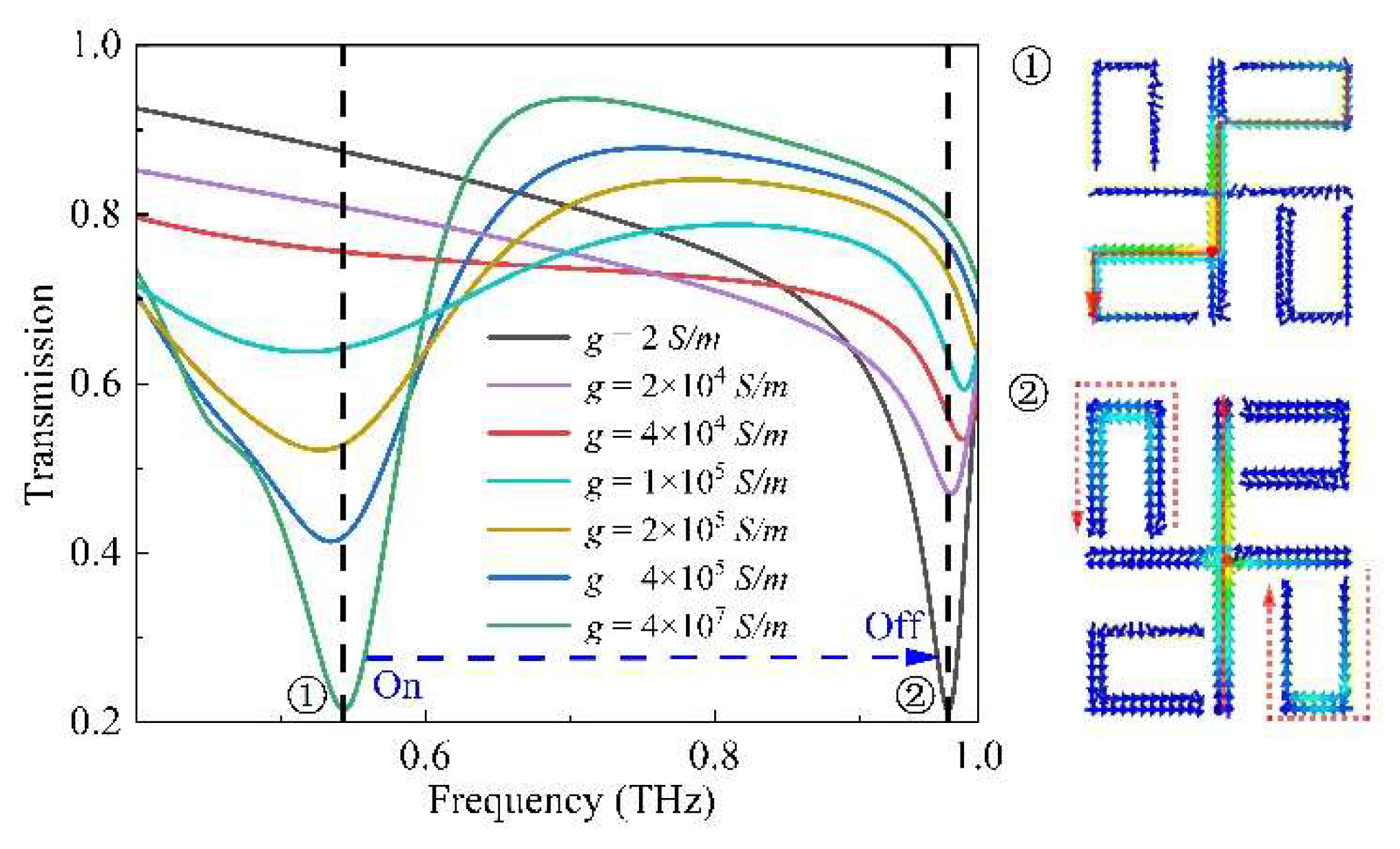
Figure 3.
Transmission coefficients and current distributions for the combined structure, cross-shaped structure and four U-shaped metal patches.
Figure 3.
Transmission coefficients and current distributions for the combined structure, cross-shaped structure and four U-shaped metal patches.
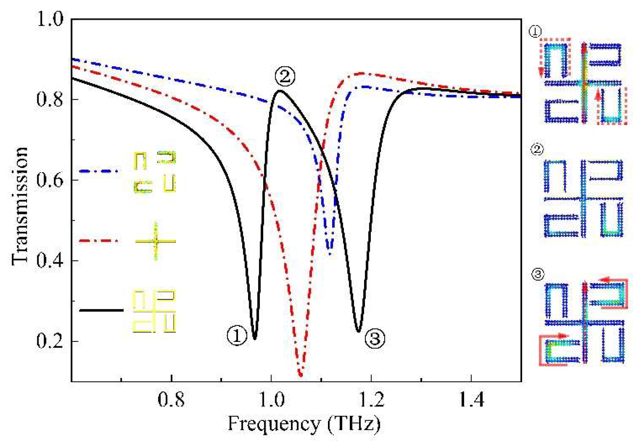
Figure 4.
Equivalent circuit model of the dual-frequency terahertz amplitude modulator when VO2 patches are in the on and off states.
Figure 4.
Equivalent circuit model of the dual-frequency terahertz amplitude modulator when VO2 patches are in the on and off states.
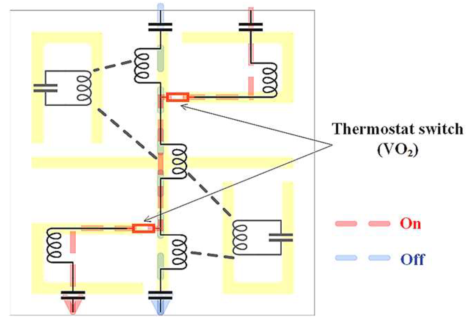
Figure 5.
Transmission coefficients at different distances d.
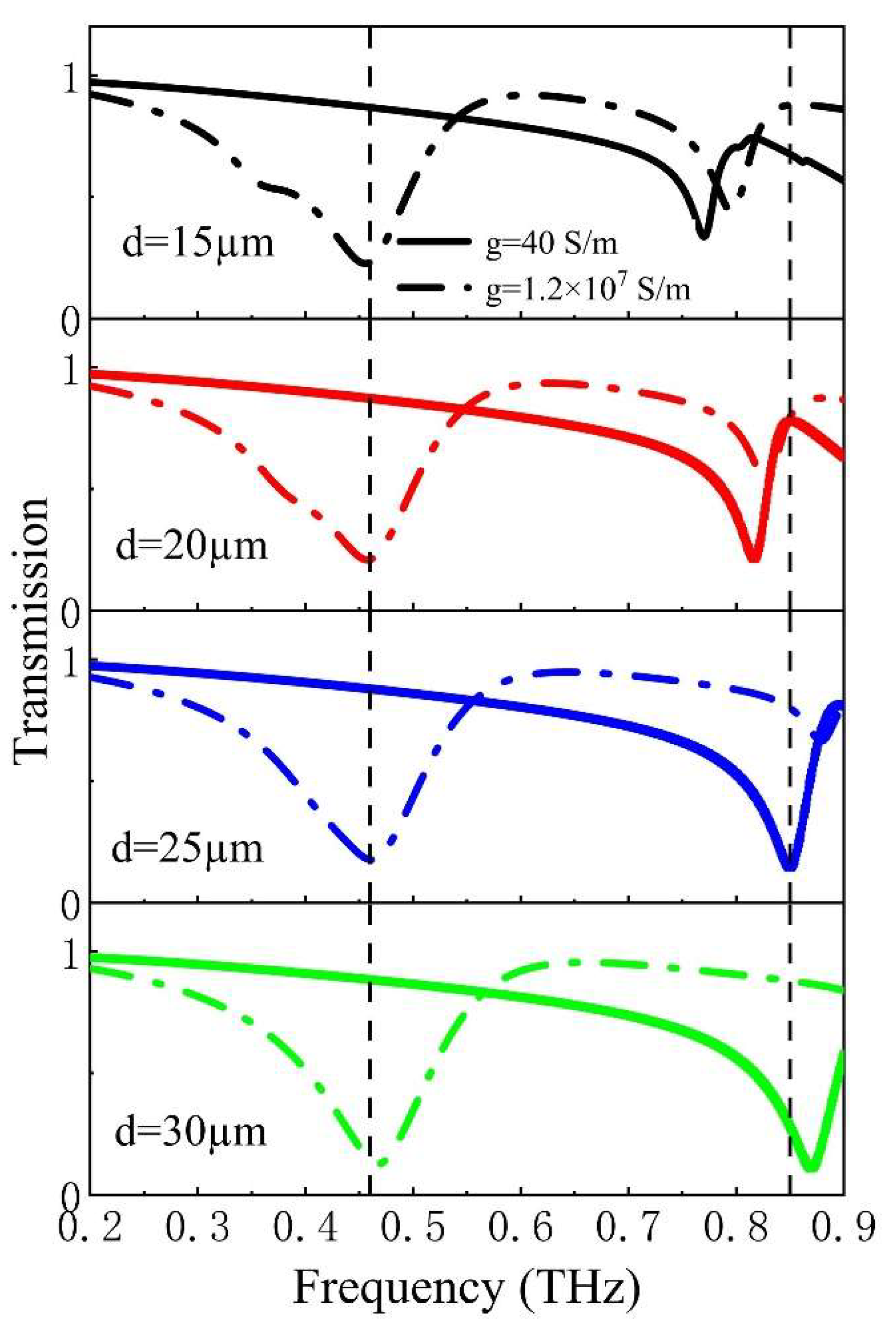
Figure 6.
Transmission coefficients for different w2. The conductivity of VO2 patches in the solid line is 40 S/m and the conductivity of VO2 patches in the dashed line is 1.2✕107 S/m.
Figure 6.
Transmission coefficients for different w2. The conductivity of VO2 patches in the solid line is 40 S/m and the conductivity of VO2 patches in the dashed line is 1.2✕107 S/m.
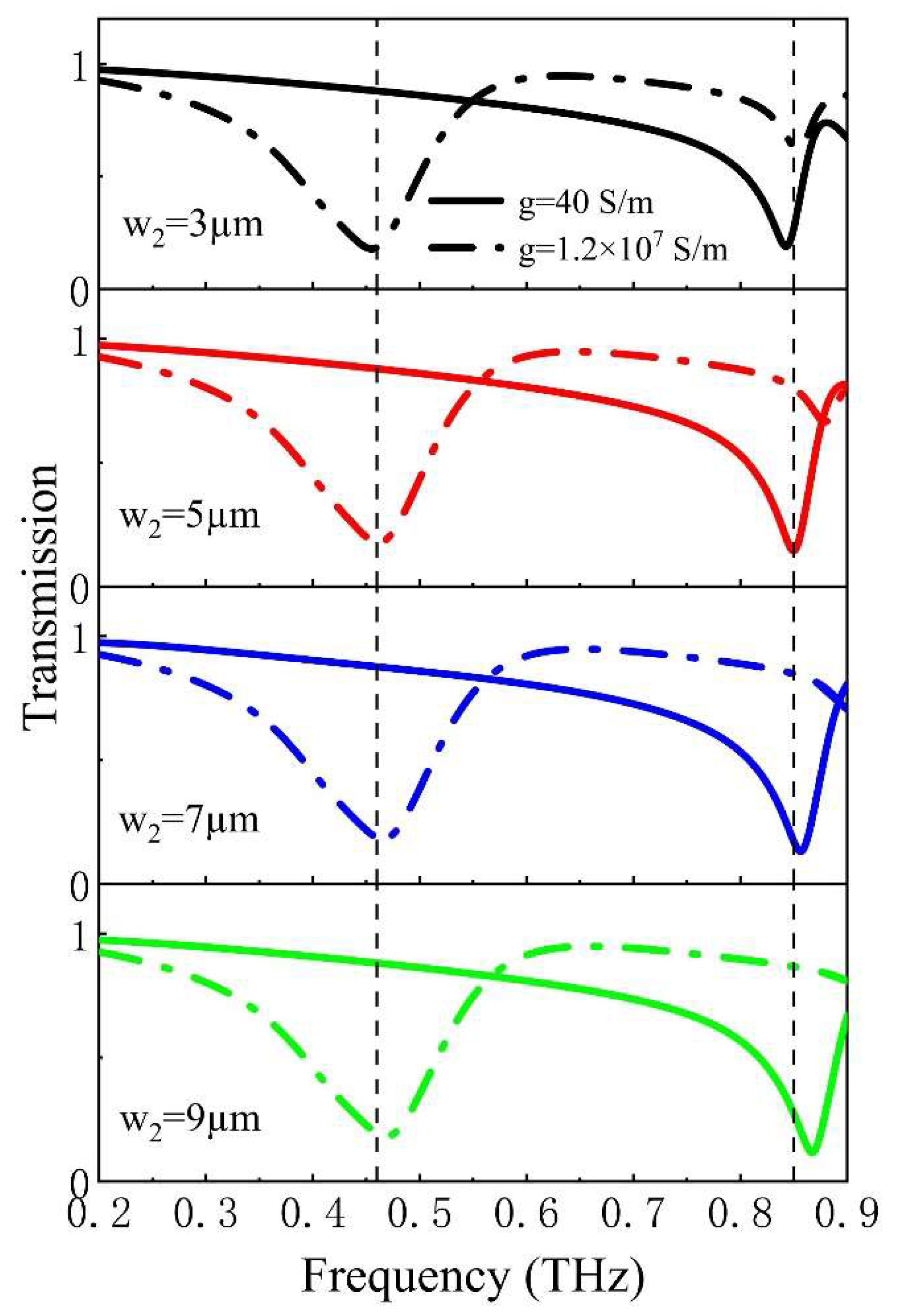
Figure 7.
Transmission coefficients of the structure with VO2 in the on or off states at different incidence angles.
Figure 7.
Transmission coefficients of the structure with VO2 in the on or off states at different incidence angles.
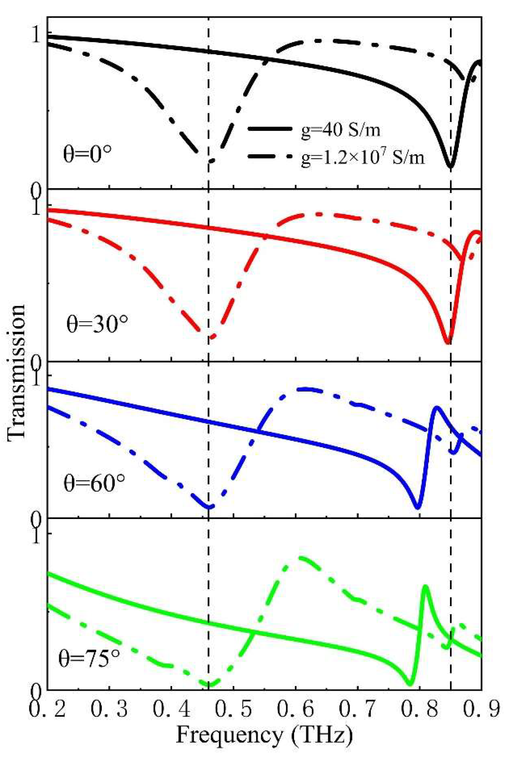
Figure 8.
Terahertz polarization properties based on symmetric structures.
Disclaimer/Publisher’s Note: The statements, opinions and data contained in all publications are solely those of the individual author(s) and contributor(s) and not of MDPI and/or the editor(s). MDPI and/or the editor(s) disclaim responsibility for any injury to people or property resulting from any ideas, methods, instructions or products referred to in the content. |
© 2024 by the authors. Licensee MDPI, Basel, Switzerland. This article is an open access article distributed under the terms and conditions of the Creative Commons Attribution (CC BY) license (http://creativecommons.org/licenses/by/4.0/).
Copyright: This open access article is published under a Creative Commons CC BY 4.0 license, which permit the free download, distribution, and reuse, provided that the author and preprint are cited in any reuse.


