Submitted:
07 June 2024
Posted:
11 June 2024
You are already at the latest version
Abstract
The number of physical devices connected to the Internet such as vehicles, household appliances and other "things" has been steadily increasing in recent years, thus forming the basis for the Internet of Things (IoT). IoT ecosystem extends beyond country borders and application domains, combining thousands of versatile devices that differ in terms of their structures, capabilities, and available resources. It is therefore not surprising that the landscape of wireless communication technologies and the degree of IoT devices available today is excessively broad and diverse. Interference between networks leads to frame collisions and consequent packet loss. Frame collisions occur when two or more packets overlap in time and frequency and use the same LoRa parameters, i.e. the same spreading factor (SF), bandwidth (BW) and carrier frequency (CF). When most devices use the same configuration, collision probability is higher. The probability of frame collisions is also affected by traffic characteristics, particularly the periodicity of the transmission and the payload size. Larger payload sizes and more frequent transmissions accumulate with higher time on air (ToA) and channel occupancy [1]. Transmission powers and the location of the gateways also influences this situation. The aim of this experimental work is to verify the effects of collisions and interference in LoRaWAN, regarding the periodicity of transmissions and the payload sizes. The hardware used is an Arduino board programmed in C/C++, a LoRa Bee module operating at a frequency of 868 MHz and a LoRaWAN LG02 gateway. Different scenarios were tested in an outdoor environment, with Line of Sight and Non-Line of Sight, and different variables such as: SFs equal to 7, 9 and 12; distances of 20, 40 and 60 meters and different data sizes of 14, 32 and 51 bytes, over the same channel. The packets with different SF’s and different data sizes were transmitted in a (pseudo) random way, one after the other, overlapping different SFs in the same channel and testing this way (theoretical) orthogonality among them. By fixing the bandwidth in 125 kHz, and testing different SFs we intend to increase the probability of cause packet loss by applying to our connection a combination of emitted power/short distance that leaves an interference power received, strong enough [2] for the effect. We validate our conclusions by analyzing ToA according with RSSI and different data sizes, the RSSI for different SFs and different data sizes and finally the packet loss through the PDR-Packet Delivery Ratio for a better understanding of the reliability of packet transmission in our link.
Keywords:
IoT
; LPWAN
; LoRaWAN
; LoRa
; Spreading Factor
; Collision Effects
1. Introduction
Since the 1990s, the IoT has been present in our daily lives, and there are articles pointing to the presence of IoT devices - around 22 billion by 2025 [3] - which, in a way, confirms the exponential technological development that has been observed in recent decades. In addition to the interest in developing new IoT devices and their enormous versatility of use, there is a need to automate, control and simplify processes in different economic sectors. Today, it has been proven that practically everything produced in industry (except for a few sectors) uses an IoT device to make processes more efficient, economical and with substantially lower energy consumption, and the main aim in introducing these devices is to keep them running constantly, thus alleviating high energy burdens, and speeding up mass production.
In this work, we study the importance of interference in the Spreading Factor and Collision Effects for the LoRaWAN Radio Interface 868 MHz. To achieve the intended objectives, we will start by making an in-depth study of some types of LPWAN networks, namely LoRa and LoRaWAN. Next, we will carry out practical tests. About 500 field measurements were made between a gateway and a LoRa device, which will be explained throughout this paper. These measurements will be used to see the importance of the Spreading Factor (SF) and the impact of having overlapped SFs in the same channel, in the interference and collisions.
2. State of the Art
The state of the art for the IoT is marked by continued growth and innovation. IoT has transcended its early stages of basic connected devices and evolved into a sophisticated ecosystem of interconnected sensors, devices, and platforms. Edge computing is increasingly integrated to process data closer to the source, reducing latency and enhancing real-time decision-making.
In [4], the authors investigated the influence on communications that results when other devices exist in the same area. To do this, they used pairs of transmitters and receivers that were moved around to create collisions, thus being able to measure the number of packets sent and received in the various test scenarios. RF Links RM92A and RM-922 were used as LoRa communication modules and an Arduino Rev3 as the microcomputer and controller that allowed them to send and receive packets. The ideal scenario for this experiment was to place the LoRa module on top of a building and near a road. Two pairs of devices were used, pair A consisting of RM-92s and pair B of RM-922s. Three separate scenarios were carried out (Figure 1) using CS (Carrier Sense), where:
- In the first, the transmitters were located close to each other and far away from the LoRa module.
- In the second, the transmitter and receiver are close, but the distance between the pairs is large.
- In the third, the distance between transmitter and receiver and the distance between the pairs is long.
In all these scenarios the distance was evaluated at five points 160, 340, 530, 730 and 860m to avoid obstacles such as bridges and 100 packets of 40 bytes were sent every 300 ms, values limited by Japan’s radio law.
To evaluate the experimental results, the authors focused on the relationship between distance and the total number of packets transmitted and received. About the first scenario, it was observed that only one of the transmitters, the one that was able to transmit first, was always sending packets and the receiver received practically all the 100 sent even when they were separated at the maximum distance of 860 m. In the second scenario, as the distance between the transmitters increases you can see that both transmitters are sending packets, but you can also see that the number of packets received is less than the number of packets transmitted, and there have been some losses. Finally, in the third scenario, as the transmitters moved further apart it was possible to confirm that 100 packets had been sent, however, apart from at the smallest distance, it was not possible to confirm that any packets had been received.
Since the choice is to use ALOHA, there are packet collisions in LoRaWAN caused by using the same SF on the same channel (intra-SF interference) and different SFs on the same channel (inter-SF interference), thus resulting in a packet loss. This packet loss forces retransmissions to the End Devices (ED), where each ED increases its SF every time a retransmission fails twice. As mentioned earlier, one solution to this problem would be to increase the SF to increase the receiver’s sensitivity, but choosing this option would increase the ToA of the packets and cause an avalanche effect, since several EDs would increase their SF to higher values.
In this study [5], considering n(p) as the packet node of our interest and n′(p′) as another packet node in the network and as the event that defines the collision, we obtain the interval where the collision will happen:
where represents the start of the LoRa packet and and represent the ToA of the packet from a network node and the node of interest, respectively.
Thus, to describe a probability density function of a Gaussian distribution, we need the mean (μ) and variance (σ2), which are given to us, respectively, by:
where Tmax and Tmin are the values of the interval calculated earlier and, using the central limit theorem, p′ >> 1.
With this data we can define a probability density function for collisions in LoRa:
Where (4) represents the probability density function of a continuous random variable (x), which follows a normal distribution. We can also calculate the probability of a collision happening,:
It was therefore possible to generate some graphs that allow us to see the probability of a collision as the number of packets sent increases (can be seen one example in Figure 2).
3. LoRa Technology
LoRa is a Low Power Wide Area Network (LPWAN) technology owned by Semtech [6] based on Chirp Spread Spectrum (CSS) modulation.
The frequencies used may vary depending on the region, as they are unlicensed, those being: 433 MHz and 868 MHz for Europe [7]. LoRa is highly efficient in terms of power usage, wireless data transfer and license-free sub-gigahertz radio frequency bands, which is why it is often used in IoT systems.
Figure 3.
Lora Network (extracted from [7]).
Figure 3.
Lora Network (extracted from [7]).
3.1. LoRa Basics
The LoRa network uses Chirp Spread Spectrum (CSS) Modulation, which is a spectral spreading technique. Spread spectrum techniques use a greater communication bandwidth than the original signal band to combat fading and shadowing problems. Fading can be originated in reasons like, signal strength variations (due to obstacles), reflections or interference and shadowing can be originated walls, hills or other objects blocking the signal and causing attenuation.
By spreading the signal, the impact of fading and shadowing will be minimized. Even if part of the spectrum is affected, other parts remain usable. Analyzing more in detail:
Spread Spectrum: Spread spectrum techniques distribute the signal energy over a wider frequency band.
-
Types:
- ▪
- Frequency Hopping Spread Spectrum (FHSS): Rapidly changes the carrier frequency according to a predefined pattern.
- ▪
- Direct-Sequence Spread Spectrum (DSSS): Spreads the signal using a pseudorandom code sequence.
- ▪
- Chirp Spread Spectrum (CSS): Utilizes linear frequency-modulated chirp pulses.
-
Advantages:
- ▪
- Robustness: They enhance resistance to interference, noise, and multipath fading.
- ▪
- Security: Spread spectrum signals are harder to intercept or jam.
- ▪
- Low Power: They allow low-power communication.
Chirp Spread Spectrum (CSS) modulation prioritizes stability over data rate, making it suitable for extremely long-range communication. Additionally, to address scalability issues, Semtech introduced LR-FHSS (Long Range-Frequency Hopping Spread Spectrum) for satellite connectivity [8,9], which enhances network capacity and robustness through intra-packet frequency hopping without sacrificing communication range or power efficiency. It also introduced Direct Sequence Spread Spectrum (DSSS) modulation as an alternative to the original Chirp Spread Spectrum (CSS) modulation used in LoRa. While CSS provides long-range communication with ultra-low power requirements, DSSS offers some distinct advantages like:
- ▪
- Robustness: DSSS is less sensitive to interference and noise, making it suitable for challenging environments.
- ▪
- Clock Independence: Unlike CSS, DSSS does not require a highly accurate reference clock, simplifying implementation.
- ▪
- Spectral Spreading: In DSSS, the signal’s spectrum spreads by directly encoding data bits across a wider bandwidth, enhancing robustness.
Overall, DSSS complements CSS, providing more flexibility and robustness in LoRa-based solutions [10] making the logical choice to use CSS for long-range, low-power applications, and DSSS for robustness in challenging environments or when moderate data rates are acceptable. In addition, CSS LoRa modulation has the following advantages [11]:
- ▪
- It is easily scalable in both frequency and bandwidth.
- ▪
- Resistant to multipath, fading, and Doppler phenomena.
- ▪
- Allows communication via multiple signals due to orthogonality between different Spreading Factor (SF).
As written before the LoRa modulation technique (CSS) essentially consists of varying the frequency of a given wave. In chirp modulation, the frequency of the transmitted signal changes linearly over time. This allows LoRa signals to be robust against interference and noise. Frequency will increase linearly in the case of an up-Chirp and decreases in the case of a down-Chirp. Figure 4 and Figure 5 shows a graphical representation of this variation.
Figure 6 below shows the representation of an up-chirp for its frequency as a function of time.
By observing Figure 6 we can draw some conclusions about a chirp. There is an increasing, linear variation in frequency over time. Also, an interesting thing about chirps is that the maintenance of a constant bandwidth over their duration means that even as the frequency changes, the overall width of the frequency band that the chirp occupies remains the same. This property is quite important for the operation of a LoRa network and is one of the reasons why it’s able to provide long-range communication with low power consumption.
When growth reaches the upper end of the frequency band (fmax), there is a “jump” to the minimum frequency end (fmin). The slope of these chirps (rate at which the frequency changes) is determined by the Spreading Factor (SF). A higher SF results in chirps with a slower slope, while a lower SF results in chirps with a steeper slope.
Looking at Figure 6, we can obtain the expression (6) for the bandwidth of this symbol,
Equation (7) below, shows that the symbol time depends not only on the bandwidth but also on the spreading factor (Figure 7).
In the modulated signal of Figure 7 we could also see 4 symbols represented, having each one a time duration that we can further represent by Ts, and Ts can be expressed by [6]:
This formula tells us that if the band is fixed the higher the SF the higher the symbol time. For example, if BW=125 kHz and SF=7 (7 bits in a symbol), Ts will be:
, or 1.024 To the same BW if the SF=9 the Ts will be:
, or 4.096 (4 times higher than the previous example)
Increasing Ts means the message transmission time (Time on Air-ToA) will also increase (and this way, bigger distances will be achieved). Furthermore, the number of chips per chirp is given by [6]. The chip count is given by the development seen in [6]:
The symbol rate can be given by:
And representing the number of chips per chirp [6].
As an example, being BW=125 kHz and SF=7, Rs will be:
So if, as the example before, SF increases from 7 to 9, and the symbol time (Ts) increase by 4 times, it means the symbol rate Rs (being the inverse of Ts) will be reduced 4 times.
The Bandwidth equals the Chip Rate, just changing the units (Hz per Chips/s) and the Formula (8) could also be written in the form of:
To note that the Chip Rate (Rc) is always higher than the Symbol Rate (Rs) because multiple chips can form one symbol.
Also, a very common term, is the Chirp Rate. The chirp rate (and like the chip rate) is also equal to the bandwidth, being measured in chirps per second (chirps/s). The difference it’s not in the numbers but in the definition: while the chip rate can be defined by the number of chips transmitted per time unit, the chirp rate will be defined by the rate of change of the frequency of a signal. This means that the chirp rate measures how quickly the frequency of the signal is changing at any given point in time. In Figure 7, and as an (illustrative) example, the slope of the spectrogram of each symbol can gives us the chirp rate (rate of change of frequency).
One of the most important expressions in characterising a LoRa signal is expression (11) [6], which correlates some of the most important factor’s characteristic of signals from this technology.
Where:
- ▪
- , bit rate (or data rate) [bit/s]
- ▪
- , Bandwidth [Hz]
- ▪
- , Code rate (varies between 1 and 4)
- ▪
- , Spreading factor
This expression defines the nominal binary rate of a LoRa signal according to its code rate, spreading factor and bandwidth.
3.1.1. Spreading factor
The Spreading Factor is a parameter in the LoRa modulation scheme that affects the data rate, range, and processing time. A higher SF means a longer range and a lower data rate, while a lower SF means a shorter range and a higher data rate. The SF is one of LoRa’s most important parameters and essentially represents the speed at which a chirp changes frequency. For higher SFs we have a slower frequency change, which means that each chirp will also have a longer symbol time than signals with lower SFs.
Table 1 tells us that higher SF results in a higher number of chips per chirp (or a higher symbol count), and a lower SF results in a lower number of chips per chirp (or a lower symbol count). This implication takes to the conclusion that a higher symbol count (means a longer transmission time for each symbol) results in a lower data rate (Rs). On the other hand, a lower symbol count leaves to a higher data rate.
Another important factor to consider is the importance of SF for the binary throughput data rate of a LoRa signal. In expression (10) we can see the direct implication this has on this output. Using MATLAB to produce the function steps, for a bandwidth of 125 kHz and Code Rate = 4/5, we obtained Figure 8. This figure shows the influence of SF on data rate. This graph reinforces the proposition set out in the previous paragraphs: for higher SFs, lower binary data rate.
A key characteristic in LoRa is orthogonality. Orthogonality allows different Spreading Factors (SFs) to coexist in the same channel without interfering with each other. This is because different SFs result in different data rates, which in turn produce signals with different slopes (rate of change of frequency versus time) when viewed in the frequency-time plane. However, this orthogonality is not perfect. When the bandwidth is fixed, different SFs can cause packet loss if the interference power received is strong enough. This imperfect orthogonality can significantly deteriorate the performance, especially on the higher SFs. Moreover, there can be combinations of SF and bandwidth which would have the same slope as other combinations, and thus not be as fully orthogonal from them. This could potentially lead to more problems, especially when SFs are close to each other.
3.1.2. Code Rate
The Coding Rate refers to the ratio associated with error detection and correction for the Hamming code used by LoRa. The CR can take 4 different values: 4/5, 4/6, 4/7 and 4/8, and these ratios being equivalent to the H(5,4)...H(8,4) codes [6]. For the values 4/5 and 4/6 only error detection is possible, while for 4/7 and 4/8 its possible error detection and correction [12]. These ratios correspond to the number of data bits and the number of redundant bits for error detection, e.g., for a 4/5 CR, there are 4 data bits and 1 bit for error detection. For CRs with more redundant bits (i.e., decreasing of the coding rate), the bit rate will decrease in practical terms, since for the same binary output we can have a variable number of redundant bits and, consequently, a variable number of data bits [6].
Figure 9 shows that for CRs with a higher number of redundancy bits, the bit rate will decrease, as would be expected.
Another parameter that was studied in the previous section is the SF, and again in this situation there are implications in terms of bit rate for higher SFs. A higher SF increases the signal’s ability to resist interference (effectively increasing the range), but it also reduces the data rate. In this case we can once again see a much lower bit rate for a high SF, but it should be kept in mind that a CR of 4/8 when compared to one of 4/5 will also cause a considerable decrease in bit rate. A higher CR (more redundant bits) provides better error correction at the expense of data rate.
So, in a scenario where long range and robust error correction are needed, we might opt for a higher SF and CR, even though this would result in a lower data rate. On the other hand, if high data rate is the priority and the devices are close to each other, a lower SF and CR might be more suitable.
The choice of SF and CR will therefore depend on specific network communication needs.
3.1.3. Bandwidth
The bandwidth used in LoRa can be 125 kHz, 250 kHz and 500 kHz (the latter not used in Europe).
Producing the graphical progression again based on the previous expressions, Figure 10 shows the graphical result of this expression for two different SFs.
Looking at the graph in Figure 10, it’s clear from the outset that when the bandwidth increases, the data rate of the link also increases. This means that a given amount of data can be transmitted in a shorter amount of time, reducing the Time-on-Air (ToA). A shorter ToA has several advantages. For one, it reduces the likelihood of the signal suffering from interference, as the signal is “on air” for less time and thus has less opportunity to collide with other signals. Additionally, effects such as fading or noise have less time to impact the signal, potentially improving the quality of the received signal. However, it’s important to note that increasing the bandwidth also increases the potential for interference with other signals, as it requires a larger portion of the frequency spectrum. Once again, the correlation and impact that SF, CR and BW have on data rate becomes increasingly clear, as does the influence of each parameter on reducing the likelihood of the signal being affected by interference. If, on the one hand, an SF12 is used for communication over long distances, a high CR must be used so that the signal is more robust, the tradeoff being the fact that we have a lower binary data rate (which can be manipulated through the bandwidth used). Therefore, when choosing signal specifications for the communication the balancing of these three parameters is crucial.
3.1.4. Frame Format and Duty Cycle
LoRa uses a specific packet format (Figure 11 and Figure 12) for data transmission. There are two types of packet formats in LoRa: explicit and implicit [14].
In explicit mode, a LoRa packet can be described as following:
- ▪
- Preamble: Used to synchronize the receiver with the transmitter. It consists of 8 symbols for all regions, but the radio transmitter adds another 4.25 symbols, resulting in a final preamble length of 12.25 symbols.
- ▪
- PHDR (Physical Header): An (optional) field that contains information about payload size and CRC (Cyclic Redundancy Check). It’s only present in explicit mode.
- ▪
- PHDR_CRC (Header CRC): An (optional) field that contains an error detecting code for correcting errors in the header.
- ▪
- PHYPayload: Contains the complete frame generated by the MAC layer. The maximum payload size varies by Data Rate (DR) and is region-specific.
- ▪
- CRC: An (optional) field that contains an error detecting code for correcting errors in the payload of uplink messages.
The PHDR and PHDR_CRC are encoded with the Coding Rate of 4/8, while the PHYPayload and CRC are encoded with one of the Coding Rates: 4/5, 4/6, 4/7, or 4/8. The complete frame is then sent using one of the Spreading Factors (SF = 7 to 12).
In implicit mode, the header is removed from the packet where the payload size and Coding Rate are fixed or known in advance. Beacons use LoRa radio packet implicit mode for sending time synchronizing information from gateways to the end devices.
Duty cycle is the fraction of time a device is busy transmitting data. A higher duty cycle means the signal is “on” for a larger portion of the total period which can result in longer frames. Longer frames takes more time to transmmit which impacts Time on Air (ToA). The time a packet takes to be transmitted at a given data rate and this will be impacted by the size of the frames the devices send.
So, the impact of ToA [15] can be seen the following way:
- ▪
- Data Rate: The data rate in LoRa is determined by the bandwidth, coding rate, and spreading factor. A lower spreading factor provides a higher bit rate for a fixed bandwidth and coding rate. Therefore, for a fixed amount of data (payload), a higher spreading factor (lower data rate) needs a longer ToA.
- ▪
- Payload Size: The payload size directly affects the ToA. Sending a larger amount of data with a fixed bandwidth and spreading factor requires a longer ToA. This is because the data rate is fixed for a given bandwidth and spreading factor.
- ▪
- Network Traffic: In a network with high traffic, a longer ToA could increase the risk of packet collisions, leading to packet loss.
- ▪
- Interference: A longer ToA means the packet is in the air for a longer time, increasing the chance of interference from other signals.
The battery life of an end device is also affected by the ToA. Higher spreading factors result in longer active times for the radio transceivers, which means a longer ToA and consequently, a shorter battery life.
In Wireless Sensor Networks (WSNs), one of the major problems that can arise when using signals that are susceptible to interference is interference between them. This is because, depending on the duty cycle and ToA of each signal, there may be a temporal overlap. This overlap, for two signals susceptible to co-channel interference for example, could have catastrophic consequences for the quality of signal.
As seen for SF, the ToA of signals with high SFs is longer than for low SFs, meaning that it is potentially more susceptible to interference. In addition to the time-on-air, signals with higher SFs also have a longer time per symbol, which means that even with low duty cycles, the communication time for signals with high SFs will also be high. Bandwidth also affects time-on-air, which decreases with increasing bandwidth. In (12) we see the waiting time of a node, and how this is influenced by the duty cycle, δ.
In addition to the influence on energy efficiency, which is largely affected by the time a node is transmitting, there is also the problem of signal collision. Signal collision can occur at an elementary level for two reasons: temporal or frequency collisions. As you might expect, two (or more) signals being received at the same time (overlap) may lead to collisions and packet loss. However, thanks to the capture effect found in LoRa modulation, a packet received with a higher power level (at least 6 dB stronger) [15], can still be decoded during collision. This means that even if two packets (with the same SF) arrive at the same time, if one has a significantly stronger signal, it can still be successfully received due to this “capture effect”, which allows the receiver to “capture” and successfully demodulate the stronger signal, while ignoring the weaker one.
3.2. RSSI-Received Signal Strength Indicator and SIR-Signal-to-Interference Ratio
The channel model of one of our experiments (Line of Sight-LOS) from the end device node to the receiver can be based on the Friis formula (free space path loss-FSPL). Admitting ideal conditions (no obstacles), and with the antenna of the transmitter and receiver having directivity equal to 1 (isotropic antenna), we can say that:
Where d is the distance (meters) f is the frequency (Hz) and c is the speed of light (a constant). Converting this formula to dB:
A more precise expression can be found considering the gain of the antennas (transmission and reception) by saying that:
Being the gain of the transmitting antenna and the gain of the receiving antenna. If the transmitter is emitting with a power of Ptx (expressed in mW), the RSSI will be:
Which, converted to dBm will result in:
For non-line of sight (NLOS) we need to include the expected vegetation (can cause path loss due to absorption, reflection, and scattering) and wall loss (create shadowing effects and can significantly reduce signal strength) and this type of scenarios could be seen explored in [17]. Models like Nakagami-m fading [16] or Log-normal shadowing are usually applied and, in our experiment, looking for the short distances used at our study (20 to 60m) a Nakagami-m fading model would be more realistic. Yet, the application of this model was not the focus of our work.
Another very important variable to understand the reliability of our link and the influence of interference it’s the Signal-to-Interference Ratio (SIR) and it can be expressed by the following formula:
Where I is the aggregate interference (random variable) of the SFs that are interfering over the packets. As was study by Goursaud and Gorce [18] a packet that arrives with higher signal strength than the lowest limit of the receiver sensibility can still be lost due to interference of other packets either from other end devices or either from the same end device (if packets were sent in the same channel with different SFs and different payload sizes). The tolerance to this interference will depend on the SFs chosen between packets, being one (or more) be considered the interfering packet. The SIR table (figure) presented can be used to understand if the packet was successfully received or not:
The values of the Table 2 can be read this way: Imagining that two packets (packet 1 and packet 2) with the same SF arrive at the same time at the receiver. The receiver will still be able to be demodulated if one (e.g., packet 1) is 6 dB higher than the other. For example:
Packet 1: RSSI= -100 dBm,
Then for the packet 1 can be demodulated the RSSI of the “interfering packet” (packet 2) must not exceed:
-100-6=-106 dBm
For the cases that different SFs were transmitted (our scenario) and imagining a package transmitted with SF=12 (at a longer distance) and received with RSSI=-100 dBm an interfering packet with SF=9 (at a shorter distance and received at the same time) cannot exceed:
-100-(-25) =-75 dBm, for the package with SF=12 be corrected received and demodulated.
This way the implementation of higher SFs for more distant end devices, concerning the noise sensitivity (and RSSI) will allow to overcome the impact of closer devices that are more susceptible of receiving signals with higher signal strength. Yet, the study of [18] are not much clear about in what conditions these values were achieved, and works like of [2], have reduced these values in a very significant terms, leading this quasi-orthogonality to be even more imperfect.
A more precise representation of the channel conditions can be achieved by using the SINR, because SINR will add the noise floor of the channel to the aggregate interference used by SIR. In our case and considering the channel conditions, we will consider SIR≈SINR, considering this way that the noise power is much lower than the signal power and the interference is significantly stronger than the background noise.
4. Collision Management and MAC Protocols in IoT Networks
Operating an IoT system in unlicensed Industrial, Scientific and Medical (ISM) bands, on the one hand, reduces the cost of license fees, on the other hand, we are forced to share the spectrum which causes an inevitable increase in interference as new devices are added and limits the maximum duty cycle which in EU 868 ISM is 1%. This issue has been addressed in some studies, where broadband measurements (200-3000 MHz) were carried out in urban environments in 2016 and it was observed that compared to 2004 data, the average spectral occupancy has increased considerably, which means the emergence of a multitude of new radiation sources.
There is also a problem of possible electromagnetic interference affecting IoT networks that occurs in the access between sensors and access points (AP). When it comes to LoRa, two sources can be identified, LoRa signals and other signals that use the spectrum. In the first case, it occurs during the simultaneous transmission of two or more LoRa devices with the same transmission parameters, function that defines the chirp signal, bandwidth and spreading factor. In this case, the individual chirp signals would not be mutually orthogonal, making it impossible to differentiate between the transmissions at the receiver. In the second case, as these signals are from sources outside LoRa, they become even more unpredictable and more difficult to control.
As mentioned earlier, LoRa is based on CSS technology where chirps are used to transmit information. The spreading factor is the variable that controls the chirp rate and in turn the data transmission speed, which varies between SF7 and SF12. Thus, for higher spreading factors, we have higher coverage distances because the processing gain is increased and the data rate decreases, allowing us to receive a signal with fewer errors compared to a lower factor. This factor also affects the ToA, which increases as the SF increases and so does the probability of collisions. Another very important factor that is affected by SF is battery life, which in these types of networks is essential to consider and which, when larger SFs are used, increases transmitter uptime and in turn reduces battery life. By being able to manipulate this factor, we can design a network that can adapt to various end device usage scenarios. Another feature of this factor is traffic control, which is possible due to its orthogonality, allowing modulated signals with different spreading factors that are on the same frequency at the same time not to interfere with each other.
4.1. Collisions and Interference in LoRaWAN
In LoRaWAN, the spreading factor can cause two types of interference: intra-SF interference and inter-SF interference. Detailing:
- ▪
- Intra-SF interference may occur when more than one end-devices transmit with the same Spreading Factor (SF) on the same radio resource (bandwidth and channel frequency) and overlap in time and frequency. A received signal can be demodulated properly if the Capture effect happens [19].
- ▪
- Inter-SF interference may occur when transmissions using different Spreading Factors (SFs) overlap in time and frequency. The signals with a lower SF (higher data rate) can interfere with the signals with a higher SF (lower data rate), leading to packet loss [19].
In LoRaWAN, frames collide due to various factors. A collision can be said to occur when two frames appear at the same time and the receiver is unable to process them or the channel is busy, and a sender sends a frame. Due to the time delay between sending and receiving the frame, a problem is created in accessing the medium in communication networks. When collisions occur in wireless networks, the information sent in these frames will collide and mix resulting in noise, so that it cannot be recovered unless the receiver can filter out the desired information. In cases where this filter doesn’t exist, the sender needs to resend the information until it is successfully delivered, which causes a major problem for the network when thinking on a large scale. However, there are various techniques for dealing with this problem, some of which select a random resend time when collisions are detected, others which test the medium to check that the receiver is listening and free before transmitting.
CSS (Chirp Spread Spectrum) allows packets with different SFs to be transmitted simultaneously on the same channel without interfering with each other, a feature known as orthogonality. However, this orthogonality is not perfect in real-world conditions, and packets with different SFs can interfere with each other under certain circumstances, leading to packet loss.
Some factors that can cause collisions and packet loss:
- ▪
- Timing: If two packets with different SFs arrive at the receiver at the same time, they can interfere with each other and cause a collision.
- ▪
- Power: If a packet with a lower SF (which means it’s transmitted with higher power) is received at the same time as a packet with a higher SF (lower power), the stronger signal can drown out the weaker one, causing the packet with the higher SF to be lost (.
- ▪
- Doppler Effect: The Doppler effect can cause shifts in the frequency of the received signals, which can disrupt the orthogonality between different SFs and lead to packet collisions.
In our study, since both devices, end node and gateway, are not on movement, doppler phenomena doesn’t apply.
So, while LoRa technology is designed to minimize packet collisions and loss using different SFs and CSS modulation, it’s not immune to these issues.
Also, in LoRaWAN, frame collisions can occur when several packets overlap in time and use the same sending parameters, such as SF, bandwidth, and carrier frequency. When many devices use the same configuration, the probability of a collision is higher. In addition, the selection of SF and transmission power influences the coverage area and, due to signal attenuation and distance, some packets might not collide. The probability of packet collisions is also affected by the periodicity of the transmission size and the size of the data.
Packet loss in LoRaWAN can have several impacts:
- ▪
- Data Integrity: Packet loss can lead to incomplete or incorrect data being received, which can affect the integrity of the data. This is particularly problematic in applications where accurate data is critical, such as health care applications.
- ▪
- Network Efficiency: Packet loss can reduce the efficiency of the network. When packets are lost, they often need to be retransmitted, which uses additional network resources and can lead to congestion.
- ▪
- Latency: Packet loss can increase latency, as lost packets need to be detected and retransmitted. This can be problematic in applications that require real-time data, such as control systems.
- ▪
- Application Performance: Depending on the application running on top of the LoRaWAN, packet loss can have varying degrees of impact. For example, in a temperature monitoring application, occasional packet loss might be tolerable, but in a fire alarm system, every packet is critical.
Retransmission of lost packets can also increase energy consumption, which is a significant concern in IoT networks where devices are often battery-powered and expected to operate for long periods without recharging.
To mitigate the impact of packet loss, LoRaWAN often employ various strategies such as error correction codes, packet acknowledgment schemes, and adaptive data rate (ADR) mechanisms. However, it’s important to note that no network can eliminate packet loss, and the goal is often to manage it to an acceptable level given the specific requirements of the application and network.
4.2. MAC Protocols
One of the main topics of our project is to study collisions in LoRa communications, so medium access protocols are essential to understanding how they work and in which scenarios they occur. Medium access protocols are protocols that operate at the Medium Access Control (MAC) layer and allow several users to access a shared network, with the aim of optimising transmission time and minimising collisions (Figure 13).
These protocols can be categorised as random and controlled, and in this experimental study we will study random protocols and specifically Pure ALOHA. Among some of the main characteristics of a randomised protocol are that it does not have a time restriction for sending data (devices can attempt to transmit whenever they have data to send, without waiting for specific time slots) and the number of active stations transmitting data is not fixed. Multiple stations will contend for access to the shared communication channel.
4.2.1. ALOHA Protocol
In this experiment we’re going to use an end node device that implements the ALOHA access protocol, using the LMIC libraries. The LMIC library provides a fairly complete LoRaWAN Class A and Class B. This library is intended to be used with plain LoRa transceivers, connecting to them using SPI (Serial Peripheral Interface) protocol. In particular, SX1276 LoRa transceiver.
ALOHA is a random multiple access protocol which, to solve the problem of collisions, implements the logic of transmitting a packet immediately, without any detection of the medium (for example CSMA), and if no ACK is returned, a retransmission will be made after a random waiting time. There are two variants of this protocol, Pure ALOHA [20] and Slotted ALOHA [21].
The version of the protocol that is now called Pure ALOHA is a simplified version of the original ALOHAnet. This protocol works on the basis that if there is data to be sent, it is sent and if, while transmitting, data is received from another station, a collision has occurred. In this scenario, all the stations will try to retransmit the later one. It should be noted that as this protocol does not detect the availability of the medium, there will be collisions and therefore the need for retransmissions, which means that ALOHA cannot utilise the full capacity of the communication channel. Therefore, the most important aspect of this protocol that determines its quality and efficiency is the backoff scheme chosen.
For this to be efficient, a scheme must be chosen which aims to achieve maximum throughput, which adapts easily to changes in traffic intensity and the number of active stations, and which can be applied to both Pure ALOHA and Slotted ALOHA. Let’s see some differences between them:
Pure ALOHA:
- ▪
- Allows any station to transmit data at any time without synchronization.
- ▪
- Collisions occur, and colliding frames are destroyed.
- ▪
- Feedback informs stations if their frames were successfully transmitted.
- ▪
- Maximum Efficiency: 18.4%
Slotted ALOHA:
- ▪
- Divides time into discrete intervals called slots, each corresponding to a frame.
- ▪
- Stations synchronizes transmissions and transmit data only at the beginning of each slot.
- ▪
- This approach reduces collisions and improves overall efficiency compared to unslotted (Pure) Aloha.
- ▪
- Maximum Efficiency: 36.8%
Resuming, in Pure Aloha, the higher collision probability leads to lower efficiency compared to Slotted Aloha. Slotted Aloha’s synchronization reduces collisions and improves overall performance of the network.
LoRaWAN is very similar to Pure ALOHA, but contrary to ALOHA it allows a variable packet length. Also, another (very important) difference, Pure ALOHA detects collisions after transmission and uses a simple retransmission strategy, while LoRaWAN employs a spread spectrum technique, which reduces the likelihood of collisions by spreading the signal across a wide frequency range. This will lead also to a bigger energy efficiency compared with Pure ALOHA (lesser the retransmissions, less need of spending energy) allowing battery-powered devices to operate for extended periods.
5. Results and Discussion
In this section we present the used hardware for experimental tests in outdoor scenario and change LoRa parameters and distance between LoRa node and gateway. Also, show and analyze results.
5.1. Hardware Used in this Experimental Study
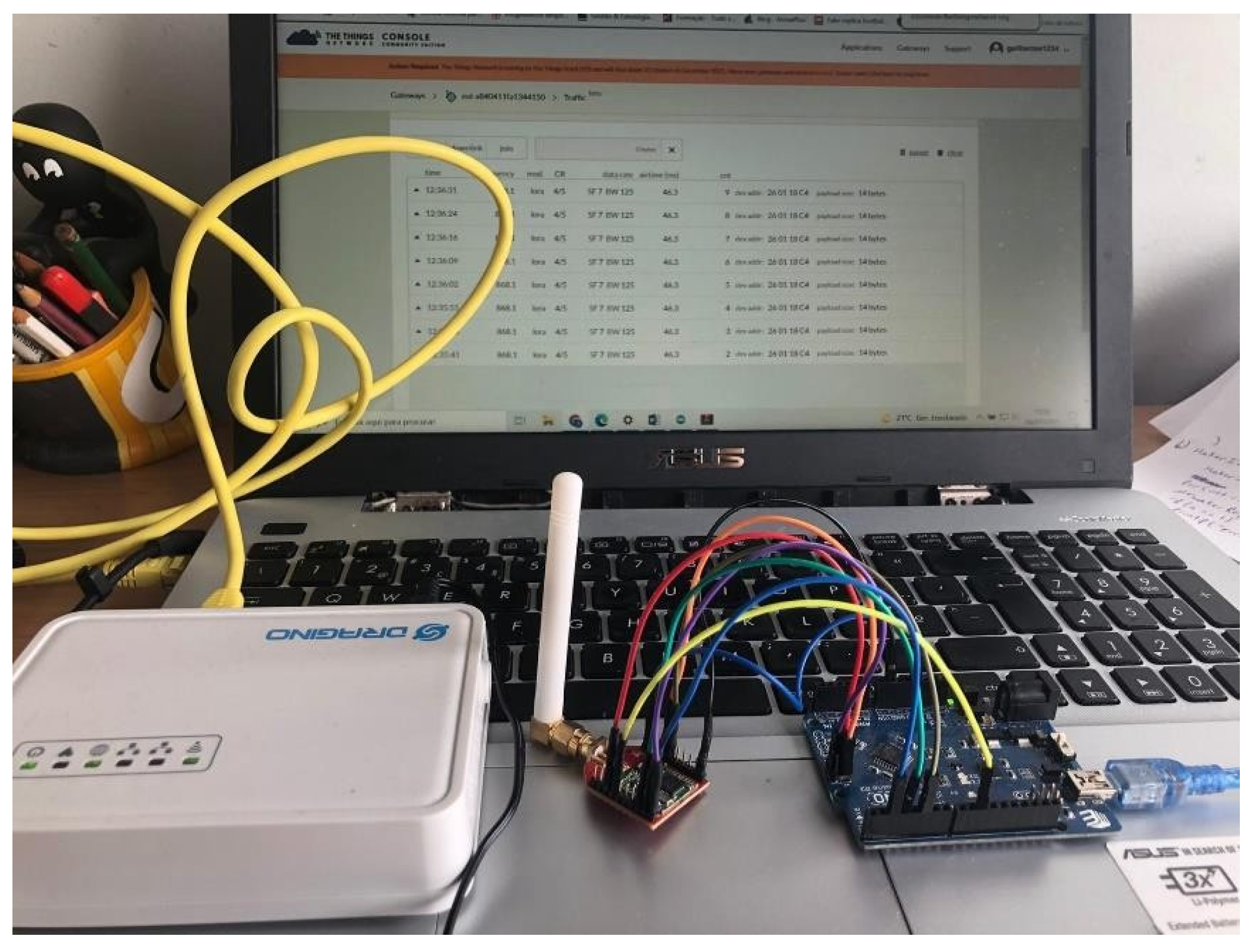
The hardware used was: LG02 Dual Channels LoRa Gateway [22], LoRa Bee SX1276 [22] and Arduino UNO REV3 [23].
The LoRa Bee module consists of an SX1276 transceiver, which allows the user to send data. This module enables transmission in multiple modes, working at a frequency of 868 MHz, thus supporting the LoRa networks spread spectrum technology and supporting I/O voltage values of 3.3V. The Sensitivity of this module can be seen in Table 3.
The LoRa Bee module was working in a class A operational mode (base class for all LoRa devices). Class A devices support bi-directional communication, but the downlink (server to device) communication must follow an uplink (device to server) communication from the device. This means the server can only send data to the device when it’s expecting to receive it, which is a short window after it sends data. Some key characteristics of a Class A end device:
- ▪
- Uplink Transmission: A Class A device can send an uplink message at any time. The uplink slot is scheduled by the end device itself based on its need.
- ▪
- Downlink Transmission: Once the uplink transmission is completed, the device opens two short receive windows for receiving downlink messages from the network. There is a delay between the end of the uplink transmission and the start of each receive window, known as RX1 Delay and RX2 Delay, respectively.
- ▪
- Low Power Consumption: Class A end devices have very low power consumption. Therefore, they can operate with battery power. They spend most of their time in sleep mode and usually have long intervals between uplinks.
- ▪
- High Downlink Latency: Class A devices have high downlink latency, as they require sending an uplink to receive a downlink.
The LoRa Bee module has been connected to the Arduino (SPI connection), enabling long-distance communication, and guaranteeing good connection stability and consistency. It has encryption algorithms that prevent data from being intercepted and compression algorithms that allow small data to be transmitted, making the process faster and more efficient, thus providing good sending reliability.
The LG02 is a two-channel LoRa Gateway. It allows the LoRa network to be connected to Wi-Fi, Ethernet, 3G and 4G. This gateway can support the LoRaWAN protocol and uses the same transceiver module (SX1276) to communicate with the node. The computational design of the LG02 is done using Linux, which allows the LoRa to work in full duplex LoRa mode and increase communication efficiency.
The LG02 gateway can support various modes, such as: LoRa repeater mode, MQTT mode, TCP / IP client mode, TCP / IP server mode. This equipment is often used to extend the signal to other devices on a LoRaWAN or Wifi network.
The LoRa gateway has been registered and configured in the The Things Network (TTN) [25], as has the end device (Arduino with LoRa Bee)
Figure 14.
Hardware for experimental experience.
5.2. Experimental Test Scenarios
In our study we have created a scenario of inter-SF interference, transmitting sequentially packets of different sizes and different SFs, (pseudo) ramdomly. The goal was to create a real scenario of having several devices transmmiting different types of information at different distances in a way that packets could overlap, leading to a scenario of high probability of packet losses. Different fading propagation conditions were also created tested in a way that we could study the implication of the signal strenght (evaluated by RSSI) in the reliability of our link for this scenario conditions, and also the implication of possible SIR reduction when comparing the LOS and in a the NLOS scenarios (leading to an increase in probabilities of inter-SF interference). The impact of the payload size on the choice of the best spreading factor for each of the conditions tested, was also analysed.
The criteria for choosing each position, both for the gateway and the LoRa module, were based on locations that made it possible to test the impact on our link of factors such as: vegetation, obstacles, building features, distance between gateway and module, and connection with and without line of sight at different distances.
We tested for each one of the distances of:
- ▪
- 20, 40 and 60 meters
Different spreading factors of:
- ▪
- 7, 9 and 12.
And, for each one of these distances and each one of these SFs we changed the amount of the payload size, consequentially:
- ▪
- 14, 32 and 51 bytes.
The tests were carried out in 3 scenarios:
- ▪
- Line of Sight (LOS).
- ▪
- Non-Line of Sight (NLOS), being vegetation the factor for signal absorption, scattering and attenuation.
- ▪
- Non-Line of Sight (NLOS), being a concrete wall the factor for fading and shadowing.
The first test was carried out at 20 meters between the gateway and the LoRa module. Here both devices were in line of sight. To understand the impact of interference on given chosen spreading factor and the Effects of Collisions, at 20 meters with line of sight (LOS), we have carried out the tests with SF7, SF9 and SF12 and for each spreading factor we have changed the size of the data to be sent (14 bytes, 32 bytes and 51 bytes).
At 40 meters and with line of sight, we repeated the tests for the same SFs with SF7, SF9, SF12. For each spreading factor we have changed the size of the data to be sent (14 bytes, 32 bytes and 51 bytes).
After, we have increased again the distance between the LoRa module and the Gateway to 60 meters. The end node device and the Gateway were also in line of sight. And again, we performed the tests again with SF7, SF9, SF12 and for each spreading factor we have changed the size of the data to be sent (14 bytes, 32 bytes and 51 bytes).
In this way, we were able to compare values and try to understand the influence that distance and the payload size can have in the transmission of these packets, as well as the impact of interference at given chosen spreading factor.
Once the line-of-sight measurements were complete, we tested the two scenarios of NLOS using a distance between the LoRa module and the Gateway of 60 meters. Has it been explained before, the two situations of this scenario are one with vegetation and another with a concrete wall of a building.
At 60 meters without line of sight and vegetation, we had once again carried out the tests with SF7, SF9, SF12 and for each spread factor we have changed the size of the data to be sent (14 bytes, 32 bytes and 51 bytes). In this way, we were able to compare values with the scenario of LOS (at 60m) and try to understand the influence that the vegetation can have in signal absorption, scattering and attenuation, as well as the variation in the spreading factor for the conditions of the reference scenario.
To finalize the tests, and also at 60m, we used a concrete wall of a building aiming this way to understand how different types of obstructions can affect signal strength and quality of the signal in NLOS conditions. In this case, to study the impact of interference at given chosen spreading factor and the Effects of Collisions, we have, once again, carry out the tests with SF7, SF9 and SF12 and for each spread factor we changed the size of the data to be sent (14 bytes, 32 bytes and 51 bytes).
5.3. LOS Results
In this first scenario, the configurations used are summarized in Table 4.
We began by studying the influence of the payload size for each SF on the received signal strength (where RSSI indicates the level of the received signal strength), and the relationship of a given chosen SF (with a certain payload size) in ToA. The gain of the antenna of the transceiver SX1276 was 1.5 dBi and for the LG02 the same. Figure 15, Figure 16 and Figure 17 show the direct results taken from measurements under these conditions. To note that from the 10 packets sent, some of them had very similar values, that’s why some “dots” are not seen.
As expected, the larger the SF used, the greater its ToA (symbol time is directly proportional to SF and the higher the symbol time the higher the ToA).
In terms of RSSI, we can see that, for the same distance, different SFs, and payload sizes we have at:
- ▪
- 20m: Highest value for Sf=7 with 14 Bytes (-63 dBm). Lowest for (also) SF=7 and 51 Bytes (-91 dBm).
- ▪
- 40m: Highest value for SF=9 with 51 Bytes (-74 dBm). SF=12 with 51 bytes also achieves a good result at this distance (-76 dBm). Lowest for SF=7 with 51 Bytes (-106 dBm). Yet this value it’s just for one packet. In all the other 9 the worst value was -89 dBm.
- ▪
- 60m: Highest value for SF=7 with 32 Bytes (-82 dBm). Lowest for both SF=9 with 12 and 32 Bytes (-106 dBm).
It’s revealing that the payload size has quite an impact on the RSSI. At 20m and for the same spreading factor, SF=7, having a difference of 28 dB (-63-(-91) =28) between the best packet (14 bytes) and the worst (51 bytes) it’s quite a lot. The best values for SF=7 and 14 Bytes are not so different (-63 dBm) of the best values of SF=7 and 51 Bytes (-74 dBm) but the worst packets of each payload size can be 23 dB (-68-(-91) = 23) down, for the worst case.
Looking for the distance of 20m and considering payloads with just 14 bytes, the SF=7 at 20m has the best performance, while for 32 and 51 bytes the SF=9 would be the better choice.
In the distance of 40m and making the same considerations the SF=7 will have better performance for payloads sizes of 14 bytes while for packets with 32 and 51 bytes, SF=9 perform better.
Looking for the distance of 60m we have some mixed results. For 14 bytes SF=7 and 9 are quite similar (with a slightest advantage for SF7), while for 32 and 51 bytes, SF=7 performs better.
Considering just each one of the spreading factors, for the 3 distances tested and for the different payload sizes we achieved the following results:
- ▪
- SF7 has the best result of RSSI for 14 bytes at 20m (-63 dBm) and the worst for 51 bytes at 60m (-95 dBm).
- ▪
- SF9 has the best result for 32 bytes at 20m (-67 dBm) and the worst for 32 bytes at 60m (-106 dBm). Yet this value it’s just for one packet while the worst of the other 9 packets was -96 dBm.
- ▪
- SF12 has the best result for 20m (-73 dBm) and payload of 51 bytes and the worst for 14 bytes at 60m (-106 dBm). Yet, 8 of the 10 packets were higher than -102 dBm.
From here we can consider that SF7 perform quite well for the shortest distance (20m) and for the smallest packet sizes tested (14 bytes), while SF9 at 20m and 40m and for the packets size of 32 and 51 bytes it’s the best option. SF12 for the longest distance (60m) and for the smallest packet (14 bytes) have the worst performance.
Some more insights: Among the several distances tested, the difference between the highest value (-63 dBm for SF=7 (14 Bytes) at 20m) and the lowest (-106 dBm for SF=12 (14 Bytes) at 60m) is of 40dB, which reveals quite a big difference between this two different SFs (7 and 12) and makes us consider the right choice of the SF for this conditions critical (e.g the SF7 for 60m have the his highest value=-82 dBm (at 32 bytes) and the lowest -95 dBm (at 51 bytes). And in this case, we have a difference of 13 dB.
On other hand and considering that at different distances, different SFs might be sending packets received by the gateway, inter-SF interference must be considered. If we consider that for 20m an SF7 will be the logical choice, signals with an RSSI between -63 and -68 dBm would be arriving to the gateway. If a more distant node with SF9 is sending packets to the same gateway, in our case we would have values of RSSI between -77 dBm and -83 dBm for 40m or -86 to -96 dBm in the case of the same SF9 to 60m. Observing the values in Table 2, if a desired packet with SF9 is arriving at the same time as a packet with SF7, for the SF9 packet to be demodulated successfully, a separation of at least 27 dB would need to be guaranteed between the RSSI signals from the two different FS. And it’s far from that. Thus, we are facing a scenario of probable inter-SF interference and packet loss.
Next, we have studied, more in particular, the impact of the choice of SF for different file sizes on their ToA. The results obtained were in line with the expectations, and with increasing SF, ToA increases considerably. In relation to the impact of file size, ToA is also greater and grows proportionally, as can be seen in Figure 18. A very important factor in the choice of SF is the fact that the larger the SF used, the greater the ToA, (which can lead to more collisions as the channel is occupied for longer).
Figure 19, Figure 20 and Figure 21 makes a graphical resume of what has been said about the values of RSSI for different SFs, payload sizes and distances. RSSI according to different data size and different distances for SF7/9/12.
In the case of SF7 (Figure 19), we can see that for 20 metres, as the file size increases, the quality of the connection decreases, since the power received is lower. For the 40 and 60m cases, the connection quality is lower than for 20m, but the values of RSSI are more stable.
In SF9 (Figure 20), we obtained the more balanced results for the three scenarios tested since the quality of the connection is very stable This could be a viable solution for a scenario where you want to send packets of various sizes and you need signal stability.
For SF12 (Figure 21), at distances of 20 and 40 metres, the quality of the connection improves as the file size increases and its values converges at 51 bytes, while at 60 metres the value oscillates between -98 and -90 dBm.
Thus, and reaffirming what was said before, given that for medium-distance connections (40m), the use of SF9 is ideal and with the variation in file size there is only an oscillation of at least. In the case of the SF7 measurement, the impact of varying the file size is noteworthy, even if for larger files (and distances) the quality of the connection doesn’t varies much, which can lead to very interesting optimisations. SF12 is also quite stable for the two bigger file sizes tested. We were also able to conclude that larger SFs can handle larger files.
Then, we studied the possibility of packet loss for various values of SF, payload sizes and distance (Figure 22). And even in LOS scenario, for 60m, SF=12 and the payload of 51 bytes, we can already observe packet loss due to the conditions described in the beginning of the Section 5.2. The test was repeated several (5) times always with the same result. All the tests done for SF12, and the three different payload sizes were repeated 5 times, so in total 50 packets for each data size were sent and, in the end, we observed that for SF12 and 51 bytes at the distance of 60m, we lost one packet in 10, leaving to a PDR or 90%. The long time on air of packets using SF12 and a 51-byte payload increased the probability of collisions with other packets transmitted with different SFs and payload sizes (with lower ToA), thus leading to connection degradation and loss of packages for transmissions with these characteristics.
5.4. NLOS Results
After carrying out the measurements for the previous scenario and stablishing a pattern we have now checked the impact of obstacles in the quality of our link and the possibility of also having some number of packets lost for the same SFs and payload sizes. The distance tested will only be one (60m) of the previous three. To do this, we visualized two types of scenarios: sparse vegetation and a building (concrete wall) between the module and the gateway. The configurations of Table 5 resume the settings.
As in the previous scenario, we began by studying the influence of ToA on the RSSI of the payload size for each SF on the received signal strength of the connection, considering the size of the files sent and the relationship of a given chosen SF in ToA. Comparing Figure 23 and Figure 24 with the previous figures, we can see that, the fact that there is no line of sight does not alter the ToA values of the connection. As far as RSSI is concerned, the values obtained in the case of the NLOS with vegetation, the best performance at this distance and for the three packets sizes it’s the SF7, with the highest value being -76 dBm for 32 bytes and the worst -91 dBm for the case of the 51 bytes. This values, are all better than the ones recorded previously, for the same distance at 60m in LOS, and for the three different packets sizes (with SF7).
However, the building concrete wall will introduce a greater decay in the quality of the connection than all the previous situations study until now.
And analysing the results for the case of the building’s concrete wall, we can see that for the three packet sizes, both the transmission with SF7 and the transmission with SF12 have very similar values, but with SF12 having the smallest variance between the highest values and the lows for the three packet size situations. And choosing the SF12 spreading factor could be the best option in these cases. For SF12, the highest value is -94 dBm (51 bytes) and the lowest is -102 dBm (14 bytes), thus showing very robust behaviour under these conditions. For SF7, the highest value is -92 dBm (for the 32 byte packet) while the worst is -103 dBm (also for 32 bytes). This stability of SF12 values is also an advantage, if we think about the possibility of inter-SF interference, because a connection with the latter’s characteristics is less likely to have inter-SF interference (arising from communications with different SF), than one with more dispersed values, thus resulting in an advantage for the designer.
Next, we looked, more in particular, at the effect of SF on ToA for various file sizes. As mentioned earlier, ToA only depends on the SF used and the size of the file (it also depends on the frequency and BW used, but these are fixed values in this scenario) being sent, so as the parameters are the same as in the LOS scenario, there was no variation in ToA values (Figure 25).
As in the previous scenario, Figure 26 (vegetation as an obstacle) and Figure 27 (concrete wall of a building as an obstacle) makes a graphical resume of what has been said about the values of RSSI for different SFs and payload sizes at 60m. It compares the impact on connection quality of varying file sizes at this distance, using the average value of the 10 packages sent. It is important to emphasise that in the case of the building as an obstacle, SF9 performed worse than SF12.
Finally, the number of packets sent and received in both obstacle scenarios was analysed. In the case of the vegetation obstacle (Figure 28) there was only the loss of one packet in SF12 for a 51-byte file. To resolve any doubts, the test was repeated 5 times, with a total of 50 packets sent. And the result was always the same.
With the concrete wall of the building has an obstacle (Figure 29), there was also the loss of one packet in SF12 and, this time, for all file sizes. As in the LOS situation and the previous one, we decided to send more (5 times) packets, for a total of 50, and the result was the same. So, if by one hand the stability of values could be an advantage for the SF12 choice, on the other hand we lost packets, and in situations that it’s important not to lose packets (e.g., Surveillance systems, Energy monitoring and management - smart grids, Autonomous vehicles, Monitoring of electrical signals) the option for the SF7 will be the correct one. Considering the problem of inter-SF interference, we see that, for the three SFs tested and, in a case, where a gateway may be receiving communications packets from different SFs with different packet sizes (at the same distance), the RSSI values are much closer together than in the case of the LOS scenario, making this case the worst for the SIR (lowest).
Packet loss in the case of the NLOS (concrete wall) scenario of SF12 and 51 bytes was expected. Considering that previously for the case of payload with 51 bytes and SF12, in the LOS and NLOS (with vegetation) scenarios, it had already been verified, the loss of a packet in this case of the concrete wall also happened. The long ToA led to this.
Furthermore, in this latter scenario, signals must penetrate, diffract, or reflect around obstacles (such as concrete walls or objects), which can cause multipath propagation (in addition to normal attenuation). Signals will reflect off surfaces and arrive at the receiver at different times. If we think that in addition, we have a long ToA (which for the case of SF12 and the three data sizes, varies from 1155ms (14 bytes) to 2465ms (51 bytes)) we will most likely cause destructive interference to the signals and increase thus the probability of collisions and packet loss for the case of SF12 and the other two data sizes (14 and 32 bytes), thus leading to a result in the PDR, for each one, of 90%.
6. Conclusions
This study aimed to verify the effects of collisions and interference in LoRaWAN, regarding the periodicity of transmissions and the payload sizes and also to use measuring tools like RSSI, ToA and PDR to test the reliability of a LoRaWAN link in real tested scenarios and to validate this measuring tools for a good quality of LoRa signal.
RSSI gave us a measure of the reliability of our link. First, we have set a pattern by stablishing the values of RSSI, ToA and PDR in a Line-of-Sight scenario, for different SF’s, payload sizes and distances. After we had made experiments at the distance of 60m but in a non-line of sight scenario (with vegetation and concrete wall). In the end, PDR gave us a more realistic view of the reliability of our link where RSSI was always good or at least acceptable, and yet we detect loss of packets due to the set of conditions created (inter-sf interference, fading, shadowing, multipath and a long ToA (for the case of SF12 with the three different packet sizes). If these experiments tell us anything, it is that the (theoretical) choice of a given SF, for a given link is never obvious, and the designer must always do field tests to validate his choices and optimize his network(s).
We could observe that the larger the payload length of the packets and the higher the SFs, had result in longer ToA. Specially looking for the higher values of ToA (SF12) we can infer that for a network with multiple devices at greater distances of the gateways, the probability of losing packets due to latency is quite real. Thus, limiting the scalability at these distances. On our experiment, with only one end device and 10 packets sent, (and with short distances) only in a situation of NLOS (with buildings) this could become a problem.
On the other hand, and looking at the (very close) RSSI values obtained in our short distance scenario we can say that the probabilities of interference and collisions are established, due to inter-SF interference and this is a factor that will limit the scalability of the network to the end nodes at a very close distance from the gateways (they will interfere with the more distant ones).
A balance between emitted and received power will, therefore, be critical in a large network, especially at the two “extreme” points. This balance is important because Adaptive Data Rate (ADR) don’t solve everything. Ensuring this balance helps prevent the nearest nodes from suffering from inter-SF and intra-SF interference from the farthest nodes, and vice versa. This balance also mitigates the issues of latency and poor signal strength experienced by the farthest nodes; this is a good way for future work.
That’s why in a next study we intend to increase the distances and expand the network number of devices. The further extension of this scenarios, already proposed, will leave to further validations of this tools in all kinds of scenarios. This will lead us to also test the scalability of a network with several end nodes and different SFs at greater distances and aspects like collisions and interference in the performance of does networks.
Conflicts of Interest
The authors declare no conflicts of interest.
References
- Andri Rahmadhani and Fernando Kuipers (Del. University of Technology), “Understanding collisions on LoRaWAN”, Conference: the 12th International Workshop, pag.1, 2018.
- Daniele Croce, Michele Gucciardo, Stefano Mangione, Giuseppe Santaromita, Ilenia Tinnirello, “Impact of LoRa Imperfect Orthogonality:Analysis of Link-level Performance”. Available online: https://www.researchgate.net/publication/319486965_Impact_of_Spreading_Factor_Imperfect_Orthogonality_in_LoRa_Communications, (accessed 17/05/2024).
- Oracle - “What is IoT?”. Available online: https://www.oracle.com/internet-of-things/what-is-iot/ (accessed on 21/03/2024).
- Yuya Ishida, Daiki Nobayashi, Takeshi Ikenaga, “Experimental Performance Evaluation of the Collisions in LoRa Communications”, 2018 International Conference on Computational Science and Computational Intelligence (CSCI).
- G. Ferré. Collision and packet loss analysis in a LoRaWAN network. 25th Eur. Signal Process. Conf. EUSIPCO 2017, vol. 2017-January, pp. 2586–2590, 2017.
- Semtech Corporation, “AN1200.22 LoRa™ Modulation Basics”, May 2015.
- LoRa Alliance. Available online: https://lora-alliance.org/wp-content/uploads/2020/11/what-is-lorawan.pdf, (accessed 9/4/2024).
- Semtech. Available online: https://Semtech Blog: LoRa Delivers Internet of Things Capabilities Worldwide, (accessed on 17/05/2024).
- Rakwireless. Available online: https://news.rakwireless.com/lora-css-vs-lora-fhss/, (accessed on 17/05/2024).
- Semtech Corporation, “LoRa® and LoRaWAN®: A Technical Overview”, December 2019 (accessed 17/05/2024).
- 11. K. Olsson and S. Finnsson, Exploring LoRa and LoRaWAN: A suitable protocol for IoT weather stations?, Master’s Thesis, Department of Electrical Engineering, Chalmers University of Technology, Sweden, 2017.
- T. Elshabrawy e J. Robert, “Evaluation of the BER Performance of LoRa Communication using BICM Decoding”, 2019 IEEE 9th International Conference on Consumer Electronics (ICCE-Berlin), p.162-167, 2019.
- LoRa. Available online: https://lora.readthedocs.io/en/latest/, (accessed 18/5/2024).
- The Things Network. Available online: LoRa Physical Layer Packet Format | The Things Network, (accessed 17/5/2024).
- The Things Network. Available online: https://www.thethingsnetwork.org/docs/lorawan/spreading-factors/, (accessed 17/5/2024).
- Courjault, J.; Vrigenau, B.; Berder, O.; Bhatnagar, M. A Computable Form for LoRa Performance Estimation: Application to Ricean and Nakagami Fading. IEEE Access 2021, 9, 81601–81611. [Google Scholar] [CrossRef]
- Dias, C.F.; Lima, E.R.D.; Fraidenraich, G. Bit error rate closed-form expressions for LoRa systems under Nakagami and Rice fading channels. Sensors 2019, 19, 4412. [Google Scholar] [CrossRef] [PubMed]
- Claire Goursaud, Jean-Marie Gorce, “Dedicated networks for IoT: PHY / MAC state of the art and challenges”. Available online https://hal.science/hal-01231221, (accessed 18/05/2024).
- Poonam Maurya, Aatmjeet Singh and Arzad Alam Kherani “A review: spreading factor allocation schemes for LoRaWAN”, May 2022, available online. https://link.springer.com/article/10.1007/s11235-022-00903-4, (accessed on 17/05/2024).
- N. Abramson and F.F. Kuo, Eds., Computer-Communication Networks, Englewood Cliffs, NJ: Prentice-Hall, Chapter 13, 1973.
- R. Metcalfe, Steady state analysis of a slotted and controlled ALOHA system with blocking, Proc. 6th Hawaii Int. Conf. Sys. Sci., January, 1973.
- Dragino. Available online: https://www.dragino.com/ (accessed on 9/4/2024).
- Arduino. Available online: https://www.arduino.cc/ (accessed on 11/3/2024).
- Semtech Corporation. Available online: https://www.semtech.com/products/wireless-rf/lora-connect/sx1276#features, (accessed 09/04/2024).
- The Things Network. Available online: https://www.thethingsnetwork.org/ (accessed on 23/2/2024).
Figure 1.
Three scenarios tested: first – left, second – center and third – right (extracted from [4]).
Figure 1.
Three scenarios tested: first – left, second – center and third – right (extracted from [4]).
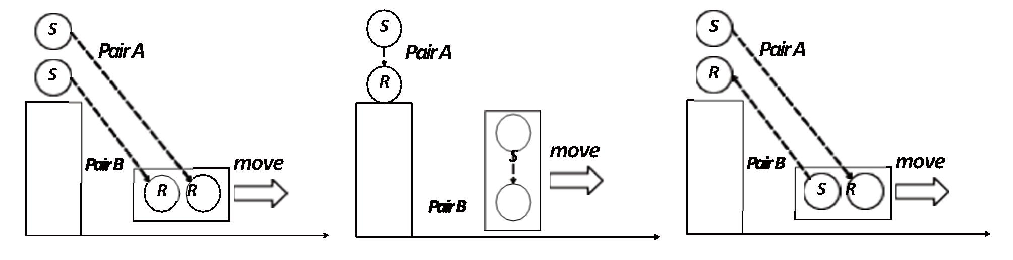
Figure 2.
Collision probability for p = 100, SF = 12 and Tonn= 1s and 2s.
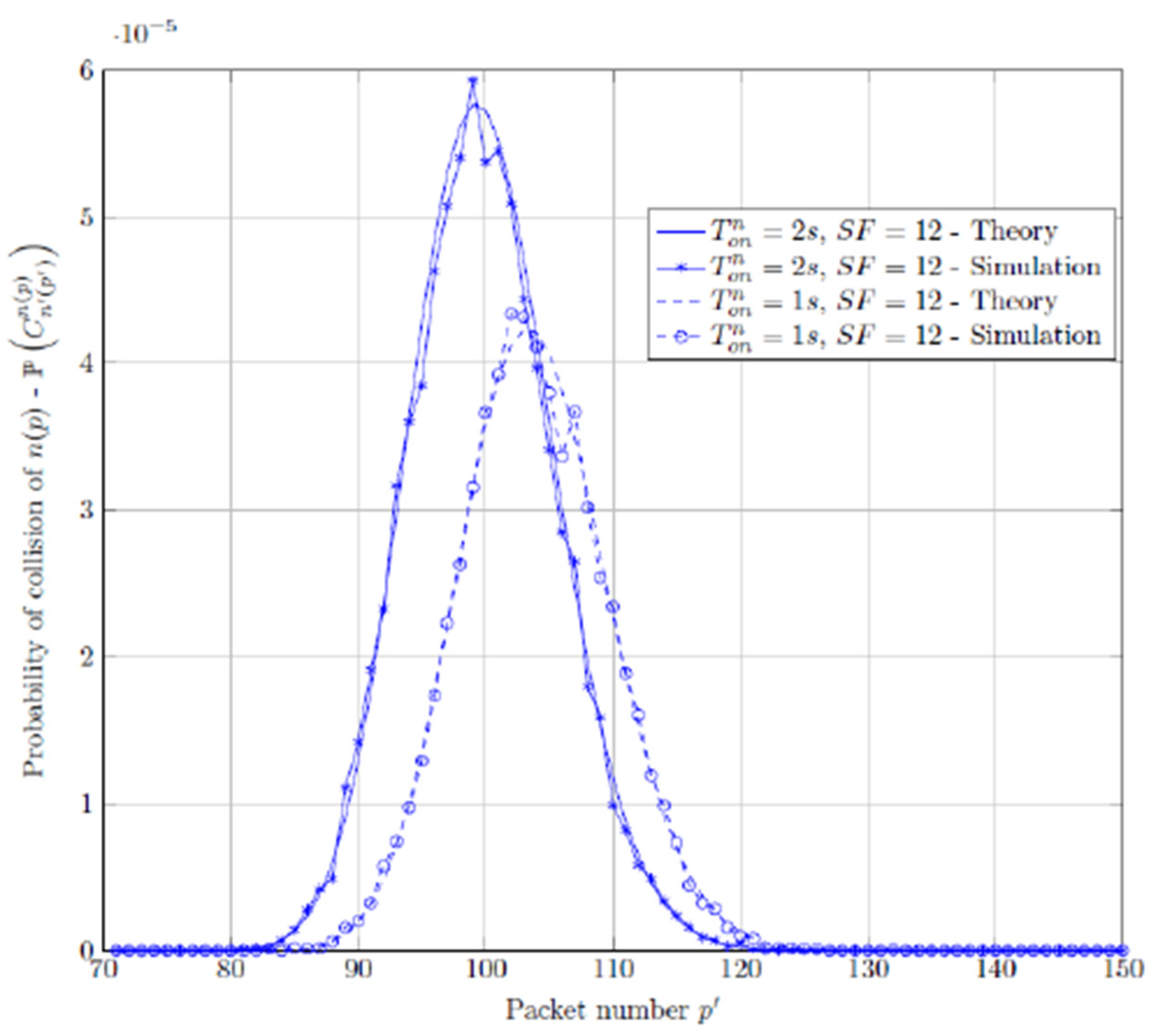
Figure 4.
Graphical representation of an up-Chirp.
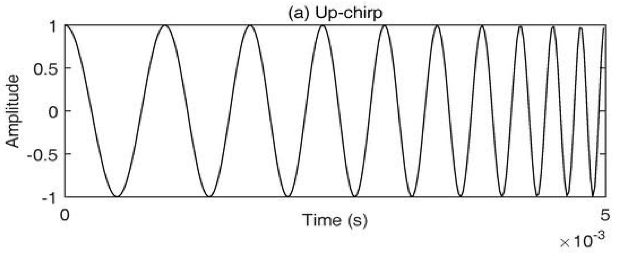
Figure 5.
Graphical representation of a Down-Chirp.
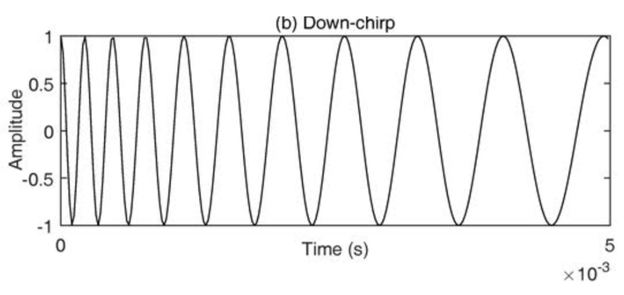
Figure 6.
Representation of an up-chirp, where B represents the Bandwidth and Ts the symbol time (modified from [12]).
Figure 6.
Representation of an up-chirp, where B represents the Bandwidth and Ts the symbol time (modified from [12]).

Figure 7.
SF defines the number of bits that can be encoded by a symbol (at left an unmodulated signal and at right a modulated one) (modified from [13]).
Figure 7.
SF defines the number of bits that can be encoded by a symbol (at left an unmodulated signal and at right a modulated one) (modified from [13]).
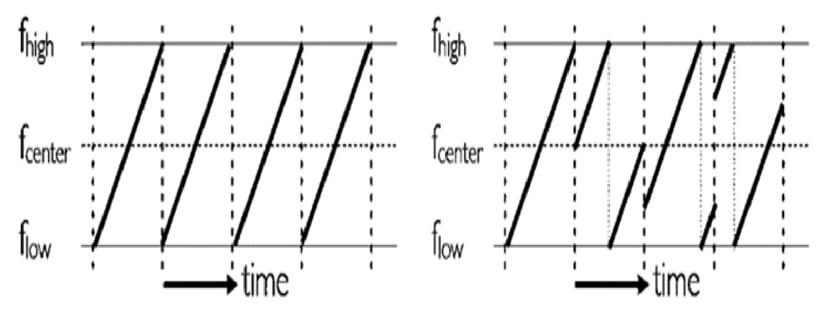
Figure 8.
Bit rate as a function of SF.
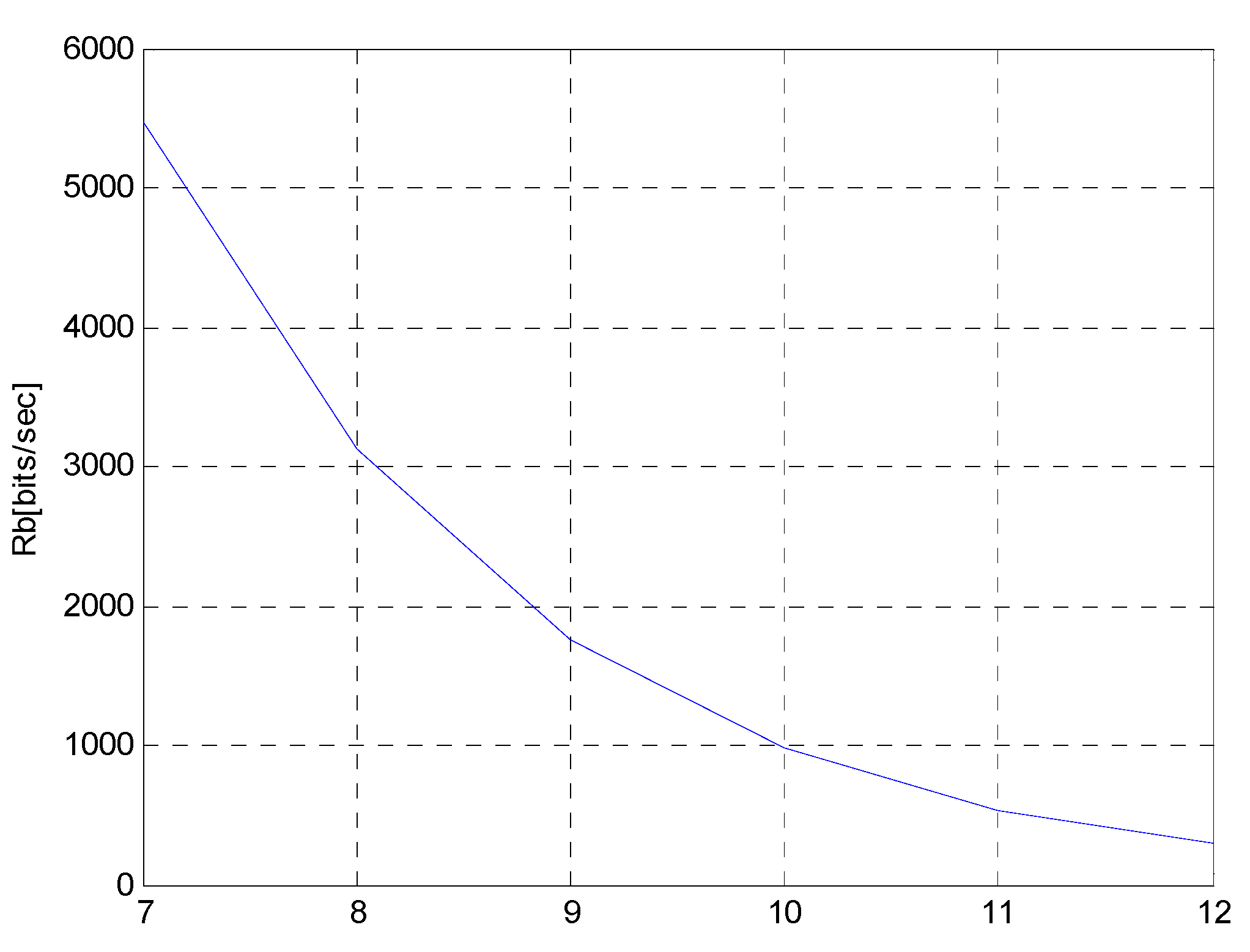
Figure 9.
Bit rate according to SF and varying CR, for a bandwidth of 125kHz.
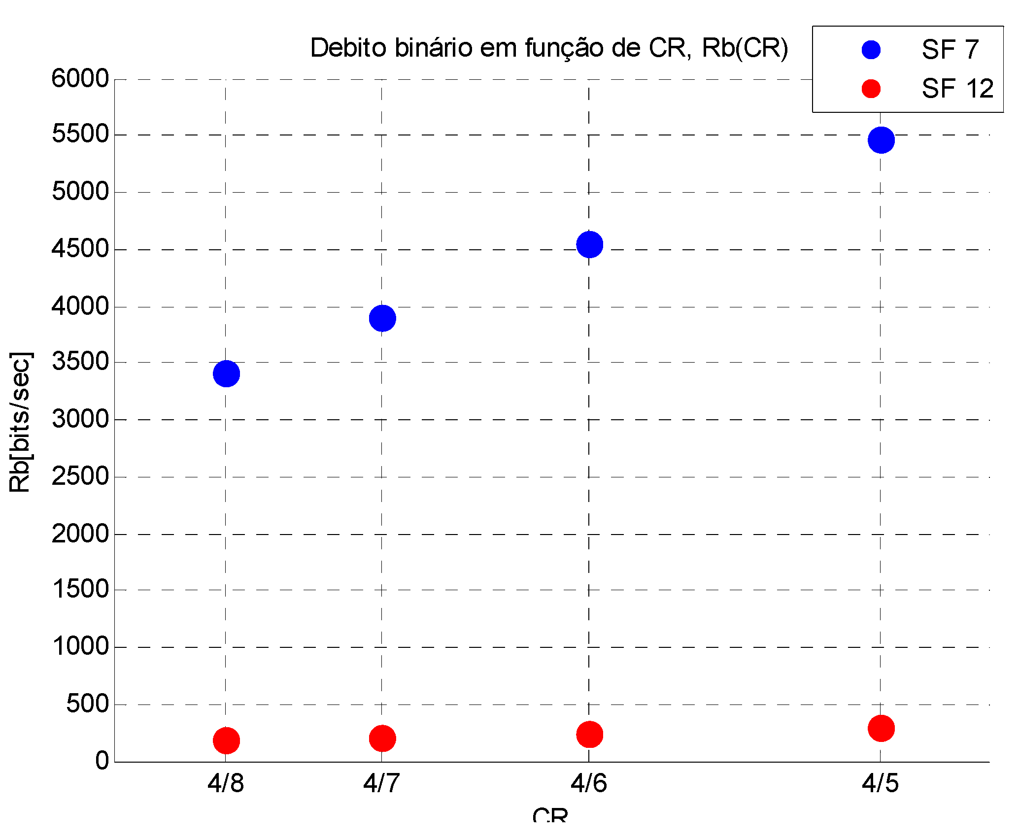
Figure 10.
Bit rate to SF=7 and 12 and varying BW, for a CR of 4/5.
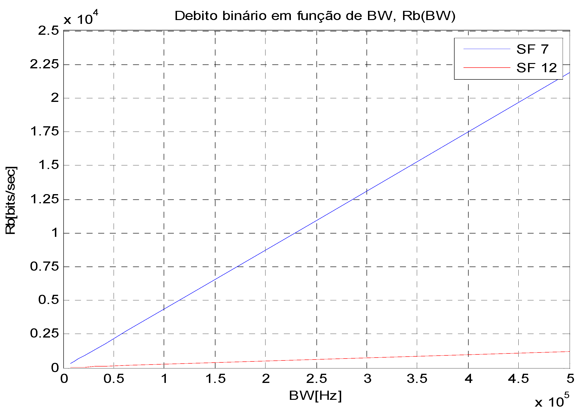
Figure 11.
Fields of a LoRaWAN Data Message.
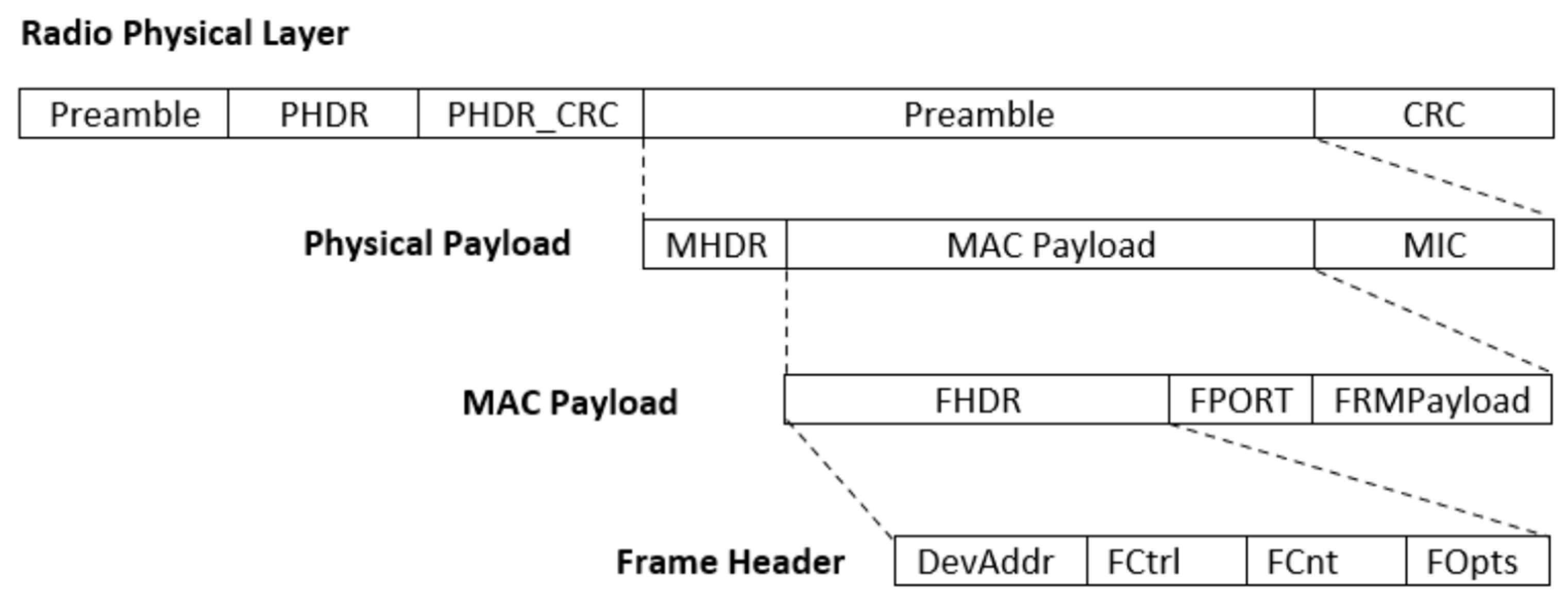
Figure 12.
Stucture of LoRa packet format with CR n ∈ {1..4}.
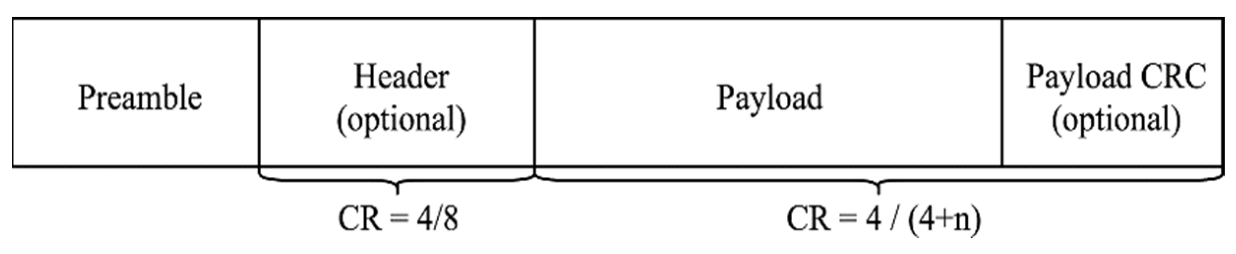
Figure 13.
MAC protocol schematic (adapted from [7]).
Figure 13.
MAC protocol schematic (adapted from [7]).

Figure 15.
Influence of the payload size (for SF7) on ToA and on the RSSI (aggregated by payload size).
Figure 15.
Influence of the payload size (for SF7) on ToA and on the RSSI (aggregated by payload size).

Figure 16.
Influence of the payload size (for SF9) on ToA and on the RSSI (aggregated by payload size).
Figure 16.
Influence of the payload size (for SF9) on ToA and on the RSSI (aggregated by payload size).
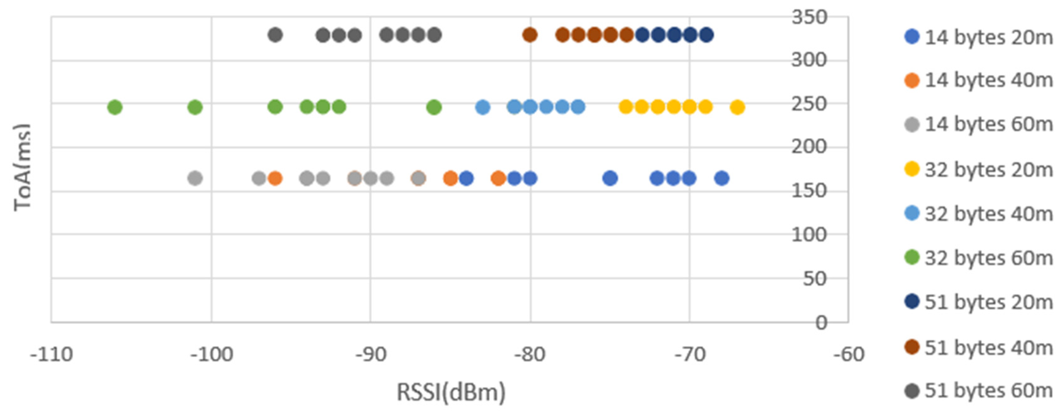
Figure 17.
Influence of the payload size (for SF12) on ToA and on the RSSI (aggregated by payload size).
Figure 17.
Influence of the payload size (for SF12) on ToA and on the RSSI (aggregated by payload size).
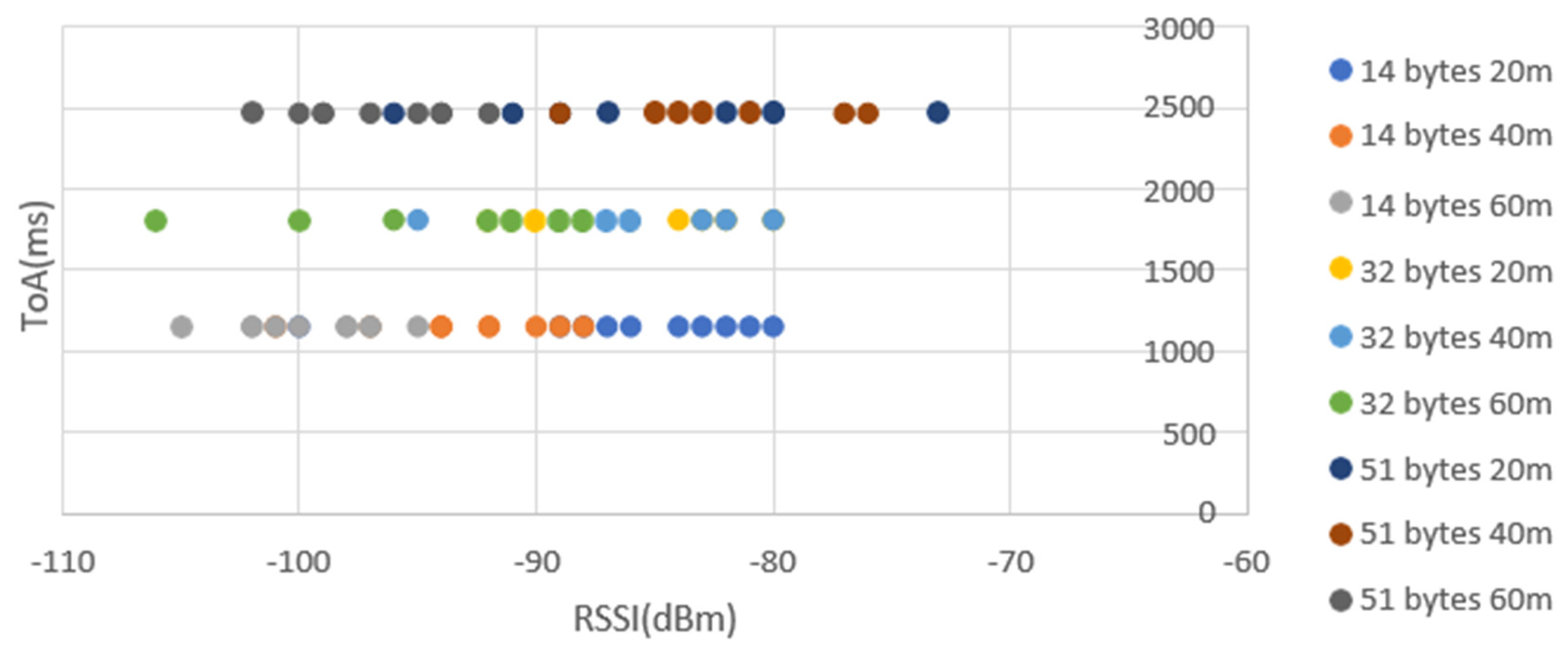
Figure 18.
ToA according to SFs and data size.
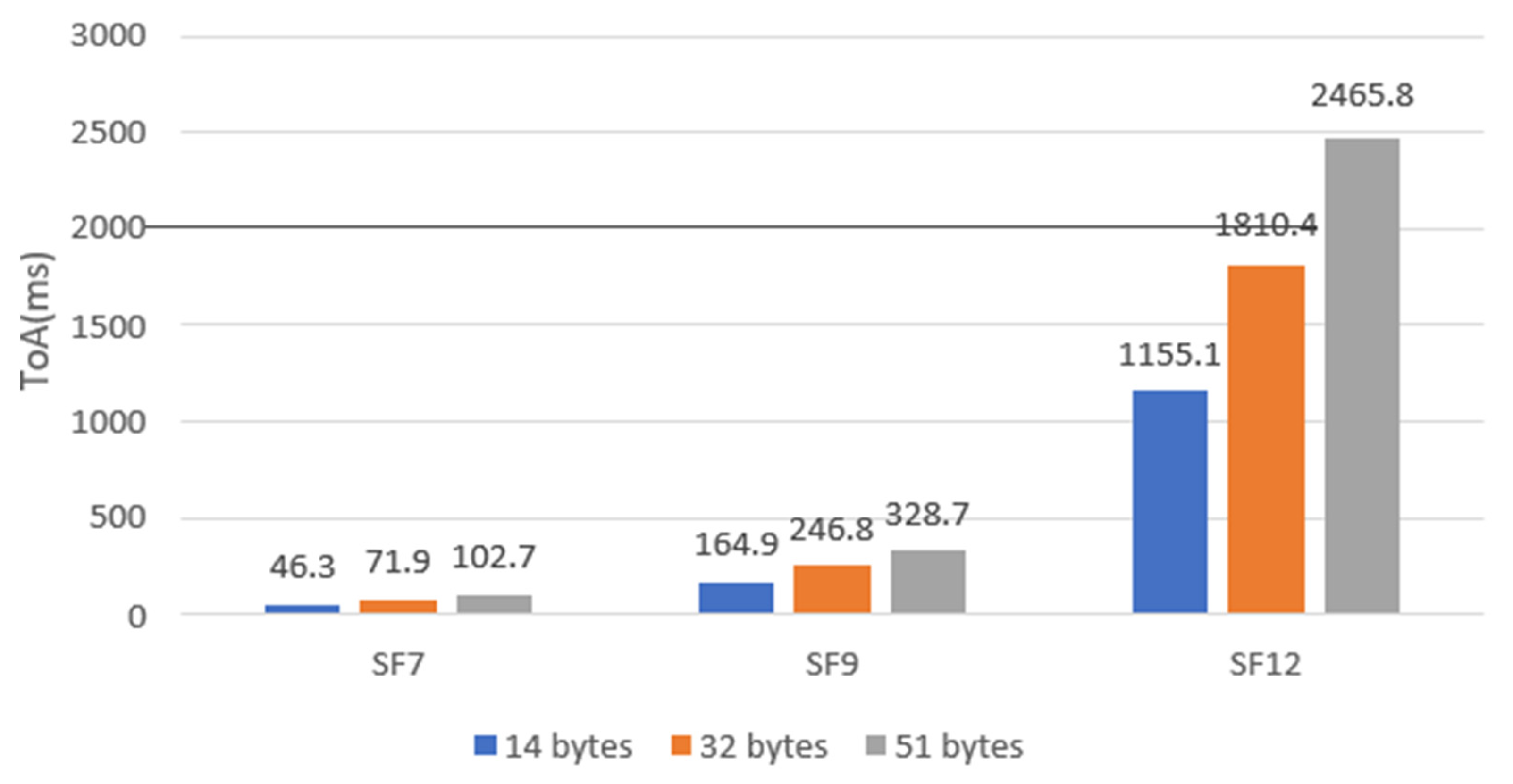
Figure 19.
RSSI according to different data size and different distances for SF7.
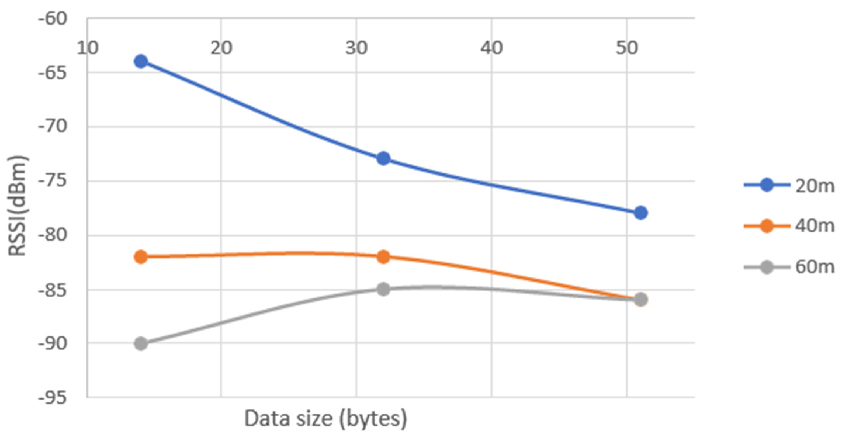
Figure 20.
RSSI according to different data size and different distances for SF9.
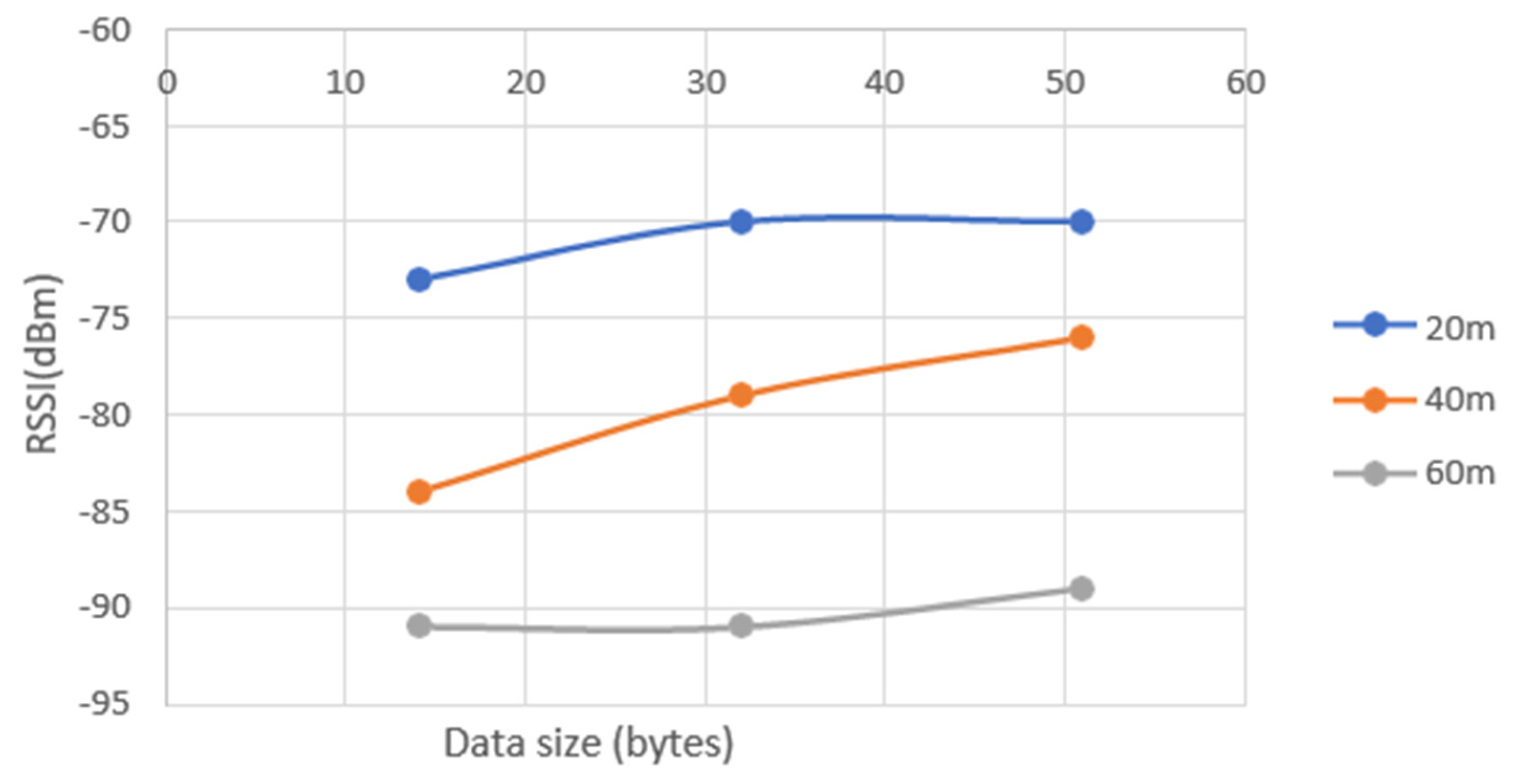
Figure 21.
RSSI according to different data size and different distances for SF12.
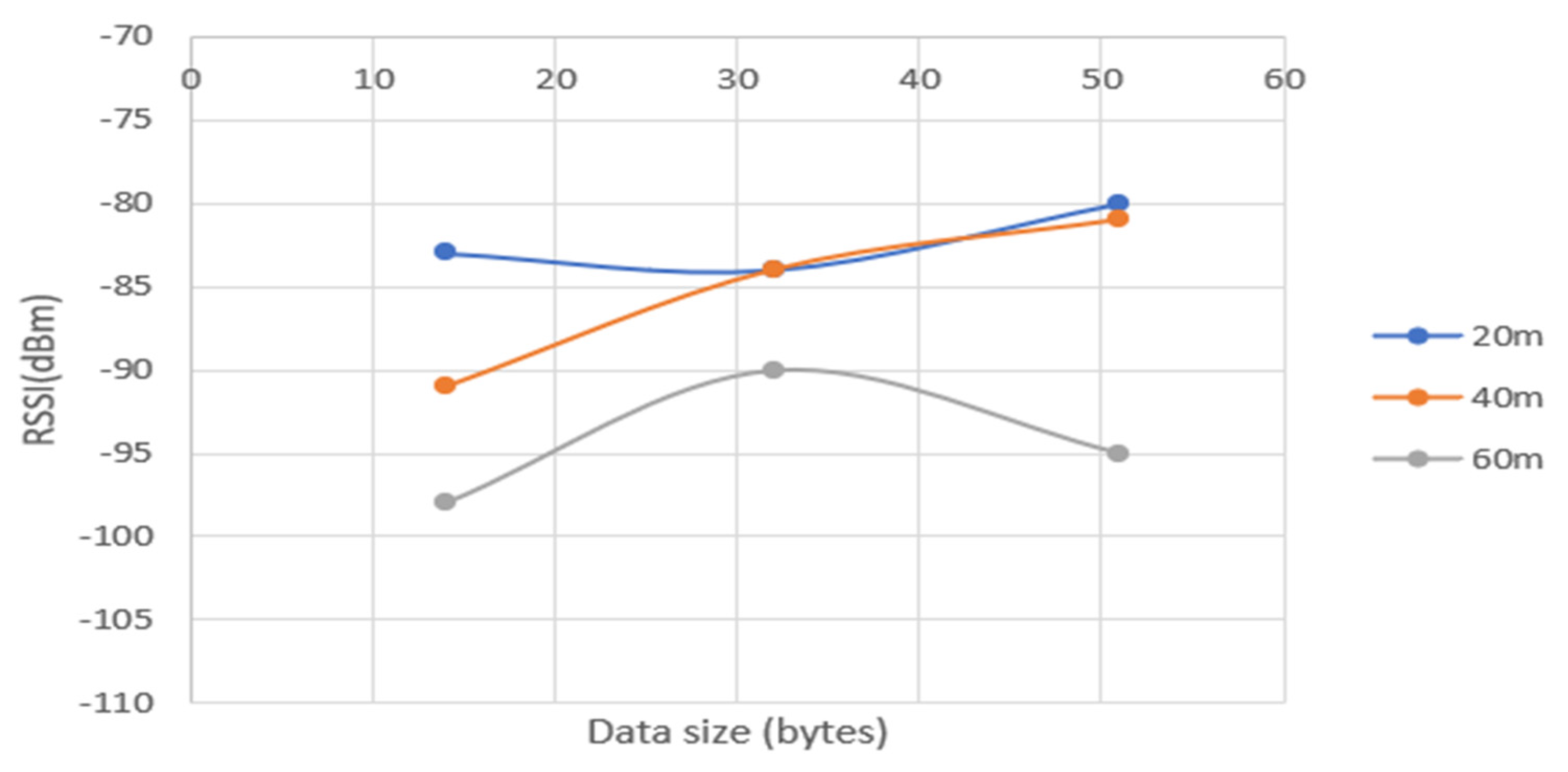
Figure 22.
Send/Receive packets different SF and distances.
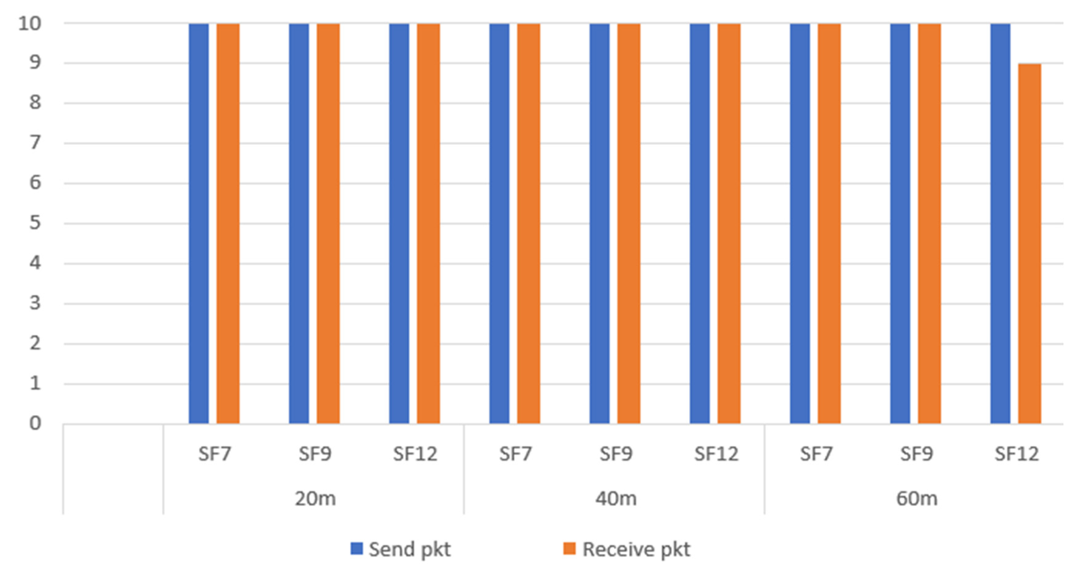
Figure 23.
Influence of the payload size (for the three SFs) on ToA and on the RSSI (with vegetation). ToA according to RSSI for different SF, data size and including vegetation.
Figure 23.
Influence of the payload size (for the three SFs) on ToA and on the RSSI (with vegetation). ToA according to RSSI for different SF, data size and including vegetation.
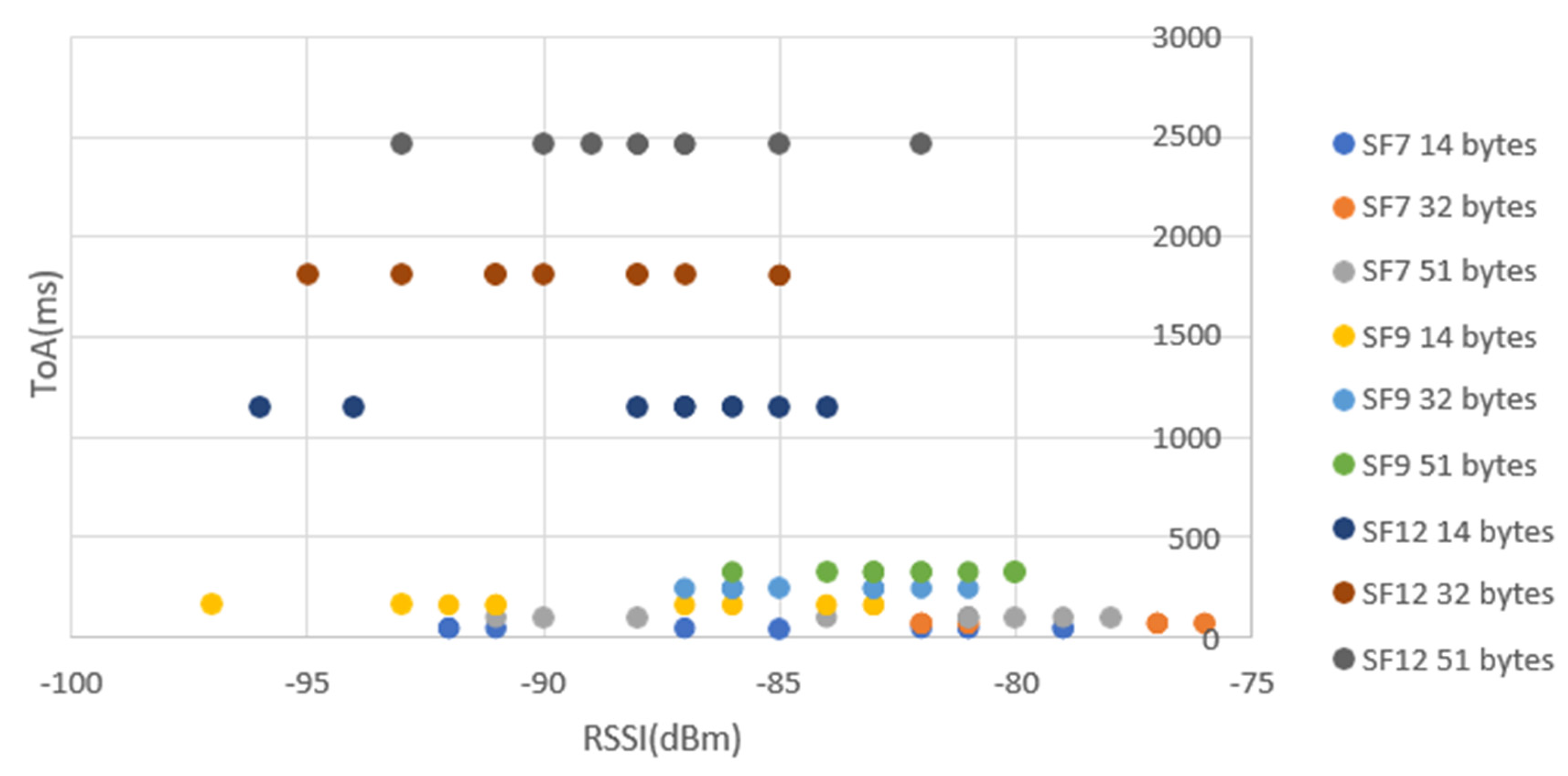
Figure 24.
Influence of the payload size (for the three SFs) on ToA and on the RSSI (with building).
Figure 24.
Influence of the payload size (for the three SFs) on ToA and on the RSSI (with building).
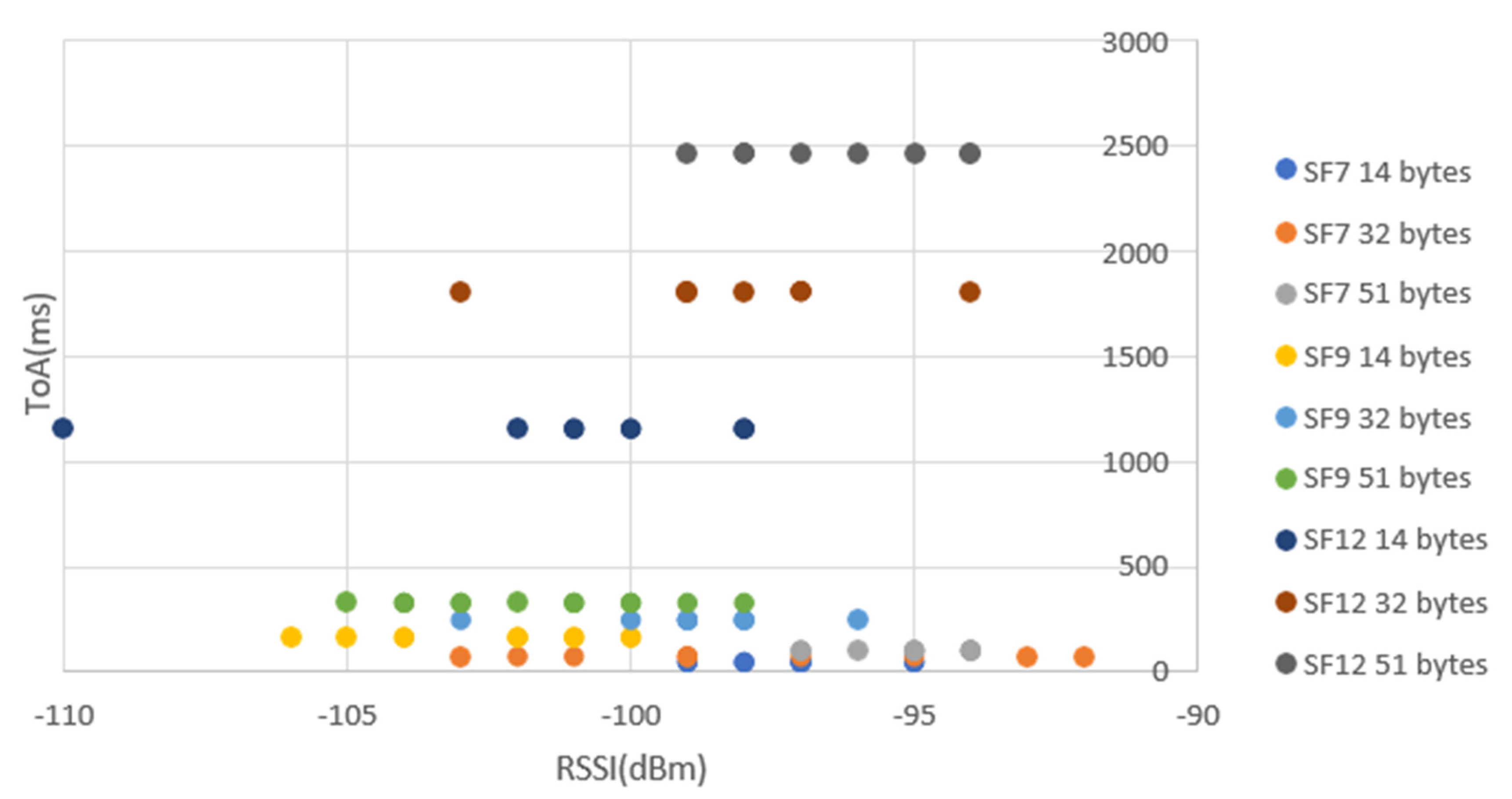
Figure 25.
ToA according to SFs and data size in NLOS scenario.
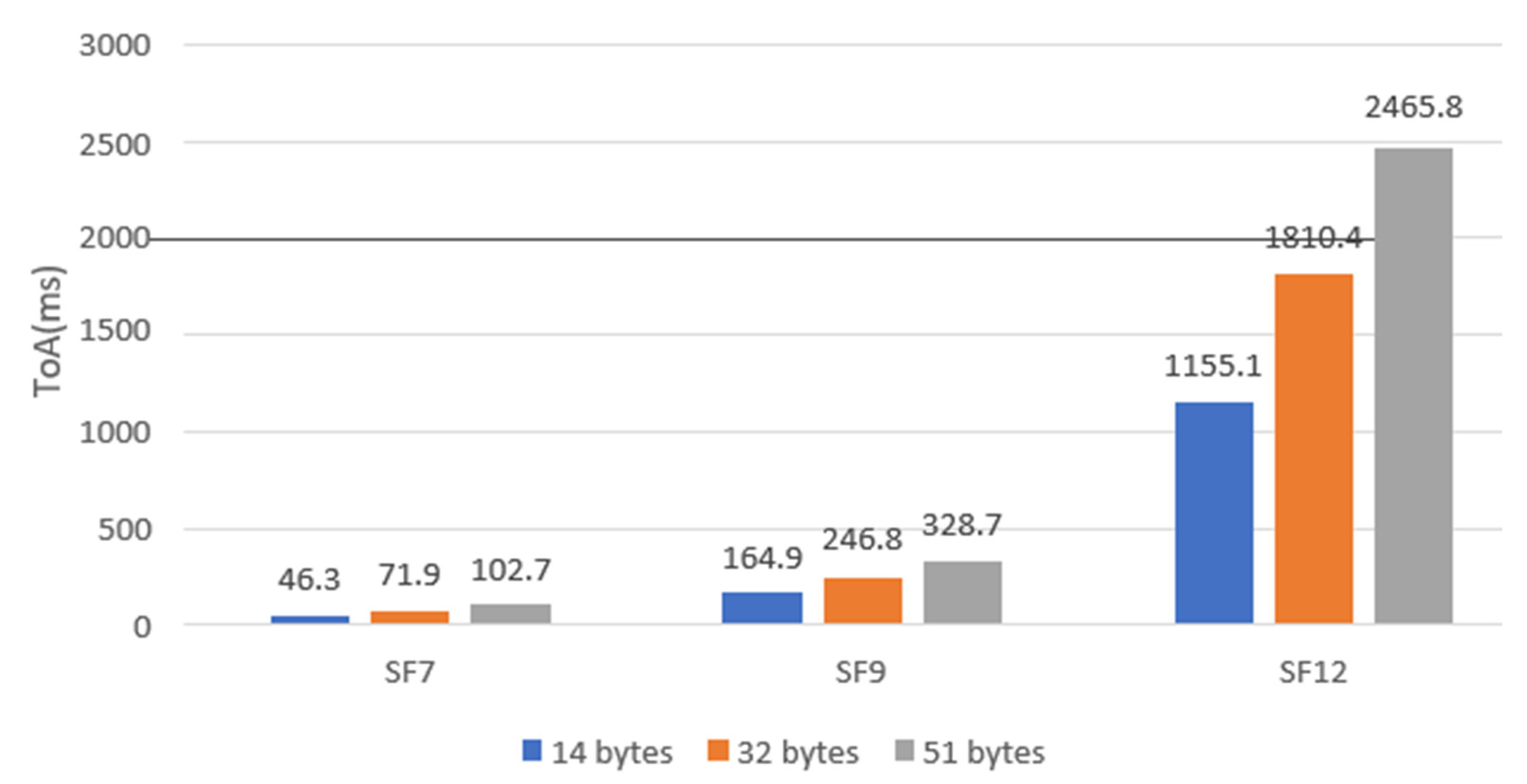
Figure 26.
RSSI according to data size for different SFs, including vegetation.
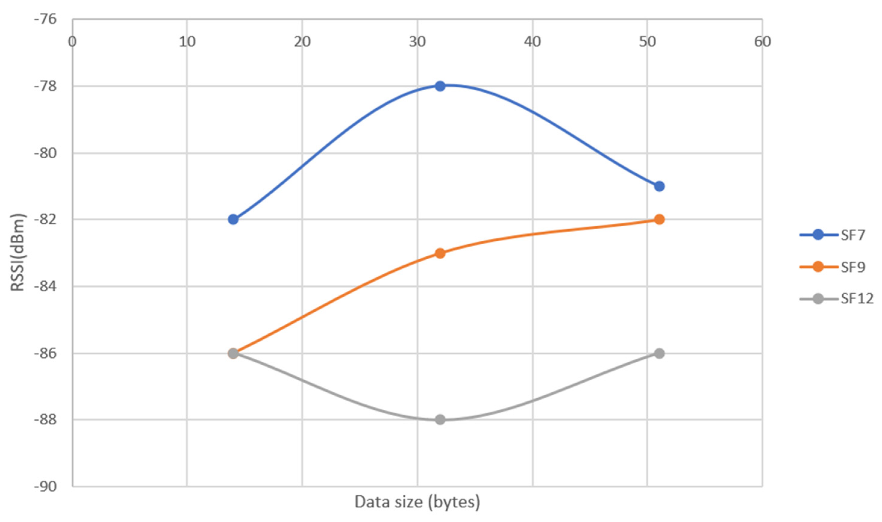
Figure 27.
RSSI according to data size for different SF, including a concrete wall of a building.
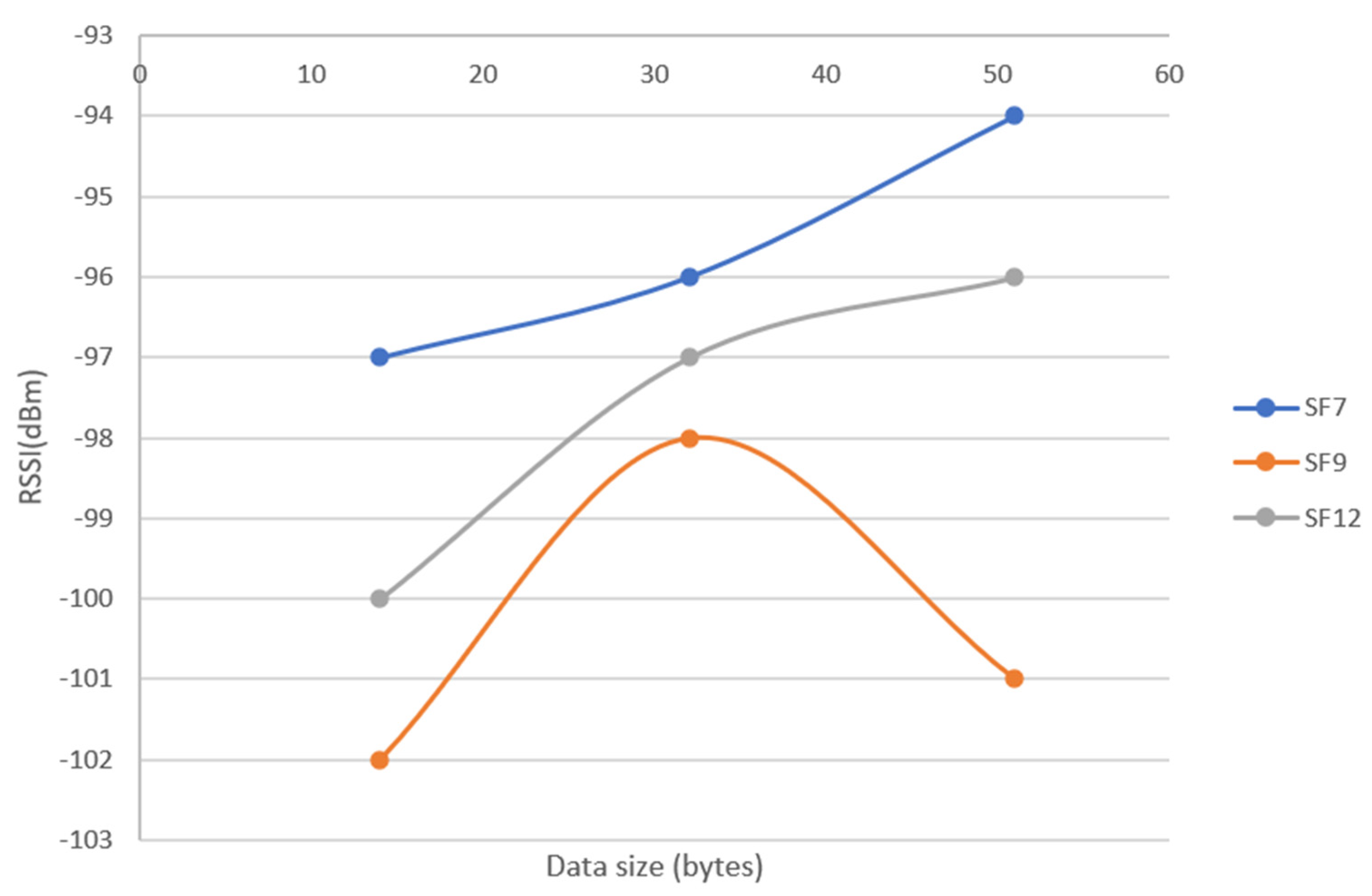
Figure 28.
Send/Receive packets different SF and distances, including vegetation.
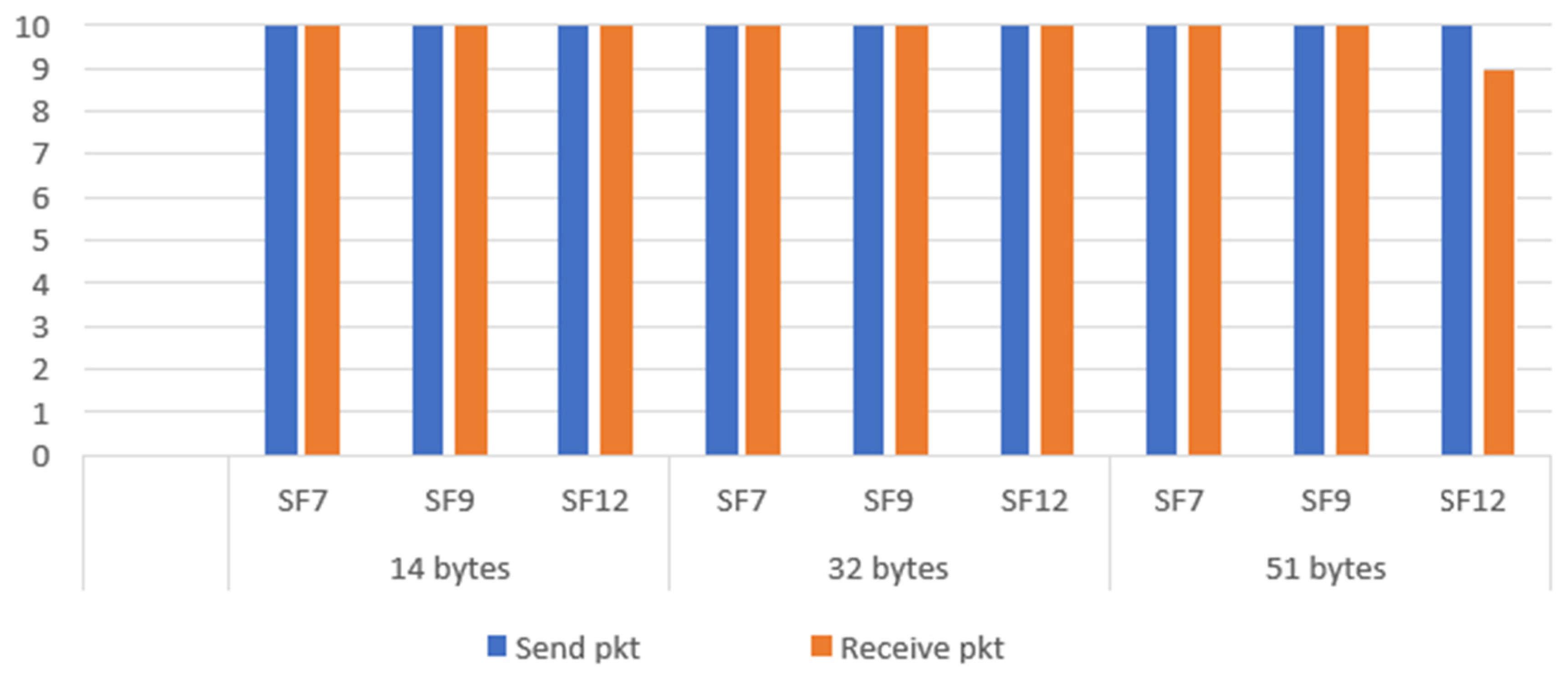
Figure 29.
Send/Receive packets different SF and distances, including a concrete wall of a building.
Figure 29.
Send/Receive packets different SF and distances, including a concrete wall of a building.
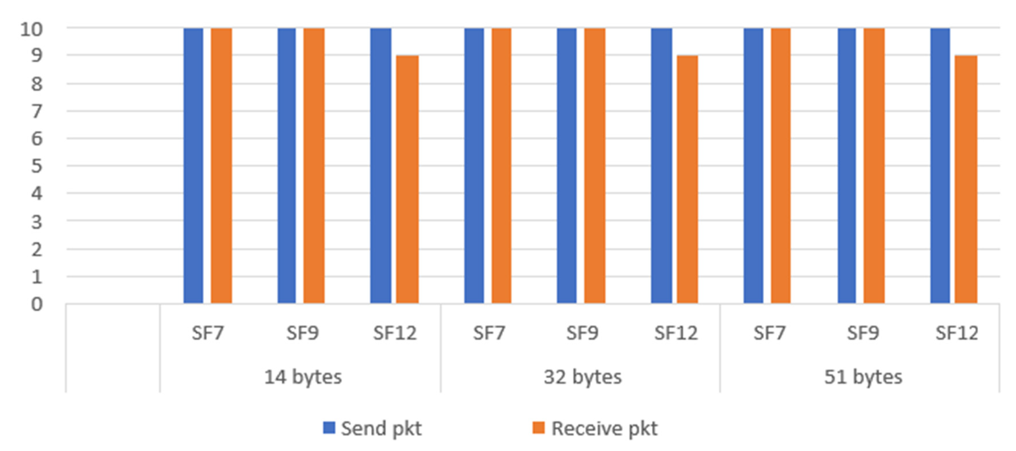

Table 1.
Relationship between SF, Rs, chips per chirp and Rc, for a 125KHz BW.
| SF | Chips per chirp | ||
| 7 | 976,56 | 128 | 125000 |
| 8 | 488,28 | 256 | 125000 |
| 9 | 244,14 | 512 | 125000 |
| 10 | 122,07 | 1024 | 125000 |
| 11 | 61,04 | 2048 | 125000 |
| 12 | 30,52 | 4096 | 125000 |
Table 2.
SIR Margin for all combinations of SF (for the desired and interferer user) [18].
Table 2.
SIR Margin for all combinations of SF (for the desired and interferer user) [18].
| Interferer SF | 7 | 8 | 9 | 10 | 11 | 12 |
| Desired SF | ||||||
| 7 | -6 | 16 | 18 | 19 | 19 | 20 |
| 8 | 24 | -6 | 20 | 22 | 22 | 22 |
| 9 | 27 | 27 | -6 | 23 | 25 | 25 |
| 10 | 30 | 30 | 30 | -6 | 26 | 28 |
| 11 | 33 | 33 | 33 | 33 | -6 | 29 |
| 12 | 36 | 36 | 36 | 36 | 36 | -6 |
Table 3.
RF Sensitivity (dBm) of the SX1276 considering SF and BW [24].
Table 3.
RF Sensitivity (dBm) of the SX1276 considering SF and BW [24].
| SF | 7 | 8 | 9 | 10 | 11 | 12 |
| BW | ||||||
| 125 kHz | −123 | −126 | −129 | −132 | −133 | −136 |
| 250 kHz | −120 | −123 | −125 | −128 | −130 | −133 |
| 500 kHz | −116 | −119 | −122 | −125 | −128 | −130 |
Table 4.
LOS scenario settings.
| SF | 7,9,12 |
| Distance | 20, 40, 60 m |
| Emitting Power | 8 dBm |
| Frequency | 868.2 MHz |
| Data size | 14, 32, 51 bytes |
| Code Rate | 4/5 |
| Bandwidth | 125 kHz |
| Duty Cycle | 1% |
| Time between messages | 1 s |
Table 5.
NLOS scenario settings.
| SF | 7,9,12 |
| Distance | 60 m |
| Emitting Power | 8 dBm |
| Frequency | 868.2 MHz |
| Data size | 14, 32, 51 bytes |
| Code Rate | 4/5 |
| Bandwidth | 125 kHz |
| Duty Cycle | 1% |
| Time between messages | 1 s |
Disclaimer/Publisher’s Note: The statements, opinions and data contained in all publications are solely those of the individual author(s) and contributor(s) and not of MDPI and/or the editor(s). MDPI and/or the editor(s) disclaim responsibility for any injury to people or property resulting from any ideas, methods, instructions or products referred to in the content. |
© 2024 by the authors. Licensee MDPI, Basel, Switzerland. This article is an open access article distributed under the terms and conditions of the Creative Commons Attribution (CC BY) license (http://creativecommons.org/licenses/by/4.0/).
Copyright: This open access article is published under a Creative Commons CC BY 4.0 license, which permit the free download, distribution, and reuse, provided that the author and preprint are cited in any reuse.


