
Submitted:
29 May 2024
Posted:
30 May 2024
You are already at the latest version
Abstract
As technology advances, the field of electrical and computer engineering continuously demands the introduction of innovative new tools and methodologies to facilitate effective learning and comprehension of fundamental concepts. This research addresses an identified gap in technology-augmented education capabilities and researches the integration of Virtual Reality (VR) technology with real-time electronic circuit simulation to enable and enhance the visualization of non-observable concepts such as voltage distribution and current flow within these circuits. In this paper, we describe the development of our immersive educational platform, which makes understanding these abstract concepts intuitive and engaging. This research also involved the design and development of a VR-based circuit simulation environment. By leveraging VR’s immersive capabilities, our system enables users to physically interact with electronic components, observe the flow of electrical signals, and manipulate circuit parameters in real-time. Through this immersive experience, learners can gain a deeper understanding of fundamental electronic principles, transcending the limitations of traditional two-dimensional diagrams and equations. Furthermore, this research focuses on the implementation of advanced and novel visualization techniques within the VR environment for non-observable electrical and electromagnetic properties, providing users with a clearer and more intuitive understanding of electrical circuit concepts. Examples include color-coded pathways for current flow and dynamic voltage gradient visualization. Additionally, real-time data representation and graphical overlays are researched and integrated to offer users insights into the dynamic behavior of circuits, allowing for better analysis and troubleshooting.
Keywords:
virtual reality
; education
; circuit simulation
; visualization
; immersion
1. Introduction
With the ever-expanding world of technology, innovative new ways of utilizing this technology in critical areas such as education emerge. Within electrical engineering, simulation software such as MultiSim and Spice has been used to teach students how to create circuit schematics and simulate these circuits to find various voltages and currents. These tools, along with building and testing circuits in person, give new students insight into the fundamental aspects of circuitry. However, events like COVID-19 and other factors continue to impact students and prevent in-person labs from taking place. Furthermore, whereas in-person labs teach students how to assemble circuits and troubleshoot them, they often do little to deepen their understanding of the core principles governing these circuits, primarily because these effects and principles are non-observable. This prompted the research and development of solutions to virtualize these in-person labs through the use of virtual reality (VR) technology. VR allows for computer-generated scenes and objects to be rendered with the use of a headset, allowing the user to immerse themselves in these computer-generated environments and for the user to interact with them through a controller system or hands-free interactions. VR technology presents a unique new ability to visualize the non-visible – and this traditionally non-observable – fundamentals in electrical and electronics engineering.
1.1. Related Work
VR has gained attention as a tool to promote learning, especially in remote labs or home learning for electrical labs. Various methods ranging from fully immersive VR with head-mounted devices to augmented reality applications and web-based interfaces have been researched and attempted.
For instance, the creators of the Three-Dimensional Virtual Simulation Experiment Platform, [1], utilized the Unity 3D engine [2] and Autodesk’s 3ds Max to develop a realistic lab environment that imitates integrated circuit manufacturing and testing. Students interacted with this virtual environment via a web-based interface, conducted experiments, and received feedback on their performance. While the virtual environment was not as immersive as a head-mounted display (HMD), students’ grades showed improvement after completing the virtual experiments. However, some students encountered issues with network connectivity and long loading times.
Cao et al. [3] introduced a guided virtual reality education simulation that allows primary school students to learn basic analog circuit concepts. Basic components of switches and light bulbs were displayed with 3D models, and a simplified visualization of current was shown through an overlay above the wires. Utilizing realistic circuits rather than simplified or abstract representations allows the younger students to grasp the different topics, with 9% of students showing improvement from a pre-experiment quiz. Jiang et al. [4] developed a similar application with the ability to allow multiple users to experiment on the same circuit. Like in [3], the circuitry utilized simplified blocks to allow for easier configuration of simple analog circuits.
Khairudin et al. [5] took a similar approach with an interactive virtual laboratory that focused on visualizing and simulating logic circuits in real-time. Circuits were shown as 2D images, and the circuit’s inputs were controlled by switches that could be toggled, allowing students to try different combinations.
In [6], the authors describe their approach to implementing an application that can read a resistor network topology and generate a netlist. Then, using LTspice, the properties of the individual components are outputted to the Unity 3D engine’s terminal.
The authors of [7] used augmented reality (AR) to create an immersive simulator. AR allows users to see the surrounding space and overlays virtual models and UI to create a mixed-reality experience. Using tokens to identify different circuit components and a simulator back end, users could change circuit parameters and see real-time changes in graphs depicting different output voltages and power. This approach focused on being a low-cost solution, with the platform being an Android mobile device or tablet, allowing for easy-to-use functionality.
Zamojshi et al. in [8] used a different approach to teach students about electronics and telecommunications. They created a virtual reality "escape room" called Ohm VR, where students could learn through a series of puzzles. The interactive modules were placed on the walls of the virtual room, allowing students to input answers on keypads. After using the application, students’ scores on a quiz related to the topics improved, and the improvement remained even two weeks later when the survey was given again. This proves that VR education applications can be effective tools in helping students learn STEM-related concepts.
While these applications clearly show the benefits of using VR in electrical education, there are still gaps within the current learning space. For example, the current approaches do not fully utilize VR’s capability to visualize elements such as current and voltage, which are invisible to the human eye and can be hard to visualize. Additionally, students face difficulties with using breadboards to create and debug circuits. To address these issues, a VR-based approach that simplifies the creation and manipulation of circuit elements while taking full advantage of VR’s visualization capabilities is needed.
1.2. Scope and Contributions
This paper contributes to the existing body of knowledge by implementing a visualization system that allows students to see voltage and current interaction within different circuit topologies. Additionally, realistic interactions between circuit elements and a breadboard were modeled by leveraging Unity’s physics engine. This allows students to design and build their circuits in a realistic setting and provides an opportunity to learn and strengthen good breadboarding practices. For this work, we researched and implemented a novel real-time integration with a circuit simulation framework. Additionally, in this work, we established the foundations for a modular and highly extensible framework for electrical circuit simulations that supports both analog and digital components, which is successfully demonstrated by utilizing a variety of analog components, such as resistors, switches, capacitors, and LEDs, as well as with several different digital Integrated Circuits (ICs).
2. Materials and Methods
In this section, we are showing our process for implementing this VR platform for electrical engineering education. We will also examine the utilized development resources and explain how different elements were designed, implemented, and validated within the Unity 3D engine environment.
2.1. Devices Used for Development
Throughout this project we utilized a variety of different VR systems. Out of those, our efforts focused on two different systems: the HTC Vive and the Meta Quest 2.
The HTC Vive is a tethered VR system, meaning that an external computer system is needed to run the application for the headset. The headset is connected to that computer via an HDMI cable to receive the visual data generated from an application. The HTC Vive uses beacons installed in the environment, called Lighthouse, which enables it to track the VR headset user within the "play space." Through this system the user is free to move around within the environment and be more immersed in the virtual scenery. The HTC Vive has a few drawbacks, however, that were discovered in connection with this project. First, while the HTC Vive allows movement in the play space, that mobility is limited by the lighthouse beacons and their visibility within the area. If the beacons lose track of the user’s position, it results in unexpected and undesirable loss of immersion for the user. Thus, in order to fully utilize this tracking, an open space is needed. This limits the space that users could use when using our application. Additionally, the tethered nature of the system results in further degradation in the level of immersion since the user needs to be somewhat aware of the cable’s position to avoid falls or stumbles. It is also limiting to the user’s movements. Finally, having to be connected to a computer at all times limits where and how students can use this application.
The Mate Quest 2, on the other hand, does not share these limitations. It is a stand-alone system, meaning that all of the computing needed to run its applications resides within the headset. Along with the built-in tracking cameras that identify and track the user’s position, this allows users to take the Quest 2 anywhere and use applications in virtually any setting. However, due to the compact form factor, this somewhat limits the available computational capabilities and the visual fidelity of the experience. The Quest 2, however, is also capable of using its tracking cameras to track the user’s hands and fingers to allow for hands-free control. This makes the Meta Quest 2 a very compelling choice for a virtual laboratory experience, such as the one demonstrated in this paper.
2.2. Software Used for Development
This research project used various software applications to aid in its development. The main applications were Unity [2], Spice# [9], and Fusion360 [10].
2.2.1. Unity
Unity is a 3D engine and development framework used to develop various 2D, 3D, virtual reality, and augmented reality applications. With a built-in physics engine, gravity and collisions can be simulated between virtual objects and other elements referred to as GameObjects in Unity, allowing for highly dynamic and interactive scenes to be created. Additionally, Unity supports a rendering and material engine that allows for control over shaders and lighting generation. Finally, through an extensive library of software packages, there is support for VR development out of the box with the use of OpenXR and the XRI toolkit. Within Unity, there are multiple terms used to describe different elements used in the creation of an application: GameObjects, as indicated earlier, are any object that is within the workspace of Unity. This can be a cube, a complex mesh model, or an empty object. A GameObject needs multiple Components to define different aspects of itself, like what color it is, whether it is affected by the Physics Engine and whether there are any scripts associated with that GameObject.
Each of these GameObjects is its own entity but can be grouped together to create families of GameObjects. These families can then be saved as Prefabs or templates that can be easily used multiple times within a scene. For developers, editing the root Prefab will change all instances of that specific Prefab, while during runtime, each prefab will be independently interacted with and changed based on user inputs.
2.2.2. Spice#
Spice# is a C# port of Spice [11], which is a popular circuit simulation tool. Since Unity uses C# for its scripting language, Spice# could be used directly within the application. This allows for all of the simulations to be run directly on the headset without the need for an outside connection. Simulation is straightforward: different elements are added to the simulator circuit, each with its own parameter sets like resistance, voltage, and connection points. Then, the simulator is run and outputs a variety of properties, such as the model voltages, of the circuit to be generated. Different circuit topologies were tested through the creation of basic example scripts that were first run outside of the development environment and later also used for the integration testing of Spice# into Unity.
2.2.3. Fusion360
Fusion360 is computer-assisted design software for creating 3D models. This program was used to create and modify existing models of the electrical elements [12,13,14,15].
As discussed later in this section, in Unity, templates called Prefabs can be created out of multiple GameObjects. This Prefab can be initialized multiple times within a scene with default parameters. In order to create said Prefabs, the original models of the circuit elements needed to be edited to be in separate parts. For example, for all of the analog elements, the main body of the element needed to be separated from the leads of the element. This allows for different components and scripts to be applied to the body that is being directly affected.
2.3. Virtual Reality Device Rig
It is important to accurately translate the user’s real-world position into the virtual space. By utilizing OpenXR and Unity’s libraries, a virtual reality device rig was imported into the workspace. This allows Unity to track the movement of the headset and controllers and read button inputs. As seen in the left image of Figure 1, the controller is modeled so the user can see when they are manipulating objects. The rig comes with three types of interactor elements: Poke, Direct, and Ray. These interactors control how the user can manipulate the GameObjects in the scene. The "Poke" interactor allows for the UI to be "poked", for example to mimic pressing buttons or adjusting sliders. The "Direct" interactor allows the user to virtually grab a GameObject, pick it up, and turn it around. Finally, the "Ray" interactor extends a ray from the controller model in the direction it is pointing at, and allows for GameObjects and UI to be interacted with from a distance.
With the Quest 2’s ability to track the users’ hands, the rig we implemented within our virtual world was expanded with the XRhands package that allows Unity to access the hand tracking data of the map virtual hand models, seen in the right image of Figure 1, allowing for users to leverage far more intuitive manipulation gestures. This also has the Poke, Direct, and Ray interactors, allowing the users to seamlessly pick up GameObjects and interact with UI menu buttons and sliders.
2.4. Development of Circuit Elements
Within Unity, each circuit element needed to be created with custom scripts that connected the GameObjects with the Spice# simulator.
The breadboard, for example, is a main component with all of the connection points of a real-life breadboard being modeled, as shown in Figure 2. The top plate of the breadboard has a ’mesh collider’ attached to it. This allows for the mesh of the model to be used to calculate collision points. This means that elements or their leads, such as the legs of an IC or the terminals of a resistor, can not go through this top plate except at the locations of each of the holes. Each of the brown squares represents a common connection point for the inner columns, as well as the top and bottom rows. Each of these contact strips has a script that is used in the circuit calculations to obtain the model voltage at that point.
The leads of the elements are attached to the main body of the element as children’s GameObjects within the Prefab. These leads have box colliders and ridge body components attached to them. These components allow for this GameObject to interface with Unity’s Physics engine. RigidBody components cause the leads to be treated like solid objects. They will collide with other GameObjects; the box collider component will allow the system to detect these collisions and trigger scripts based on collision entrance or exit.
Other electronic elements, including voltage sources, resistors, capacitors, switches, LEDs, and wires, were created to populate this breadboard. All of these elements needed to be either modeled from scratch or by significantly modifying existing models in order to facilitate their integration with the circuit simulation, for example by isolating individual elements such as legs and main bodies. These separate parts were then used to create prefabs of the electrical components. As seen in Figure 3, the resistor GameObject is made up of individual parts; this allows for different components and scripts to be attached directly to the part they will interact with. All of the electrical elements have a prefab created so that multiple instances can be spawned to give users the ability to build larger and more complex circuits.
All of the electrical element’s legs needed to interact with the breadboard’s internal contact pads. A RigidBody component and Box Collider component were attached to each of the legs. The RigidBody component allows for the attached GameObject to be affected by Unity’s Physics Engine, allowing for it to experience gravity and collide with other GameObjects with RigidBody components. A script attached to the leg GameObjects interfaces with a physics engine to track connection points on a breadboard. It utilizes two methods: ’OnCollisionEnter’ and ’OnCollisionExit.’ ’OnCollisionEnter’ is triggered when a GameObject with a RigidBody component collides with another GameObject that has a Collider component, and vice versa. The ’collision’ parameter provides details about the collision, and the script filters events to focus only on collisions involving GameObjects tagged as ’Wire’ or ’Wire_connected.’ These tags are assigned to the connection points on the breadboard.
When a collision with one of these tagged wires occurs, the script updates the GameObject’s tag to ’Wire_connected’ and increments a counter using the ’contact’ parameter within the ’Wire_info.’ This is tracked and implemented on a per-lead basis. For example, for a component with two legs, such as a resistor, depending on whether the script is associated with "Lead 1" or "Lead 2" it updates the connection parameters ’connection_A’ and ’connection_B’ within the parent script (such as ’Resistor_info’) with the name of the collider it interacted with. This approach allows for flexible tracking and updating of connection points for various components on a breadboard.
For the main body, scripts store and manipulate the element’s information, like voltage over the element, and specific attributes, like the resistance value that is associated with a resistor element. This will be discussed further in Section 2.6, describing for example how these scripts are used to retrieve circuit information for the simulator and how the results of the simulation are used to update each element.
To demonstrate the application’s ability to simulate digital logic, different digital logic integrated circuit (IC) packages were created. These ICs were chosen to represent both basic and complex digital components and include the 74ls08, which is a Quad AND Gate IC, and the 74ls283, which represents a 4-bit Full Adder with Fast Carry.
For simulating these ICs we evaluated both an approach utilizing a transistor-level simulation using the Spice# simulator framework, as well as a logic-driven circuit abstraction approach. From these experiments, we found that the transistor-level calculations were too slow, with updates resulting in a delay of approximately 200ms that in turn disrupted Unity’s frame generation loop for the VR headset. This caused the last image frame to remain static, and as the user moved their head, black spaces appeared in the unfilled regions, breaking the immersive experience. These issues could be resolved with the IC circuit abstraction approach, which proved to be both highly efficient and sufficiently accurate. In this approach, rather than low-level transistor simulations, the circuitry of the ICs was abstracted, interfacing with the rest of the virtual circuit through their input and output pins. The contact scripts for these digital ICs are similar to those for analog elements but handle more connection points (14 and 16 pins).
For the 74ls08 script, two input fields are used: ’connections’ and ’logic_levels’, which represent the physical leg connections and their respective logic levels. In the Update method, an ’outputs’ dictionary is initialized to store the connection points and logic levels. The variables ’high’ and ’low’ are set from the voltage levels at the VCC and GND pins. The script then loops through all connections to update their logic values. Using logical operations, the inputs for each AND gate are processed, and the results are assigned to the corresponding output pins. The voltage node levels are updated with these logic levels, and the updated outputs are stored in the ’outputs’ dictionary and returned. The implementation for the 74ls283 is similar, but it performs bit-wise addition with carry bits to implement the 4-bit adder.
By implementing and evaluating these two ICs we could demonstrate that this abstraction allows for efficient simulation of digital logic components in a VR environment without the performance issues associated with low-level transistor simulations.
2.5. User Interfaces
For all the various GameObjects that represent electrical components, we also implemented different menus to allow users to control various aspects of the component instance and the overall simulator. Each of these electrical components, with the exception of simple wires, has a UI representation that indicates the voltage over and current through that specific component. Also, this UI has a control slider for its electrical characteristics. For example, the resistor’s UI has a slider that allows the resistance value of that resistor to be changed in the simulation. Other menus allow users to spawn in additional instances of the electrical components and navigate to different scenes that demonstrate various capabilities of this VR educational application.
2.6. Simulation Implementation
For realizing the circuit simulation backend we researched lightweight computational frameworks that could directly be integrated on the Quest 2’s hardware. We selected an open-source project called Spice# for this purpose, which is a C# port of SPICE, and then designed an interface between it and the rest of the VR application. This allowed for a direct Spice# interaction between the virtual world and the circuit representation, through a variety of Unity scripts. This also allows updates to the virtualized circuit to trigger immediate recalculations via Spice#, and for its results to be immediately realized within the visualization of the circuit parameters. Using Spice# as the backend circuit simulator, each electrical component is added to the simulation netlist to build the circuit topology. This process is managed by the application’s main script, which parses all active electrical components to extract the necessary values for the simulator and updates relevant fields once the simulation calculates the circuit’s nodal voltages. When the value of an electrical component is updated, the "Create_net_list.cs" script is triggered, initiating a rerun of the simulation. The simulator first clears the previous circuit and creates two arrays: one for all active components and a second array for breadboard wires with connections. Each electrical component in the array is assigned a unique name with an incrementing number tag. The script then gathers relevant values from these components to create netlist elements corresponding to their respective data types. For instance, when adding a resistor to the simulation, a temporary variable is created using the Resistor class, passing the resistor’s name, connection points, and resistance value into the constructor. This variable is subsequently added to the simulator’s netlist.
After all electrical components have been added to the simulator, the output streams are mapped to the active node wires. The simulator then calculates the node voltages and updates the voltage_node field for each node wire. Following the simulation, each circuit component is updated accordingly. Analog components use these node voltages to compute the current through each component. For digital logic, additional steps involve creating voltage sources to act as drivers for the IC’s output pins. These new voltage sources are added to the circuit’s netlist, and the simulation is rerun to update any components connected to the output pins. A flowchart illustrating this process is shown in Figure 4.
2.7. Development of Visualization Components
2.8. Universal Visual Pipeline
Unity’s Universal Render Pipeline (URP) is a rendering pipeline that is designed to optimize real-time rendering performance. It is a lightweight pipeline suitable for projects that target mobile platforms like stand-alone VR applications. URP offers different configuration options to provide a balance between performance and visual quality. The two main features of URP are lightweight materials, shaders, and shader graphs. These features help Quest 2 to display the virtual environment and circuitry components with different and changing colors while not affecting performance. Additionally, the shader graph enables the creation of custom shaders through a visual interface.
A custom shader was developed using Shader Graph to create an animated line that represents the current flowing through electrical elements. When creating a shader, external variables associated with the shader can be used to affect the shader’s operation. In Figure 5, multiple nodes were connected to create a moving dotted line. The first input is ’Current,’ which represents the current passing through the parent electrical element. This value is then multiplied by system time to create a vector that increases based on the current. The ’Tiling And Offset’ and ’Fraction’ nodes are used to create a scrolling texture that is driven by the time and current-based vector. This scrolling texture is then passed through an ’Ellipse’ node to create a dotted masked texture. Finally, the ’Vertex’ and ’Fragment’ nodes enable the texture to be rendered by the pipeline when assigned as a material component. The finished shader can be seen in Figure 6 as the yellow dotted lines.
2.9. Line Render
Renders are a unique feature in Unity that allows the developer to input a set of points in 3D space and create a straight line connecting those points. The developer can adjust the parameters of this component, such as the width of the line, light generation, and texture modes, among others. To create the illusion of motion, a custom texture was applied to the "Material" field, and a yellow color was chosen to simulate the current. This makes the line appear like a series of dots moving along the path of the line.
When these line renders are visible, it’s called the "Current View Mode." To achieve this mode, the GameObjects need to be slightly translucent. During implementation, this can be accomplished by using the "Transparent_view" script, which we can apply to the affected parent GameObject. We then assign the children GameObjects required to be translucent to the "renderers" list, while GameObjects that are required to be invisible are assigned to the "hidden_renderers" list.
If enabled, the script will parse both lists and make the GameObjects either translucent by changing their alpha value or invisible by disabling their renderer altogether. If this feature is disabled, the script will reset all the GameObjects in the lists to their normal visual states.
2.10. Color Changing
As mentioned earlier, GameObjects that have a mesh model that contains a component responsible for the color of that mesh. This component can be modified by scripts using Unity’s API. In this case, the "Color_change_on_voltage" script is used to change the color of the attached GameObject based on its voltage. When this script is initialized, it stores the GameObject’s ’Renderer’ to revert the color of the GameObject if the script is disabled.
When the script is enabled, it assigns the component’s current voltage to ’voltageOver’. Based on the value of this variable, the script interpolates between the below-threshold color and the middle color or between the middle color and the above-threshold color. The resulting interpolated color is then applied to the GameObject’s ’Renderer,’ updating the color for the next frame.
3. Results and Discussion
The outcome of this research is a functional Virtual Reality circuit editor and simulator that visualizes non-observable electrical characteristics such as voltage and current. Users can navigate the VR environment using the Quest 2 headset and interact with electrical components and menus using either the controllers or hand tracking. The simulator includes various circuit elements, enabling users to construct, for example, resistive and RC circuits. Users can utilize switches and LEDs to control inputs and outputs. Additionally, two modeled digital ICs provide the capability to experiment with digital logic, and demonstrate the flexibility and extensibility of the implemented platform.
3.1. Visualization of Current Direction and Magnitude
As described in the preceding chapter, we were able to effectively illustrate the flow of current through the use of Unity’s Line Render feature, which was customized with a texture to enhance its visual impact. The resulting effect convincingly conveys the sensation of current movement, as evidenced in the accompanying figure. By employing this visualization method, students are now equipped with a clear understanding of the direction and strength of current in electrical circuits, eliminating any confusion or uncertainty.
3.2. Visualization of Voltage Drops
Similarly to current, the voltage across circuit elements and its relation to Kirchhoff’s Voltage Law (KVL) allows users to observe the distribution of voltage across a resistive network. Paired with the voltage displayed on each element’s UI, this feature enables comprehensive circuit analysis. Students can verify their homework, for example, by easily replicating their circuits in the simulator, adjusting parameters, and observing the exact voltage and current outputs.
In Figure 7, both branch currents and element voltages are shown. All resistors are configured to 1k Ohm. The "red" resistor exhibits a 5-volt drop, indicating the highest voltage, followed by the "orange" resistor with a 3-volt drop. The middle "yellow" resistor shows a 2-volt drop, while the remaining two "green" resistors each have a 1-volt drop. This example helps students understand how voltage and current behave in series-parallel resistor networks.
3.3. Digital Logic Implementation
Two digital ICs were developed to interface with the Spice# simulator. These ICs can be controlled by wires directly connected to power and ground sources or through switches. Their outputs can power LEDs to show the output states. Both the 74ls08 and the 74ls283 can be seen in Figure 8. The implementation of digital circuits expands the circuits that students can experiment with.
3.4. Real-Time Simulation Updates
The simulator’s visualization elements are updated in real-time as soon as a user modifies a parameter, keeping all voltage and current values up-to-date. The application was designed to avoid any bottlenecking and ensure smooth performance. Unity’s pipeline operates in a linear fashion, starting with physics calculations and then moving to game logic. Once all scripts finish executing in the game logic stage, Unity proceeds to the rendering stage to generate a new frame. Hence, it is critically important to avoid any delays or prolonged computations during any of these stages in order to ensure high frames rates, which in turn is vital to avoid nausea and disorientation in the VR user.
4. Discussion
Our new electrical engineering VR educational application offers users an immersive experience in constructing and testing circuits. It can be used as a valuable supplement to students’ education, helping them enhance their understanding of basic concepts. The current framework prototype clearly demonstrates these capabilities. It also shows that it can easily be expanded to accommodate more complex analog and digital circuits and components.
Using the simulator is also highly intuitive. Users can launch the application from the Quest 2 menu and will be greeted with a default scene featuring a voltage divider on the breadboard. This will allow newcomers to familiarize themselves with the controls and observe the simulator in action. They can adjust resistance levels using controllers or hand gestures and observe changes in current and voltage. Enabling "Current Mode" or "Voltage Mode" provides users with advanced visuals of current and voltage. Users can choose to progress to various pre-made scenes from this starting scene, such as a switch and LED setup or a pre-made digital logic circuit. Selecting "new scene" loads an empty breadboard, allowing users to place electrical elements in any configuration to build their own circuits.
During the development of this research, several challenges has to be overcome. Our team needed to develop a new approach for digital logic simulation that is both accurate and lightweight. The results was a bridging layer that is highly scalable to more advanced ICs, yet retains the ability to accurately and rapidly compute results that directly interface with the circuit simulation. Throughout the process, we frequently conducted performance evaluations and user experience testing in order to ensure stable and high frame rates, and the lack of any disorienting side effects from using the VR environment. This was especially important for the Meta Quest 2, which uses an onboard processor for all the application’s calculations and visualizations. The source code, along with our media files, will be available upon request for further exploration upon the completion of our ongoing research for it.
5. Conclusion
In this research project, we have developed an innovative VR circuit simulator with advanced visualization capabilities for fundamental electrical concepts. The simulator is designed for the Quest 2 headset and uses the Unity engine, which enables users to interact with different circuit elements and perform various simulations. It includes various viewing modes that allow users to observe current flow direction, magnitude, and voltage drops displayed as gradients across the entire circuit. Users can intuitively interact with the simulator using the Quest 2 controllers or through tracked hand motions.
The creation of this simulator required extensive research and the integration of numerous components. We created all scenes and GameObjects in Unity, with some mesh renders adapted from publicly available 3D models. We developed prefabs from these GameObjects, allowing for the creation of multiple circuit topologies. Each prefab included custom scripts to manage aspects, such as contact points with the breadboard and updating internal variables like voltage and current. The electrical elements and user interfaces were designed to be compatible with both controller-based and hands-free control schemes.
To showcase the application’s capabilities and evaluate the educational user experience, we developed several example scenes, including a basic voltage divider circuit, a resistor ladder circuit, a resistor-capacitor circuit, and a digital logic IC circuit. Custom shaders and scripts were created to visualize current and voltage. A significant challenge was interfacing the electrical elements with the Unity physics engine and using connection points to generate netlists for the Spice# simulator to calculate nodal voltages. We carefully tuned all collider and RigidBody components to minimize unexpected physics effects.
When building the simulation functionality, we also thoroughly investigated the impact on frame generation. This led to optimized scripts that enabled the simulation of digital logic without disrupting the user experience. To our knowledge, no comparable system is available for our students.
Our future research will expand visualization to digital logic, allowing students to "see the gates inside the integrated circuits package." This enhancement would help students connect symbolic representations of digital gates to the physical packages used in real life. Additionally, expanding the simulator’s library to include more electronic components would enable users to simulate and explore a broader range of circuits.
Author Contributions
Conceptualization, Elliott Wolbach; Investigation, Elliott Wolbach; Resources, Michael Hempel; Software, Elliott Wolbach; Supervision, Michael Hempel and Hamid Sharif; Writing – original draft, Elliott Wolbach; Writing – review & editing, Michael Hempel and Hamid Sharif.
Funding
This research received no external funding.
Institutional Review Board Statement
Not applicable.
Informed Consent Statement
Not applicable.
Data Availability Statement
The data presented in this study are available upon request from the corresponding author after completion of the associated research efforts.
Conflicts of Interest
The authors declare no conflicts of interest.
Abbreviations
The following abbreviations are used in this manuscript:
| VR | Virtual Reality |
| AR | Augmented Reality |
| UI | User Interface |
| IC | Integrated Circuit |
References
- Lai, Z.; Cui, Y.; Zhao, T.; Wu, Q. Design of Three-Dimensional Virtual Simulation Experiment Platform for Integrated Circuit Course. Electronics 2022, 11. [Google Scholar] [CrossRef]
- Unity Technologies. Unity, 2005.
- Cao, Q.; Png, B.T.; Cai, Y.; Cen, Y.; Xu, D. Interactive Virtual Reality Game for Online Learning of Science Subject in Primary Schools. 2021 IEEE International Conference on Engineering, Technology & Education (TALE), 2021, pp. 383–389. [CrossRef]
- Jiang, T.; Zhuang, Z. A Multi-person collaborative Simulation System For Circuit Experiment System Base on Virtual Reality. 2021 International Conference on Intelligent Transportation, Big Data & Smart City (ICITBS), 2021, pp. 253–259. [CrossRef]
- M, K.; A.K, T.; W.J, I.; M.N.A, A. Mobile Virtual Reality to Develop a Virtual Laboratorium for the Subject of Digital Engineering. <italic>International Journal of Interactive Mobile Technologies (iJIM)</italic> <bold>2019</bold>, <italic>13</italic>, pp. 80–95. [CrossRef]
- Li, Y.; Shen, Y.; Sukenik, C.; Sanders, B.; Delacruz, P.; Mason, J. Work-in-progress: Rapid development of Advanced Virtual Labs for in-person and online education. <italic>2022 ASEE Annual Conference & Exposition Proceedings</italic> <bold>2022</bold>. [CrossRef]
- Lucas, P.; Vaca, D.; Domínguez, F.; Ochoa, X. Virtual Circuits: An Augmented Reality Circuit Simulator for Engineering Students. 2018 IEEE 18th International Conference on Advanced Learning Technologies (ICALT), 2018, pp. 380–384. [CrossRef]
- Zamojski, P.; Barczyk, N.; Frankowski, M.; Cybulski, A.; Nakonieczny, K.; Makowiec, M.; Igras-Cybulska, M. Ohm VR: solving electronics escape room challenges on the roadmap towards gamified STEAM education. 2023 IEEE Conference on Virtual Reality and 3D User Interfaces Abstracts and Workshops (VRW), 2023, pp. 532–535. [CrossRef]
- Boulanger, S.; Golebiowski, M.; katzb123.; Sodalom, O. Spicesharp.
- 2024.
- .
- Bradley, M. Red LED 5mm, 2012.
- WORKSHOP, M. Breadboard, 2020.
- Salamacha, Z. CD4021B-MIL - CMOS 8-Stage Static Shift Register.
- Šafář, P. THT resistors 1/4 to 5 W (VERTICAL), 2021.
Figure 1.
Left: Controller, Right: Tracked Hand Control.
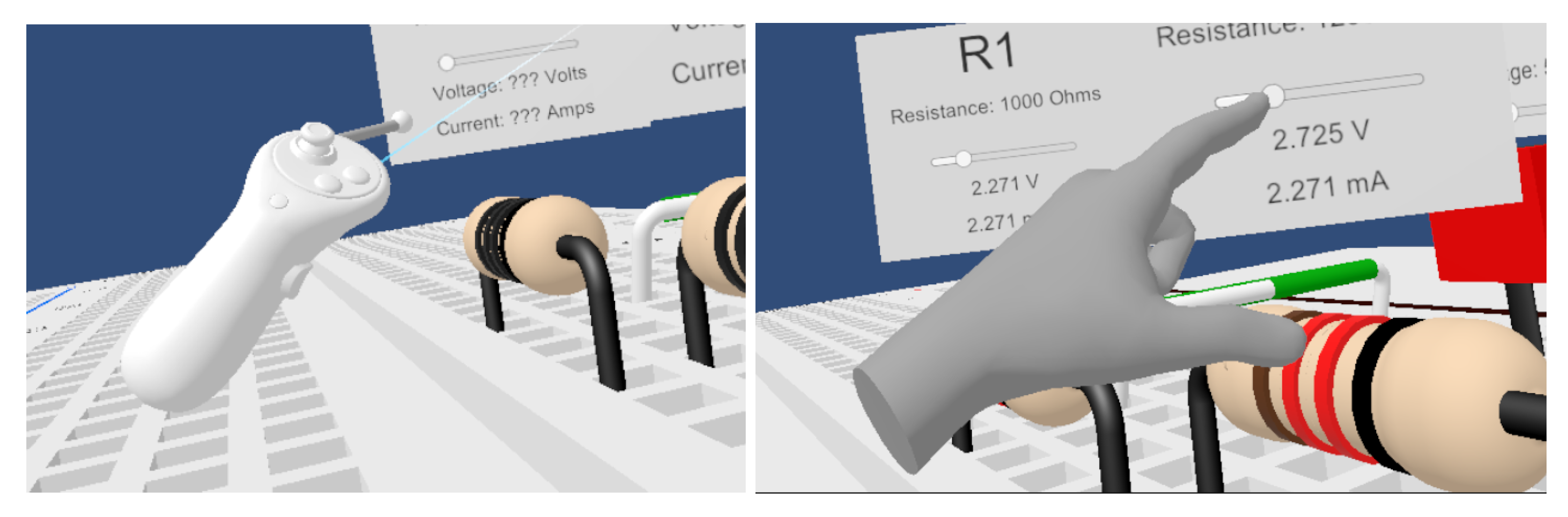
Figure 2.
Left: Breadboard surface model, Right: Breadboard connectors for physics-based detection.
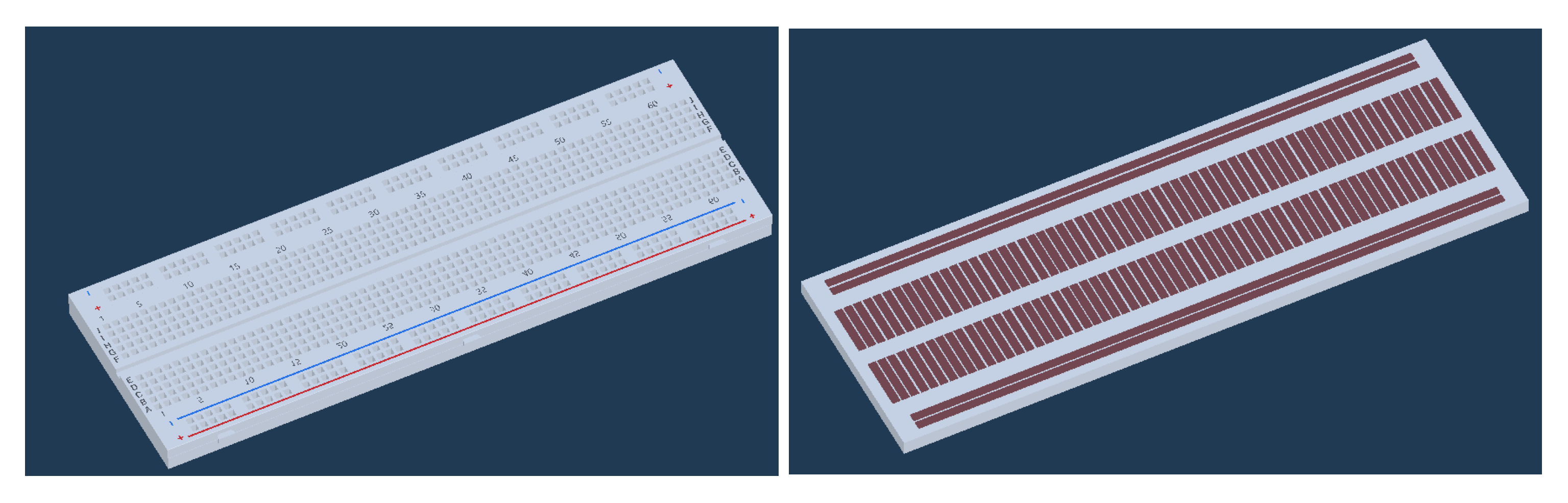
Figure 3.
Example of the structure for the Resistor GameObject.
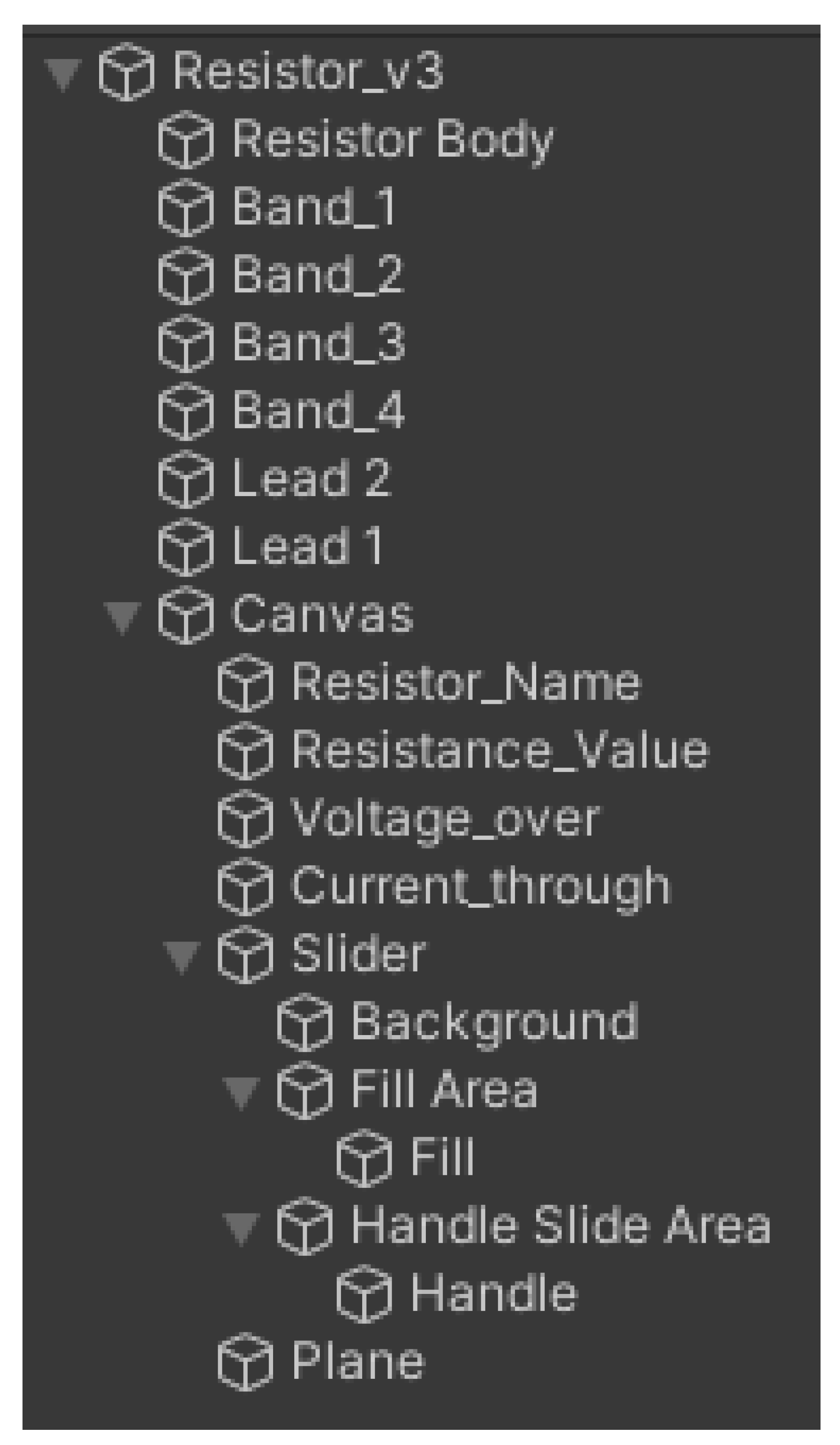
Figure 4.
Main script flowchart.
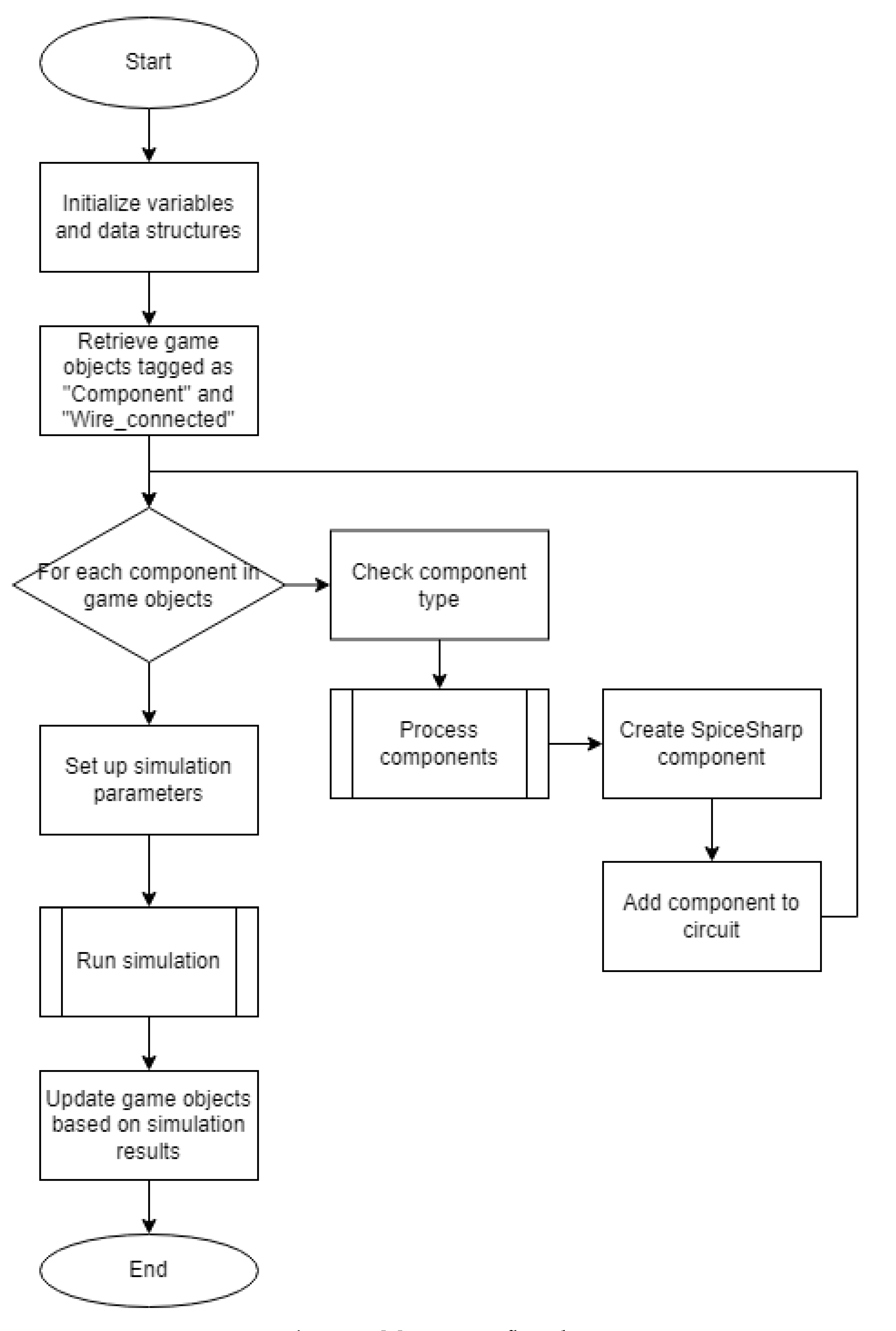
Figure 5.
Shader Graph for custom dotted texture.
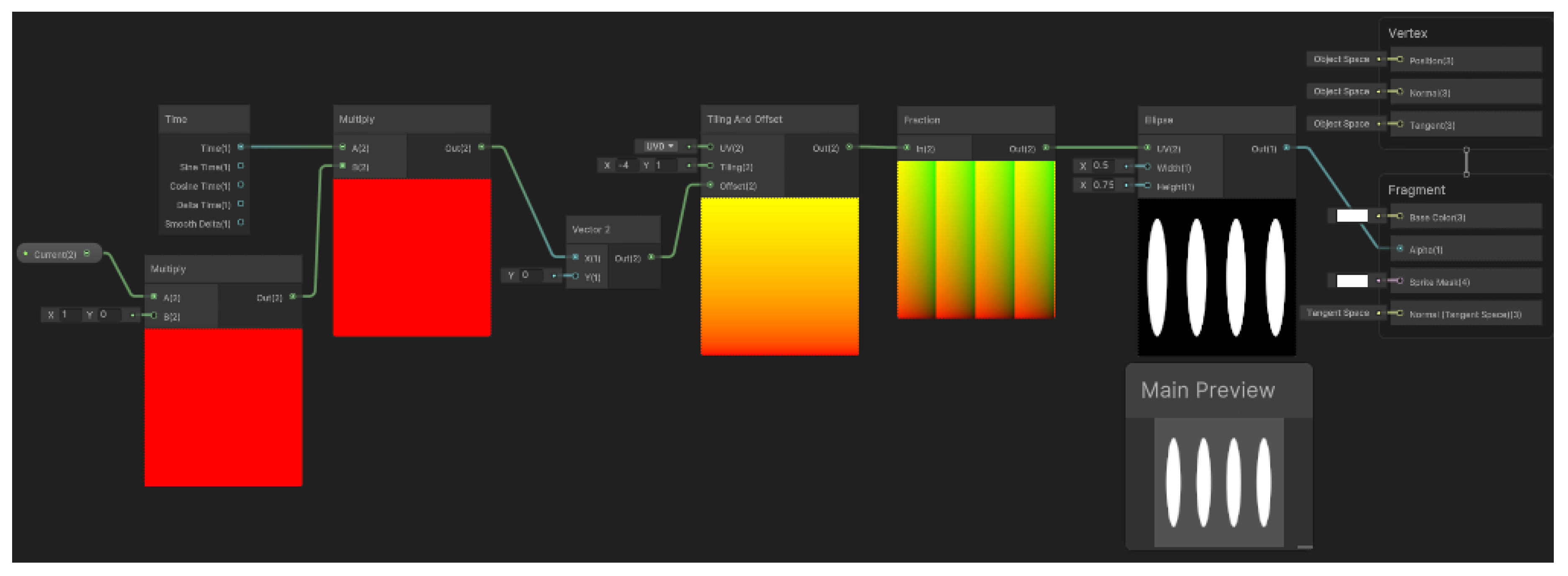
Figure 6.
Example of Line Renderers showing the current path as dots appearing to be moving from left to right.
Figure 6.
Example of Line Renderers showing the current path as dots appearing to be moving from left to right.
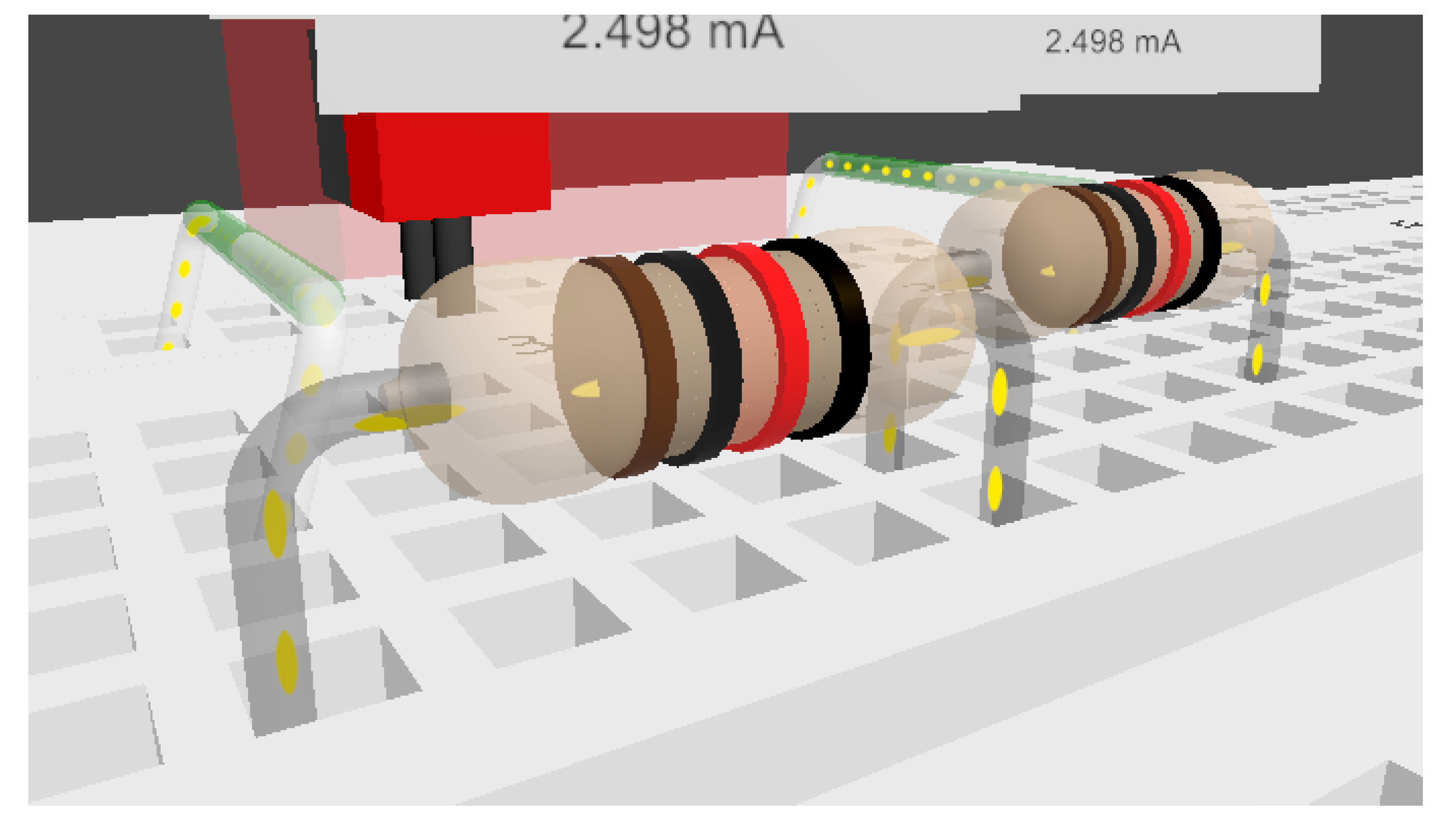
Figure 7.
Simulated resistor network with current and voltage visualized.
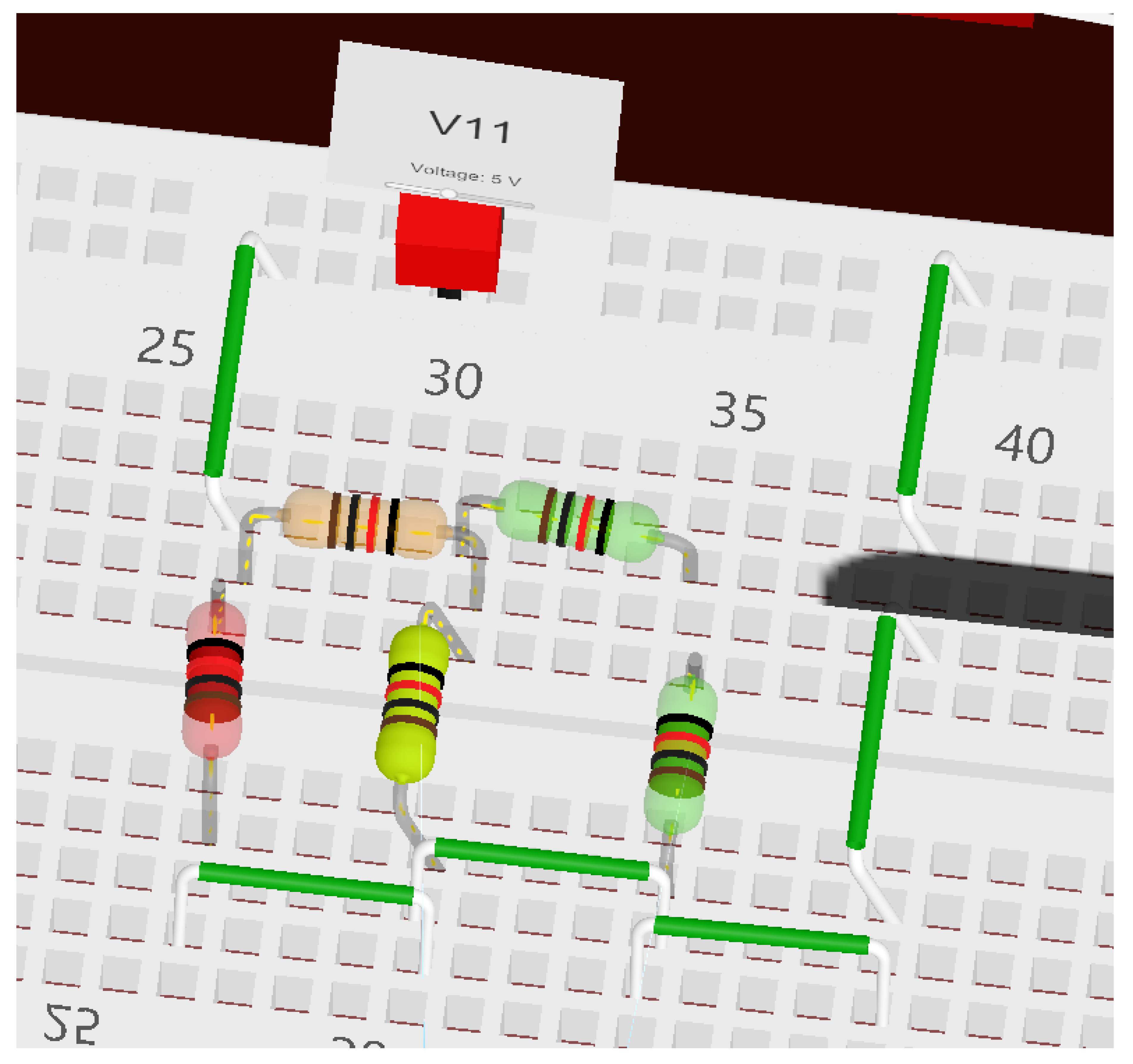
Figure 8.
Top-down view of the two digital ICs wired to the breadboard.

Disclaimer/Publisher’s Note: The statements, opinions and data contained in all publications are solely those of the individual author(s) and contributor(s) and not of MDPI and/or the editor(s). MDPI and/or the editor(s) disclaim responsibility for any injury to people or property resulting from any ideas, methods, instructions or products referred to in the content. |
© 2024 by the authors. Licensee MDPI, Basel, Switzerland. This article is an open access article distributed under the terms and conditions of the Creative Commons Attribution (CC BY) license (http://creativecommons.org/licenses/by/4.0/).
Copyright: This open access article is published under a Creative Commons CC BY 4.0 license, which permit the free download, distribution, and reuse, provided that the author and preprint are cited in any reuse.


