
Submitted:
24 March 2024
Posted:
26 March 2024
You are already at the latest version
Abstract
This paper concentrates on computing the efficiency of heliostat field systems. By conducting a comprehensive analysis of the mathematical model for optical efficiency, we have effectively simplified the complex three-dimensional illumination problem of heliostat fields into a two-dimensional issue. Our work primarily investigates the calculation methods for the average optical efficiency and output power of heliostat. Traditionally, calculating shadow and blocking efficiency, key factors affecting the optical performance of mirror fields, has posed a significant technical challenge. Through innovative improvements to the Monte Carlo simulation technique, this study has successfully reduced the spatial dimensionality of the problem. We employed a series of novel coordinate transformations to simulate light tracing on a two-dimensional plane, thereby efficiently calculating the efficiency of shadows and obstructions. Not only have we solved the computational challenges of shadow and obstruction efficiency, but our unique algorithm design also allows us to precisely obtain the overall average optical efficiency of the heliostat field while enhancing computational efficiency.
Keywords:
heliostat field
; Monte Carlo simulation
; light tracing
; optimal design
1. Introduction
This study focuses on the efficiency of a heliostat field system for focusing sunlight to a collector, where the average annual thermal power output and optical efficiency are the key metrics for evaluating its performance. These metrics include five core components: shadow shading efficiency, cosine efficiency, atmospheric transmittance, collector truncation efficiency, and mirror reflectance. In this work, a heliostat field located at a specific east longitude, north latitude and altitude with a specific radius is selected as the research object, and the corresponding mathematical model of optical efficiency is established to facilitate the calculation of these five indexes. The calculation of the shadowing and occlusion efficiency is particularly complicated, and we convert the original three-dimensional problem into a two-dimensional planar problem[1] by establishing the transformation matrices between the mirror coordinate system and the mirror field coordinate system, which are processed with the help of the improved Monte Carlo simulation method. Using these transformation matrices for coordinate transformation, ray tracing simulations are performed on the 2D plane, and the shadowing and occlusion efficiencies are successfully calculated. Meanwhile, the parallel computation is accelerated by further improvement of the Monte Carlo algorithm, which improves the computational efficiency of other average optical efficiencies of the fixed-heaven mirror field. In the end, we simplified the calculation of the annual average thermal power output and other related performance indexes by using the five time points of 9:00, 10:30, 12:00, 13:30 and 15:00 on the 21st day of each month as the "annual average indexes".
2. Modeling of Heliostat Field and Efficiency Calculations
2.1. Modeling of Heliostat Field
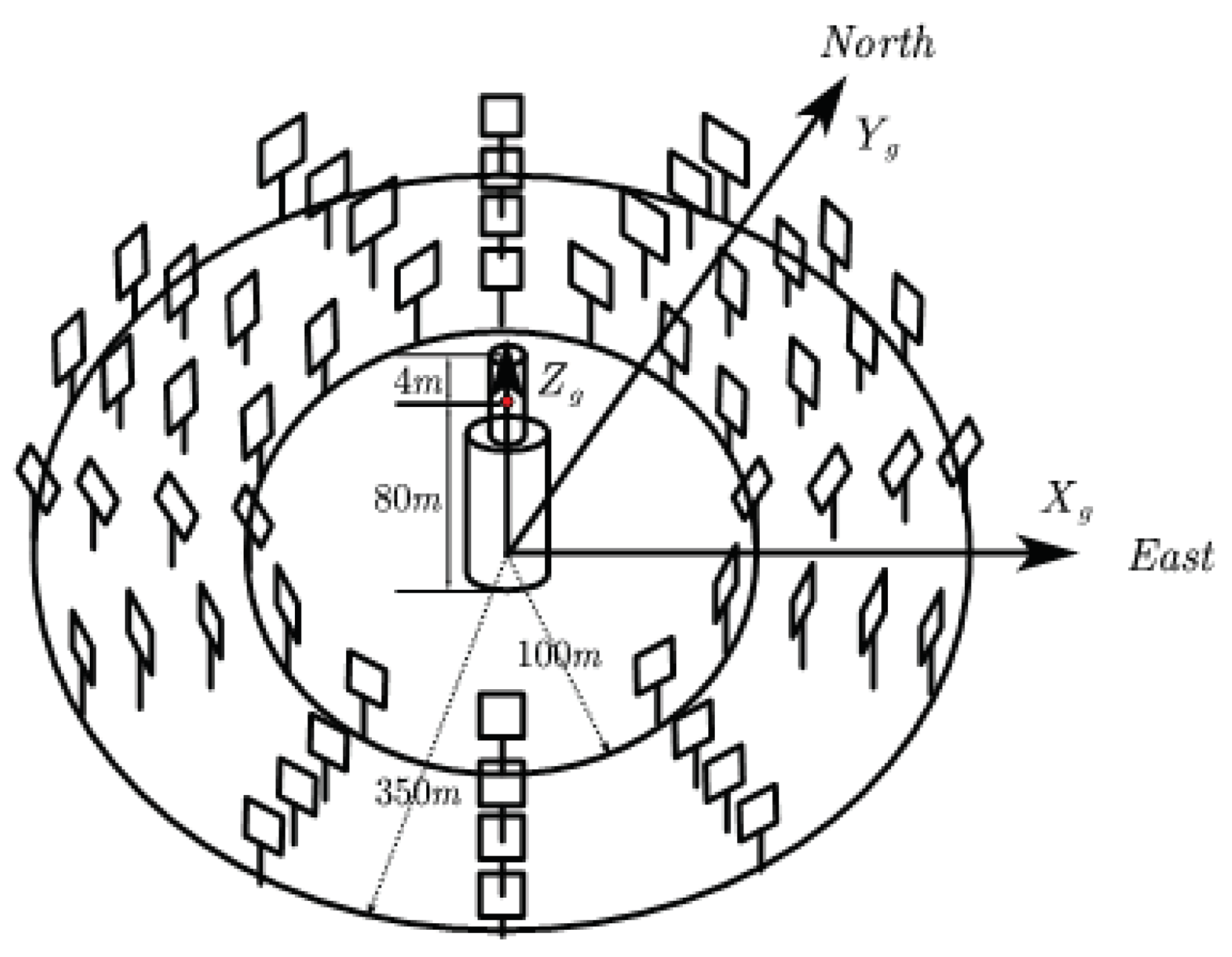
The distribution of the heliostat field is shown in the figure below, with the center of the absorber tower base as the origin, the due east direction as the positive direction of the axis, the due north direction as the positive direction of the axis, and perpendicular to the center of the absorber tower base upward as the positive direction of the axis.
Figure 1.
Schematic diagram of the heliostat field coordinate system
2.2. Cosine Efficiency
For a single heliostat, the cosine efficiency can reach its maximum value only when the incident ray vector is parallel to the reflected ray vector and the normal vector.The derivation of the cosine efficiency calculation is as follows:
The solar altitude angle and solar azimuth angle are:
where denotes local latitude, with north latitude being positive; denotes solar time angle, denotes local time, denotes solar declination, and D denotes the number of days counted from the vernal equinox as the 0th day.
The position of the sun can be represented by the solar altitude angle and the solar azimuth angle , and for the light incident on the heliostat the vector is represented as , with coordinates:
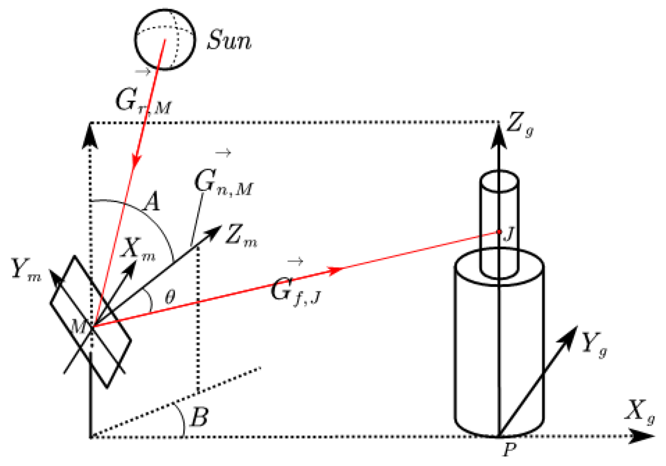
As shown in the Figure 2, in the heliostat field , the collector center coordinates for , where for the height of the absorber tower, for any heliostat field center , its coordinates for , where M for the heliostat field center and i denotes the heliostat field mirror. Vector represents the unit vector J pointing to the center of the collector from the center of the heliostat field , denoted as:
According to the law of reflection of light, the mirror normal vector bisects the angle between the incident unit vector and the reflected unit vector :
Then the heliostat pitch angle A and heliostat azimuth angle B can be derived from the mirror normal vector
As shown in the Figure 2, there is an angle between the incident or reflected ray and the normal, where the cosine value is the value of the cosine efficiency of that fixed-sun mirror:
where denotes the opposite direction of incident light:
2.3. shadow Shading Efficiency
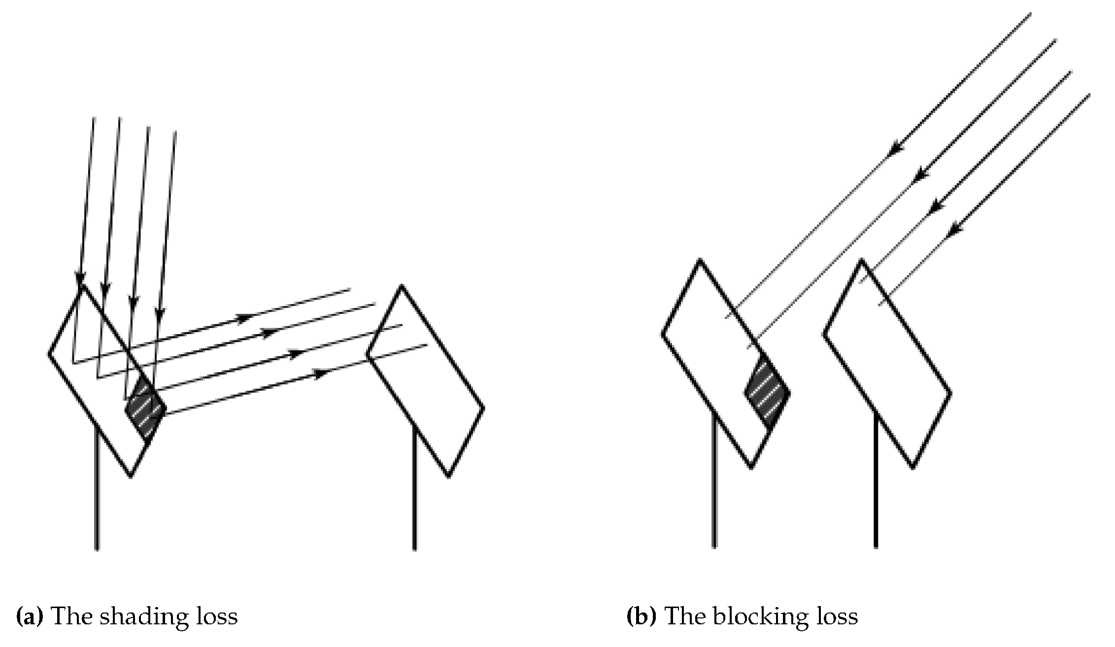
In heliostat fields, not all incident and reflected sunlight can be perfectly focused on the central receiver, leading to two primary types of optical losses. First, shadow loss occurs when certain heliostats, referred to as obstructing heliostats, block sunlight that should ideally reach a targeted heliostat. Secondly, blocking loss arises when light, reflected off the target heliostat, is intercepted by heliostats positioned in front of it. These phenomena, distinguishing between shadow and blocking losses, are critical to understanding and optimizing the efficiency of heliostat fields.The blocking loss and shading loss of the mirror are shown below:
Figure 3.
Schematic diagram of blocking loss and shadow loss for mirrors
Not all heliostats surrounding a target heliostat are considered obstructing heliostats. According to reference [1], it is sufficient to consider only the heliostats located in the immediate vicinity of the target heliostat. Given that the distance between the centers of adjacent heliostat bases exceeds the width of the mirror surface by 5 meters, the area of concern for obstructing heliostats is defined by a circle centered on the base of the target heliostat with a radius of 11 meters.
As illustrated in Figure 2, we establish a mirror coordinate system for the heliostat, designating the center of the mirror surface, M, as the origin. The axis is defined by a line passing through the origin and parallel to the mirror’s width, while the axis is defined by a line passing through the origin and perpendicular to the mirror’s width. Additionally, the axis is defined by a line passing through the origin and perpendicular to the plane, with orientations as depicted in the figure. Our objective is to determine whether a ray of light, encompassing both incident and reflected rays, passing through a point on mirror a, will intersect mirror b. If so, the intersection point on mirror b, denoted as , is expressed in the mirror’s coordinate system[1].
For a mirror in a heliosta field, the horizontal axis controls the pitch angle of the mirror and the vertical axis controls the azimuth angle of the mirror, and we can derive the transformation matrix between the mirror coordinate system and the mirror field coordinate system from the pitch angle and the azimuth angle as follows:
where A represents the heliostat pitch Angle and B represents the heliostat azimuth Angle, which are given by equation 5.
For a point in mirror A, it is converted from mirror coordinate to coordinate in heliostat field coordinate system, the calculation process is as follows:
where represents the center of mirror a, that is, the coordinates of the origin of the mirror a coordinate system within the field coordinate system, denoted by .
The transformation of point from the field coordinate system to the coordinate system of mirror b, resulting in :
Where represents the center of mirror b, which is the coordinates of the origin of mirror b’s coordinate system within the field coordinate system, denoted by .
When a beam of light enters the heliostat coordinate system, its vector representation is denoted as In the field coordinate system, the vector representation is . The transformation relationship between them is as follows:
Summarizing the above, with the point known within the coordinate system of mirror b, along with the light vector , we can determine the intersection point of the light vector with the plane of mirror b in its coordinate system. The relationship between them is as follows:
If and , then point falls within the range of mirror b, indicating it is within the shadow and blocking area.
Therefore, we employ the Monte Carlo simulation algorithm to uniformly generate points on the rectangular surface of mirror a. Through the calculation process described above, we determine which of these points fall onto mirror b. Let the number of points falling onto mirror b be denoted by . Consequently, the shadow and blocking efficiency, , is defined as follows:
2.4. Collector Truncation Efficiency
The collector truncation efficiency refers to the ratio of the solar radiant energy actually captured by the solar collector to the theoretical maximum that could be captured. In practice, there are certain losses in the energy radiated to the collector, such as those due to the precision limitations of the heliostats or the displacement of the focal spot caused by swaying. This concept is essential for understanding the real-world performance of solar thermal systems and identifying areas for technological improvement.
To calculate the collector truncation efficiency, we adopted the method proposed by Collado and Guallar, based on the HFLCAL model [3]:
where R denotes the radius of the collector, and represents the height of the absorption tower, which is the distance from the center of the collector to the ground. refers to the installation height of the heliostat. signifies the angle formed by the incident (or reflected) light rays with the normal. The total impact factoris determined by a combination of factors: , which represents the solar shape error; , which accounts for the beam quality error; , denoting the astigmatism error; and , which stands for the tracking error. The calculation process for these components is as follows:
where the values for are referenced from relevant literature [4]. Specifically, is set at 2.51 mrad, at 0.63 mrad, and , where denotes the slope error and is valued at 0.94 mrad.
The astigmatism error is calculated using the following equation:
where and respectively represent the height and width of the heliostat, while denotes the distance from the center of the heliostat to the center of the collector, which is significantly greater than the dimensions of the heliostat. This substantial difference causes the denominator of the equation, , to be much larger than the value of the numerator, leading to the approximation that the value of is effectively 0.
2.5. Atmospheric Transmittance and Mirror Reflectance
i.atmospheric transmittance
The atmospheric transmittance in a heliostat field refers to the extent to which sunlight is affected by absorption, scattering, and refraction as it passes through the atmosphere to reach the heliostats. It quantifies the proportion of sunlight that is successfully received by the heliostats [6].
where denotes the distance from the center of the heliostat to the center of the collector.
ii.mirror reflectance
The mirror reflectance, , in a heliostat field denotes the proportion of sunlight that is reflected by the surface of the heliostats upon incidence. It reflects the ability of the heliostats to redirect incoming solar radiation towards the target receiver. This parameter can be considered a constant, with a typical value of .
2.6. Optical Efficiency and Thermal Power Output
i.optical efficiency
Summarizing the 5 methods of calculating optical efficiency, we can use the following formula to calculate the total optical efficiency [5]:
ii.thermal power output
The output thermal power of a heliostat field depends on several factors, and it is given by the following equation:
where denotes the total number of heliostat mirrors, denotes the normal direct radiation irradiance, denotes the optical efficiency of the mirror, and denotes the light-gathering area of the mirror.
Normal direct radiation irradiance is the irradiance of sunlight directed onto the ground in a direction perpendicular to the ground. It represents the amount of solar energy received per unit area, as follows [7]:
where represents the solar constant, which is valued at 1.366 kW/m2, and H denotes the altitude, measured in kilometers.
3. Results and Discussion
To calculate the annual average output thermal power, it is necessary first to determine the average monthly output thermal power. To simplify the calculations, we assume the 21st day of each month represents the average monthly output thermal power. On the 21st of each month, the average output thermal power is determined by taking the mean of the output thermal power at five specific time points: 9:00, 10:30, 12:00, 13:30, and 15:00, which serves as the daily average output thermal power. The output thermal power for each of these moments can be derived from Equation 20. Through this step-by-step approach, the annual average output thermal power can be calculated.
For the cosine efficiency, we take the cosine efficiency for each of the four moments of the heliostat field at the summer solstice, June 22 of that year, and show them as follows:
Figure 4.
Summer solstice cosine efficiency
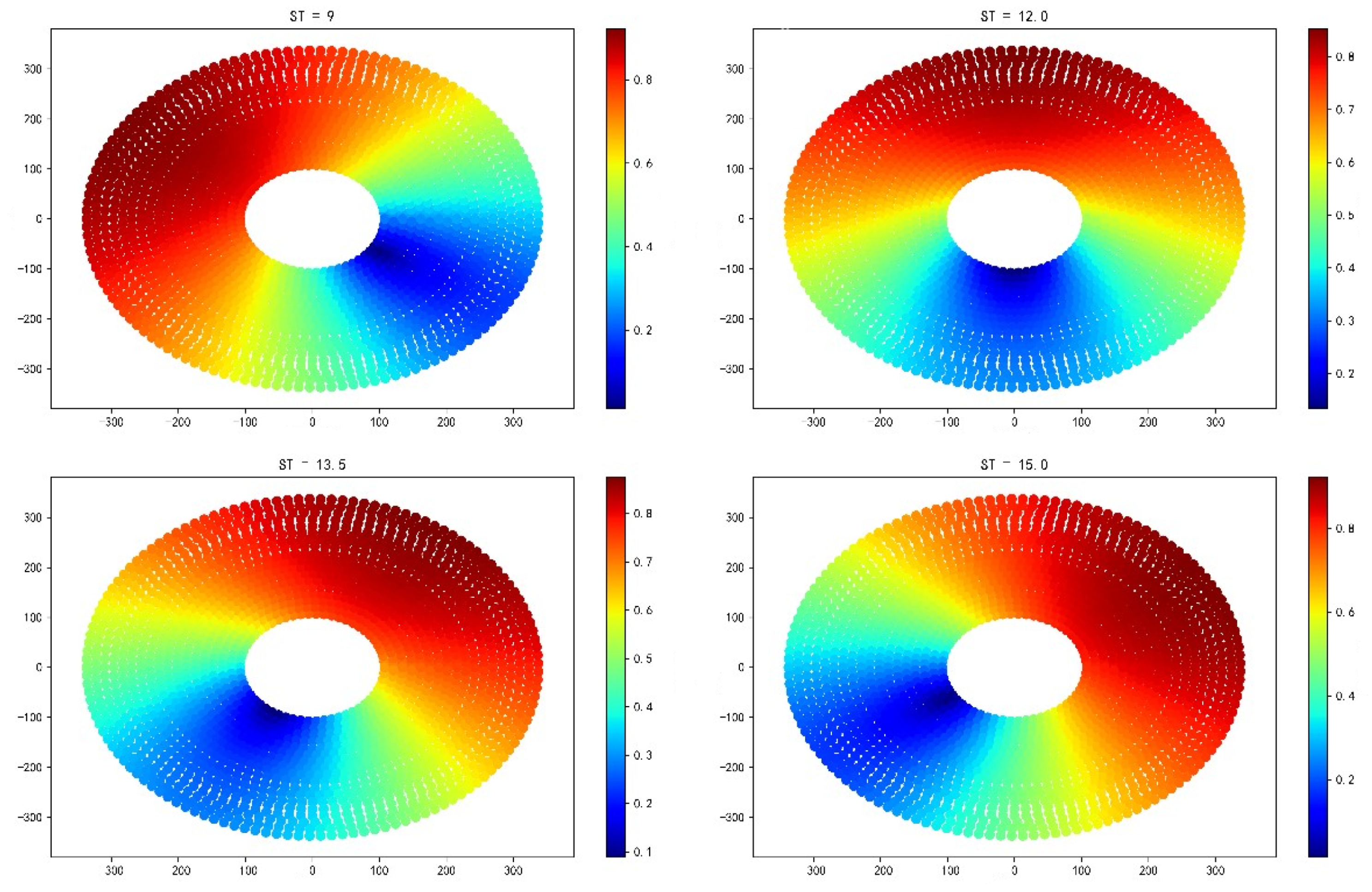
From the analysis of the above figure, it can be seen that for different moments of the day, due to the difference between the sun’s altitude angle and the sun’s azimuth angle, it will result in different scope of the mirror field in different moments of the cosine efficiency of the region where the higher cosine efficiency is located, but on the whole, the cosine efficiency of the northern heliostat is larger than that of the southern.
For the collector truncation efficiency for each of the four time points in the heliostat field for the summer solstice, June 22 of that year, the results are shown below:
Figure 5.
Summer solstice collector truncation efficiency
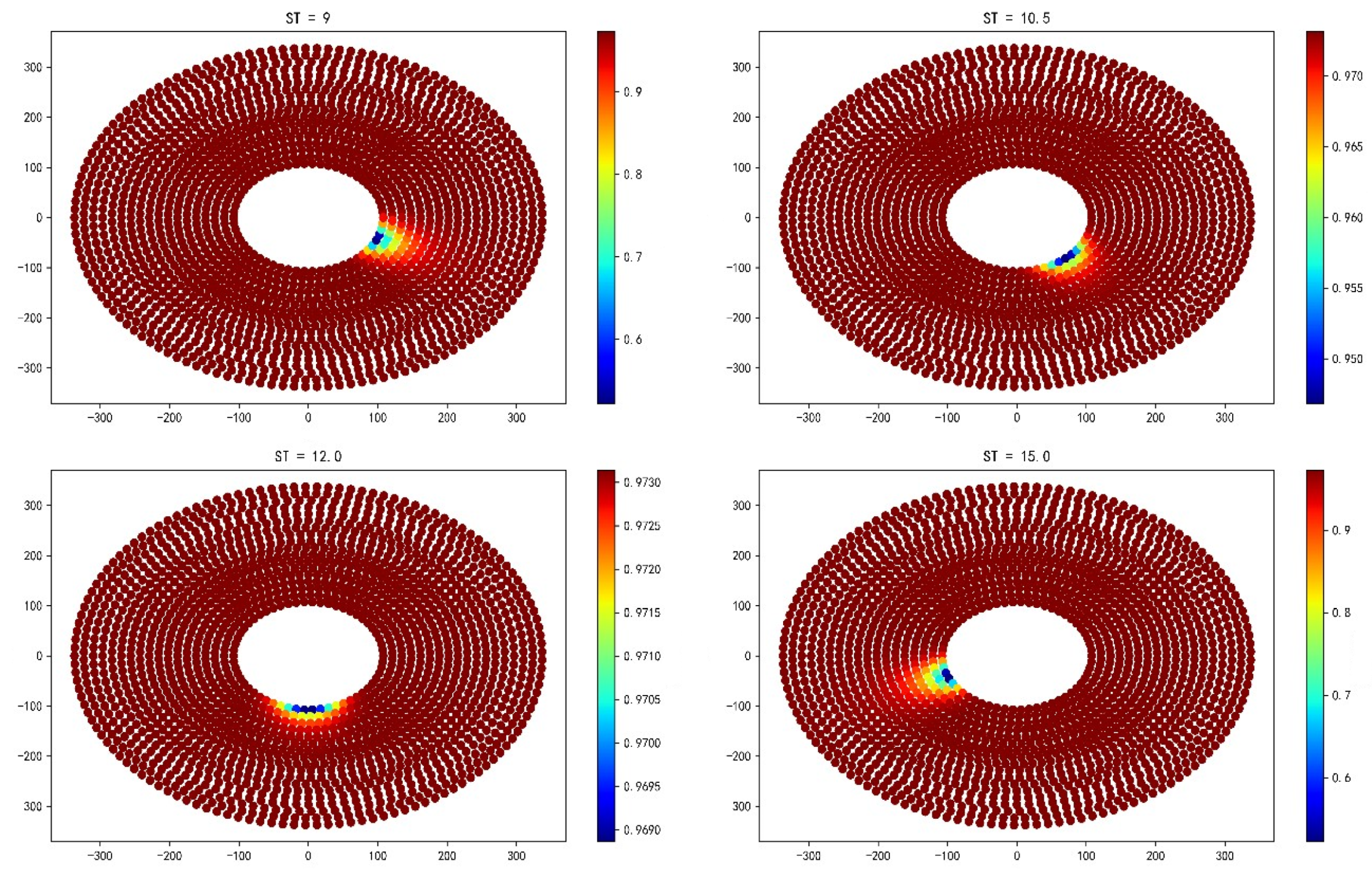
Analyzing the above figure, it can be seen that for the collector truncation efficiency, most of the mirrors in the field of heliosta mirrors are higher, only a small portion of them will show a certain degree of regularity to reduce with the change of the sun’s position, and for this small portion, the closer to the absorption tower, the more obvious the reduction.
For the atmospheric transmittance of each heliostat in this heliostat field, the results are shown below:
Figure 6.
Summer solstice atmospheric transmittance efficiency
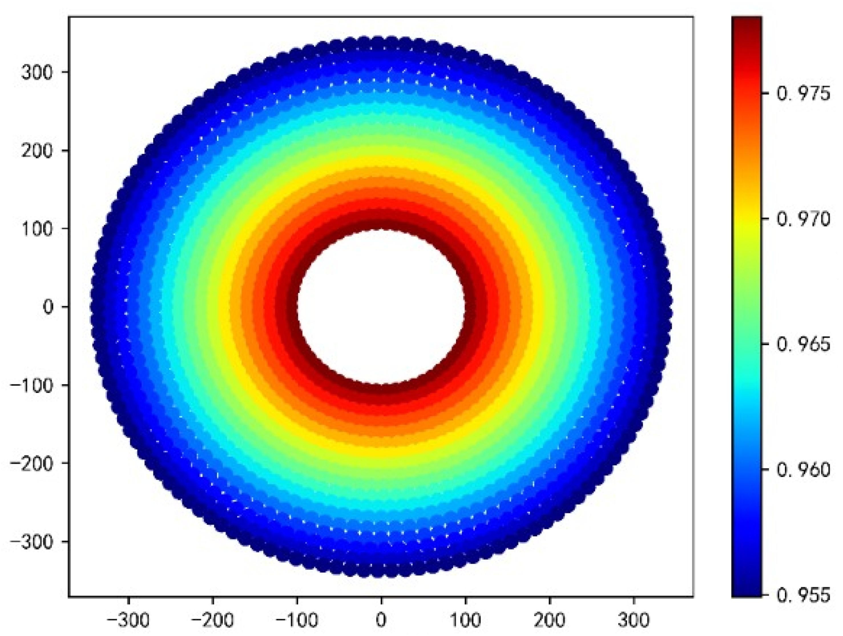
Analyzing the above figure, it can be seen that the atmospheric transmittance in the mirror field shows an extremely obvious regular arrangement, the closer to the absorber tower’s heliostat, the greater its atmospheric transmittance, and vice versa the smaller.

Table 1.
This is a two-row, six-column table.
| Optical Efficiency | Cosine Efficiency | Shadow Shading Efficiency | Truncation Efficiency | Thermal Power Output (MW) | Hermal Output per Unit Area (kW/m2) |
|---|---|---|---|---|---|
| 0.5533 | 0.6836 | 0.9419 | 0.9673 | 33.5254 | 0.5337 |
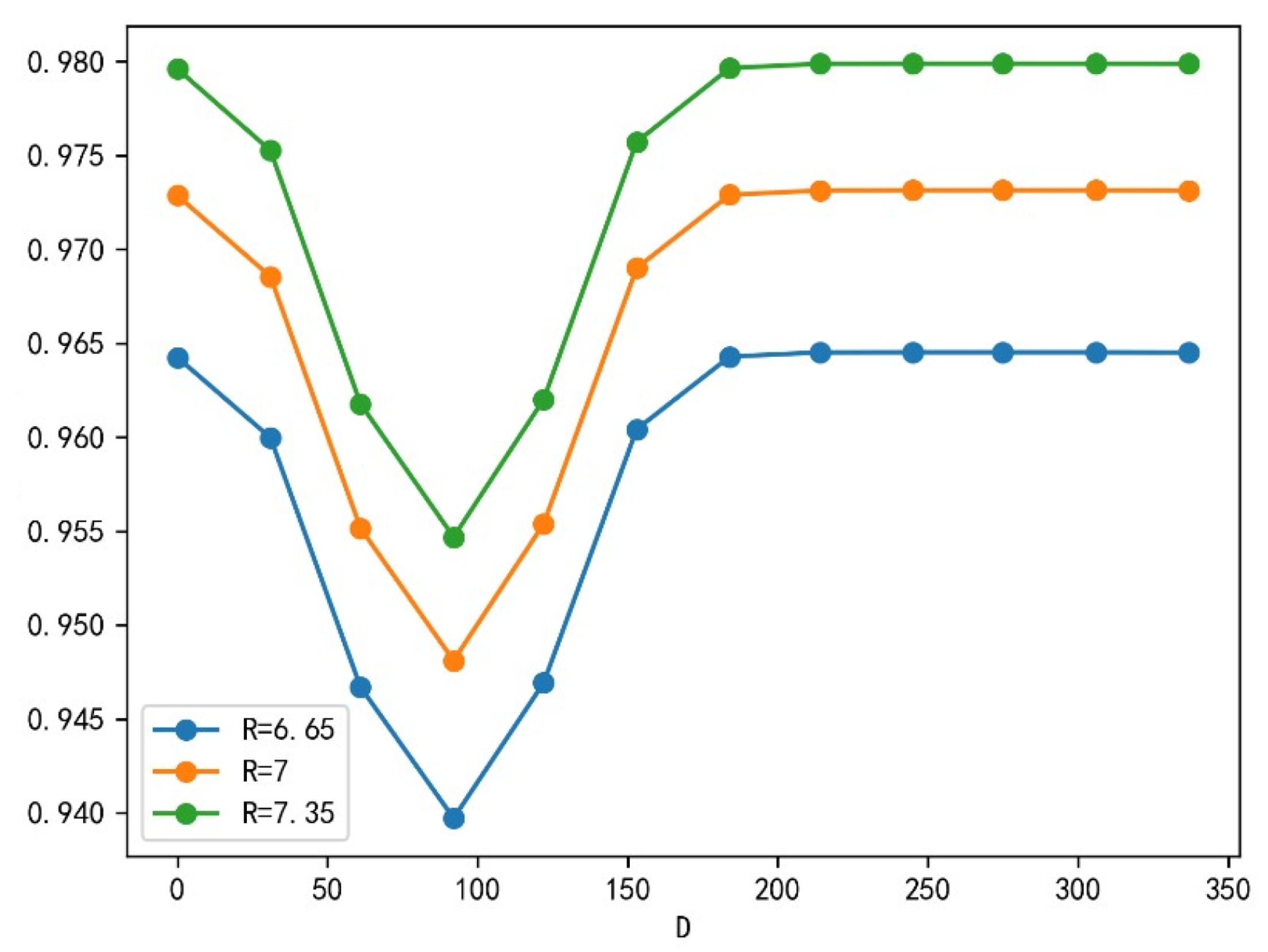
Then, in order to verify the accuracy of the mathematical model of the optical efficiency of heliostat field, the collector diameter is selected and its potential effect on the average optical efficiency is analyzed.
By calculating the truncation efficiency of the floating values respectively, and by observing the sensitivity analysis diagram of the truncation efficiency, we find that the shadow generated by the change of the height and diameter of the collector will not have a great impact on the average optical efficiency, and our model has a certain accuracy.
Figure 7.
Truncation efficiency sensitivity analysis
4. Conclusions
This study constructed a comprehensive mathematical model for calculating the optical efficiency and power output of a heliostat field. The model is based on the variation of the sun’s rays, and Monte Carlo simulations are used for ray tracing, an innovative method that accurately simulates the trajectory of the rays. At the same time, our calculations are entirely based on fundamental mathematical formulas, ensuring the reliability of the model on an innovative basis. In addition, the reliability of the model is verified by sensitivity analysis.The mathematical model we developed is also very extensible and can be applied to different heliostat fields, and also provides a good basis for future consideration of weather changes and mirror deformation.
Author Contributions
Author Contributions: Conceptualization, Tengda Xu, Junliang Wu, Yangteng Wei and QinJiajia; methodology, Tengda Xu and Yangteng We; software,Yangteng Wei; formal analysis, Tengda Xu and Junliang Wu; investigation, Tengda Xu; writing—original draft preparation, Tengda Xu; writing—review and editing, Tengda Xu and QinJiajia. All authors have read and agreed to the published version of the manuscript.
Funding
This project is supported by the University of South China, School of Nuclear Science and Technology.
Data Availability Statement
All the data of this project are true and reliable. The data of heliostat field is provided in the attachment.
Conflicts of Interest
The authors declare no conflicts of interest.
Appendix A. Basic data of heliostat field
For example, the heliostatic field in a circular domain with a radius of and a longitude of 98.5° E, latitude of 39.4° N, altitude of 3km is taken as the center. Among them, the height of the absorption tower is , the collector is cylindrical, the height is , the radius is , and the heliostat is built away from the absorption tower. For heliostat, the distance between the two sides parallel to the ground is the mirror height, the distance between the left and right sides is the mirror width, the mirror broadband is greater than or equal to the mirror height, and the side length is limited to to . The heliostat height is the height of the heliostat center to the ground, the height is limited to to , and at the same time to ensure that the heliostat will not touch the ground when rotating, the adjacent heliostat should be more than more than the mirror width.
Appendix B. Average optical efficiency and output power on 21 days per month
Table A1.
Monthly average optical efficiency and output power on the 21st
| Month | Optical Efficiency | Cosine Efficiency | Shadow Shading Efficiency | Truncation Efficiency | Thermal Output per Unit Area (kW/m2) |
|---|---|---|---|---|---|
| January 21 | 0.5969 | 0.7376 | 0.9362 | 0.9731 | 0.5205 |
| February 21 | 0.5858 | 0.7143 | 0.9489 | 0.9731 | 0.5528 |
| March 21 | 0.5615 | 0.6848 | 0.9490 | 0.9729 | 0.5588 |
| April 21 | 0.5276 | 0.6510 | 0.9422 | 0.9686 | 0.5429 |
| May 21 | 0.5017 | 0.6272 | 0.9430 | 0.9552 | 0.5241 |
| June 21 | 0.4908 | 0.6188 | 0.9421 | 0.9481 | 0.5149 |
| July 21 | 0.5020 | 0.6275 | 0.9430 | 0.9554 | 0.5244 |
| August 21 | 0.5290 | 0.6525 | 0.9421 | 0.9690 | 0.5438 |
| September 21 | 0.5633 | 0.6865 | 0.9496 | 0.9729 | 0.5593 |
| October 21 | 0.5879 | 0.7175 | 0.9480 | 0.9731 | 0.5502 |
| November 21 | 0.5970 | 0.7394 | 0.9343 | 0.9731 | 0.5162 |
| December 21 | 0.5964 | 0.7463 | 0.9246 | 0.9731 | 0.4961 |
References
- Xie Q, Guo Z, Liu D, et al. Optimization of heliostat field distribution based on improved Gray Wolf optimization algorithm[J]. Renewable Energy, 2021, 176: 447-458. [CrossRef]
- Cai, C.-J. Solar shadow localization. Mathematical Modeling and its Applications 2015, 4, 25–33. [Google Scholar]
- Deng L, Wu Y, Guo S, et al. Rose pattern for heliostat field optimization with a dynamic speciation-based mutation differential evolution[J]. International Journal of Energy Research, 2019, 44(3): 1951-1970. [CrossRef]
- Collado F J, Guallar J. A review of optimized design layouts for solar power tower plants with campo code[J]. Renewable and Sustainable Energy Reviews, 2013, 20: 142-154. [CrossRef]
- ZHANG Ping,XI Zhengstian,HUA Wenhan et al. Calculation method of optical efficiency of solar tower photothermal mirror field. Technology and Market 2021, 28, 5–8.
- O. Farges, J.J. Bezian, M. El Hafi, Global optimization of solar power tower systems using a Monte Carlo algorithm: Application to a redesign of the PS10 solar thermal power plant [J], Renewable Energy, 2018, 119:345-353. [CrossRef]
- Du Yuhang et al, Impact analysis of different focusing strategies of heliostats in tower-type photovoltaic power plants[J], Journal of Power Engineering, 2020, 40(5):426-432. Journal of Power Engineering 2020, 40, 426–432.
Figure 2.
Schematic diagram of mirror coordinate system and field coordinate system
Disclaimer/Publisher’s Note: The statements, opinions and data contained in all publications are solely those of the individual author(s) and contributor(s) and not of MDPI and/or the editor(s). MDPI and/or the editor(s) disclaim responsibility for any injury to people or property resulting from any ideas, methods, instructions or products referred to in the content. |
© 2024 by the authors. Licensee MDPI, Basel, Switzerland. This article is an open access article distributed under the terms and conditions of the Creative Commons Attribution (CC BY) license (http://creativecommons.org/licenses/by/4.0/).
Copyright: This open access article is published under a Creative Commons CC BY 4.0 license, which permit the free download, distribution, and reuse, provided that the author and preprint are cited in any reuse.


