
Submitted:
19 February 2024
Posted:
20 February 2024
You are already at the latest version
Abstract
This investigation mainly focused on the microstructural analysis of Al based hybrid metal matrix composites. Aluminium as base metal and reinforced with 2% B4 C, ZrO2 (2%,4%,6%), SiC (4%,8%,12%). Specimens were manufactured by using conventional stir casting technique. Hybrid metal matrix composites were examined by using Scanning electron microscope. This research explained XRD, EDS and Fractography analysis. This investigation shows the reinforced material has given better results in all aspects than pure Al6061 alloy and homogeneous dispersion of particles inside the matrix. Porosity, delamination, cracks, particle distributions were observed through microstructural analysis. Additionally determined the crystal size of pure Aluminium 6061 alloy and hybrid composites.
Keywords:
Hybrid Metal Matrix Composites
; XRD
; EDS
; Fractography
; Microstructural analysis
Introduction
The most promising material for structural applications is hybrid metal matrix composites (MMCs) reinforced with ceramic particles because of their excellent cohesive properties [1]. Aluminum matrix composites (AMCs) are a class of MMCs that have properties including low density, better stiffness and strength, improved resistance to abrasion, controllable temperature rise, better fatigue resistance and improved stability at extreme temperatures [2]. As a result, these alloys are used to design various components for sophisticated applications [3]. The use of composites in automotive applications has been found to dramatically reduce vehicle weight, energy consumption and emissions [4,5]. For these uses, Composites strengthened with alumina (3.9 g/cm3) and silicon carbide (3.18 g/cm3), or nanoparticles are iq1nteresting substrates [6]. Based on the reinforcement composition, the mass of composites increases because this reinforcement has higher density than aluminum composites (2.7 g/cm3) [7].
AA6061 is preferred as a matrix material, and the main alloys are precipitation hardened alloys included with major alloying elements such as magnesium and silicon [8]. It exhibits good mechanical strength, excellent chemical properties, good wettability behaviour and high wear resistance. It has an ultimate tensile strength of 310 MPa and thermal conductivity of 152 W/mK. Alloy 6061 is a compact, granular alloy that improves the modulus of flexibility of the compliant material. Creating metal matrix reinforced alloys with different weights of B4C, ZrO2 and SiC can improve the ductility and wear properties of the aluminum alloy. The mechanical and chemical properties of AA6061 are shown in Tables 1 and 2.

Table 1.
Mechanical Properties of Matrix Alloy AA-6061.
| Material properties | value |
| Modulus of Elasticity (GPa) | 68.9 |
| Thermal conductivity (GPa) | 167 |
| Tensile strength (MPa) | 310 |
| Density(g/cm3)  | 2.70 |
Figure 1.
SEM image of AA6061.
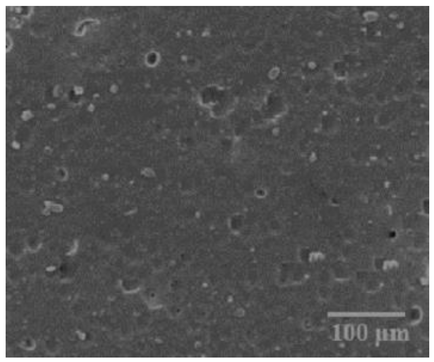
Table 2.
AA6061 chemical properties.
| Chemical | Percentage |
| Si | 0.483 |
| Mn | 0.687 |
| Zn | 0.211 |
| Cr | 0.013 |
| Ni | 0.024 |
| Ti | 0.028 |
| Pb | 0.02 |
| Fe | 0.648 |
| Cu | 0.082 |
| Mg | 0.077 |
| B | 0.002 |
| V | 0.007 |
| Al | Balance |
Reinforcement Materials
Boron Carbide (B4C)
Boron Carbide is a high hardness material. The use of boron carbide (B4C) as a reinforcing material is predicted to improve mechanical rigidity, toughness, abrasion resistance, and elasticity. The combination should be impeccably clean, resistant to degradation, and sufficient to bear high temperatures. Due to the first beneficial features of the B4C, hybrid metal matrix compounds have been postulated to use in automobile industry. The addition of B4C is to improve the tribological behaviour of Metal Matrix Composites (MMS). Boron Carbide (B4C) is a very highly abrasion substance, third in toughness only to diamonds and cubic boron nitride. It simply outperformed conventional abrasives due to their superior and economical effectiveness, including SiC and Al2O3. Manufacture of machinery and computer components, finishing and polishing of random products, High frequency trenches, Neutron integration in nuclear reactors, Antioxidant in super alloys, soldering for production of hard-faced anode and cathode, Booster propulsion systems and heavy-duty armored panels (including all-metal) are examples of processes. Compared to silicon carbide, the formation of the oxide film of silicon dioxide delays the high oxidation, which is a deficiency of boron carbide, which begins to oxidize at temperatures above 500 C.
Figure 2.
SEM image of B4C.

Table 3.
B4C chemical properties.
| Chemical | Percentage |
| C | 19.7 |
| B | 79 |
| Fe | 1 |
| Si | 0.5 |
| Ca | 0.3 |
| F | 0.03 |
Table 4.
Physical Properties of B4C.
| Material | Compressive strength | Youngs modulus | Bending strength | Melting Point |
| B4C | 1960-3922MPa | 4500 kg/mm2 | 30-50 kg/mm2 | 24550 C |
Zirconium Dioxide (ZrO2)
Zirconium Dioxide is also called zirconia and white crystalline oxide of zirconium. Baddeleyite is the most common form of mineral that has a monoclinic structural phase. Spherical zirconium, a stimulant concentrated cube shaped zirconia, is produced in various shades to be used as a crystalline material in stone and crystalline substances. The three known phases are monoclinic 11700 C, for tetragonal up to 23700 C and for cubic 23700 C.
Figure 3.
SEM image of ZrO2.
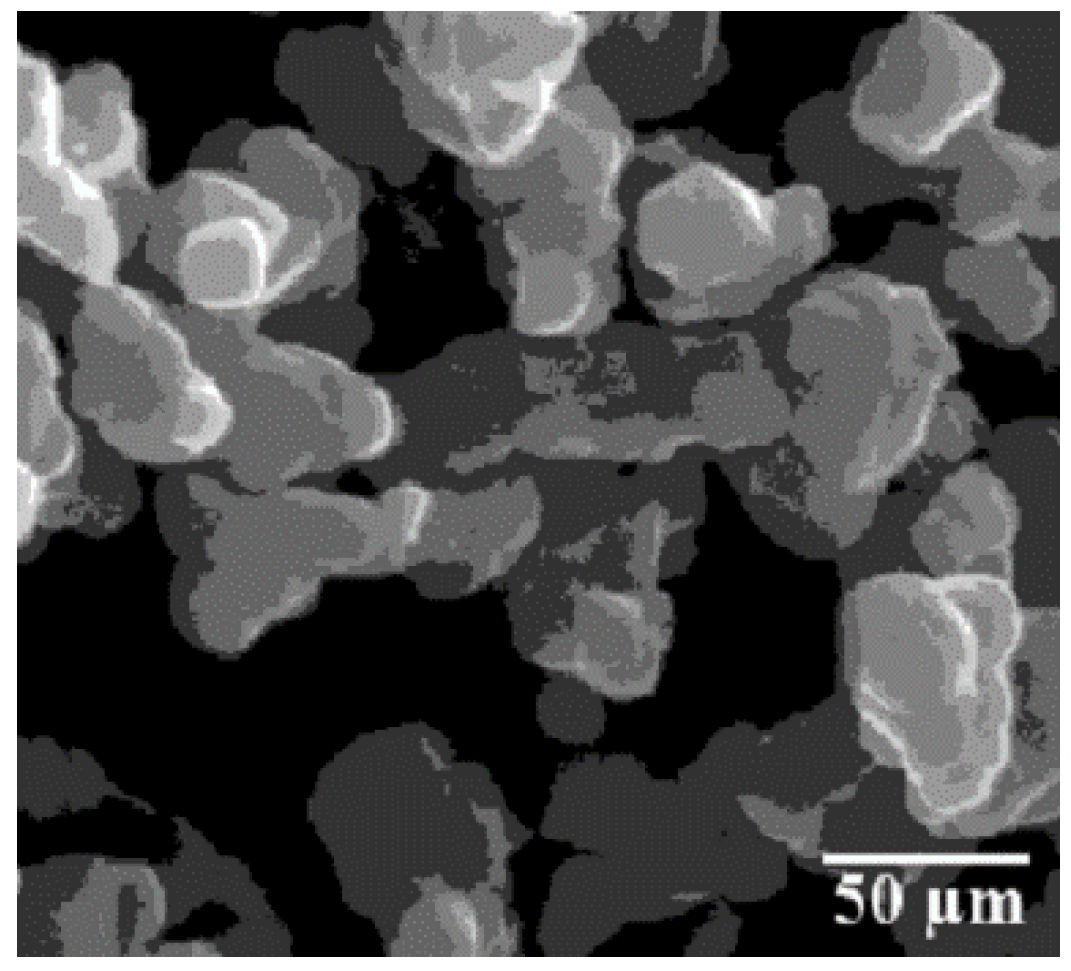
Table 5.
Properties of ZrO2.
| Properties | Value |
| Density (g/cm3) | 5.68 |
| Melting point (0C) | 2715 |
| Appearance | Powder form white |
| Molar mass | 123.218 g/mol |
Silicon Carbide (SiC)
Silicon Carbide is a hard chemical compound enhanced with silicon and carbon. To improve the mechanical strength ratio of the compound, most researchers used SiC particles as a reinforcing material. Compared to other conventional alloys, SiC has higher rigidity, strength and wear resistance and good thermal conductivity. Silicon carbide was first used in technical circuits such as light-emitting diodes (LEDs) and sensors in earlier transmitters. SiC is an n-type transistor used in the semiconductor of electronic smart devices at high temperatures and high voltages.
Figure 4.
SEM image of SiC.
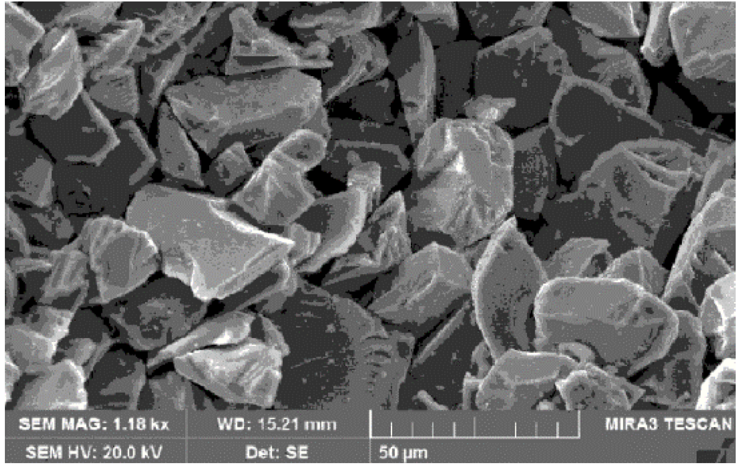
Table 6.
Chemical properties of SiC.
| Chemical | Wt. % Percentage |
| c | 0.3 |
| Al | 0.1 |
| Fe | 0.08 |
| SiO2 | 0.5 |
| Si | 0.3 |
| SiC | 98.5 |
Table 7.
Thermal and Mechanical properties of SiC.
| Properties | Value |
| Melting Point | 2730°C |
| Density | 3.22 g/cm3 |
| Poisson’s Ratio | 0.35 |
| Tensile strength | 0.1379 GPa |
| Yield strength | 21 GPa |
| Elongation | 6% |
| Thermal Conductivity | 120 W/m-K |
| Modulus of Elasticity | 90 GPa |
Research Methodology:
Stir Casting Method
Stir casting is a widely used conventional method to create hybrid metal matrix composites. Figure 6. shows the experiment structure of the stir casting process used to fabricate hybrid metal matrix composites. To create metal matrix composites, a stir casting method was used, in which the reinforcing materials were spread using a rotating process in molten aluminum [9]. Stir casting is one of the easiest fabrication methods and more effectiveness when compared to liquid state processing method. The specimens were prepared using conventional fabrication castings procedures, and subsequently machined according to the testing standards [10]. The mechanical mixing (stirring) distributes the reinforcing material (usually in powder form) on the aluminum matrix in a stir casting technique. For minimize contact between the two, both interfaces must be well polished to be ready for mechanical stirring. When the particles are introduced into the agitated matrix alloy, they not only absorb the nanoparticles and moreover additional contaminants including metal oxide and sludge that accumulate on the molten surface. Before pouring, air enclosures can form between the nanoparticles, changing the contact properties between the nanoparticles and melting, as well as reducing the moisture content in surfaces. Agitators are used to prevent the particles from migrating. During crystallization, the aluminum silicon carbide metal matrix alloy reaches a smooth state. The reinforcement particles remain constant throughout the densification when they reach the soft state. The final dispersion of the particles in the solid is determined by the processing properties such as material properties and volume fraction, relative density and solidification rate and the melting point of the particles during melting [11]. Continuous stirring, the configuration of the rotating systems, the position of the continuous stirring in the liquid, the melting point and the properties of the particles all introduced the scattering influence on matrix material. A vortex approach is performed to create and preserve the proper dispersion of the reinforcing particles in the matrix mixture. After the parent materials are melted, they are forcibly stirred to form a vortex on the melting surface, and the reinforcing material is then inserted at the edge of such vortex. Before the cast of slurry material, the stirring process continued for few minutes. The stirring process continued for a few minutes before the cast of slurry. Table 8 shows the hybrid composite mixtures which fabricated by the stir casting technique.
Microstructure Analysis
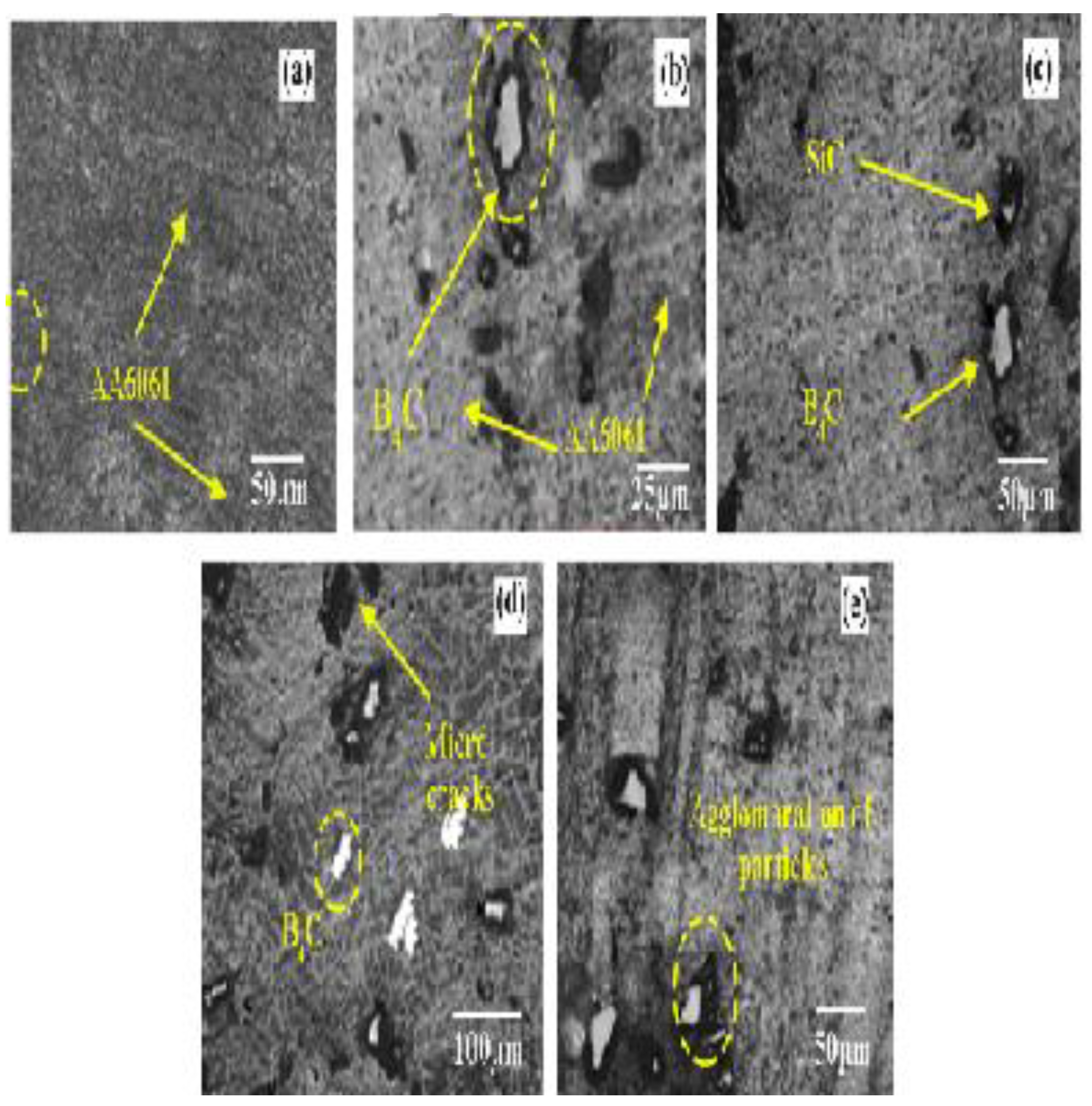
In this investigation, aluminium alloy 6061 was preferred as matrix material and B4C, ZrO2 and SiC powder particles as reinforcing materials. Figure 5, Figure 6, Figure 7 and Figure 8 illustrates the schematic SEM image of matrix and reinforced materials used in this study. For micro-structural study, the stir casting samples of various composites were divided into small sections (15 mm x 20 mm x 10 mm). The investigations reveal that the Al6061 matrix powder particle consisted of irregularly shaped spheres with an average grain size of less than 100 µm. Also, the B4C powders were found to have a complex and rounded structure with a grain size distribution ranging from 2-8 μm. The SiC particles had a complex shape and ranged from 1 to 8 μm in size. After the stir casting, particle distribution in AA6061 matrix and effect of reinforcement was revealed by Optical Electron Microscope (OEM). As can be seen in Figure 9c–e, no defects were observed in the structure of Al6061/B4C/ZrO2 /SiC in the optical photograph. This occurred as a result of high densification of the reinforcing materials simultaneously with permanent deformation throughout the stir casting process. This analysis found that the B4C/ZrO2/SiC particles in the Al6061/2%B4C/6% ZrO2 /12%SiC composites generally have a uniform dispersion in the matrices for the optical image of reinforced with ZrO2 /B4C/SiC composites, as shown in Figure 9e. In the microstructures of AA6061+2% B4C and AA6061/2%B4C/4% ZrO2 /8%SiC composites, it was shown that the production of agglomerations, microcracks are observed with the increase in ZrO2 content. Even though there were smaller pores generated in the microstructure of 12% SiC hybrid composites, it showed a higher amount of agglomeration. During the stir casting process, it was found that particle breakage occurred at some interfaces as a result of particle interaction. The research revealed a homogenous composition of SiC particles in 12% SiC compositions in the functional structure in the AA6061 matrix. The structural study shows that the was equally scattered within the hybrid matrix material and therefore, observed negligible agglomerations of SiC and B4C particles.
Figure 5.
SEM image of particle distribution for AA6061 alloy.
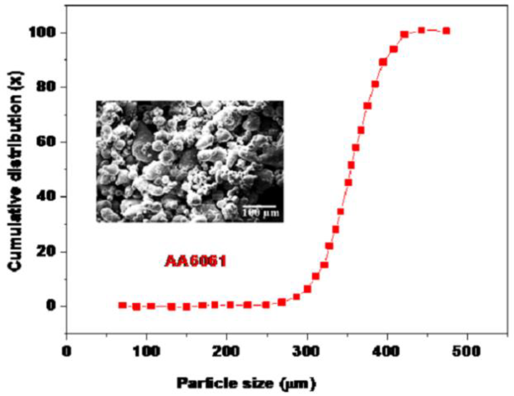
Figure 6.
SEM image of particle distribution for B4C alloy.
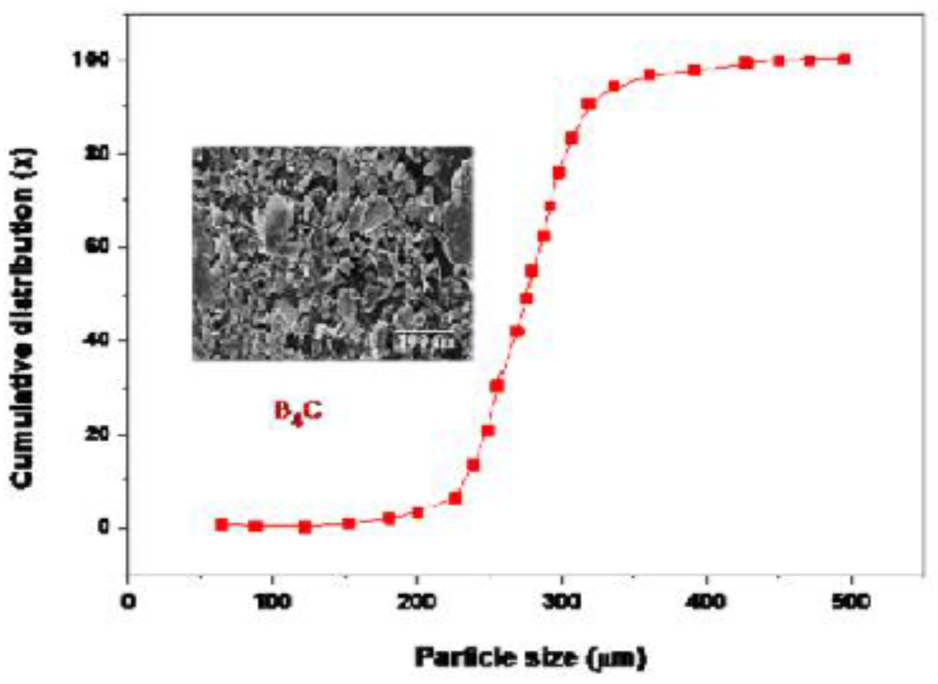
Figure 7.
SEM image of particle distribution for SiC alloy.
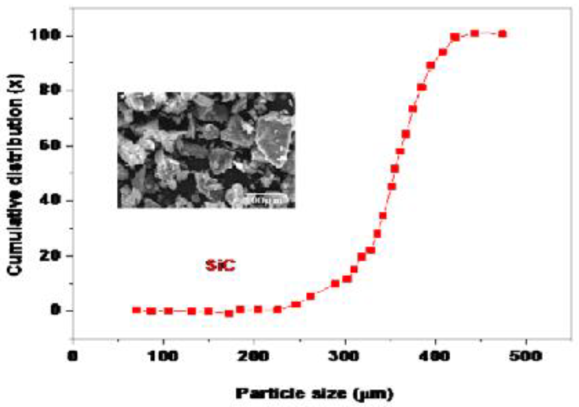
Figure 8.
SEM image of particle distribution for ZrO2 alloy.
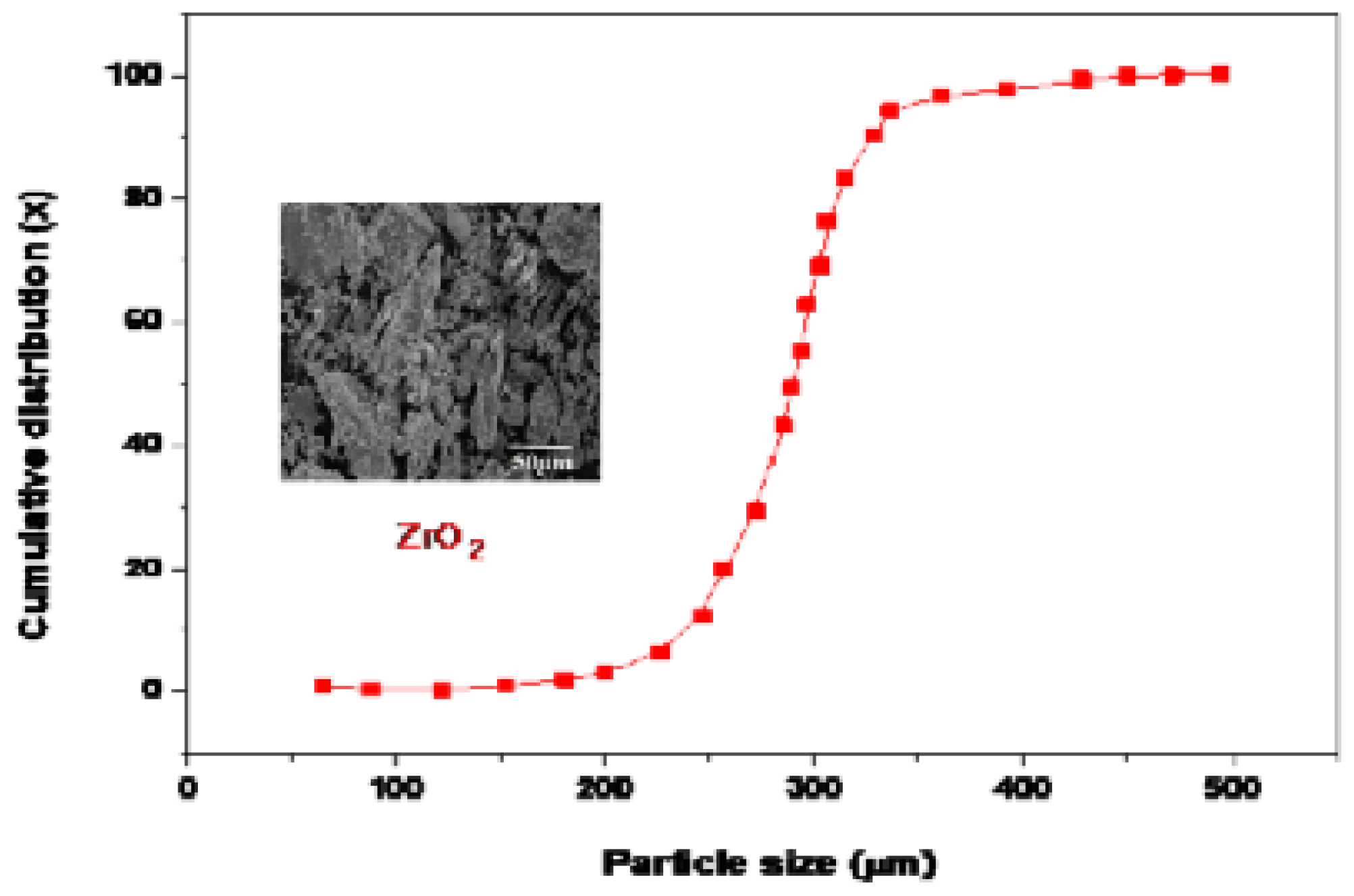
Figure 9.
Optical Electron Microscope (OEM) of (a) AA 6061 (b) 2%B4C (c) 2%B4C / 2%ZrO2/4%SiC (d) 2%B4C /4%ZrO2/8%SiC (e) 2%B4C /8%ZrO2/12%SiC.
Figure 9.
Optical Electron Microscope (OEM) of (a) AA 6061 (b) 2%B4C (c) 2%B4C / 2%ZrO2/4%SiC (d) 2%B4C /4%ZrO2/8%SiC (e) 2%B4C /8%ZrO2/12%SiC.
XRD Analysis
In Figure 10, shows the XRD peak intensities of both AA6061 alloy and hybrid composites. As a result of previous studies are identified Al, B4C and SiC peaks were identified in the XRD [12,13]. From the XRD pattern, it was found that the high peak intensity of Al (111) and Al (200) for all hybrid composites was higher than that of other peaks. According to Scherer equation, the crystalline size was calculated for both AA6061 alloy and hybrid composites. Based on the literature studies, Micro stresses are recognized to significantly rise with shrinking crystal size. The hybrid composites of tensile strength increase with increases of micro tension. As a result of AA6061 were achieved the higher value 42.58 nm, whereas hybrid composites AA6061/2%B4C/8%ZrO2/12%SiC was found to be 28.6 nm, as shown in Figure 11. This decrease in particle size leads to achieving the superior strength of the hybrid composites than pure aluminium AA6061 alloy. Addition of 2%B4C particle-reinforced hybrid composite material with smaller average crystallite size than Al6061 was found to have smaller average crystallite size than 12% SiC reinforced composites. Compared with all proportions of hybrid composites, average crystal size increased with increases SiC concentrations [14].
Compared to stir casting process, other fabrication techniques such as hot extrusion techniques observed that the porosity creation during the sintering process disappeared and the B4C particles distributed themselves predictably in the AA2024 matrix [15].
EDS Analysis
After the stir casting process, EDS analysis was carried out for both pure aluminium alloy and their reinforced composites. When examining SEM micrographs of the pure aluminum alloy, the researchers found that the microstructure rarely contained porosity (Figure 9). By using elemental composition analysis, alloy composition percentages in the structure were also estimated. Different zones of the hybrid material were subjected to elemental (EDS) analyses. The presence of B4C particles can be shown in Figure 12, where the EDS analysis of spectrum 4 shows a significant boron content and high carbon ratio. It is clear from the EDS results from spectrum 4 that this particle is SiC due to its high silicon and carbon composition [16].
From the EDS in Figure 12, examination of the SEM image in Figure 9c shows that cavities have formed around the B4C particles. These are the result of poor wetting properties of the matrix phase and B4C particles. The wettability of aluminum with B4C reinforcement has been shown to be problematic in most of the research.
Figure 13.
EDS analysis of AA6061+2%B4C+4ZrO2+8%SiC alloy.
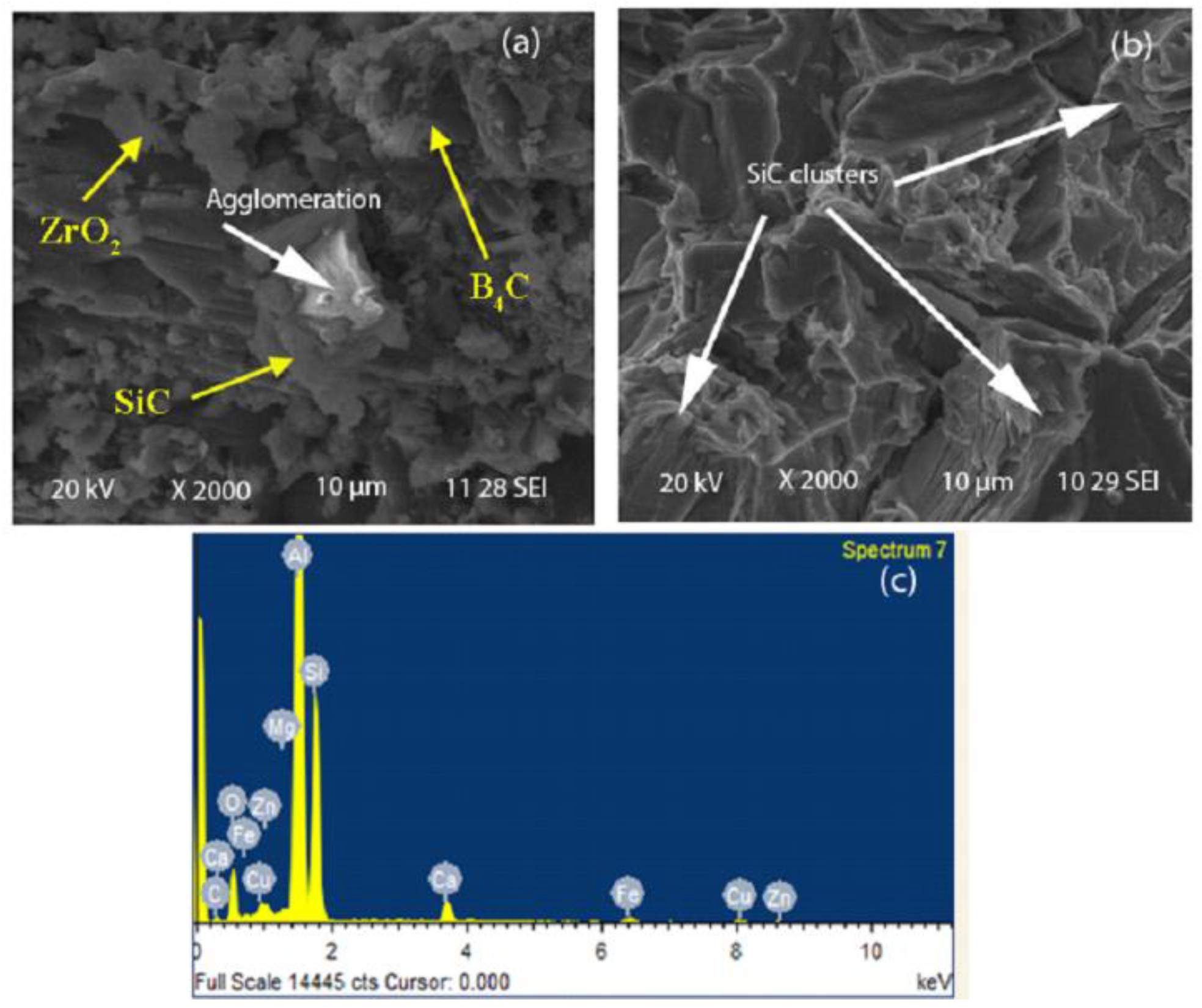
It is clear from the EDS tests from spectrum 4 that this particle is SiC due to its high silicon and carbon content, as shown in Figure 14. The increases of 12% SiC particle on AA6061 matrix leads to form the clustering of particles and agglomeration, which was influenced mechanical properties of hybrid composites. According to the transient contact bond between the matrix AA 6061 and the 12% SiC reinforcement, these defects are detected by the crystallization process.
Fractography Analysis
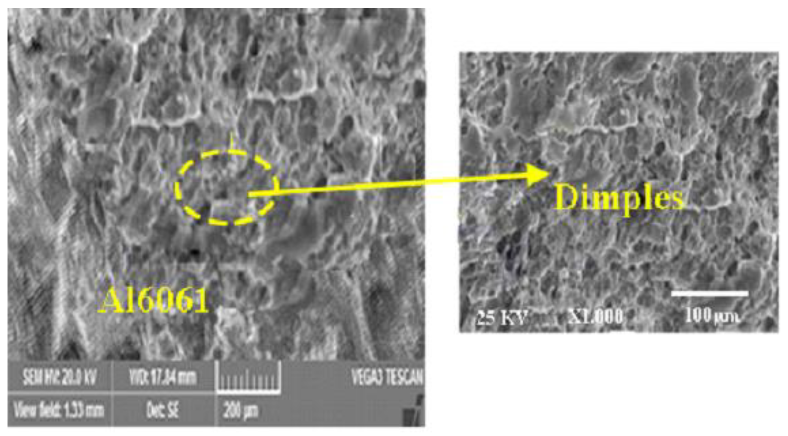
The tensile test was carried out by Universal Testing Machine (UTM) at room temperature. During tensile testing, microstructural studies were carried out to investigate the fracture behaviors and the bonding of the interfaces between the matrices and the reinforcing elements. Samples were taken from complete sections of the fractured surfaces and mounted in SEM to examine the morphologies of the fractured surfaces. SEM observations of the fractured surfaces of Pure Al6061, B4C (2%), ZrO2 (2%, 4%, and 6%) and SiC (4%, 8%, and 12%) hybrid composites were obtained at different magnifications. The superior ductility in the production of pure aluminum matrix preferred hybrid composites leads to micro-perforation on every surface of the fractured material.
Higher quality dimple formation was observed on the fractured surface due to the composition of pure Al6061 material exhibiting higher ductility than the hybrid reinforced composite materials.
Figure 15.
After the tensile test SEM image of the fractured surfaces.
Dimple generation in the fractured regions is increasing by evaluating the compositions of the particles associated with the growth of the boron carbide ratio. This developed from the growth of B4C reinforcement, which makes composite materials more brittle. From the test results, more dimples formation was observed in Al6061-2%B4C-6%ZrO2-12%SiC hybrid composites when compared to pure Al6061 alloys and Al6061+2%B4C reinforcement. As a result of tensile test, 6% of ZrO2 and 12% of SiC reinforcement shows greater tensile strength, indicating high ductility of hybrid composite materials.
Fractured surfaces are separated from the matrix by addition of B4C reinforcement particles. Due to insufficient moisture content, the matrix phase and B4C particles in B4C-reinforced composites have a weak bond. The B4C particles migrate more easily from the matrix and remain on both sides of the fracture surfaces when the material breaks. Furthermore, in SiC-reinforced hybrid composites, it is observed that the SiC particles are incorporated into the matrix phase during tensile due to better adhesion at the interface.
Figure 16 shows the feature of unbroken base alloy interfaces with strong matrix bonding. Micrograph observation demonstrates more ductile fracture in the A16061 alloy, which is mainly composed of SiC particles. Compared to the Al6061 composite, the fractured surface exhibits a decrease in the size of the uniformly distributed particles. The activity of dimples during neck formation in the Al 6061 matrix is visible in the samples prepared at each percentage of hybrids. In hybrid composites including B4C, ZrO2 and SiC, diffusion of reinforcement, residual fragments and tensile zones are clearly observed on these fractured surfaces by Scanning Electron Microscope (SEM).
Figure 17 and Figure 18 shows that no deformation occurs during significant stress transfer between the reinforcement and the matrix. There are some elongated dimples and deformed fragments in the matrix phase, which demonstrates the ductility nature of the hybrid composites. It can be shown through the fracture evaluation and the tensile strength that the addition of SiC particulates has effects over influencing particles. This particular hybrid composites showed indications of dimples, predicted ductile failure and had no fracture after transfer of load, and contained particles that were maintained with dimples. Also, the ductility of the (Al6061/B4C/ZrO2/SiC) hybrids is reduced as a result of the performance of the SiC and ZrO2 particles as a stress concentration element and a propagating crack reducer during load transfer [17].
Conclusion
- Using a stir casting approach to examine the Al6061 microstructure and found that there were no pores in the hybrid composites (AA6061+B4C/ZrO2/SiC). The study discovered that the microstructures of the B4C/SiC-reinforced composites typically showed a homogeneous dispersion of ZrO2/SiC particles inside the matrix of 6%ZrO2+12%SiC composites.
- Agglomeration increased simultaneously with increase in B4C in 2%B4C and pure AA6061 compositions. Less porosity was observed in the 12%SiC hybrids, although they exhibited a higher degree of aggregation than the micro-structure when compared to the other composites.
- The Scherrer equation was used to determine the crystal size. As a result, AA6061 had a larger crystal size of 42.58 nm as opposed to the hybrid composites of AA6061/2%B4C/8%ZrO2/12%SiC, which had a crystal size of 28.6 nm.
References
- S. Muzeer, S. Sivaganesan (2022), “Tribological behaviour of aluminium based hybrid metal matrix composites (Al6061/B4C/ZrO2/SiC)”, Materials Today Proceedings”, Volume 56, Part 1, 2022, Pages 507-513.
- Hanumanth GS, Irons GA. Particle incorporation by melt stirring for the production of metal-matrix composites. J Mater Sci 1993; 28:2459–65. [CrossRef]
- Surappa MK. Aluminium matrix composites: challenges and opportunities. Sadhana 2003;28(1–2):319–34. [CrossRef]
- Macke A, Schultz BF, Rohatgi P. Metal matrix composites offer the automotive industry an opportunity to reduce vehicle weight, improve performance. Adv Mater Processes 2012;170(3):19–23.
- Christy TV, Murugan N, Kumar S. A comparative study on the microstructures and mechanical properties of Al 6061 alloy and the MMC Al 6061/TiB2/12p. J Miner Mater Charact Eng 2010;9:57–65.
- Miracle DB. Metal matrix composites-from science to technological significance. Compos Sci Technol 2005; 65:526–40.
- Prabu SB, Karanamoorty L, Kathiresan S, Mohan B. Influence of stirring speed and stirring time on distribution of particulates in cast metal matrix composite. J Mater Process Technol 2006; 171:268–73.
- Miracle DB. Metal matrix composites-from science to technological significance. Compos Sci Technol 2005; 65:526–40. [CrossRef]
- 9Kumar S, Vasumathi M. Applying visualization techniques to study the fluid flow pattern and the particle distribution in the casting of metal matrix composites. J Manufact Proc 2020; 58:668-76.
- Velavan K, Palanikumar K, Natarajan E, Lim WH. Implications on the influence of mica on the mechanical properties of cast hybrid (Alþ 10% B4Cþ Mica) metal matrix composite. J Mater Res Technol 2021; 10:99-109.
- S. Muzeer, S. Sivaganesan (2022), “Wear Optimization of Aluminium and Hybrid Reinforcement Metal Matrix Composites Using Response Surface Methodology”, Materials Science Forum (Volume 1073), 37-48. [CrossRef]
- Yuvaraj N, Aravindan S, Vipin. Fabrication of Al5083/B 4 C surface composite by friction stir processing and its tribological characterization. J Mater Res Technol 2015; 4:398–410,.
- Sambathkumar M, Navaneetha Krishnan P, Ponappa KSKS. Mechanical and Corrosion Behavior of Al7075 (Hybrid) Metal Matrix Composites by Two Step Stir Casting Process. Lat Am J Solids Struct 2016; 7075:243–55. [CrossRef]
- Maniammal K, Madhu G, Biju V. X-ray diffraction line profile analysis of nanostructured nickel oxide: Shape factor and convolution of crystallite size and microstrain contributions. [CrossRef]
- Zheng R, Hao X, Yuan Y, Wang Z, Ameyama K, Ma C. Effect of high-volume fraction of B4C particles on the microstructure and mechanical properties of aluminum alloy-based composites. J Alloys Compd 2013. [CrossRef]
- Dhas, DSEJ, Velmurugan, C, Wins, KLD2018, ‘Investigations on the effect of tungsten carbide and graphite reinforcements during spark erosion machining of aluminium alloy (AA5052) hybrid composite’. Silicon’, vol 10, no.6, pp. 2769-2781, ISSN: 1876-9918. [CrossRef]
- Amirkhan Lou S & Niroumand B. 2011, Development of Al356/SiCp cast composites by injection of SiCp containing composite powders Mater Des’, vol. 32, no.4 pp. 1895-1902, ISSN: 0264-1275.
Figure 10.
XRD pattern of AA6061 and hybrid composites.
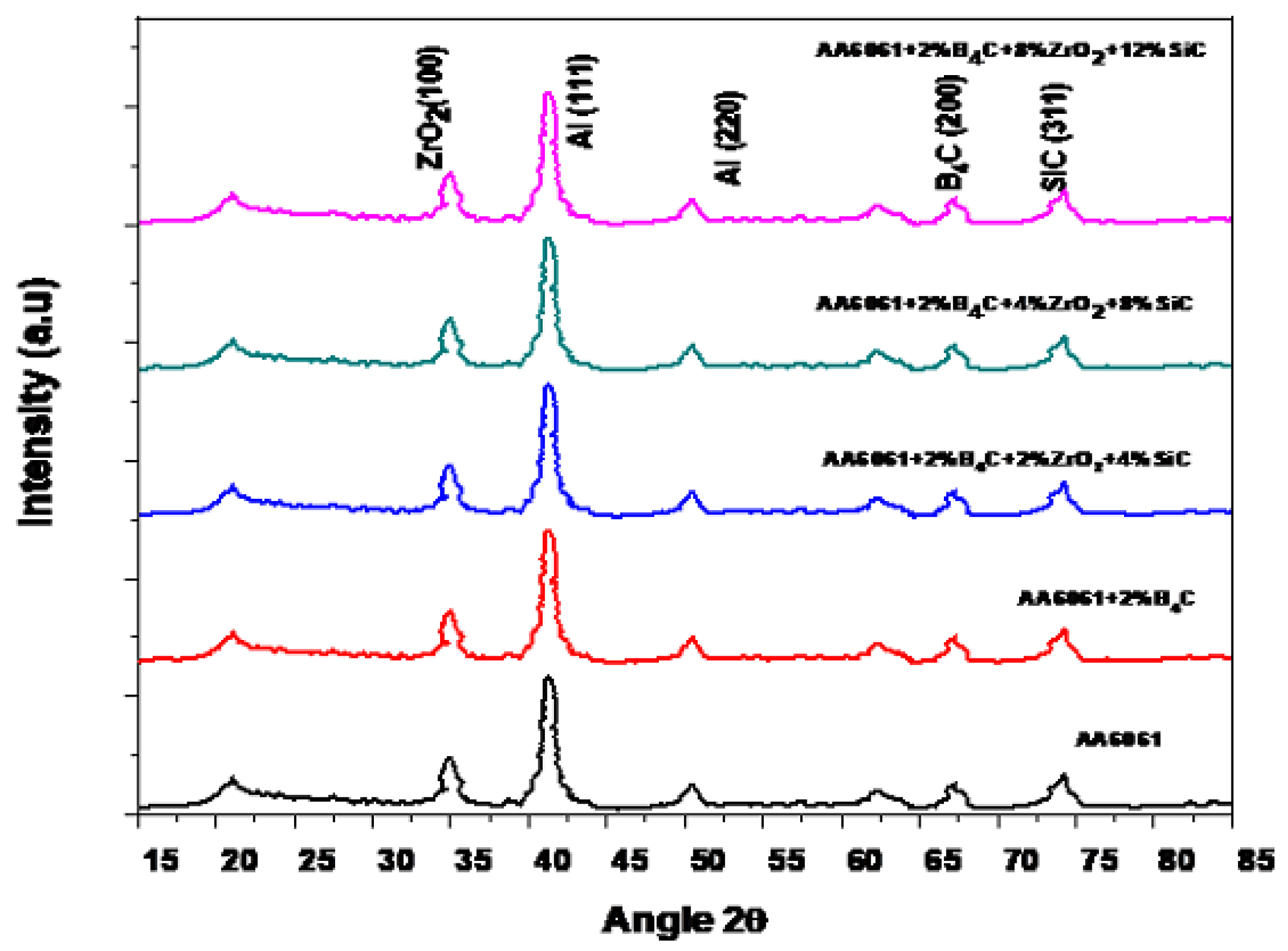
Figure 11.
Average crystal size nm.
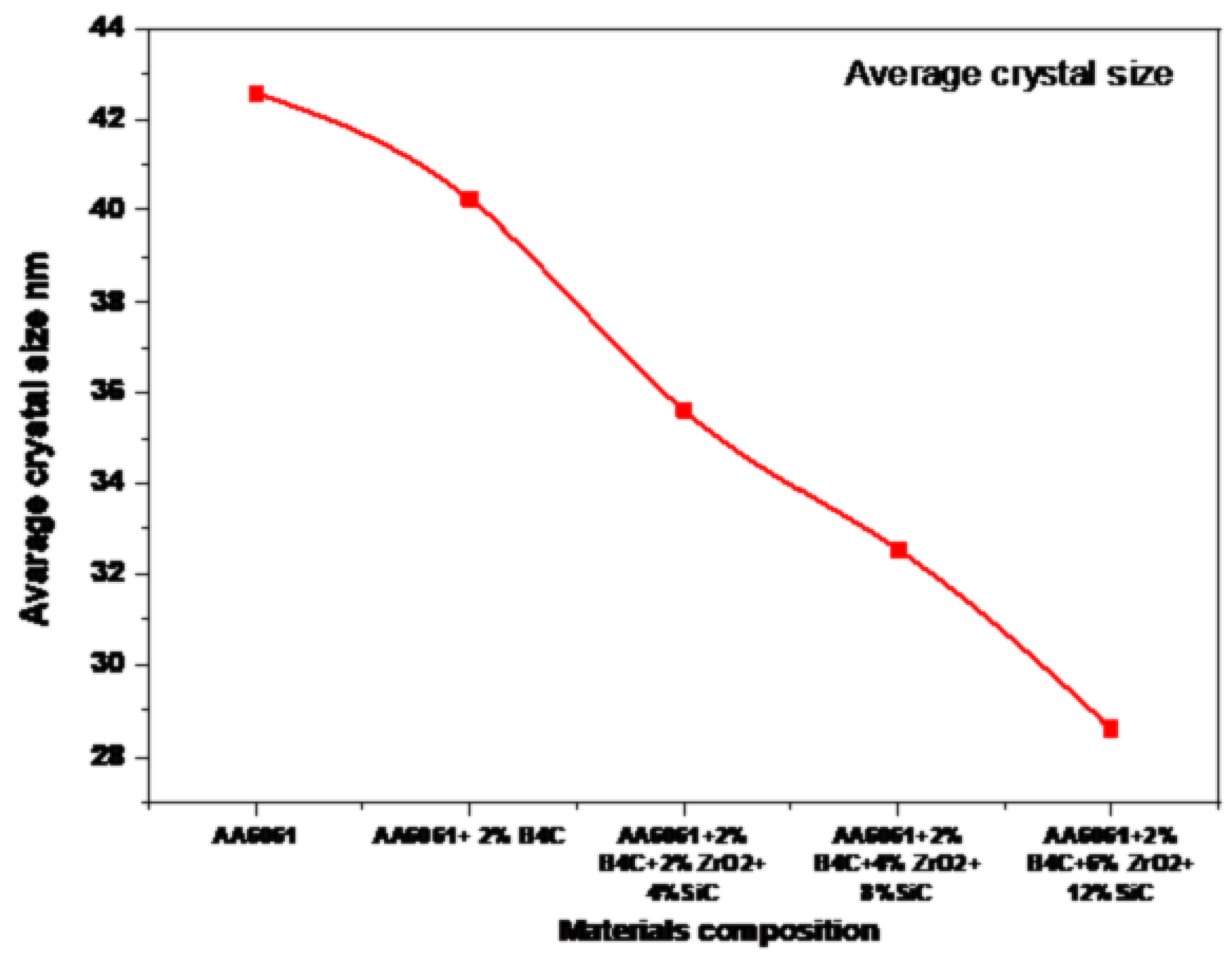
Figure 12.
EDS analysis of AA6061 alloy.
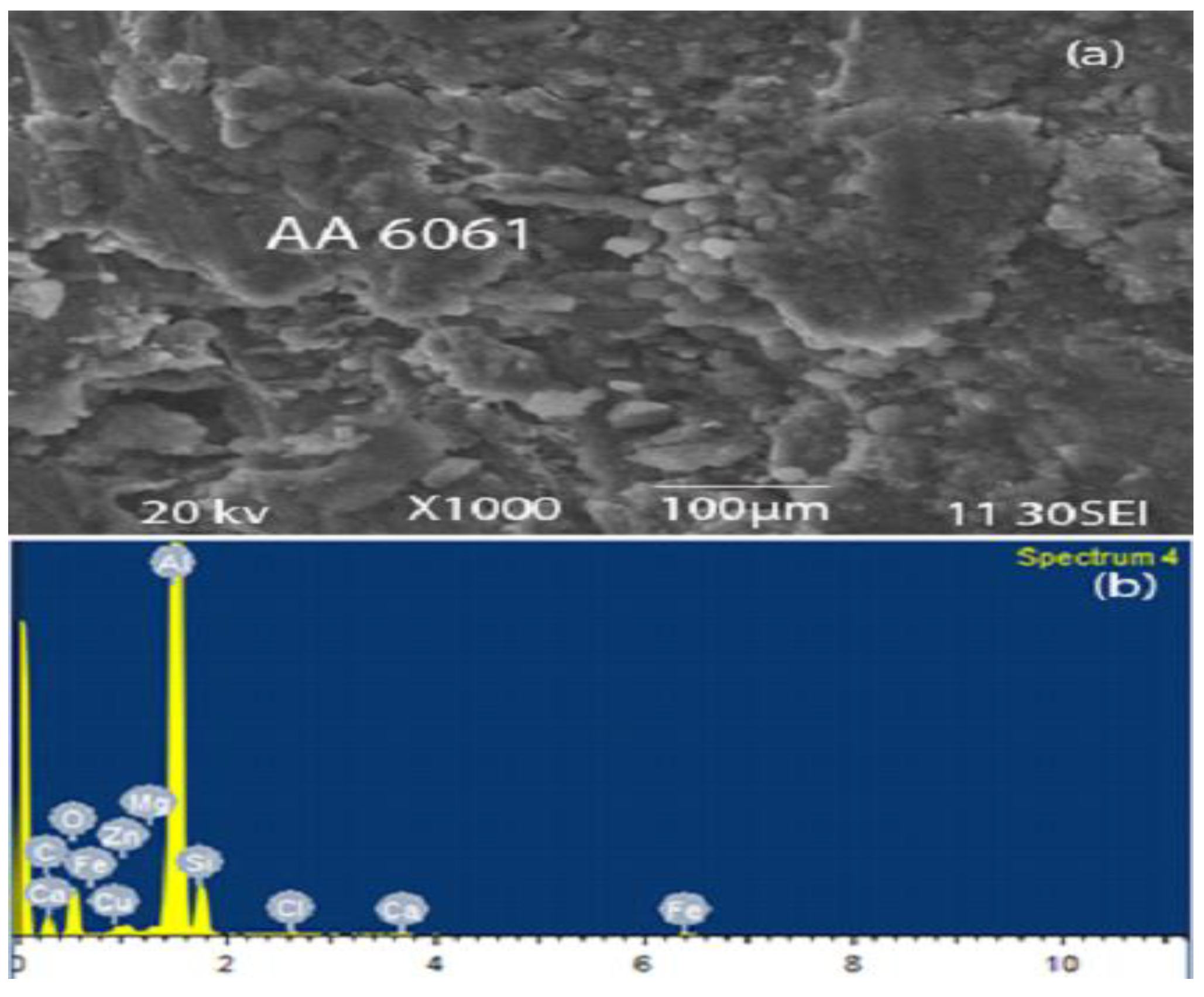
Figure 14.
EDS analysis of AA6061+2%B4C+6ZrO2+12%SiC alloy.
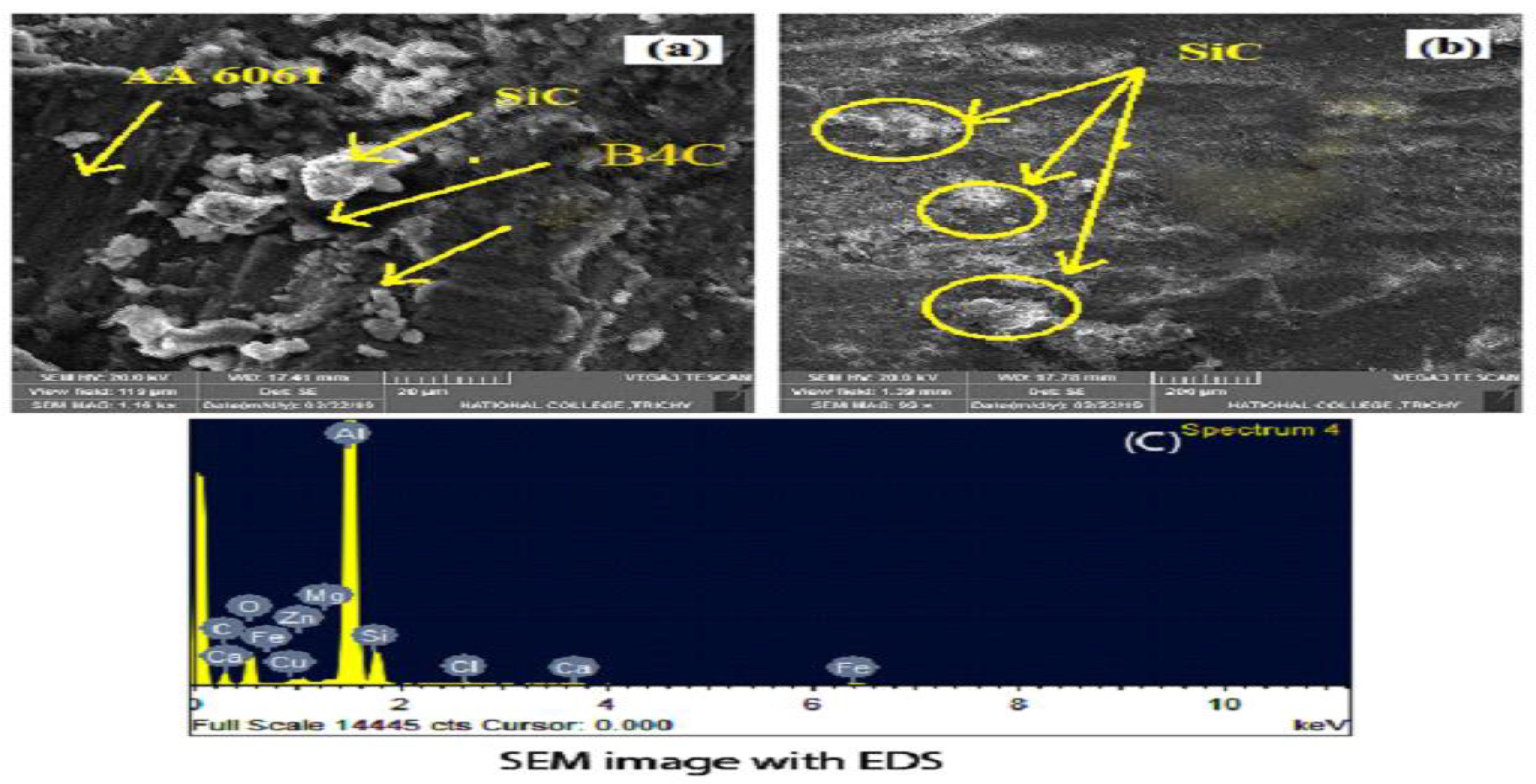
Figure 16.
SEM image of hybrid composites (AA6061+2%B4C+6%ZrO2+12%SiC).
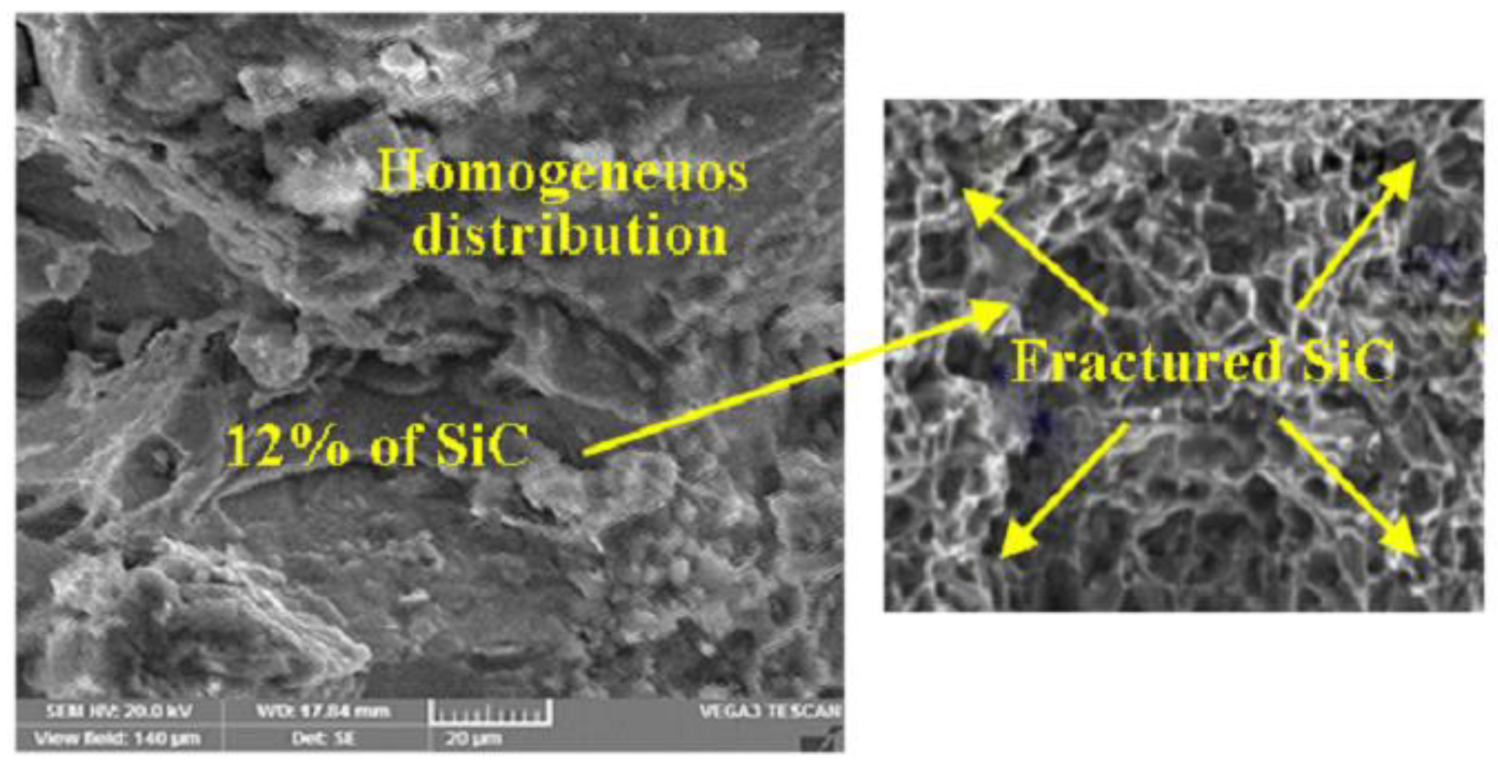
Figure 17.
SEM image of Debonded Interface after tensile test.
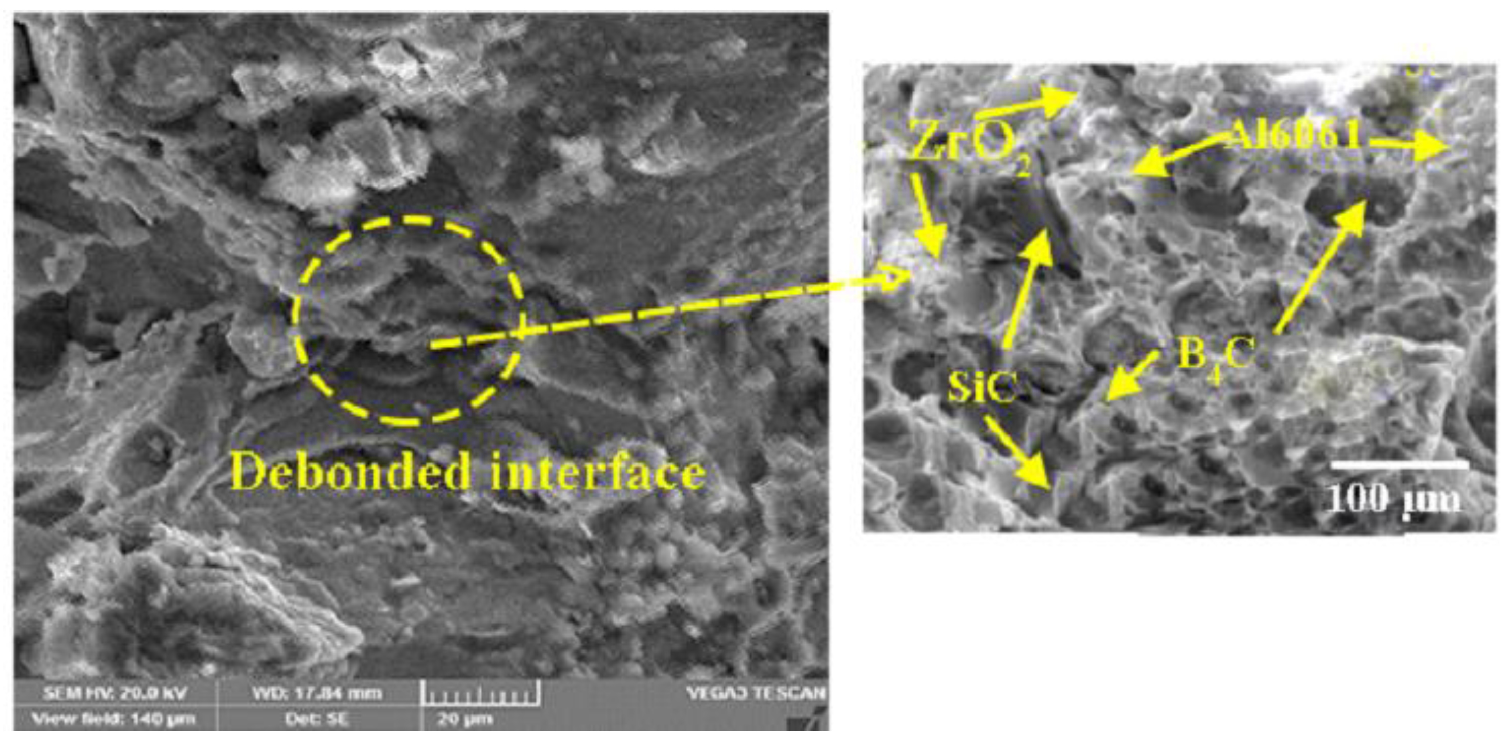
Figure 18.
SEM image of Cracked B4C particles during the tensile test (Al6061+2%B4C).
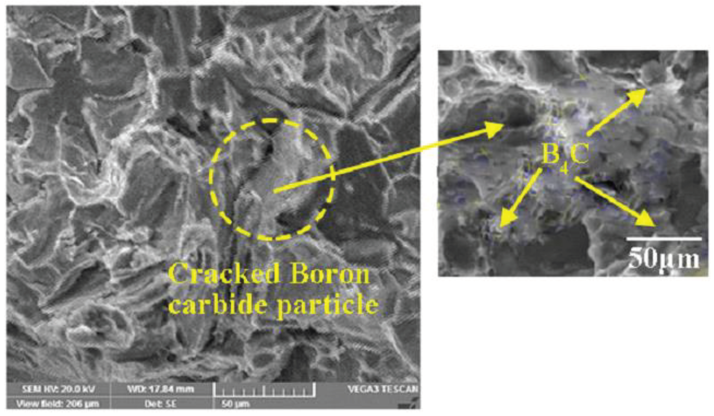
Table 8.
Hybrid composite mixtures.
| S.No | Composition | AA6061 | B4C | ZrO2 | SiC |
| g | g | g | g | ||
| 1 | Al6061 | 1500 | 0 | 0 | 0 |
| 2 | Al6061+2%B4C | 1470 | 30 | 0 | 0 |
| 3 | Al6061+2% B4C +2%ZrO2+ 4%SiC | 1380 | 30 | 30 | 60 |
| 4 | Al6061+2% B4C +4%ZrO2+ 8%SiC | 1290 | 30 | 60 | 120 |
| 5 | Al6061+2% B4C +6%ZrO2+ 12%SiC | 1200 | 30 | 90 | 180 |
Disclaimer/Publisher’s Note: The statements, opinions and data contained in all publications are solely those of the individual author(s) and contributor(s) and not of MDPI and/or the editor(s). MDPI and/or the editor(s) disclaim responsibility for any injury to people or property resulting from any ideas, methods, instructions or products referred to in the content. |
© 2024 by the authors. Licensee MDPI, Basel, Switzerland. This article is an open access article distributed under the terms and conditions of the Creative Commons Attribution (CC BY) license (https://creativecommons.org/licenses/by/4.0/).
Copyright: This open access article is published under a Creative Commons CC BY 4.0 license, which permit the free download, distribution, and reuse, provided that the author and preprint are cited in any reuse.


