Preprint
Article

Design of a Transtibial Prosthetic Pylon Using Auxetic Metamaterials: Simulation and Experimental Validation

Altmetrics

Downloads

178

Views

84

Comments

0

Submitted:

13 February 2024

Posted:

13 February 2024

You are already at the latest version

Alerts
Abstract
Prosthetic device is designed to function as a replacement for a missing limb and typically consists of suspension, liner, socket, pylon and foot components. The objectives of this research are to design a pylon component of a transtibial prosthetics by implementing auxetic metamaterial and to also validate performance of the designed pylon under quasi-static and dynamic conditions. The design and analysis processes are conducted using the finite element analysis and its effectiveness is validated by experimental testing of the prototype pylon sample. In the design process, the pylon structure is formulated by rearranging 2D re-entrant hexagon model into 3D model. It is identified from the design evaluation that the pylon exhibits the stiffness of the value of 79.24, 2371.6, and 13344 kN/m for the ligament thickness variation of 0.3 mm, 1 mm, and 2 mm, respectively. This directly indicates a capability of the stiffness tuning of the pylon by changing the ligament thickness. It is evaluated that the pylon with the ligament thickness of 0.3 mm causes the deformation of 0.53 cm during a single period of gait cycle, while the ligament thickness of the 1 mm causes the deformation of 0.4 cm. The deformation physically indicates the energy absorption of the pylon structure and hence the thinner ligament, the higher energy absorption provides. It is also found from the deformation transition of the primary and secondary bends, the negative Poisson’s ratio is occurred in 3D model transformed from 2D re-entrant hexagon.
Keywords: 
Subject: Public Health and Healthcare  -   Public Health and Health Services

1. Introduction

Prosthet-ics are very effective devices which could replace a missing or disarticulated body part [1]. Recently, the development of the prosthetic has a trend of applying control systems to provide active or semi-active behaviors such as the use of motors and magnetorheological (MR) dampers [2,3]. Active system may provide in-use control with appropriate sensor and actua-tor settings. The semi-active MR damper with its unique behavior might be potential to be used in prosthetic design, especial-ly for impact loading condition or variable stiffness (achieved through controlling its flow resistance by the magnetic field) as shown in studies [4,5]. Such a system, although beneficial for its intended function, would require on-site power [6] and could also increase the cost of maintenance and the prosthetic itself. While on the other hand, auxetic metamaterials have the potential to be fine-tuned for a particular function in a purely mechanical system. For this purely mechanical system, component and sub-system like spring [7], or similarly behaving part [8] works as an actuator by storing input ener-gy for a period of time before releasing it as the input force recede. A four-bar linkage mechanism has also been shown to pro-vi-de a certain degree of motion to the prosthetic [9]. A more advanced design utilizes the foot part itself to provide the necessary energy storing and release and such design is known as energy storing and return (ESAR) [10]. For this type of design, carbon fiber has been frequently chosen as the material due to its lightweight and strength related properties. The use of carbon fiber however causes a fluctuation in terms of manufacturing cost resulting in the increment of the market price, making this design less accessible to the general population. As an actuator for a prosthetic, an auxetic metamaterial has yet to be developed. There has been some form of implementa-tion of auxetic metamaterial as mechanical energy absorption for the foot part of a prosthetic. Other research focused on provid-ing improved comfort for users by providing auxetic metamaterials on the surface of the socket (interface part) for lower limb prosthetics [11]. Neither of these two types of research implements auxetic metamaterial as an actuator, rather more akin to a mechanical damper for dissipating mechanical energy. This gap is a potential for auxetic metamaterial to be used as actuators for prosthetics, specifically in terms of energy storage and return due to the unnatural deformation behavior it exhibits. It might be possible to replace the spring with auxetic metamaterial, seeing as the spring itself shows close to zero Poisson’s ratio (more likely to deform in the axial direction compared to the lateral direction). As well known, the metamaterial is a class of artificial material with unique properties that combines its inherent material properties and the structure’s design [12]. The combined properties would not be commonly found in natural materials (with few exceptions such as negative Poisson’s ratio in biomaterial [13]). Metamaterials could then be classified depending on the unique properties exhibiting optical (negative refraction index) [14], electromagnetic (negative permittivity) [15], thermal (negative thermal expansion) [16], acoustic (soundwave absorption) [17], and mechanical metamaterial showing the properties of negative Poisson’s ratio in which it defines the negative ratio between lateral strain and axial strain [18]. Naturally occur-ring materials are likely to have a positive Poisson’s ratio value, contributed by the tendency of thinning under tensile and expanding in a lateral direction under compression. In comparison, an auxetic metamaterial made from the same inherent material would have the tendency to expand under tensile and contract inward under compression [19]. Auxetic metamateri-al has been proposed and discussed to be beneficial in protective devices [20], robotics [21], and medical field [22] developments. The development of auxetic metamaterials is generally divided into three categories. The first and most common is developing a novel structure [23], improving certain aspects of already developed structures, such as increasing stiffness [24]. Secondly, there is also research specifically done to improve the quality of fabricating auxetic metamaterials [25]. The third categories are the research aimed at applying auxetic metamaterial to the functioning tool, for instance, the implementa-tion of a honeycomb sandwich panel to improve ballistic protections [26], and the implementation on the foot part of lower limb prosthetic [27].
De-spite several works on the rehabilitation field using the auxetic metamaterials, an experimental validation study of the effective-ness of the designed device is considerably rare. Therefore, the main technical contribution of this work is to design a transtibi-al prosthetics utilizing auxetic metamaterials and validate the beneficial effect of the proposed approach through an experi-men-tal investigation. In the design process, the finite element analysis (FEA) is adopted to resolve certain difficulties related to the lack of accurate constitutive models of metamaterials as well as design complexity. The use of FEA is one of potential solutions to study the behavior of auxetic metamaterial for the development of novel geometries or even for understanding the performance of application devices or systems. And in order to handle the fabrication difficulties, additive manufactur-ing (AM) method [28] is used by integrating fused deposition modeling (FDM) [28]. It is noted here that AM method is partial-ly effective to fabricate the structures such as flexible behavior of auxetic metamaterials [29]. However, this problem can be investigated by experimental testing and some geometrical values are achieved from the FEA. As mentioned, the specific aim of this work is to implement auxetic metamaterials as actuators for a new type of a transtibial prosthetic. The design and analysis are carried out by FEA and then its effectiveness is validated through experimental testing. Considering energy absorption capabilities, the performance comparison between conventional spring and auxetic metamaterial is al-so discussed. It would then be closed with a judgment regarding the practical feasibility of using auxetic metamaterial as an actuator for the manufacturing of the transtibial prosthetics and other rehabilitation devices or systems.

2. Materials and Methods

2.1. Pylon Design

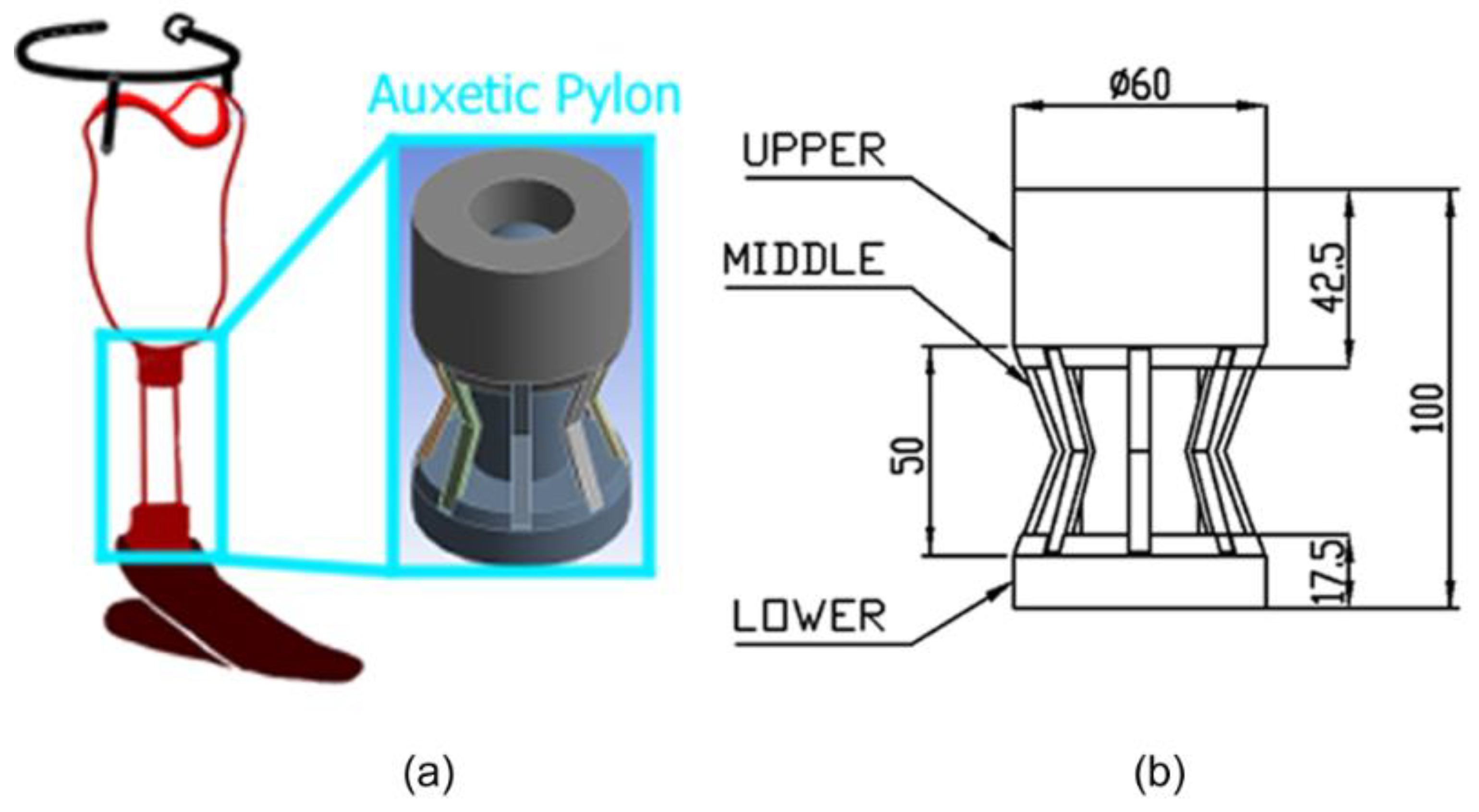
The geometries of the auxetic metamaterial are shown in Figure 1. The first design (Figure 1(a)) is based on a planar (2D) re-entrant hexagon that is reoriented as a 3D structure by radially patterning each ligament similar to a pillar. The second structure is based on a 3D re-entrant hexagon studied in [30] This structure was shown to exhibit a negative Poisson’s ratio in all principal directions (structure shown in Figure 1(B)). Inspired by this modification, by slightly modifying the structure orientation of the original re-entrant hexagon into a radial 3D array is shown in Figure 1 (C). Based on a design of transtibial prosthetics, the conventional pylon is made up as a simple cylinder meant to stay rigid through its usage. This type of pylon would provide minimum amount of energy absorption due to its stiffness. To overcome this issue, by applying the proposed auxetic structure (Figure 1 (c)), a novel design for an auxetic metamaterial-based pylon is used in this work to replace the conventional pylon illustrated in Figure 2 (a). The pylon design, as shown in Figure 2 (b), com-prised three parts, with a total length of 100 mm. The design is based on the assumption of a standard Below Knee Amputa-tion (BKA), where 50% of the original limb length (assumed to be 200 mm) is amputated. The upper part works as the connec-tion between the pylon itself and the socket. A connection or joint might be included in further design, but the socket is not modeled initially considering the need for flat surface for experimental testing procedure. Along with the socket, this part also acts to keep the middle stays inline by providing a set of slots to insert the ligaments of middle part. The middle part function as the main weight bearing and connection within the pylon, it is also the part designed to accommodate the auxetic structure mentioned earlier. It consists of eight ligament bend at certain angle to be inserted between the upper and lower components. Lower part follows the design principle of the upper part by providing a matching set of slots with the same function. Other than that, it is also designed with a shaft to limit the deformation of ligaments as to prevent collapse of the system under excessive weight, and a ball is also designed on top of the shaft to match the diameter of the hole on the upper part keeping the system inline during usage.
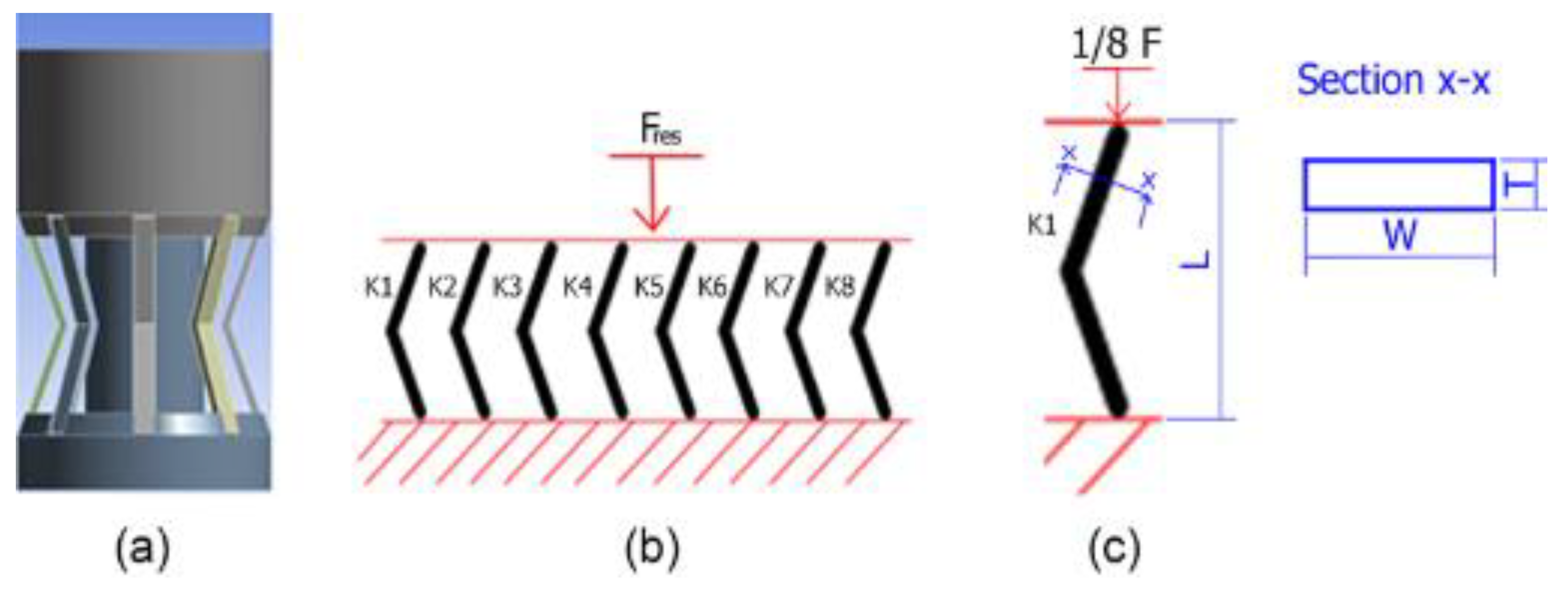
Based on the proposed design, it could be analogized as a simple spring system with single degree of freedom in which each ligament compromising the middle component operates as the spring unit as a model shown in Figure 3(a) and further simplified in Figure 3(b). For this system, Hooke’s law regarding the relationship of stress (σ) and strain (ε) towards the value of Young’s modulus (E) are in effect, written as
E = σ ε
Rearranging the equation to solve the strain as follows.
ε = σ E
Stress is comprised of force (F) over cross-sectional area (A), which could be quantified as thickness (T) times width (W) of each ligament (illustrated in Figure 3(c)) As there are eight ligaments the cross-sectional area is multiplied accordingly as follows.
σ = F A ,
σ = F ( 8 T   W ) ,
While the strain component could also be defined with a relation between original pylon length (L) and its deformation (ΔL) as
ε = Δ L L
By substituting the above Eq. (4) and Eq. (5) into Eq. (2) yields the following.
Δ L L = F ( 8 T   W ) E .
Hooke’ law also dictates the relation between stiffness coefficient of system (Kres) with force (F) and length deformation as
F = K res . L ,
L = F K res   ,
Substituting the above equation in Eq. (4) yields
F K res L = F ( 8 T   W ) E
By solving the equation, the stiffness of system could be written as
K res = E   ( 8 T   W ) L
based on earlier assumption that each ligament works as separate springs in parallel arrangement, the value of Kres could be defined by substituting individual stiffness coefficient of each ligament, as
K res = K 1 + K 2 + K 3 + K 4 + K 5 + K 6 + K 7 + K 8
Every ligament is designed with the same geometry and materials, and the value of each and every stiffness could be assumed as equals, or written as
K 1 = K 2 = K 3 = K 4 = K 5 = K 6 = K 7 = K 8 = K s i n g l e
Based on this, the stiffness coefficient of individual ligament (Ksingle) could also be calculated as follows.
K res = 8 K sin gle
K sin gle = 1 8 K res

2.2. Material Consideration

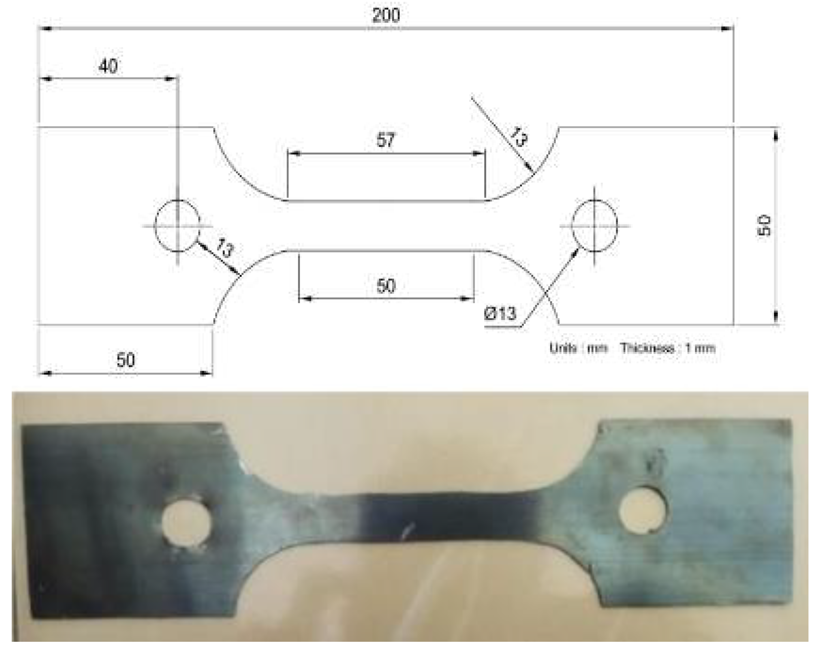
Based on assumption that the ligaments on the middle part operate with the principle, similar to spring, the material would need to be chosen accordingly. For this purpose, a high carbon steel denoted SK5 spring steel is chosen as the material for the ligaments. Meanwhile, the upper and lower part are designed to be made from PLA (Polylactic Acid) considering its lightweight and ease of manufacturing owing to the advancement of AM (additive manufacturing) technology such as FDM (Fused Deposition Modeling). PLA filaments are manufactured using Creality Ender 3 with infill of 30% [31]. The infill density is chosen to maintain some form of strength while also not losing its lightweight properties. PLA mechanical properties are shown in Table 1. To model the correct behavior of SK5 spring steel given in Table 2, a tensile test is conducted based on ASTM E8 standard using the pin-loaded specimen shape with the scheme and photograph shown in Figure 4 and the results displayed in Figure 5 in terms of force-displacement (left) and stress-strain (right).

2.3. Experimental Validation

The results achieved from the finite element analysis (FEA) done within this research are experimentally validated by testing sample prototype under equal condition of 4 mm vertical displacement. The fabrication process of the prototype is divided into three phases: fabricating upper and lower part, fabricating the middle part, and assembling the pylon together. During the 3D printing of upper and lower parts, the models are first made and then converted into Standard Tessellation Language (STL) for slicing process in ultimaker cura 5.3. Printed parts would then be inspected for defect and fitting with each other. Minor fitting mismatch such as rough surface would need to be rectified by sanding the components. A smooth sliding condition between inner side of upper hole and the ball of lower shaft must be thoroughly verified as to prevent its roughness affecting the experimental behavior of ligaments. The ligaments for the middle part are made by cutting a rectangular pattern on 0.3 mm, 1 mm, and 2 mm of SK5 spring steel plates, respectively. The varying thickness can provide a comparison between different stiffness. Pieces that have already been cut would then need to be bend at 40° in the middle. Bended piece would act as then act as the ligaments for the pylon.
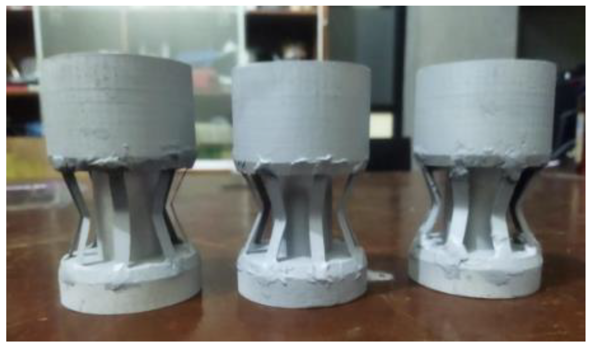
Assembling process is done by inserting the shaft of lower part to be inline with the hole of upper part. The ligaments are then inserted into the slots of upper and bottom part for each end of ligament. To fix all the ligaments in place, plastic steel is spread over the slots as adhesive. Figure 6 displays the photograph of prototype fabricated following the mentioned process. During the designing process, several assembling or joining mechanism has been considered; one such consideration includes welding the middle ligaments with upper and lower parts similar to how a car chassis consisted of several tube (similar to ligaments in this case) are welded together to form its structure [32]. This design, however, would cost more weight to the overall pylon. As long as neither the PLA printed upper and lower along with its adhesive with middle ligaments fails, then welding it might not be required.

2.4. Simulation Procedure

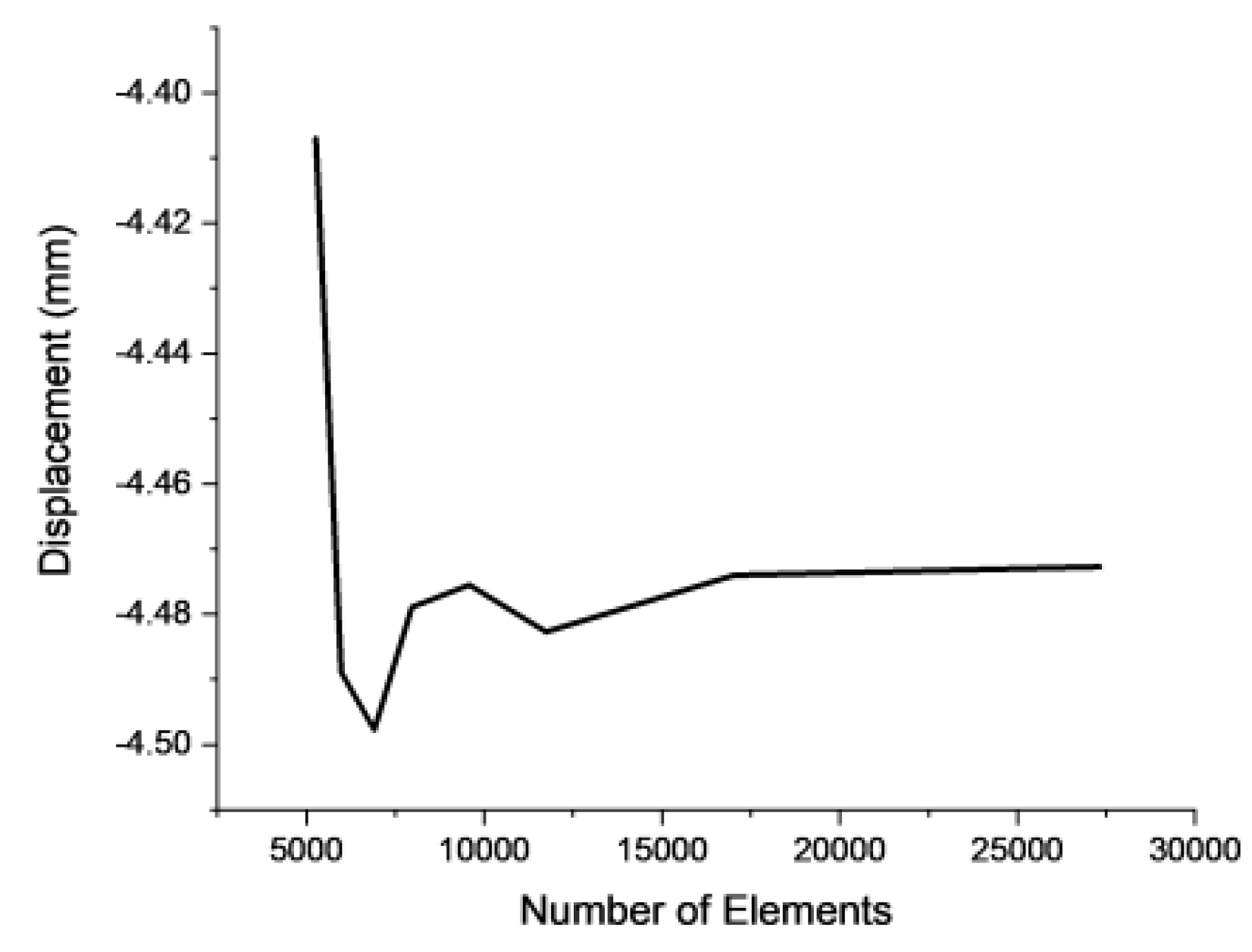
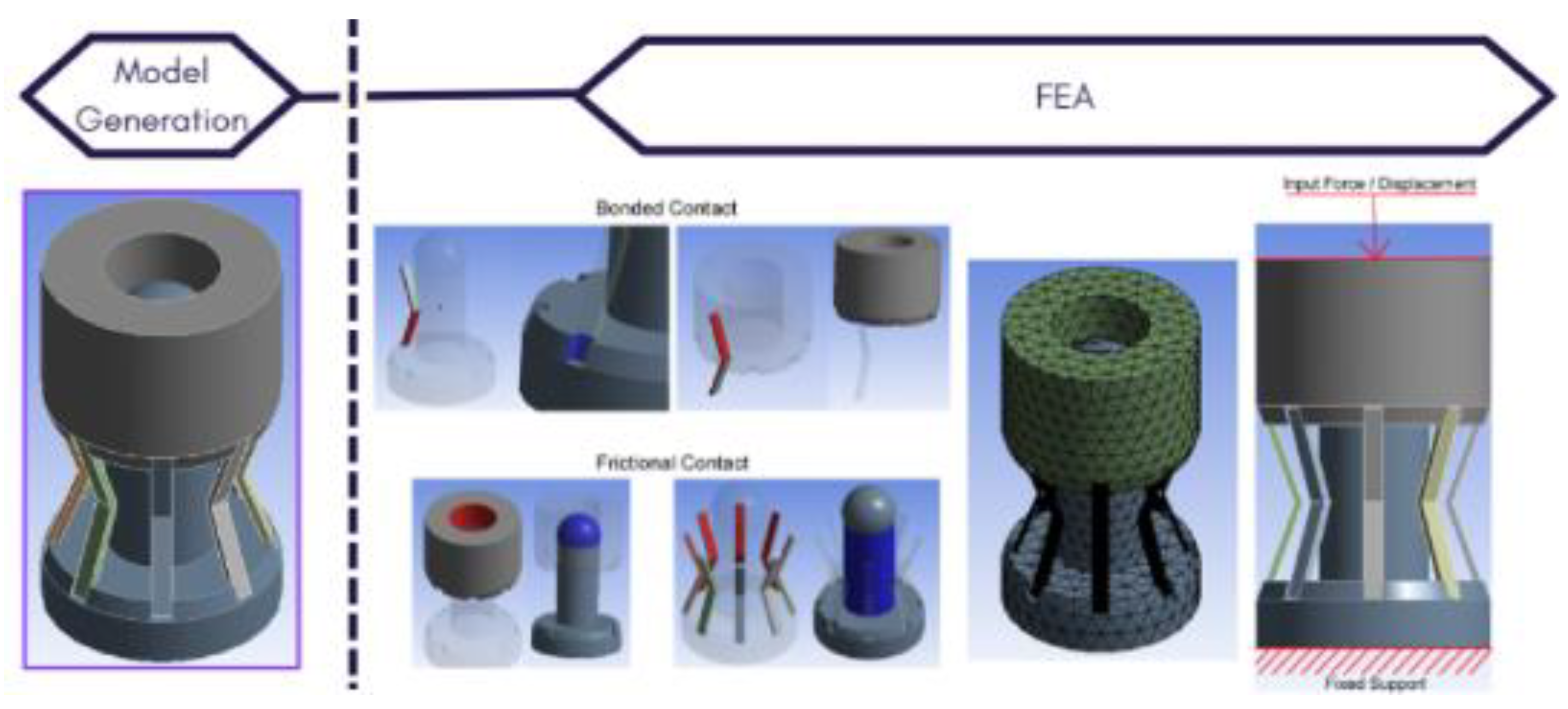
Geometrical models are first generated and then exported as Initial Graphics Exchange Specification (IGES) file to be transferred in ANSYS workbench. Contact definition of each part within pylon assembly is defined based on type of connection as fabricated for the prototype. The fixed connection of ligaments and upper and lower parts are modeled as bonded connection to define a permanent connection between its surfaces. Meanwhile, the contact between inner face of ligaments and surface of lower shaft along with the connection of upper hole and lower shaft are defined with 0.2 frictional contact coefficient. Following the contact definition, the model would need to be meshed. Considering the priority of focusing on the behavior of middle part compared to the other part, while also limiting the computational burden, a rather coarse value for upper and lower mesh elements are chosen by 6 mm. In comparison, considering the need for accurate modeling of the behavior for the middle part, a mesh convergency analysis is conducted by varying the mesh element size with identical model (0.3 thickness variation), boundary condition (force load of 686.6 N) and tracking its maximum displacement in vertical direction starting with coarse value of 1 mm and getting smoother until stabilizing at 0.3 mm element size as shown in Table 3 and compared in Figure 7. Based on the mesh convergency analysis, the resulting maximum vertical displacement stabilize at element size 0.3 mm as shown by minimum difference compared to the 0.4 mm of element size. General boundary condition for each simulation could be defined as fixing the bottom surface of lower part, limiting the displacement on X and Z axis for the upper part, and defining the load on the top surface of upper part. The complete simulation procedure containing the contact definition, meshing, and boundary condition are illustrated in Figure 8

2.5. Case Definition

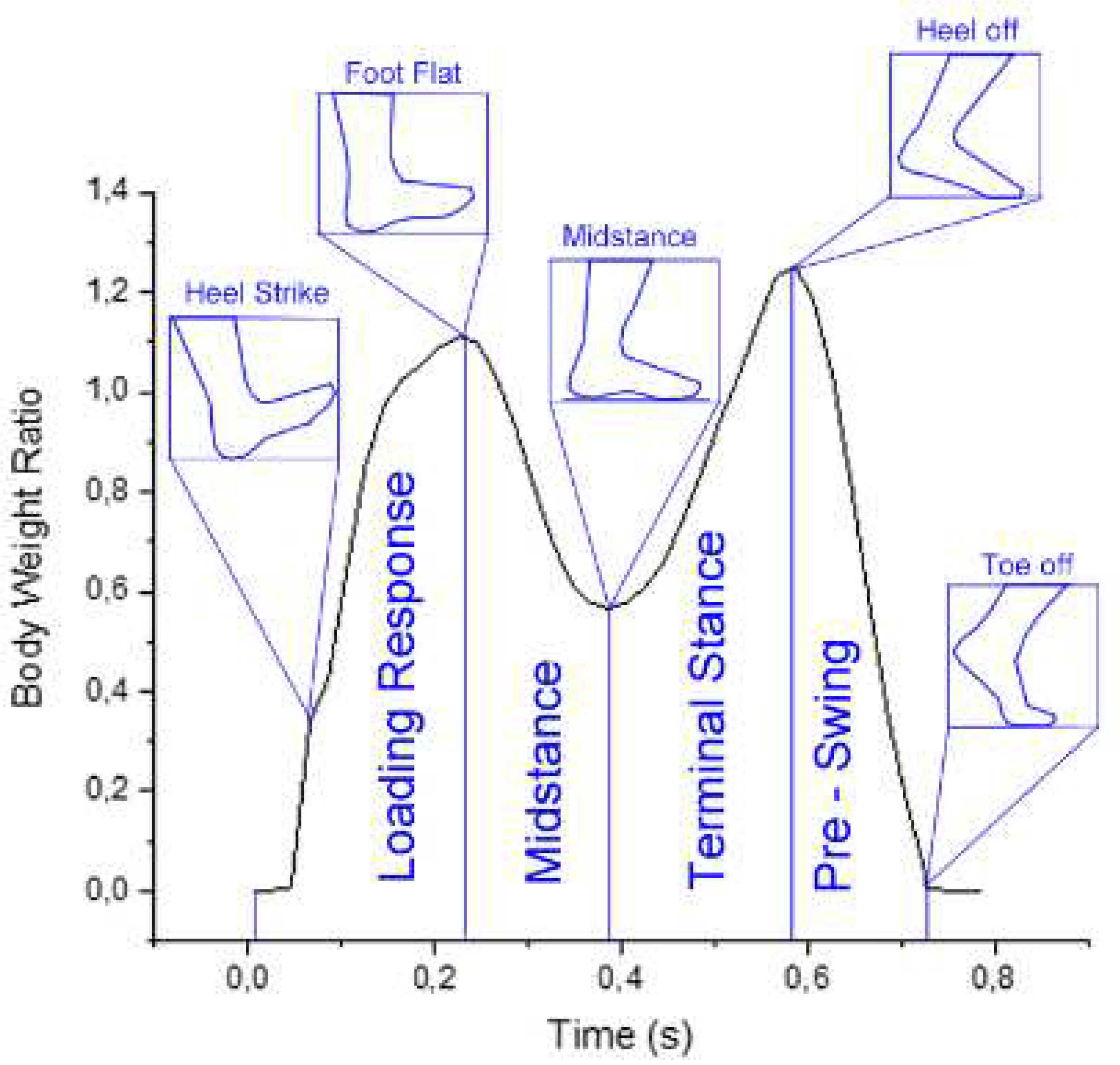
Two usage conditions for pylon are simulated to analyze the behavior and performance of the pylon during body weight bearing and during gait condition. For body weight bearing, a load based on assumption regarding patient body weight is defined on top of upper part at 70 Kg or about 686.6 N. The weight is simulated in quasi-static condition with linear loading. Meanwhile, the gait simulation condition is based on experimental condition tracking the ground reaction force of 5 patient sample over time with walking rate of 1.58 m/s [33] as shown in Figure 9. The gait is divided into four stages: the loading response, midstance, terminal swing, and pre-swing.

3. Results & Discussion

3.1. Experimental validation

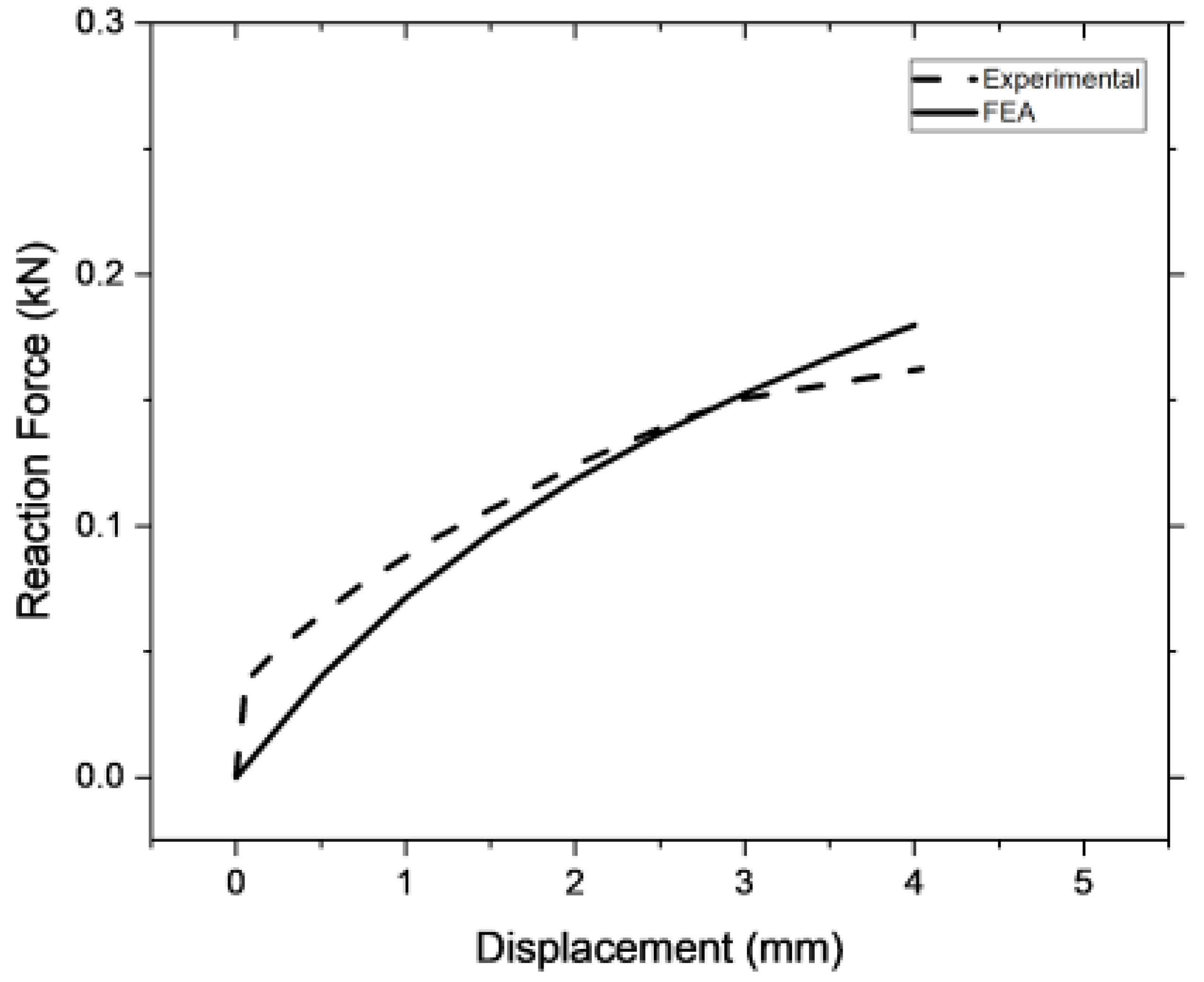
Experimental testing along with equivalent simulation process has been conducted with the results shown in Figure 10. The results are compared in terms of reaction force over displacement. To quantify the difference in value, the error between simulation and experimental result could be calculated as
Error = X - exp X - FEA X - exp
where X - exp is the mean value of reaction force for experimental testing and X - FEA for the simulation result. Based on this equation, the error between the two values is calculated as follows.
Error = 0.11 0.12 0.11
Error = 0.069 = 6.96 %
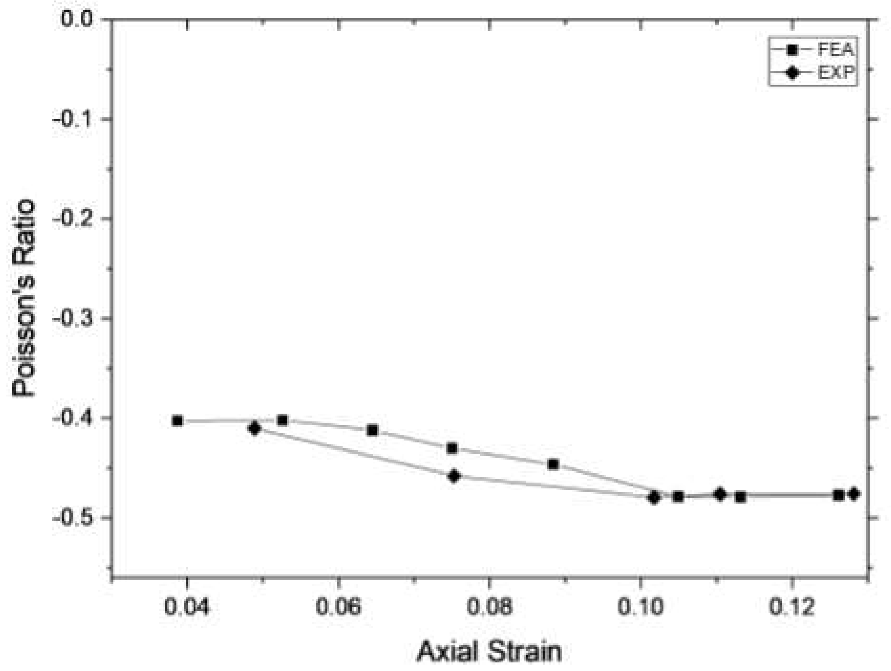
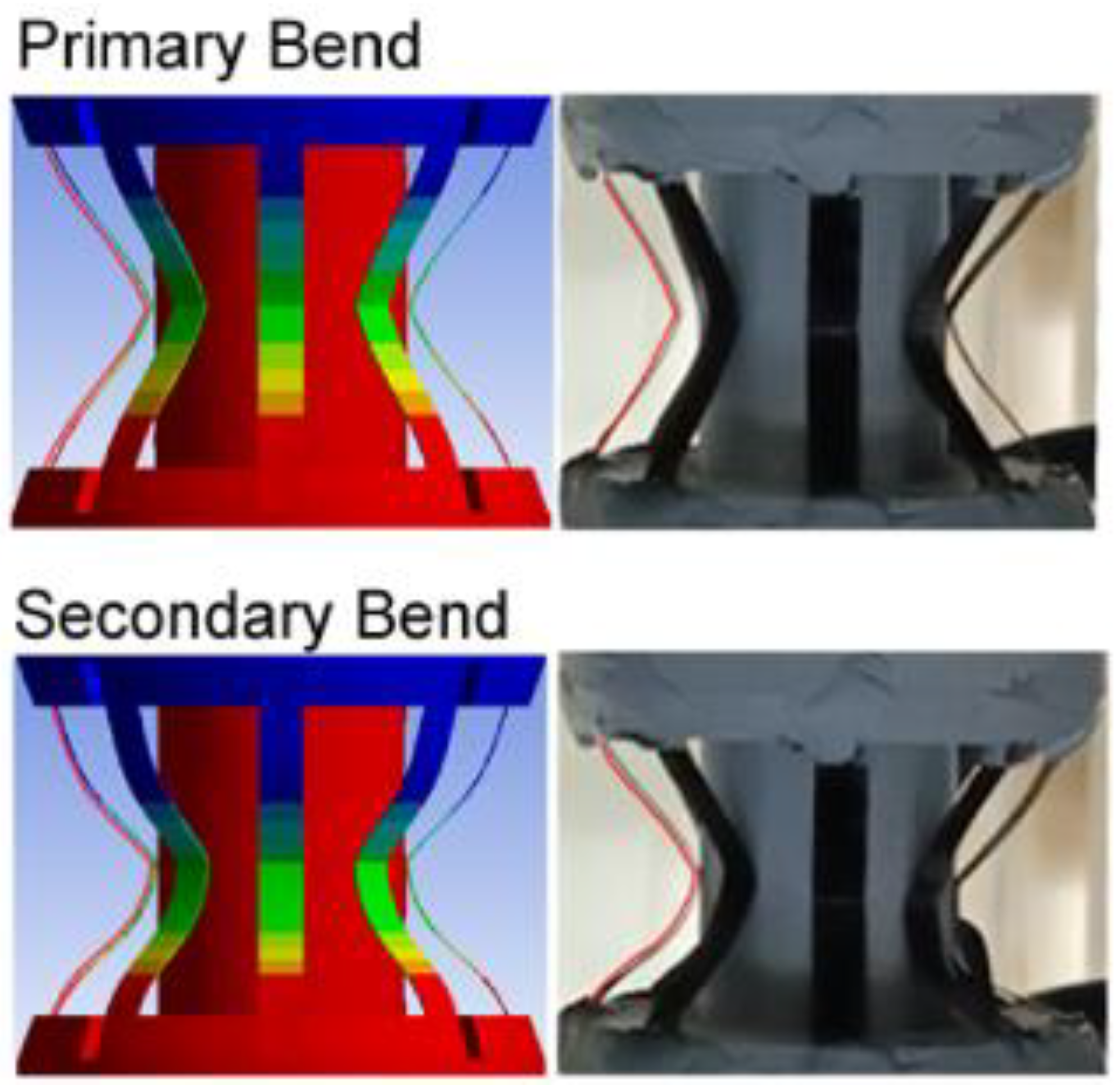
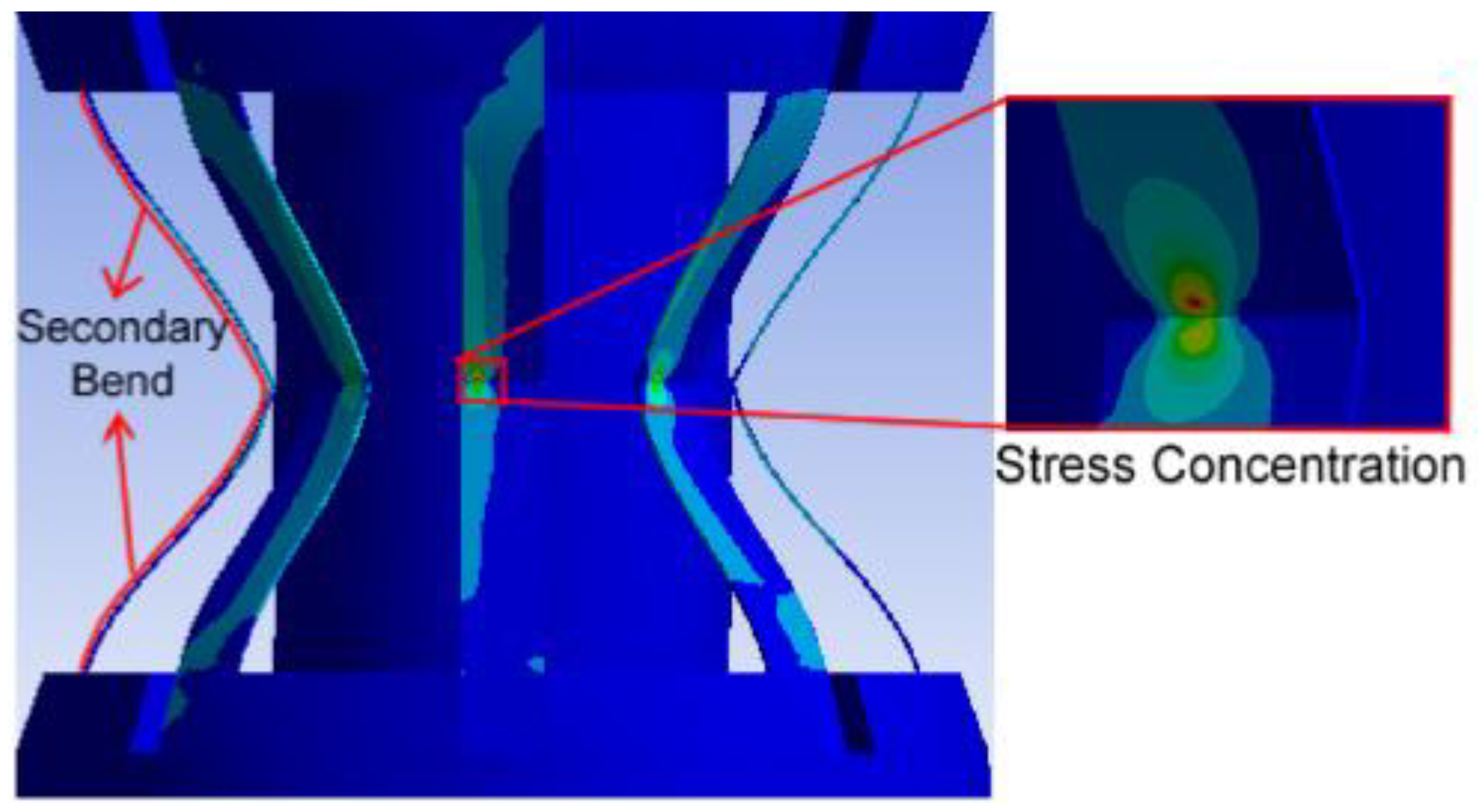
As shown in Figure 10, experimental and FEA results are in good agreement based on the trend of the curve and error is evaluated by 6.96%. By recording the experimental testing, a DIC (digital image correlation) is conducted to track the axial and transversal deformation during testing for comparison with the result of FEA (compared in Figure 10). Axial and transversal deformation could then be used to calculate the Poisson’s ratio of the system using equations in Section 2. The result is shown and compared with simulation result in Figure 11. Based on this, a matching deformation behavior between experimental and simulation results could be seen as Figure 12. The deformation behavior could be divided into two conditions; the first is the primary bend in which the initial bend of the ligaments is observed as a narrower angle than initial angle. This deformation would continue until the ligament makes the contact with the surface of lower shaft, in which the deformation at initial bend would stop, and initiating another bend denoted as a secondary bend.

3.2. Body weight case

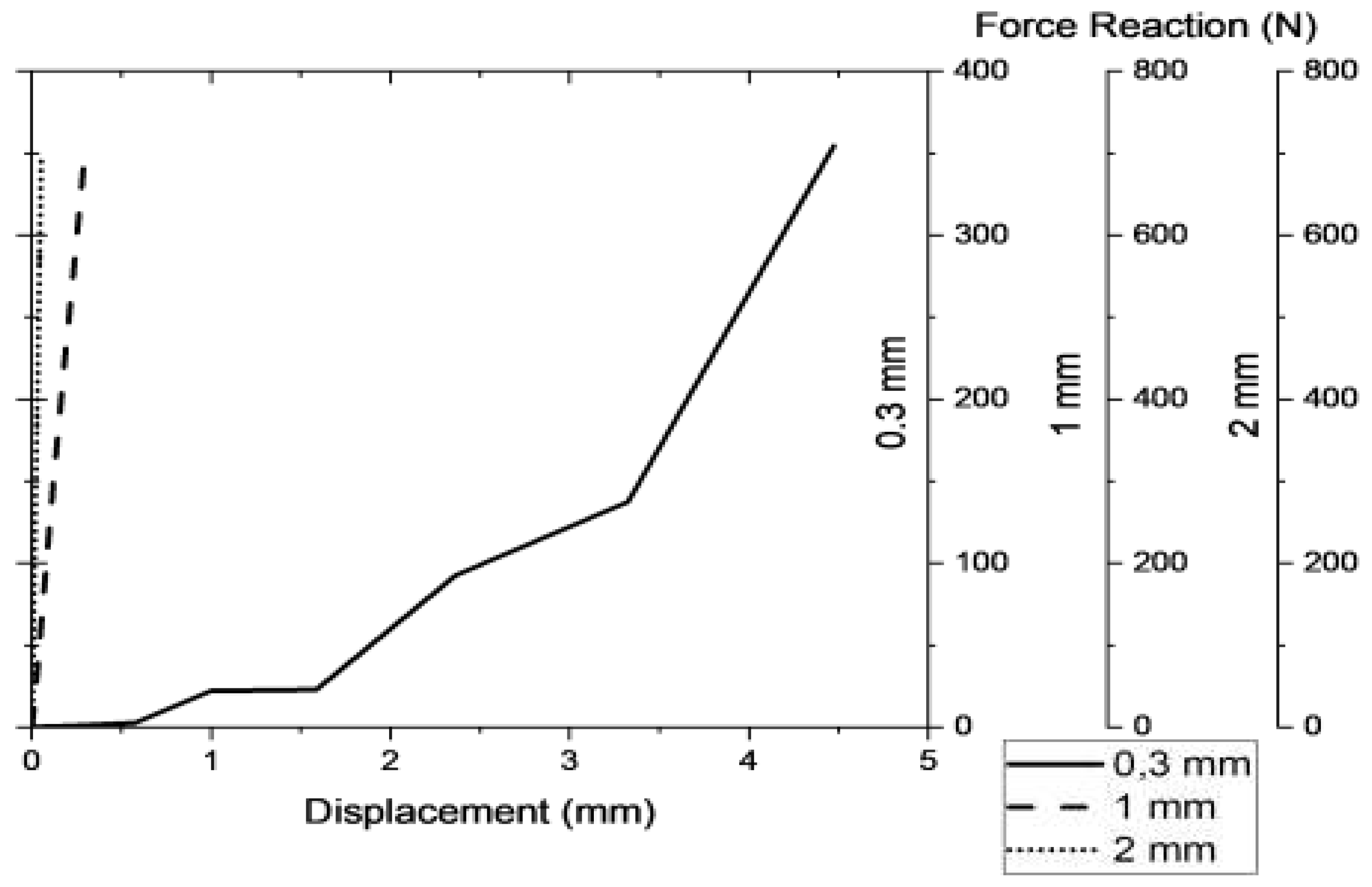
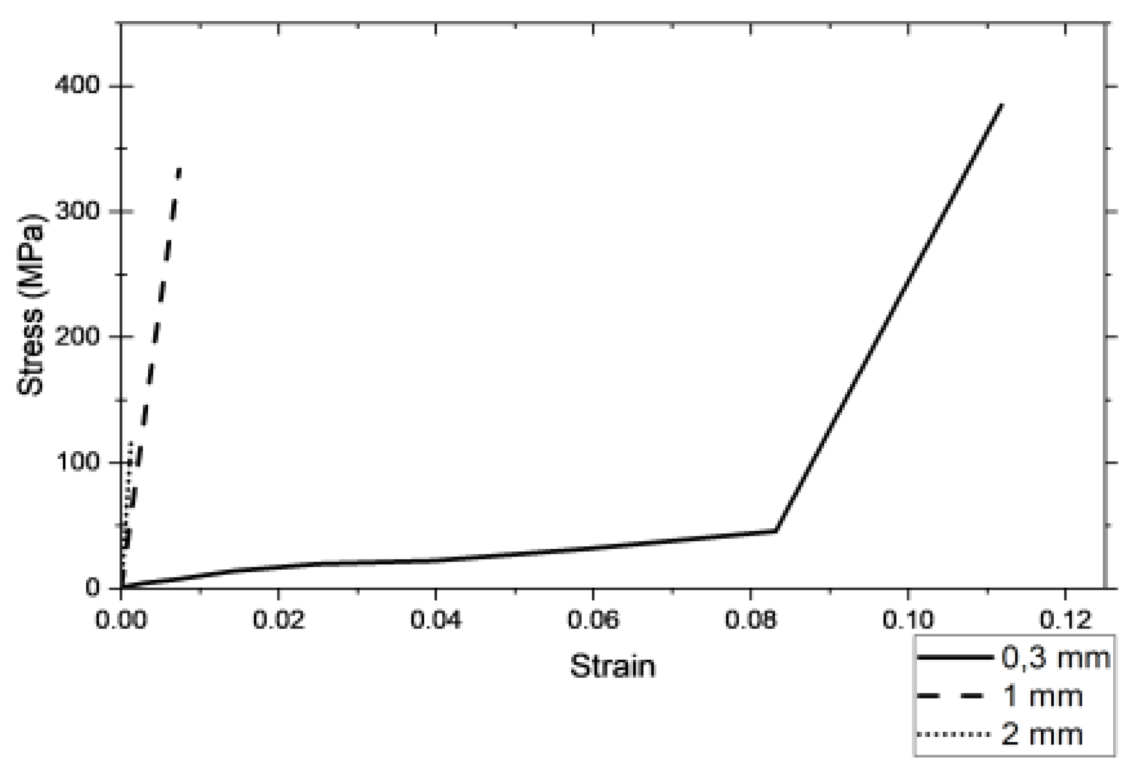
A finite element analysis simulating the condition of quasi-static load bearing has been conducted with varying ligament thickness. The results are recorded and both the force-displacement and stress- strain behavior are shown in Figure 13 and Figure 14, respectively. Based on Figure 13, the pylon with thickness of 0.3 mm shows the most displacement at 4.47 mm and lowest force reaction at 354.45 N. This shows that the 0.3 mm thickness could reduce the ground reaction force (51.6% reduction) compared to load input (686.6 N) by deforming. On the other hand, the thickness of 1 mm and 2 mm shows a very limited amount of deformation accompanied with no reduction to the ground reaction force compared to input load. Based on Figure 14, the ligament thickness of 0.3 mm also shows the highest stress compared to the other thickness variation. This was caused by the difference of cross-sectional area (refer to Eq. 4) where lower cross-sectional area with constant load would yield higher stress. A fluctuation of stress also occurs for 0.3 mm thickness due to the stress concentration caused by collision with lower shaft along with secondary bending deformation, illustrated in Figure 15.
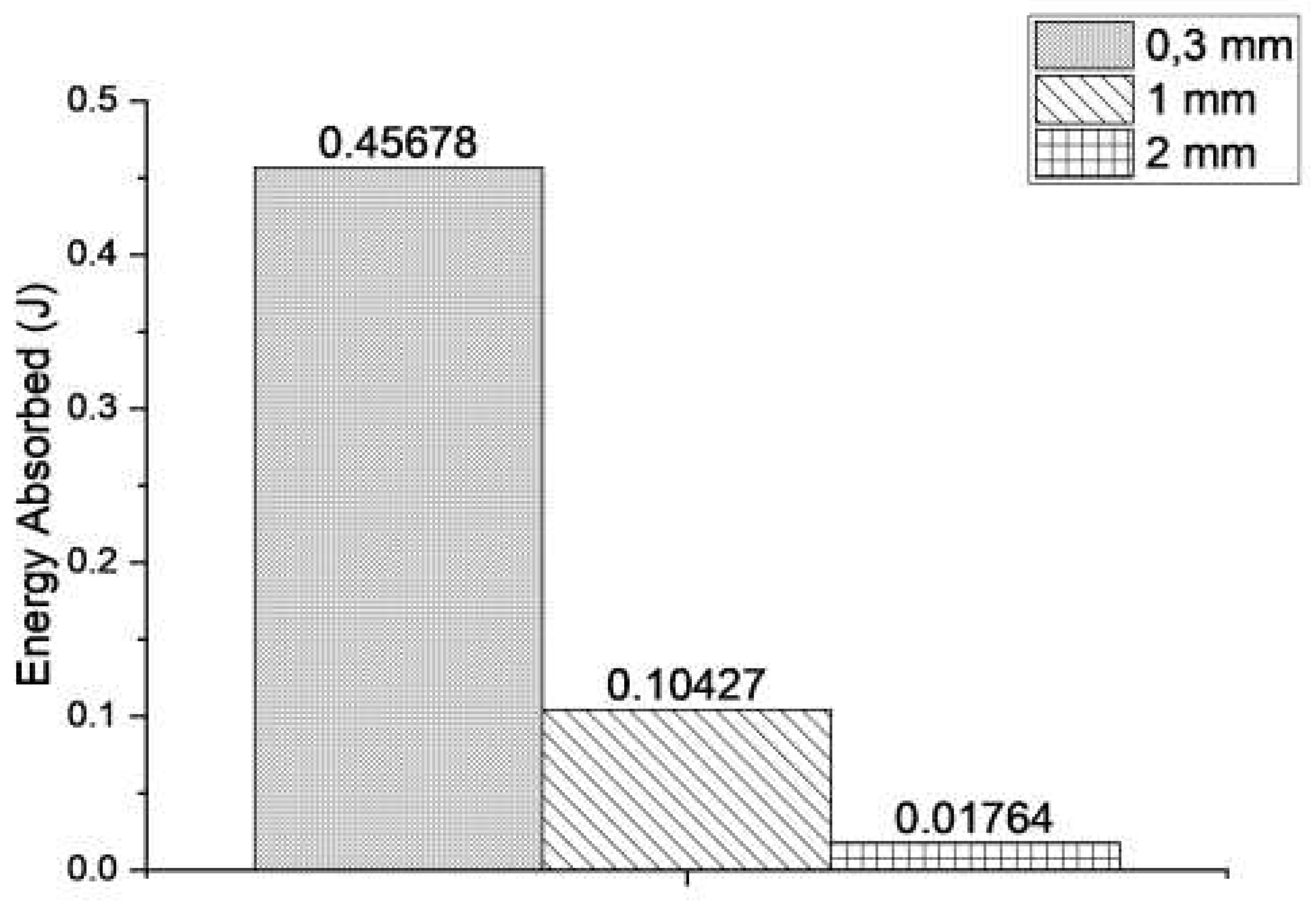
Based on the force-displacement curve, the energy absorption capacity of each variation could be calculated as the area under the curve or mathematically written based on force integral method where F defines the force over the deformation (S) as
Energy   Absorbed = F   d S
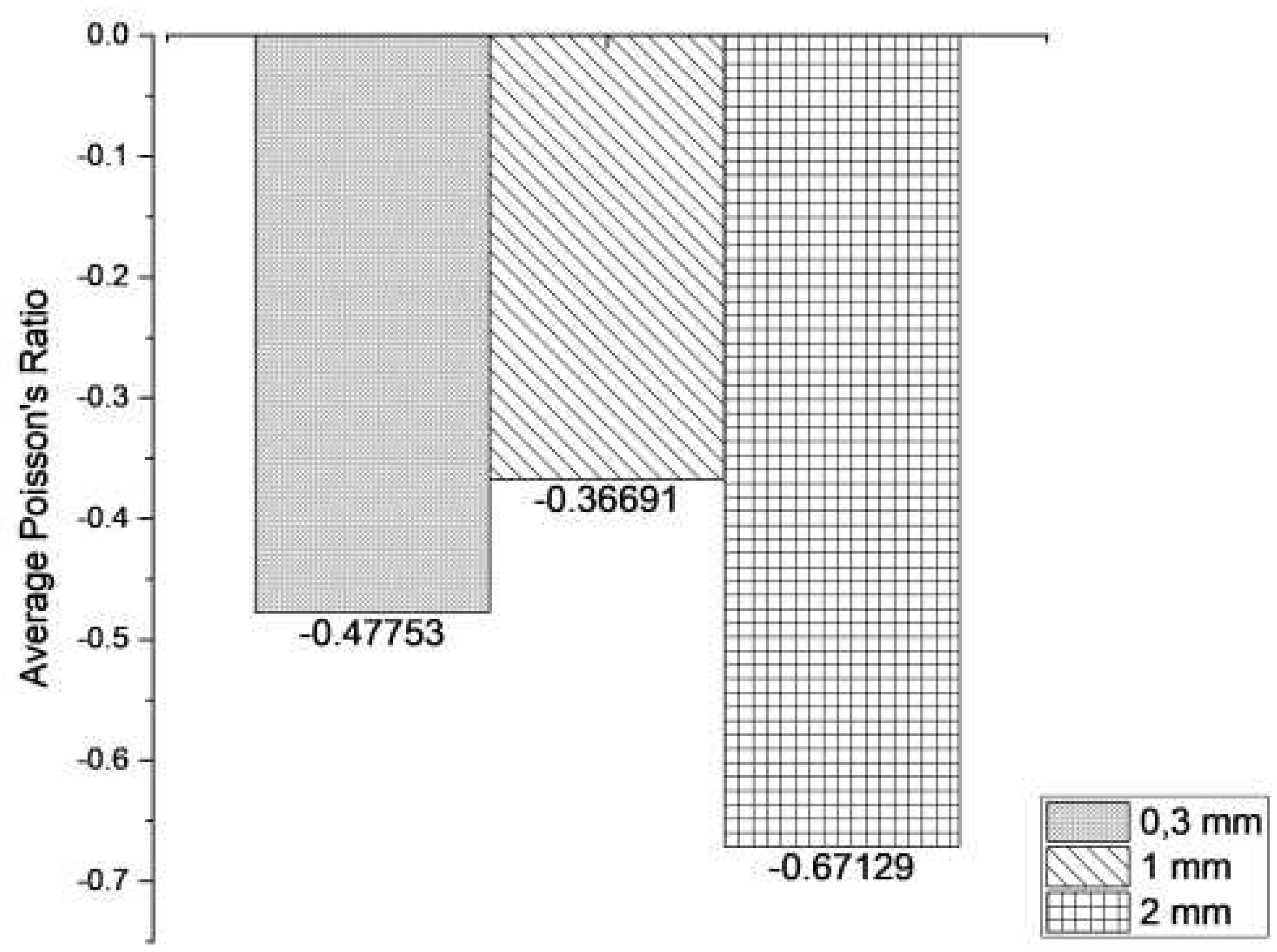
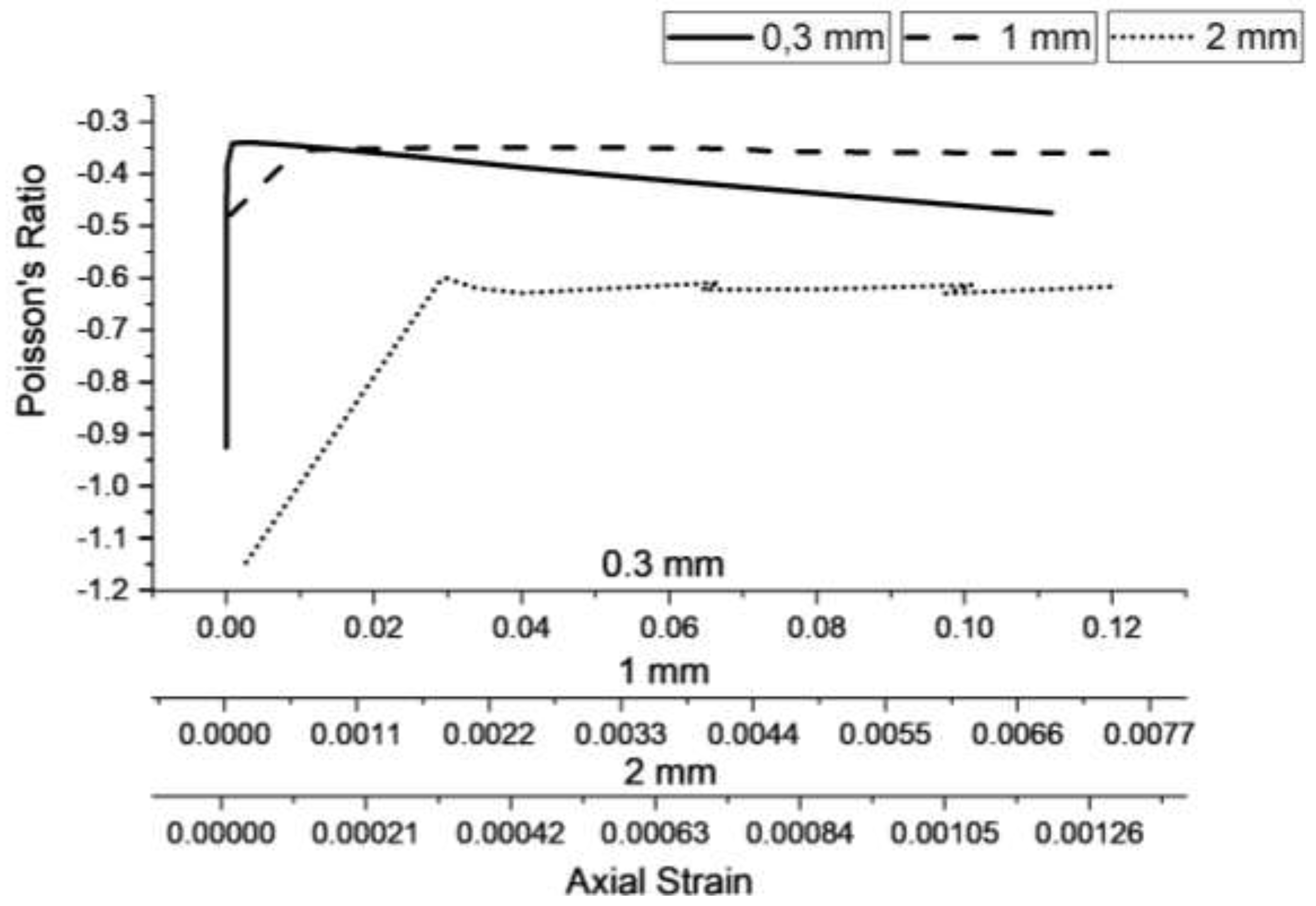
The energy absorption happening during simulation could then be calculated and compared for each thickness variations as shown in Figure 16. The ligament of 0.3 mm of thickness shows the highest energy absorption compared to the other thickness variations. This is aligned with the hypothesis that the pylon would be able to absorb energy by deforming. The structure would absorb more energy the more it deforms [22]. In terms of its Poisson’s ratio, it has been found that all thickness variation demonstrates negative Poisson’s ratio as expected of an auxetic structure as shown in Figure 17. This also confirms that the negative Poisson’s ratio of the original 2D model would remain, even if the design had been rearranged into 3D model in radial pattern. From Figure 17 it could also be seen that the ligament thickness of 2 mm experiences the highest average negative Poisson’s ratio. To further analyze the actual Poisson’s ratio of each variation, a comparison of Poisson’s ratio over its axial strain is carried out and shown in Figure 18. As shown in Figure 18, although the 2 mm thickness experiences the highest average Poisson’s ratio it is actually caused from the minimum axial strain happening. It could be seen from the trend that the Poisson’s ratio would raise as its axial strain increases. Thus, it could be argued that with equal deformation for each thickness variation, the Poisson’s ratio value would not differ significantly. Table 4 provides the stiffness coefficient for the pylon system and individual ligament achieved from the equations given in Section 2.

3.3. Gait simulation case

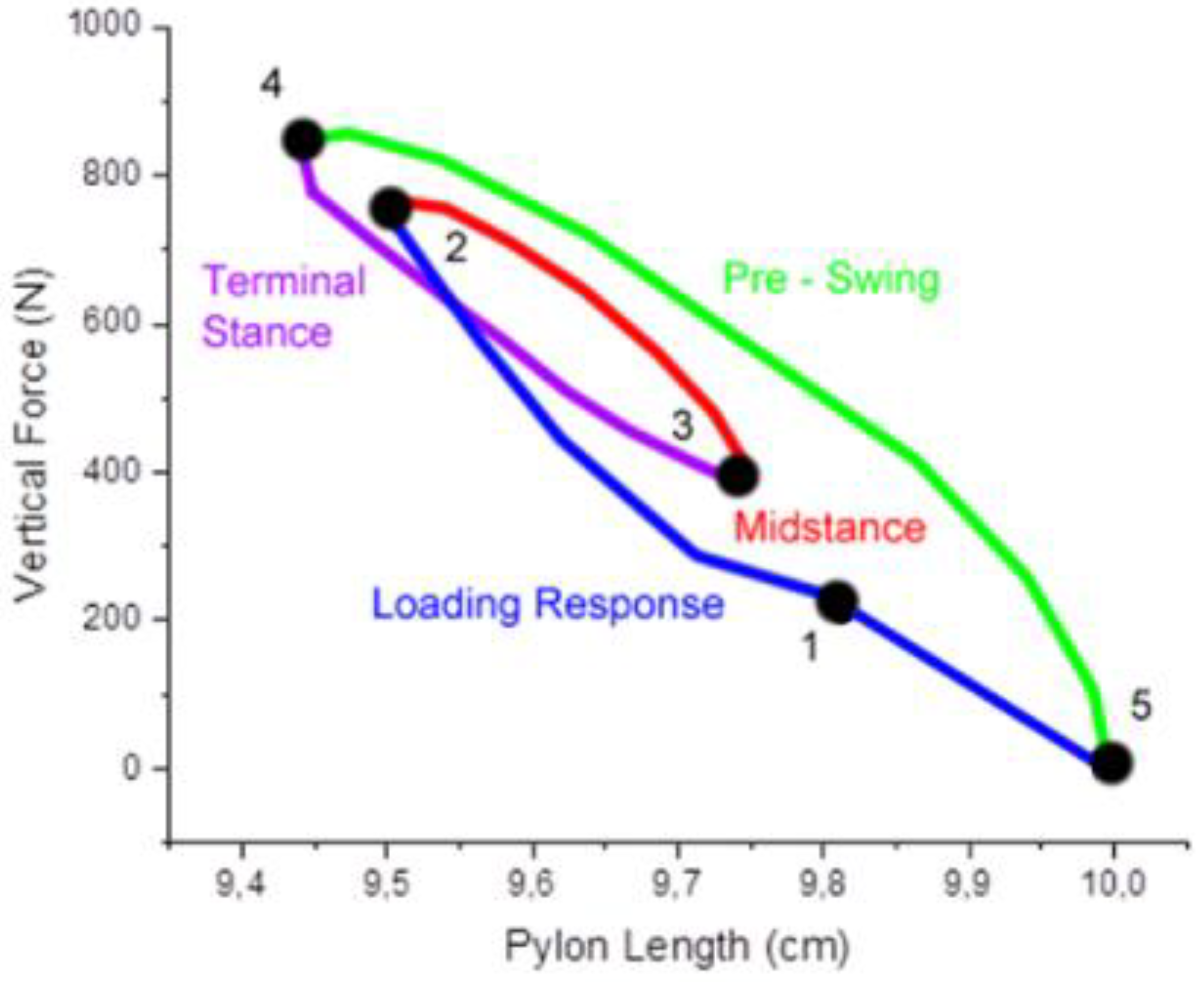
A gait simulation was conducted to analyze the behavior of the proposed pylon under gait conditions. For comparison, a similar study was conducted experimentally to define the effect of different stiffness on the behavior of shock-absorbing pylon (SAP) [23]. The stiffness for the proposed pylon (Table 4) could then be compared with commercially available SAP. Auxetic pylon with a thickness of 0.3 mm has the system stiffness coefficient closest to the soft SAP specification. Meanwhile, the auxetic pylon with 1 mm of ligament thickness shows a significantly stiffer behavior even when compared with the normal and medium stiffness of the SAP. Meanwhile, the auxetic pylon with 2 mm ligament thickness shows even more difference than normal SAP (at 8 times higher stiffness). The results of the gait simulation are shown in Figure 19. As expected, based on the stiffness coefficient comparison, the auxetic pylon with 0.3 mm of ligament thickness deformed the most, like the large deformation experienced by soft SAP. The variation of the vertical force depending on the pylon length is well identified in Figure 19. More specifically, the gait cycle starts with loading response, indicated by initial contact or heel strike (1), and this stage would continue until the weight are fully loaded on the leg (2). By the end of loading response, the pylon length has been reduced to 9.5 cm from its original length of 10 cm. On the next stage, as the weight gets distributed more evenly, the pylon length retracted gradually as the force reaction reduced until it would start the terminal stance (3). During terminal stance the length of pylon would reach its lowest at 9.43 cm during heel off (4) and then gradually decrease as the leg commence its swing phase until all the weight are released as the leg no longer in contact with the ground (5) and the length of pylon return to its original length of 10 cm.

4. Conclusions

In this work, a new design process for a pylon which can accommodate auxetic metamaterial structure for a transtibial prosthetics was carried out and its performance was evaluated through both simulation and experiment. The design procedures consist of three parts: the upper part as a function for the connection with socket, the middle part focusing on the main load bearing for connecting parts, and lower part representing the connector to the foot part. The auxetic metamaterial design was initially undertaken based on 2D re-entrant hexagon model and rapidly rearranged into 3D model to form eight ligament-like structure inserted between the upper and lower parts. The performances of the designed pylon were evaluated at two different conditions considering principal parameters of the body weight and gait motion. The effectiveness of the proposed design methodology for the prosthetic utilizing auxetic materials was validated through experimental testing of the prototype pylon. It has been shown that the pylon with the ligament thickness of 0.3 mm demonstrated the highest energy absorption due to the high reduction of the ground reaction force. This directly indicates that the pylon would absorb more energy with higher deformation. The deformation behavior demonstrated by the pylon could be denoted into primary and secondary bends. The primary bend was described as the deformation of the pylon in which the ligament initial bend angle can be deformed into the narrower angle. Subsequently, the ligament contacts with the lower shaft causes another secondary bend. This confirmed the viability of applying auxetic metamaterial structure which exhibits the negative Poisson’s ratio in 3D model transformed from 2D re-entrant hexagon. Consequently, the proposed design methodology of the transtibial prosthetics utilizing the auxetic metamaterials is simple and effective. This concludes that several different rehabilitation devices or systems such as prosthetics can be designed and manufactured using the proposed approach without significant modification.

Author Contributions

Conceptualization, U.U. and S.-B.C.; methodology, U.U. and B.W.L.; validation, U.U. and S.-B.C.; investigation, M.F.F. and B.W.L.; resources, M.F.F. and B.W.L.; data curation, U.U. and S.-B.C.; writing—original draft preparation, M.F.F. and B.W.L.; writing—review and editing, U.U., S.-B.C., and A.A.J.; visualization, M.F.F. and B.W.L.; supervision, U.U. and S.-B.C. All authors have read and agreed to the published version of the manuscript.

Data Availability Statement

The data used to support the findings of this study are included within the article.

Acknowledgments

The authors would like to thank the Universitas Sebelas Maret for financial support through Hibah Non APBN UNS 2024.

Conflicts of Interest

The authors declare no conflict of interest.

References

  1. Cipriani, C.; Controzzi, M.; Carrozza, M.C. Progress towards the Development of the SmartHand Transradial Prosthesis. 2009 IEEE International Conference on Rehabilitation Robotics 2009. [CrossRef]
  2. Herr, H.M.; Grabowski, A.M. Bionic Ankle–Foot Prosthesis Normalizes Walking Gait for Persons with Leg Amputation. Proceedings of the Royal Society B: Biological Sciences 2011, 279, 457–464. [CrossRef]
  3. Aziz, S.A.A.; Ubaidillah; Mazlan, S.A.; Ismail, N.I.N.; Choi, S.-B. Implementation of Functionalized Multiwall Carbon Nanotubes on Magnetorheological Elastomer. Journal of Materials Science 2018, 53, 10122–10134. [CrossRef]
  4. Pokaad, A.Z.B.; Hudha, K.; Nasir, M.Z.B.M.; Ubaidillah, N.A. Simulation and Experimental Studies on the Behaviour of a Magnetorheological Damper under Impact Loading. International Journal of Structural Engineering 2011, 2, 164. [CrossRef]
  5. Imaduddin, F.; Mazlan, S.A.; Ubaidillah; Zamzuri, H.; Fatah, A.Y.A. Testing and Parametric Modeling of Magnetorheological Valve with Meandering Flow Path. Nonlinear Dynamics 2016, 85, 287–302. [CrossRef]
  6. Wirawan, J.W., Ubaidillah, U., Lenggana, B.W., Purnomo, E.D., Widyarso, W. and Mazlan, S.A., 2019. Design and performance analysis of magnetorheological valve for upside-down damper. Journal of Advanced Research in Fluid Mechanics and Thermal Sciences, 63(2), pp.164-173.Maun, J.A.; Gard, S.A.; Major, M.J.; Takahashi, K.Z. Reducing Stiffness of Shock-Absorbing Pylon Amplifies Prosthesis Energy Loss and Redistributes Joint Mechanical Work during Walking. Journal of NeuroEngineering and Rehabilitation 2021, 18. [CrossRef]
  7. Rakbangboon, T.; Guerra, G.; Kla-arsa, S.; Padungjaroen, U.; Tangpornprasert, P.; Virulsri, C.; Sasaki, K. High-Level Mobility of Trans-Tibial Prosthesis Users Wearing Commercial and sPace Energy-Storing Prosthetic Feet. International Journal of Environmental Research and Public Health 2022, 19, 12606. [CrossRef]
  8. Radcliffe, C.W. Four-Bar Linkage Prosthetic Knee Mechanisms. Prosthetics & Orthotics International 1994, 18, 159–173. [CrossRef]
  9. Houdijk, H.; Wezenberg, D.; Hak, L.; Cutti, A.G. Energy Storing and Return Prosthetic Feet Improve Step Length Symmetry While Preserving Margins of Stability in Persons with Transtibial Amputation. Journal of NeuroEngineering and Rehabilitation 2018, 15. [CrossRef]
  10. Kowalczyk, M. & Jopek, H. Numerical analysis of the lower limb prosthesis subjected to various load conditions. Vibrations in Physical Systems 2020 31.
  11. Fardan, M.F.; Lenggana, B.W.; Ubaidillah, U.; Choi, S.-B.; Susilo, D.D.; Khan, S.Z. Revolutionizing Prosthetic Design with Auxetic Metamaterials and Structures: A Review of Mechanical Properties and Limitations. Micromachines 2023, 14, 1165. [CrossRef]
  12. Lees, C.; Vincent, J.F.V.; Hillerton, J.E. Poisson’s Ratio in Skin. Bio-Medical Materials and Engineering 1991, 1, 19–23. [CrossRef]
  13. Pendry, J.B. Negative Refraction Makes a Perfect Lens. Physical Review Letters 2000, 85, 3966–3969. [CrossRef]
  14. Pendry, J.B.; Holden, A.J.; Stewart, W.J.; Youngs, I. Extremely Low Frequency Plasmons in Metallic Mesostructures. Physical Review Letters 1996, 76, 4773–4776. [CrossRef]
  15. Narayana, S.; Sato, Y. Heat Flux Manipulation with Engineered Thermal Materials. Physical Review Letters 2012, 108. [CrossRef]
  16. Liu, Z.; Zhang, X.; Mao, Y.; Zhu, Y.Y.; Yang, Z.; Chan, C.T.; Sheng, P. Locally Resonant Sonic Materials. Science 2000, 289, 1734–1736. [CrossRef]
  17. Beer, F. P., Johnston, R., Dewolf, J. & Mazurek, D. Mechanics of Materials, McGraw-Hill. New York 2013.
  18. Lakes, R. Foam Structures with a Negative Poisson’s Ratio. Science 1987 235, 1038–1040.
  19. Qi, C.; Remennikov, A.; Pei, L.-Z.; Yang, S.; Yu, Z.-H.; Ngo, T.D. Impact and Close-in Blast Response of Auxetic Honeycomb-Cored Sandwich Panels: Experimental Tests and Numerical Simulations. Composite Structures 2017, 180, 161–178. [CrossRef]
  20. Mark, A.G.; Palagi, S.; Qiu, T.; Fischer, P. Auxetic Metamaterial Simplifies Soft Robot Design. 2016 IEEE International Conference on Robotics and Automation (ICRA) 2016. [CrossRef]
  21. Kim, H.-S.; Um, H.-J.; Hong, W.; Kim, H.-S.; Hur, P. Structural Design for Energy Absorption during Heel Strike Using the Auxetic Structure in the Heel Part of the Prosthetic Foot. 2021 18th International Conference on Ubiquitous Robots (UR) 2021. [CrossRef]
  22. Yang, H.; Wang, B.; Ma, L. Mechanical Properties of 3D Double-U Auxetic Structures. International Journal of Solids and Structures 2019, 180–181, 13–29. [CrossRef]
  23. Li, X.; Wang, Q.; Yang, Z.; Lu, Z. Novel Auxetic Structures with Enhanced Mechanical Properties. Extreme Mechanics Letters 2019, 27, 59–65. [CrossRef]
  24. Bodaghi, M.; Serjouei, A.; Zolfagharian, A.; Fotouhi, M.; Rahman, H.; Durand, D. Reversible Energy Absorbing Meta-Sandwiches by FDM 4D Printing. International Journal of Mechanical Sciences 2020, 173, 105451. [CrossRef]
  25. Yang, W.; Huang, R.; Liu, J.; Liu, J.; Huang, W. Ballistic Impact Responses and Failure Mechanism of Composite Double-Arrow Auxetic Structure. Thin-Walled Structures 2022, 174, 109087. [CrossRef]
  26. Um, H.-J.; Kim, H.-S.; Hong, W.; Kim, H.-S.; Hur, P. Design of 3D Printable Prosthetic Foot to Implement Nonlinear Stiffness Behavior of Human Toe Joint Based on Finite Element Analysis. Scientific Reports 2021, 11. [CrossRef]
  27. Mirzaali, M.J.; Janbaz, S.; Strano, M.; Vergani, L.; Zadpoor, A.A. Shape-Matching Soft Mechanical Metamaterials. Scientific Reports 2018, 8. [CrossRef]
  28. Zamani, M.H.; Heidari-Rarani, M.; Torabi, K. Optimal Design of a Novel Graded Auxetic Honeycomb Core for Sandwich Beams under Bending Using Digital Image Correlation (DIC). Composite Structures 2022, 286, 115310. [CrossRef]
  29. Yang, L.; Harrysson, O.; West, H.; Cormier, D. Mechanical Properties of 3D Re-Entrant Honeycomb Auxetic Structures Realized via Additive Manufacturing. International Journal of Solids and Structures 2015, 69–70, 475–490. [CrossRef]
  30. Reverte, J.M.; Caminero, M.Á.; Chacón, J.M.; García-Plaza, E.; Núñez, P.J.; Becar, J.P. Mechanical and Geometric Performance of PLA-Based Polymer Composites Processed by the Fused Filament Fabrication Additive Manufacturing Technique. Materials 2020, 13, 1924. [CrossRef]
  31. Hazimi, H.; Ubaidillah, U.; Alnursyah, R.; Nursya’bani, H.; Lenggana, B.W.; Wibowo Improvement of Space Tube Frame for Formula Student Vehicle. Proceedings of the 6th International Conference and Exhibition on Sustainable Energy and Advanced Materials 2020, 735–744. [CrossRef]
  32. Gard, S.A.; Konz, R.J. The Effect of a Shock-Absorbing Pylon on the Gait of Persons with Unilateral Transtibial Amputation. The Journal of Rehabilitation Research and Development 2003, 40, 111. [CrossRef]
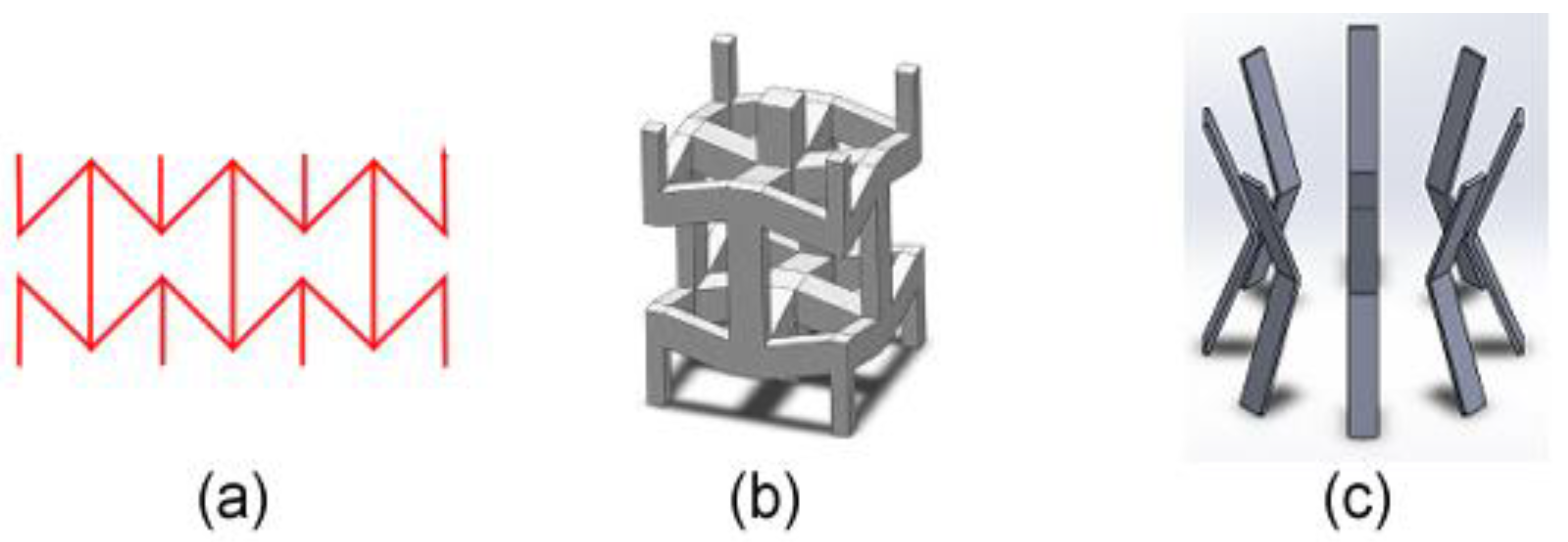
Figure 1. Examples of metamaterial-based devices; (a) design parameters for reoriented 3D reentrant hexagon structure, (b) design model for modified 3D reentrant structure [30], and (c) the proposed modified re-entrant hexagon arranged in 3D radial arrangement.
Preprints 98825 g001
Figure 2. Proposed auxetic pylon design placement; (a) a schematic of the transtibial prosthetic, (b) the geometries along with the indication for upper, middle, and lower components.
Preprints 98825 g002
Figure 3. Schematic configuration and geometry; (a) the proposed design configuration from the sides, (b) the simplified diagram illustrating the arrangement of the pylon and its ligaments, (c) the important parameters illustrated for calculating the stiffness coefficient.
Preprints 98825 g003
Figure 4. Schematic and photograph of ASTM E8 pin-loaded specimen.
Preprints 98825 g004
Figure 5. Results of ASTM E8 tensile testing in terms of force – displacement (left) and stress – strain (right).
Preprints 98825 g005
Figure 6. Photograph of sample prototype for the proposed pylon design.
Preprints 98825 g006
Figure 7. Mesh convergency analysis results tracking the maximum vertical displacement with varying mesh element size over the number of elements within the model.
Preprints 98825 g007
Figure 8. Simulation procedure (FEA analysis) from model generation, contact definition, meshing configuration, and boundary condition (from left to right).
Preprints 98825 g008
Figure 9. Body weight ratio over time during gait of a patient walking with the rate of 1.58 m/s.
Preprints 98825 g009
Figure 10. Comparison of FEA result and experimental result for validation.
Preprints 98825 g010
Figure 11. Comparison of FEA result and experimental result for validation in terms of Poisson’s ratio observed over axial strain during testing.
Preprints 98825 g011
Figure 12. Deformation comparison between experimental (right) and simulation results (left).
Preprints 98825 g012
Figure 13. Comparison of FEA result and experimental result for validation in terms of force reaction over axial displacement for 0.3, 1, and 2 mm of ligament thickness 3. Results.
Preprints 98825 g013
Figure 14. Comparison of FEA result and experimental result for validation in terms of stress over axial strain for 0.3, 1, and 2 mm of ligament thickness.
Preprints 98825 g014
Figure 15. The observed secondary bending mechanism found on the ligament and stress concentration during contact with the lower shaft.
Preprints 98825 g015
Figure 16. Energy absorption for each ligament thickness variations.
Preprints 98825 g016
Figure 17. Average Poisson’s ratio for each thickness variations.
Preprints 98825 g017
Figure 18. Poisson’s ratio over axial strain for each thickness variations.
Preprints 98825 g018
Figure 19. Force over pylon length during gait simulation for 0.3 and 1 mm of ligament thickness.
Preprints 98825 g019
Table 1. Mechanical properties of PLA [31].
Mechanical Properties Parameters
Density (g/cm3) 1.24
Young’s Modulus (MPa) 3420
Poisson’s ratio 0.3
Elongation at break (%) 4.2
Table 2. Mechanical properties of SK5 spring steel.
Mechanical Properties Parameters
Young’s modulus (GPa) 208
Yield strength (MPa) 1240
Table 3. Mesh convergency analysis for ligaments of the middle part.
Element Size Number of Elements Max. Displacement
1 5262 -4.407
0.9 5982 -4.4889
0.8 6910 -4.4977
0.7 7966 -4.4789
0.6 9582 -4.4755
0.5 11742 -4.4827
0.4 17038 -4.474
0.3 27310 -4.472
Table 4. Stiffness coefficient for system and individual ligament of varying ligament thickness.
Ligament Thickness (mm) Stiffness Coefficient (kN/m)
System Individual Ligament
0.3 79.24 9.9
1 2,371.6 296.45
2 13,344 1,668
Disclaimer/Publisher’s Note: The statements, opinions and data contained in all publications are solely those of the individual author(s) and contributor(s) and not of MDPI and/or the editor(s). MDPI and/or the editor(s) disclaim responsibility for any injury to people or property resulting from any ideas, methods, instructions or products referred to in the content.
Copyright: This open access article is published under a Creative Commons CC BY 4.0 license, which permit the free download, distribution, and reuse, provided that the author and preprint are cited in any reuse.
Prerpints.org logo

Preprints.org is a free preprint server supported by MDPI in Basel, Switzerland.

Subscribe

© 2024 MDPI (Basel, Switzerland) unless otherwise stated