Submitted:
05 January 2024
Posted:
15 January 2024
You are already at the latest version
Abstract
The swelling behavior of titanium-modified austenitic stainless steel 15-15Ti was investigated by pre-implantation of He at room temperature followed by Ni irradiation at 580 °C to peak doses of 120, 240 and 400 dpa. Relatively smaller cavities were observed in the zone of helium implantation while large cavities appeared in the region near the damage peak. A correction formula of the dpa curve was proposed and applied for samples with large swelling. It is found that the steady-state swelling rate of 15-15Ti keeps at ~1% /dpa even to high doses. By comparing the swelling data of the helium-implanted and helium-free regions at same doses, 70 dpa and 122 dpa, the suppression of excessive helium on swelling can be deduced at such doses.
Keywords:
15-15Ti
; ion irradiation
; irradiation swelling
; helium effect
; steady-state swelling
1. Introduction
Austenitic steels are selected as fast reactor fuel cladding materials because of their excellent high-temperature strength and fine machinability [1,2]. To boost long-term economic performance for the Sodium-cooled Fast Reactor (SFR), the dose of fuel assembly could reach up to 200 dpa in the future [3]. In the Generation IV SFR program, the integrity of fuel pins is highly dependent on whether the cladding can withstand the high temperature and high burnup irradiation. Swelling remains one of the defining challenges to the structural integrality of claddings in service [4]. Type 316 stainless steel (SS) was chosen as the cladding material for protype fast reactors, but it showed excessive swelling at doses above 50 dpa. It was shown that by adding stabilizing elements, adjusting chemical composition and introducing cold work, swelling can be reduced significantly. The titanium-stabilized austenitic stainless steel 15-15Ti derived from 316 SS exhibits enhanced swelling resistance as a result of increased nickel content and the formation of intragranular nano-sized TiC precipitates [4,5]. Between 1982 and 1998, 15-15Ti cladding was used in the Phénix reactor, and the maximum damage dose reached 130dpa. It was reported that the deformation of 15-15Ti is still acceptable. Similar alloys have been selected as core materials for faster reactors, such as ChS-68 (Russia), D9 (USA), D9I (India), Din 1.4907 (Germany) and JPCA (Japan) [6,7].
The swelling of austenitic steels as a function of damage dose is usually characterized by an incubation period in which the swelling is very small or negligible at lower doses, a transient regime and finally the steady-state of swelling. The nucleation of cavities mainly occurred during the incubation period, resulting in an increase of the number density but no significant change in size [2]. The size of cavities continually increases with accumulating dose, as the generation and absorption rate of vacancies exceed the emission rate. In the stage of steady-state swelling, the swelling rate is nearly independent of dose rate, temperature, and alloying chemistry for a given material. The theoretical analysis suggested that when dislocations and cavities produced by irradiation were of comparable sink strengths, the separation between interstitials and vacancies was most effective, resulting in the steady-state swelling with the maximum swelling rate [8]. Steady-state swelling rate can be used to describe the irradiation resistance of a material [2]. Typical steady-state swelling rate is ~1% /dpa and ~0.2% /dpa for austenitic and ferritic / martensitic steels, respectively [9]. In bcc steels, the lower dislocation bias for preferential absorption of interstitials results in a lower rate of steady-state swelling [10].
In-pile irradiation and post irradiation examination of materials are costly and generally time-consuming. The induced radioactivity also makes it inconvenient for post irradiation examinations. Heavy-ion irradiation can yield high damage rates without residual radioactivity and at very low cost [11]. Therefore, heavy-ion irradiation is widely used as a surrogate method for neutron irradiation [11,12,13,14,15,16]. Ion irradiations have been critical not only in the research and understanding of radiation effects, but also in the development of innovational materials used in reactors. A great deal of research has been devoted to the understanding of the mechanisms of irradiation-induced swelling using ion irradiation. For example in Ref. [15], it was demonstrated that the steady-state swelling rate (~1% /dpa) of annealed AISI 304L SS could be reproduced using self-ion irradiation up to ~60 dpa. The swelling rates of two austenitic alloys, cold-worked 316 steel and alloy A709, both reach ~1% /dpa eventually between 200 and 300 dpa using Fe irradiation [16]. However, the evolution of swelling for more irradiation-resistant materials, such as the 15-15Ti steel, is limited at very high doses.
For ion-irradiated materials, extra interstitials introduced by ion implantation will suppress swelling by reducing the cavity nucleation rate when defect recombination is an important process [17]. Such process would have far-reaching consequences in the more swelling-resistant steels. It was shown in Ref. [18] that much less cavities were produced in the solution-annealed JPCA irradiated to 50 dpa at 750 and 800 K by heavy ions, comparing with the 316 SS. Cavity denuded region can be observed near region of damage peak [19]. In order to compensate for the swelling suppression of extra interstitials, the implantation of insoluble helium before the heavy-ion irradiation was frequently used to enhance the cavity nucleation [20,21,22,23]. However, the role of helium, particularly its concentration, is complicated in the evolution of swelling [24,25,26,27,28,29,30,31,32,33,34]. The effect of helium on swelling is believed depends on not only the dose but also the helium concentration [29]. It was shown both in cold-worked and solution annealed austenitic steels that the cavity density tends to increase markedly and the cavity size decreases gradually with increasing He/dpa ratio [20,29]. The cavity density tends to approach a saturation while the mean cavity size continues to decrease when the helium concentration exceeds an intermediate He/dpa ratio. In the framework of dislocation bias model, the swelling is driven by the biased absorption of interstitials and vacancies [27]. The preferential absorption of interstitials by dislocations results in a vacancy super-saturation in the matrix. At the same time, the helium-induced cavity nucleation increases swelling. As the helium concentration continues to increase, the increasing number of cavities which are the neutral sinks promotes the recombination of interstitials and vacancies. Therefore, the swelling is hindered.
In this paper, the swelling behavior of 15-15Ti austenitic steels under ion irradiation was investigated to very high doses. By pre-implanting helium, the irradiation damage region bombarded by heavy-ions can be splitted into the helium-implanted and the helium-free regions. The cavity morphology and swelling of both regions was examined by the transmission electron microscopy (TEM). The synergistic effect of helium with the displacement damage on swelling was discussed.
2. Experimental procedure
2.1. Materials and Irradiation experiment
The base material used in this paper is a 20% cold-worked 15-15Ti steel. The nominal composition of this steel was given in Ref. [23]. The 15-15Ti steel in the form of cladding tube was sectioned into Φ15 mm×1.5 mm disks by electrical discharge machining. The specimens were then mechanically ground and fine-polished to a mirror-like surface prior to irradiation [23].
The irradiation experiments were carried out at the triple beam irradiation facility in China Institute of Atomic Energy (CIAE) [35]. The facility consists of an HI-13 tandem accelerator, a 300 kV helium implanter and a 300 kV hydrogen implanter. In the irradiation chamber, the sample were mounted on a copper base and connected with a PNC/PC heater. The sample can be heated from room temperature to 800 ℃. A hole is drilled in the middle of the copper base and brazed with a K-type thermocouple to monitor the temperature. A thermostat was connected to the heater and the thermocouple so that the target temperature can be adjusted automatically to a preset value with an accuracy of ± 2 ℃.
The specimens were pre-implanted with helium at room temperature before the heavy ion irradiation in order to promote cavity nucleation at low doses. A plateau of helium concentration in the depth zone of 350 to 700 nm under the irradiated surface was created by multiple energy implantation. In a rate theory calculation, the swelling of 15-15Ti will increase with increasing helium concentration and will reach a saturation at high appm of helium [36]. The maximum helium concentration was set to be 13, 000 appm on the plateau. The profile of implanted helium is shown in Figure 1(a). Previously it was observed by TEM that there is no helium bubble or void for the similar specimen implanted with helium at room temperature [23].
The specimens pre-implanted with helium were irradiated using 75 MeV defocused Ni beam through a Ta foil of ~ 4 μm thickness. The defocused beam was preferred compared with the raster scanning beam as discussed in the ASTM E521 standard [36,37]. The tantalum foil was fixed in front of the sample to reduce the beam energy and to further defocus the beam.
Swelling only occurs in a certain range of temperature. If the irradiation temperature is lower, the defects are less mobile and less likely to form larger clusters. At higher temperatures, vacancies can emit from the cavities, which counterbalances the net vacancy flow towards the cavities, limiting growth [27,39]. The maximum swelling occurs at an intermediate temperature, known as the temperature of peak swelling. This temperature is not only dependent on the material but also the dose rate [27,40,41] and hydrogen/helium concentrations in multiple-beam irradiations [30]. It will shift to higher temperature with the increasing dose rate. The temperature of swelling peak in the heavy-ion irradiation of austenitic steels has been measured with various characterization methods, such as the positron annihilation techniques [35] and the TEM examinations [30]. These studies suggest that this temperature is around 580 ℃~590℃[40] in heavy-ion irradiations generally with a dose rate in the range of 10−2~10−3 dpa/s. In this paper, heavy-ion irradiation was performed at 580 ℃, the temperature of peak swelling, to the peak doses of 120, 240 and 400 dpa. Correspondingly, the doses in the helium implantation zone reached 30, 60 and 122 dpa, respectively. The damage was calculated by the SRIM [42] code using using the Kinchin-Pease model, as shown in Figure 1(b). The displacement energies of Fe,Cr and Ni were set to be 40 eV [43].
2.2. Swelling measurement
After the irradiation, TEM lamellas were fabricated by the standard life-out technique using a TESCAN Lyra3 focused ion beam (FIB). TEM observations were carried out by a JEM-2100F microscope. The smaller cavities were observed under the kinematical diffraction condition using the bright field imaging. They were measured in diameter and counted in the selected region.
In this paper, Electron energy-loss spectroscopy (EELS) was employed to measure the local thickness of TEM samples. EELS involves measurement of the energy distribution of electrons that have interacted with a specimen and lost energy due to inelastic scattering. It allows a quick and reliable measurement of local thickness in transmission electron microscopy. Local thickness can be calculated by , where t is the sample thickness, the mean free path of electrons, and the integrated intensity of the total and zero energy loss peak, respectively. The λ values were measured to be 102, 104 and 98 nm for 200 keV electrons in Fe, Cr and Ni, respectively [44]. Then the λ value for 15-15Ti can be obtained by weighting its main compositions, which gives 102 nm.A typical TEM image and the selected area where EELS was taken are shown in Figure 2(a) and (b). The average thickness of the TEM lamella can be calculated at the same area as the cavity swelling measurement, as indicated in Figure 2(c).
The swelling caused by smaller cavities compared with the thickness of the TEM specimen can be calculated as follows,
where is the region of cavities, and V is the selected region of measurement. According to the procedure in Refs. [23,38], the cavity volume fraction is corrected due to intersection of cavities with the surface, which is calculated by
where A and t are the area and the average thickness in which measurements are made.
and are the diameter and observed number of cavities in size class i. For multiple regions, the total cavity volume fraction can be written as follows
where k indicates different region. A typical image ( the dose of helium Implantation zone is 30 dpa) with multiple TEM recordings is shown in Figure 3. The rectangle define the area where the voids are evaluated. The width of that area is larger than 150 nm. The swelling of a specimen is given by the maximum value calculated with a band width of 150 nm. The swelling is readily calculated using Equation (1).
However, the swelling calculated by the above method will be seriously overestimated if the diameter of cavities is in the similar size with or larger than the thickness of a TEM sample. For the cavities completely cutting through the TEM sample, the swelling can be calculated using , where is the region of cavities, and A is the selected region of measurement.
2.3. The correction of damage profile
The significant swelling induced by cavities will distort the distribution of displacement damage. The swelling is cumulated as cavities grow with time or dpa, therefore it seems that the dpa profile should be corrected spatially and temporally. However, the detailed evolution of swelling as a function of dpa is generally not known, thus it is impossible to take the time evolution of swelling in account accurately. To account for the effect of cavity swelling on the damage profile, various correction methods were developed usually using reduced mass density in the SRIM calculations, see Refs. [16,45].
The fixed damage rate method and the fixed depth method were proposed in Ref. [45]. In the fixed damage rate method, the dpa profile is simply stretched according to the swelling profile. In the fixed depth method, the dpa profile is corrected by using the reduced density in SRIM calculations. The mass density of each bin is calculated from the swelling profile at the final state, i.e. the worst case, or the averaged swelling profile at the beginning and the end of the irradiation. In any case, the dpa peak would be the same in both methods. Authors have preferred the fixed depth method because the inaccurate overlapping of dpa, injected interstitial and pre-implanted helium could lead to unfair comparison between different doses. Kim also proposed a correction procedure by using a reduced mass density which evolves with swelling in the SRIM calculations [16]. However, the density correction formula used in Ref. [16] and Ref. [45] is an approximation to the accurate one. A small difference of dpa peaks before and after the correction is more likely due to this approximation error at large swelling. It should be noted that not only the dpa profile but also the injected interstitial and helium profile should be corrected, as they will be pushed to the deeper region in the case of swelling.
In the following, we will re-derive the dpa correction formula using an accurate reduced density. The basic idea is that cavities do not cause any energy loss. The formalism is essentially the same as the fixed damage rate method, as shown Figure 4.
Assume the unirradiated materials before the depth h are divided into n bins. Considering a bin at depth of h before irradiation, because of the mass conservation, the mass density at the expanded depth h’ reads
where S (h’) is the local swelling at the expanded depth h’. In the case of small swelling, the above equation can be approximated as ρ’ (h’) = (1-S)ρ, exactly the same as the Equation (1) in Ref. [16]. However, it would be inaccurate for large swelling. Because there is no lateral expansion in the ion irradiation, the mass conservation can also be written as
By summing up all bins from surface to h’, we have
Assuming that the swelling is caused by cavities and there is no energy loss in them, the number of displaced atoms per injected ion remains the same in each bin whether there is swelling or not, the same is true for the dpa rate or total dpa, i.e.
where is the original dpa profile, and is the corrected dpa profile. Now it is free to make a change of h’→h, so we get a correction formula for dpa. As for the concentration of injected interstitial and helium in a bin, because they are calculated as the ratio of deposited atoms to material atoms in this bin, similar to that for displaced atoms, Equation (7) can also be used to correct the concentration profile for injected interstitial and helium.
Equation (8) seems problematic because the swelling is a changing factor during the irradiation. In the following, we will prove that there is no need to consider the time dependence. Assuming the unirradiated materials before the depth h are divided into n bins and the irradiation period is divided into m time intervals, Sij is the swelling for the ith bin during the jth time interval. The bin at depth h will be at h' after the irradiation. It can be expressed by the sequential increment of depths in each time interval,
where hj is the depth of the bin at original h after the jth time interval, and is the thickness of the ith bin after the jth time interval. It can be easily proved that Equation (8) can be rewritten as,
Alternatively, Equation (9) can be written in a differential form, i.e.
where S (h) is the swelling of the bin at original h . In practice, the swelling is measured at the final state of an irradiated sample. We should make a change of swelling as a function of depth, then we have
Equation (11) is actually the same as Equation (6). In other words, the dpa profile can be corrected by stretching the dpa profile using the depth dependent swelling data. This can be understood by a schematic drawing in Figure 4. Assuming that cavities are uniformly distributed and do not cause any energy loss, the damage rate is actually the same at h and h’, for the unirradiated and irradiated samples. It is also valid if reduced density for each layer is used in SRIM calculations.
3. Results and discussion
TEM images of irradiated samples with different dpa are shown in Figure 5, overlapped with the damage curves. Small cavities can be seen in the helium implanted zone around depth of 1 μm (Figure 5d–f), while large cavities were observed in the deeper regions, which are beyond the helium implantation ranges, see Figure 5a–c. Particularly for the sample with the peak dose of 400 dpa, the cavities coalesced to very large cavity near the damage peak [46]. No cavity was observed at the damage peak. It is noted that the size of cavities generally increases with increasing dose in both helium-implanted and helium-free regions. Swelling did not occur in the peak damage region, indicating that the injected Ni ions suppressed swelling at the damage peak during irradiation[47,48], in other words, the local vacancy supersaturation was lower than the threshold for cavity swelling.
Swelling was not observed in 15-15Ti by single beam irradiation with nickel even if the irradiation dose was over 100 dpa [49]. However large swelling was observed in the region of presumably helium-free. In Ref. [50], it was shown that the helium could diffuse further into deeper region due to the vacancies created by ion bombardment. Those helium could enhance the cavity nucleation which can lead to significant swelling when combined with large doses.
Based on the fact that cavities do not cause any energy loss of injected ions, a dpa correction formula is re-derived in section 2.3. The dpa profile is like stretching the original curve for an irradiated sample. In order to do the dpa profile correction, the TEM images were divided into 5 bins of equal width and the swelling of each bin was measured. The depth dependent swelling was then interpolated from the data of sectioned bins. Using Equation (7) in section 2.3, the damage curve was corrected and is shown in Figure 5b,c overlapped with the TEM image.
Compared with the helium-implanted zone and the region with large cavity, the size of cavities is smaller and the number density is larger in the helium-implanted zone than that in the displacement-damage-only region under the same dose. Note that the helium implantation zone in Figure 5b and the region just beyond the helium implantation range in Figure 5a receive a similar dose of 70 dpa. However, the cavities in the latter region are significantly larger than those in the helium zone, indicating that the implanted helium may play a role in the growth of cavities. The abnormality can be found comparing two regions in Figure 5c,b where the irradiation dose is around 122 dpa.
The cavities in the helium-implanted zones were measured and counted at different doses, with their size distribution shown in Figure 6. It is seen that the tail of the size distribution increases markedly with increasing dpa, although the peak shifts only moderately to the higher size, from ~ 5.5 nm to 7.5 nm as the damage increases from ~30 dpa to ~122 dpa. Much larger cavities over a hundred nanometers were seen in the helium implantation zone as the damage reaches ~122 dpa.
The cavity density in helium-implanted zones was compared in Figure 7. It is seen that the cavity density decreased significantly as the increasing dose. Previous study has shown that voids rather than bubbles predominate in specimens after helium implantation and followed by high dose heavy ion irradiation [23]. The increase in cavity size and the decrease in density are mainly due to the growth and coalescence of cavities with the increasing dose.
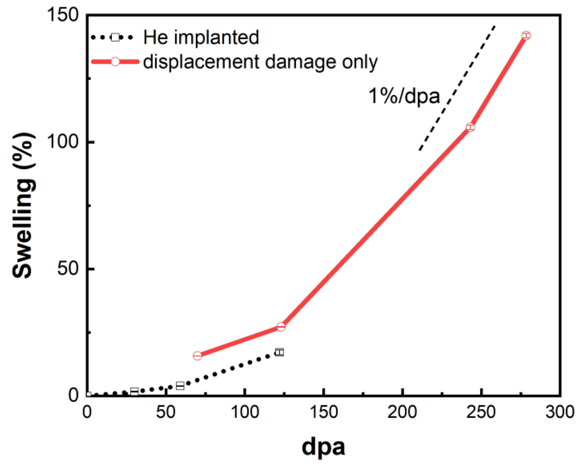
The cavity swelling in the helium-implanted zone and the helium-free region near the damage peak as a function of dpa were drawn in Figure 8. It can be seen that the swelling is more than 100% at 243 dpa and increases up to 142% at 278 dpa. As discussed in the previous paragraphs, the swelling increases with the increasing dose in these two regions. In the helium-free region, it is found that a steady-state swelling rate reaches ~1% /dpa at high doses. And it can be seen more clearly that the swelling in the helium-implanted zone is lower than that near the damage peak region in the range of 70 - 122 dpa. In the dislocation bias model, swelling is caused by bias-driven vacancy growth, which requires excess vacancy flux [51]. Cavities such as helium bubbles become the main point defect sinks due to the increase of density in the presence of excessive helium. Plentiful cavities as neutral sinks result in nearly equal absorption of interstitials and vacancies, thereby inhibiting cavity growth and suppressing swelling [27].
4. Conclusions
In summary, the swelling behavior of 15-15Ti stainless steel was investigated by pre-implantation of helium at room temperature followed by Ni ion irradiation at 580 ℃ to peak doses of 120, 240 and 400 dpa. TEM lamellas were prepared and observed for the irradiated samples. The electron energy loss spectroscopy was used to measure the thickness of the regions with cavities in the TEM lamellas. The swelling induced by smaller sized cavities was calculated based on the cavity and thickness measurement in the same region. Large cavities were observed in the region with displacement damage only and coexist with smaller cavities in the helium implanted zone. The swelling in the region of large cavities was determined by measuring the porous region. A correction formula of the dpa curve was proposed using more accurate reduced densities and based on the assumption that the cavities do not cause any energy loss.
The size of cavities increases but the density decreases with increasing dose in both helium-implanted and helium-free regions, which mainly attributed to the growth and coalescence of cavities under irradiation. The 15-15Ti shows severe swelling at high doses, with swelling exceeding 100% at 243 dpa. The steady-state swelling rate of ~1% /dpa was observed in 15-15Ti at high doses.
Comparing the swelling in the helium-implanted and helium-free regions, the size of cavities is much smaller in the helium-implanted zone than that in the damage region at the same doses, 70 and 122 dpa, although the number density is larger. A lower swelling is observed in the helium-implanted zone. It seems that excessive helium will suppress swelling at such doses. The reason behind may be that the higher cavity density in the helium-implanted zone promotes the recombination of interstitials and vacancies, thus inhibiting the growth of the cavities.
Author Contributions
Conceptualization, methodology and formal analysis, C.L.and H.M.; Investigation, C.L., A.W., H.M., K.L., P.F. and Q.Z.; resources, W.F..,A.D., Y.R., J.L. and X.S.; data curation, C.L.; writing—original draft preparation, C.L.; writing—review and editing, H.M.; Supervision and project administration, H.M. and D.Y.; funding acquisition, H.M. and D.Y. All authors have read and agreed to the published version of the manuscript.
Funding
This research was funded by National Science Foundation of China under Grant, grant number U1967212, U2241279 ,the National major project of science and technology under Grant Nos. 2012ZX06004-005-005, and National Magnetic Confinement Fusion Science Program, grant number 2022YFE03120001.
Institutional Review Board Statement
Ethical approval is not required.
Informed Consent Statement
Not applicable.
Data Availability Statement
All data included in this study are available upon request by contact with the corresponding author.
Acknowledgments
The authors acknowledge the support from the National Science Foundation of China under Grant Nos. U1967212, U2241279 and the National major project of science and technology under Grant Nos. 2012ZX06004-005-005. H.M. would like to thank the support from the National Magnetic Confinement Fusion Science Program under Grant No. 2022YFE03120001.
Conflicts of Interest
The authors declare no conflicts of interest.
References
- J. S., Cheon.; C. B., Lee.; B. O., Lee.; J.P., Raison.; T., Mizuno.; F., Delage.; J., Carmack. Sodium fast reactor evaluation: Core materials. J. Nucl. Mater 2009, 392, 324–330. [Google Scholar]
- Bhattacharya.; S., J. Zinkle. Cavity Swelling in Irradiated Materials. In Comprehensive Nuclear Materials, 2nd ed.; Konings, J.M.Rudy., Ed.; Elsevier, 2020; Volume 1, pp. 406–455. [Google Scholar]
- P. Yvon. Introduction to Generation IV nuclear reactors. In Structural Materials for Generation IV Nuclear Reactors. Elsevier, 2017; 1-22.
- J., Sé; ran.; V., Levy.; D., Gilbon.; A., Maillard.; A., Fissolo.; H., Touron.; R., Cauvin.; A., Chalony.; E., Boulbin. Behavior under Neutron Irradiation of the 15-15Ti and EM10 Steels Used as Standard Materials of the Phénix Fuel Subassembly. Engineering, Materials Science, Physics, 1992. [Google Scholar]
- S., Latha.; M. D., Mathew.; P., Parameswaran.; K. Bhanu Sankara, Rao.; S. L., Mannan. Creep behaviour of 14Cr–15Ni–Ti stainless steel at 923K. Mater. Sci. Eng: A 2010, 527, 5167–5174. [Google Scholar]
- 6. International Atomic Energy Agency. Structural Materials for Liquid Metal Cooled Fast Reactor Fuel Assemblies — Operational Behaviour STI/PUB/1548. IAEA Nuclear Energy Series, 2012; 1–103.
- Courcelle.; C., Bisor.; E., Piozin.; M., Kountchou.; P., Gavoille.; M., Flem.; J., Sé; ran. Evolution under Irradiation of Optimized Austenitic Steel For Gen-IV Reactors. Impact on Fuel Cladding Properties and Performances. E.P.J 2016, 115, 1–45. [Google Scholar] [CrossRef]
- 8. E. H. Lee.; L. K. Mansur. Unified theoretical analysis of experimental swelling data for irradiated austenitic and ferritic/martensitic alloys. Metallurgical Transactions A. 1990, 21, 1021–1035.
- F. A., Garner.; M. B., Toloczko.; B. H., Sencer. Comparison of swelling and irradiation creep behavior of fcc-austenitic and bcc-ferritic/martensitic alloys at high neutron exposure. J.Nucl.Mater. 2000, 276, 123–142. [Google Scholar]
- F. A. Garner., M; B., Toloczko.; B. H., Sencer. Comparison of swelling and irradiation creep behavior of fcc-austenitic and bcc-ferritic/martensitic alloys at high neutron exposure. J.Nucl.Mater. 2000, 276, 123–142. [Google Scholar] [CrossRef]
- G. S., Was.; Z., Jiao.; E., Getto.; K., Sun.; A.M., Monterrosa.; S.A., Maloy.; O., Anderoglu.; B.H., Sencer.; M., Hackett. Emulation of reactor irradiation damage using ion beams. Scr. Mater. 2014, 88, 33–36. [Google Scholar]
- E., Getto.; Z., Jiao.; A. M., Monterrosa.; K., Sun.; G., S. Was. Effect of pre-implanted helium on cavity swelling evolution in self-ion irradiated HT9. J. Nucl. Mater. 2015, 462, 458–469. [Google Scholar]
- E., Getto.; Z., Jiao.; A. M., Monterrosa.; K., Sun.; G., S. Was. Effect of irradiation mode on the microstructure of self-ion irradiated ferritic-martensitic alloys. J. Nucl. Mater. 2015, 465, 116–126. [Google Scholar]
- K.Li.; E. Kashkarov.; H.L. Ma.; P. Fan.; Q.L. Zhang.; P. Zhang.; X.Z. Cao.; J.L. Zhang.;Z.H.Wu.; A. Lider.; N. Travitzky .; D.Q.Yuan. Irradiation resistance of preceramic paper-derived SiCf/SiC laminated composites. J. Mater. Sci. 2022, 57, 10153-10166.
- C. Sun.; F. A. Garner.;L. Shao.; X. Zhang,.;S. A. Maloy. Influence of injected interstitials on the cavity swelling in two structural variants of 304L stainless steel induced by self-ion irradiation at 500 °C. Nuclear Instruments and Methods in Physics Research, Section B: Beam Interactions with Materials and Atoms. 2017, 409, 323–327.
- H. H. Kim.; J. G. Gigax.; J. Fan.; F. A. Garner.; T. L. Sham; L. Shao. Swelling resistance of advanced austenitic alloy A709 and its comparison with 316 stainless steel at high damage levels. J. Nucl. Mater. 2019, 527,151818. 527.
- F. A. Garner.; M. B. Toloczko.; B. H. Sencer. Comparison of swelling and irradiation creep behavior of fcc-austenitic and bcc-ferritic/martensitic alloys at high neutron exposure. J. Nucl. Mater. 2000, 276, 123–142. J. Nucl. Mater.
- N. Sekimura.; H. Kawanishi.; M. Nodaka.; S. Ishino. The effect of helium on the microstructural evolution in PCA as studied by dual beam irradiation, J. Nucl. Mater. 1984, 122,322–326.
- S. J. Zinkle.; L. L. Snead. Opportunities and limitations for ion beams in radiation effects studies: Bridging critical gaps between charged particle and neutron irradiations. Scr. Mater. 2018, 143,154–160.
- Dai.; G. R., Odette.; T., Yamamoto. The Effects of Helium in Irradiated Structural Alloys. Comprehensive Nuclear Materials 2020, 186–234. [Google Scholar]
- 21. D. L. Plumton.; H. Attaya.; W. G. Wolfer. Conditions for the suppression of cavity formation during ion-bombardment. J. Nucl. Mater, 1984; 122, 650–653.
- G. G.S. Was.; Z. Jiao.; E. Getto.; K. Sun.; A.M. Monterrosa.; S.A. Maloy.; O. Anderoglu.; B.H. Sencer.; M. Hackett Emulation of reactor irradiation damage using ion beams. Scr Mater. 2014, 88, 33–36. [Google Scholar]
- Du.; W., Feng.; H., Ma.; T., Liang.; D., Yuan.; P., Fan.; Q., Zhang.; C., Huang. Effects of Titanium and Silicon on the Swelling Behavior of 15–15Ti Steels by Heavy-Ion Beam Irradiation. Acta Metallurgica Sinica, 2017; 30, 1049–1054. [Google Scholar]
- N. H., Packan.; K., Farrell. Simulation of first wall damage: Effects of the method of gas implantation. J. Nucl. Mater 1979, 86-86, 677-681.
- J., Delaplace.; N., Azam.; L. Le, Naour.; M., Lott.; C., Fiche. Swelling of nickel irradiated by Ni+ ions at medium energies. J. Nucl. Mater, 1973; 47, 278–294. [Google Scholar]
- T. Kimoto.; E. H. Lee.; L. K. Mansur. Effects of helium injection mode on cavity formation in Fe-Ni-Cr alloys. J. Nucl. Mater. 1988, 158, 166–178.
- Bhattacharya.; E. Meslin.; J. Henry.; B. Décamps.; A. Barbu. Dramatic reduction of cavity swelling by helium in ion-irradiated high purity α-iron. Mater Res Lett. 2018, 6, 372–377.
- T. Tanaka.; K. Oka.; S Ohnuki.; S. Yamashita.; T. Suda.; S. Watanabe.; E. Wakai. Synergistic effect of helium and hydrogen for defect evolution under multi-ion irradiation of Fe–Cr ferritic alloys. J. Nucl. Mater. 2004, 329–333, 294–298.
- R. E., Stoller. The influence of helium on microstructural evolution: Implications for DT fusion reactors. J. Nucl. Mater, 1990; 174, 289–310. [Google Scholar]
- Y.E. Kupriiyanova.; V.V. Bryk.; O.V. Borodin.; A.S. Kalchenko.; V.N. Voyevodin.; G.D. Tolstolutskaya.; F.A. Garner. Use of double and triple-ion irradiation to study the influence of high levels of helium and hydrogen on cavity swelling of 8–12% Cr ferritic-martensitic steels. J. Nucl. Mater. 2016, 468, 264–273.
- S. K. McLaurin.; G. L. Kulcinski.; R. A. Dodd. Effects of temperature and helium on cavity formation in self-ion irradiated aluminum. J. Nucl. Mater 1983, 117, 208–212.
- K. Yutani.; H. Kishimoto.; R. Kasada.; A. Kimura. Evaluation of Helium effects on swelling behavior of oxide dispersion strengthened ferritic steels under ion irradiation. J. Nucl. Mater. 2007, 367–370, 423–427.
- Q. Xu.; T. Yoshiie.; K. Sato. Effects of hydrogen and helium produced by transmutation reactions on cavity formation in copper isotopic alloys irradiated with neutrons. J. Nucl. Mater. 2009, 386–388, 363–36.
- D., Brimbal.; E., Meslin.; J., Henry.; B., Dé; camps. A., Barbu. He and Cr effects on radiation damage formation in ion-irradiated pure iron and Fe–5.40wt.% Cr: A transmission electron microscopy study. Acta Mater 2013, 61, 4757–4764. [Google Scholar]
- S., Zhu.; D., Yuan. Study of Radiation Properties of Structural Materials for Advanced Nuclear Energy Systems. Nuclear Physics Review. 2017, 34, 302–309. [Google Scholar]
- Wen. Study on the swelling of fast reactor cladding materials using rate theory. PhD thesis, China Institute of Atomic Energy, China, 2017 (in Chinese).
- ASTM International. ASTM E521-16 Standard Practice for Investigating the Effects of Neutron Radiation Damage. Annual Book of ASTM Standards. 2016, 12, 1–21.
- J., Gigax.; E., Aydogan.; T., Chen.; D., Chen.; L., Shao.; Y. Wu. W.Y., Lo.; Y., Yang.; F.A., Garner. The influence of ion beam rastering on the swelling of self-ion irradiated pure iron at 450 °C. J. Nucl. Mater, 2015; 465, 343–348. [Google Scholar]
- S., Zhu.; Y., Zheng.; P., Ahmat.; Y., Xu.; D., Zhou.; Z., Wang.; E., Du.; D., Yuan.; Y., Zuo.; Y., Ruan.; X., Duan. Temperature and dose dependences of radiation damage in modified stainless steel. J. Nucl. Mater. 2005, 343, 325–329. [Google Scholar]
- A.S. Kalchenko.; V.V. Bryk.; N.P. Lazarev.; I.M. Neklyudov.; V.N.Voyevodin.; F.A. Garner. Prediction of swelling of 18Cr10NiTi austenitic steel over a wide range of displacement rates J. Nucl. Mater. 2010, 399, 114–121.
- A Wen.; Q. Zhang.; P. Fan.; H. Ma.; K. Li.; C. Ren.; H. Huang.; S. Zhu; D. Yuan. Theoretical study on the correlation of swelling peaks between neutron and heavy ion irradiated 15-15Ti stainless steel. Journal of Applied Physics. 2022, 132.
- J. F. Ziegler.; M. D. Ziegler.; J. P. Biersack. SRIM – The stopping and range of ions in matter . Nucl Instrum Methods Phys Res B, 2010, 268,1818–1823.
- G. S. Was. Fundamentals of Radiation Materials Science: Metals and Alloys, 2nd ed.; Springer Nature, 2007; 978.
- K. Iakoubovskii.; K. Mitsuishi. Mean free path of inelastic electron scattering in elemental solids and oxides using transmission electron microscopy: Atomic number dependent oscillatory behavior. Phys.rev.b, 2008, 77.
- E. Getto.; K. Sun.; S. Taller.; A. M. Monterrosa.; Z. Jiao.; G. S. Was. Methodology for determining cavity swelling at very high damage under ion irradiation. J. Nucl. Mater.2016, 477, 273–279.
- G. R. Odette.; D. M. Schwartz.; A. J. Ardell. Particle Range and Energy Deposition in Materials Containing cavities. Radiat Eff, 1974, 22, 217–223.
- F. A., Garner. Impact of the injected interstitial on the correlation of charged particle and neutron-induced radiation damage. J. Nucl. Mater 1983, 117, 177–197. [Google Scholar]
- P. J., Doyle.; K. M., Benensky.; S. J., Zinkle. Modeling the impact of radiation-enhanced diffusion on implanted ion profiles. J. Nucl. Mater 2018, 509, 168–180. [Google Scholar]
- D. Yuan.; P. Fan, unpublished.
- X., Duan.; S., Jin.; Y., Song.; Y., Wang.; Y., Xiong.; W., Zhang.; S., Li.; X., Cao. Effect of pre-irradiation defects on helium trapping and diffusion in RAFM steel. Nuclear Fusion 2023, 63, 26016. [Google Scholar]
- L. K., Mansur. Theory and experimental background on dimensional changes in irradiated alloys. J. Nucl. Mater. 1994, 216, 97–123. [Google Scholar]
Figure 1.
(a) Distribution profile of implanted helium; (b) Profiles of displacement damage. (solid) and implanted Ni (dotted). He implantation profile was drawn in the dashed line.
Figure 1.
(a) Distribution profile of implanted helium; (b) Profiles of displacement damage. (solid) and implanted Ni (dotted). He implantation profile was drawn in the dashed line.
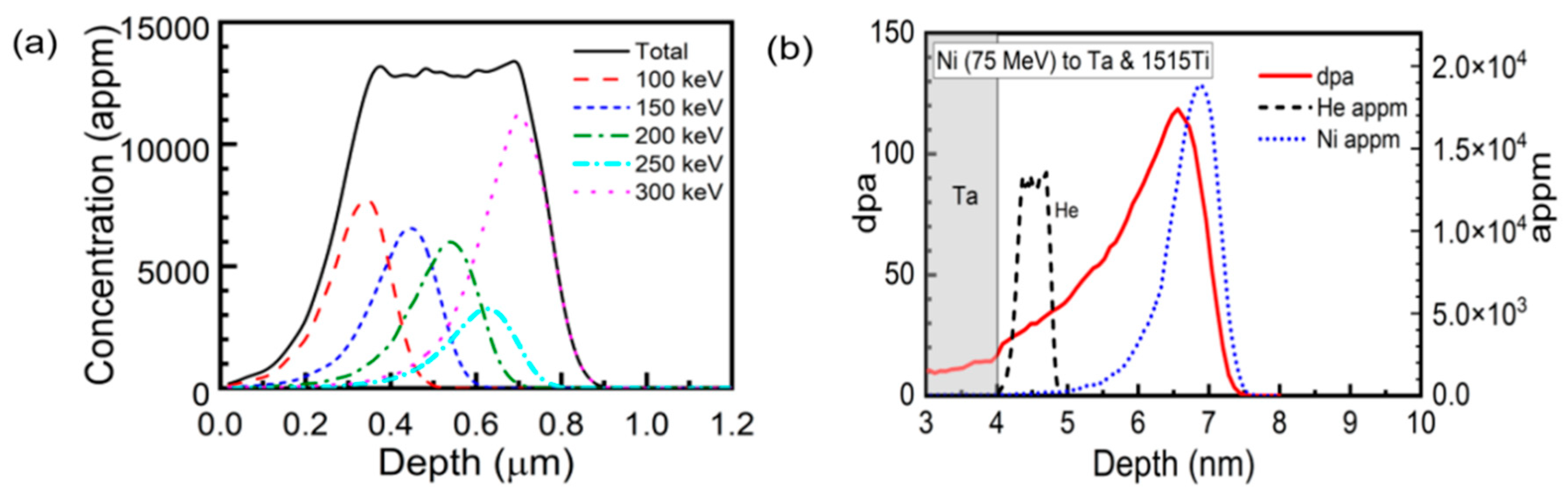
Figure 2.
TEM images and EELS measurement of 15-15Ti after irradiation to a peak dose of 120 dpa . (a) The overview image under bright field; (b) Dark field image under the STEM mode in the helium-implanted zone. The dose is about 30 dpa in this zone. The rectangle indicates the measured area by the EELS method; (c) The actual thickness of the area measured by EELS, given by multiplying the relative thickness from the EELS measurement with the mean free path of electrons. The rectangle of width 150 nm indicates the selected region of cavity measurements.
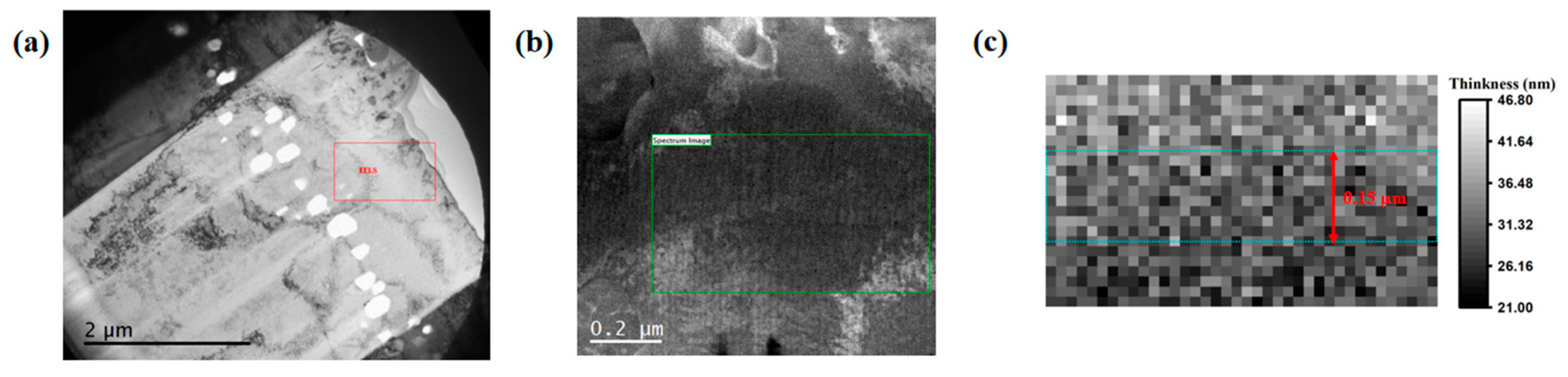
Figure 3.
Combined TEM image for specimen which the dose of helium implantation zone is 30 dpa. The red rectangle define the zone where the cavities are measured. The TEM images were rotated so that the horizontal axis is parallel to the projected surface of the specimen.
Figure 3.
Combined TEM image for specimen which the dose of helium implantation zone is 30 dpa. The red rectangle define the zone where the cavities are measured. The TEM images were rotated so that the horizontal axis is parallel to the projected surface of the specimen.
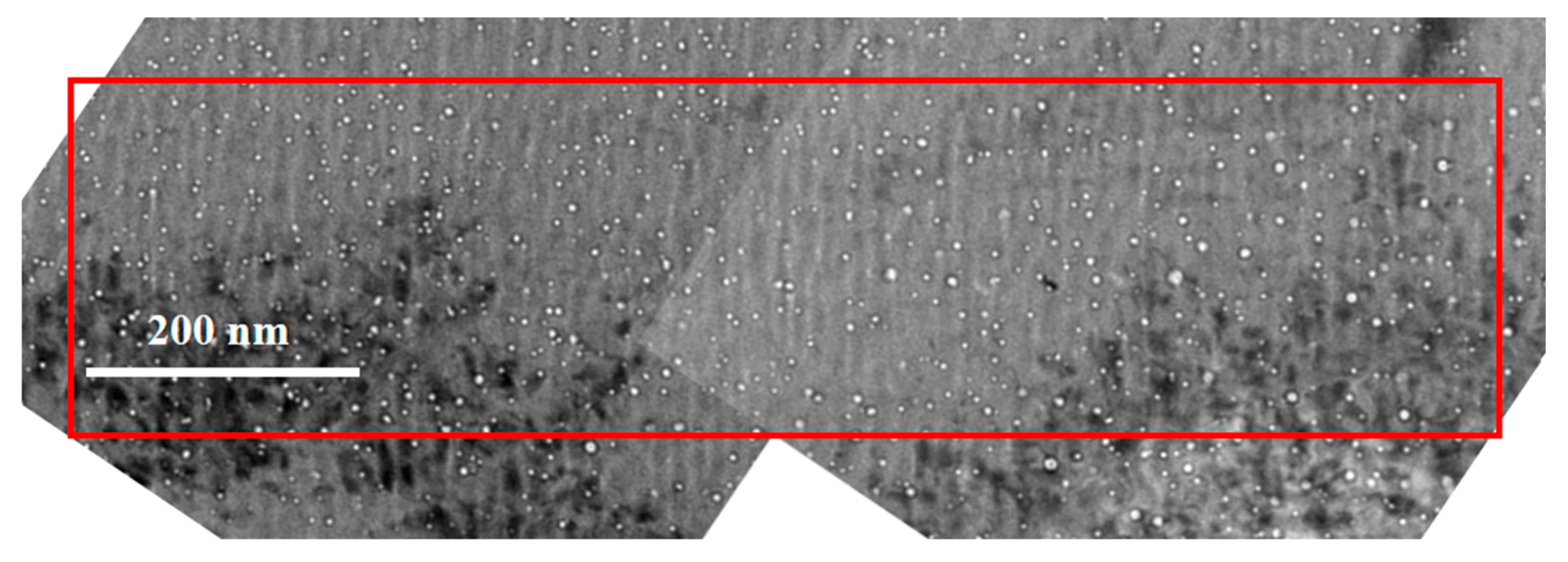
Figure 4.
A schematic drawing of ion injection into a material with normal and reduced densities.
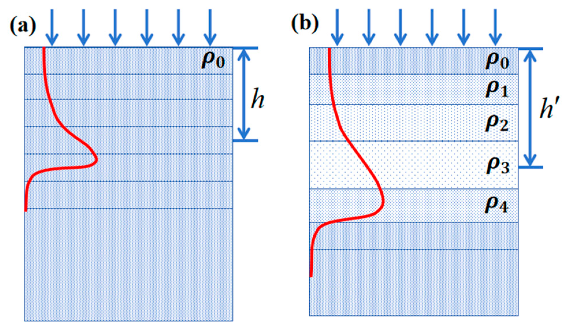
Figure 5.
Microstructure of 15-15Ti after irradiation at peak dose of (a) 120 dpa; (b) 240 dpa; (c) 400 dpa. They are overlapped with profiles of displacement damage (solid) and implanted Ni (dotted) and He (dashed). The damage curves as a function of depth in (b) and (c) were corrected due to the existence of extraordinarily large cavities. The microstructure in the helium-implanted zone were shown in (d-f) with doses of 30 dpa, 60 dpa, 122 dpa, respectively.
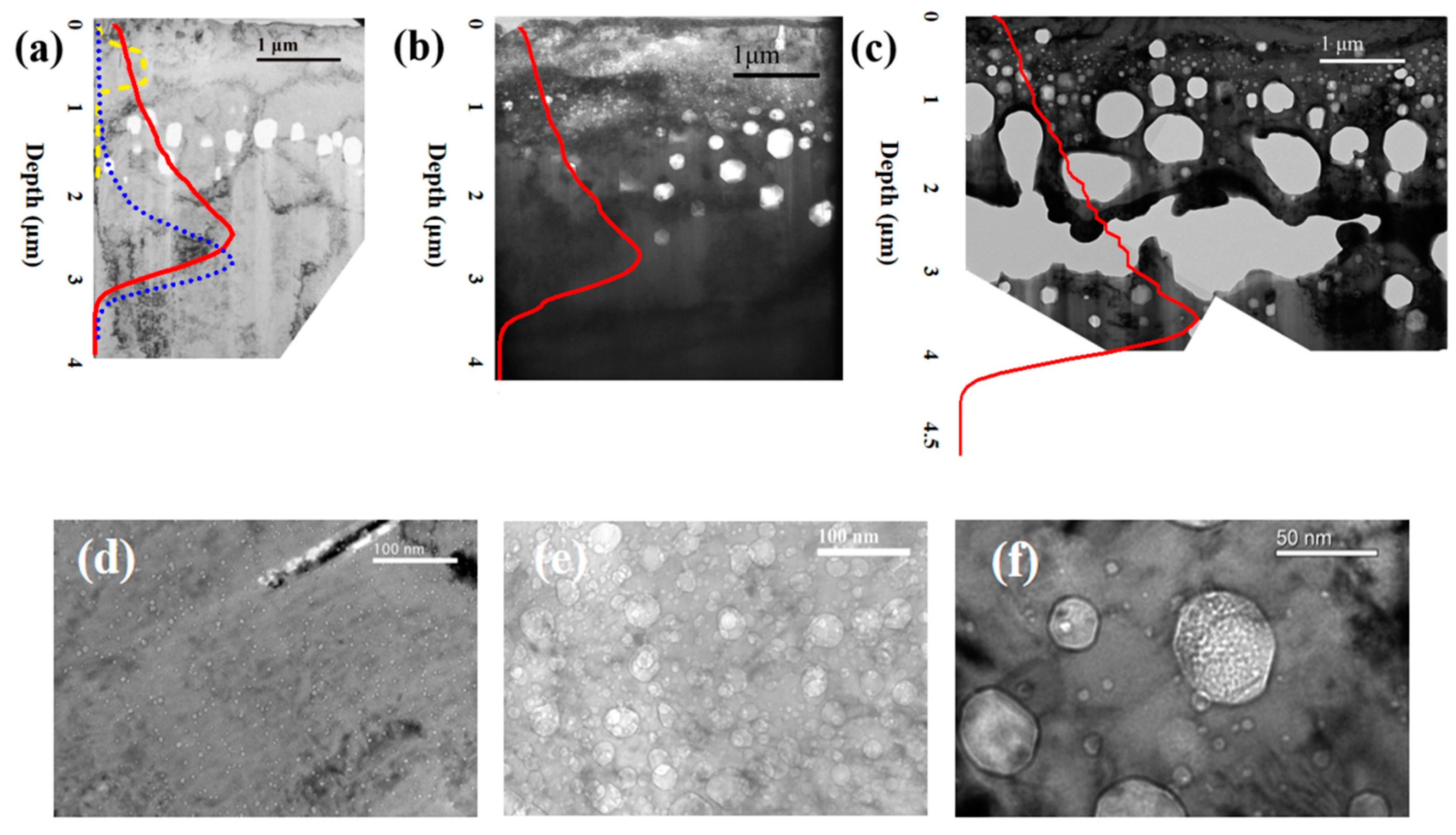
Figure 6.
Cavity size distribution in the helium-implanted zone.
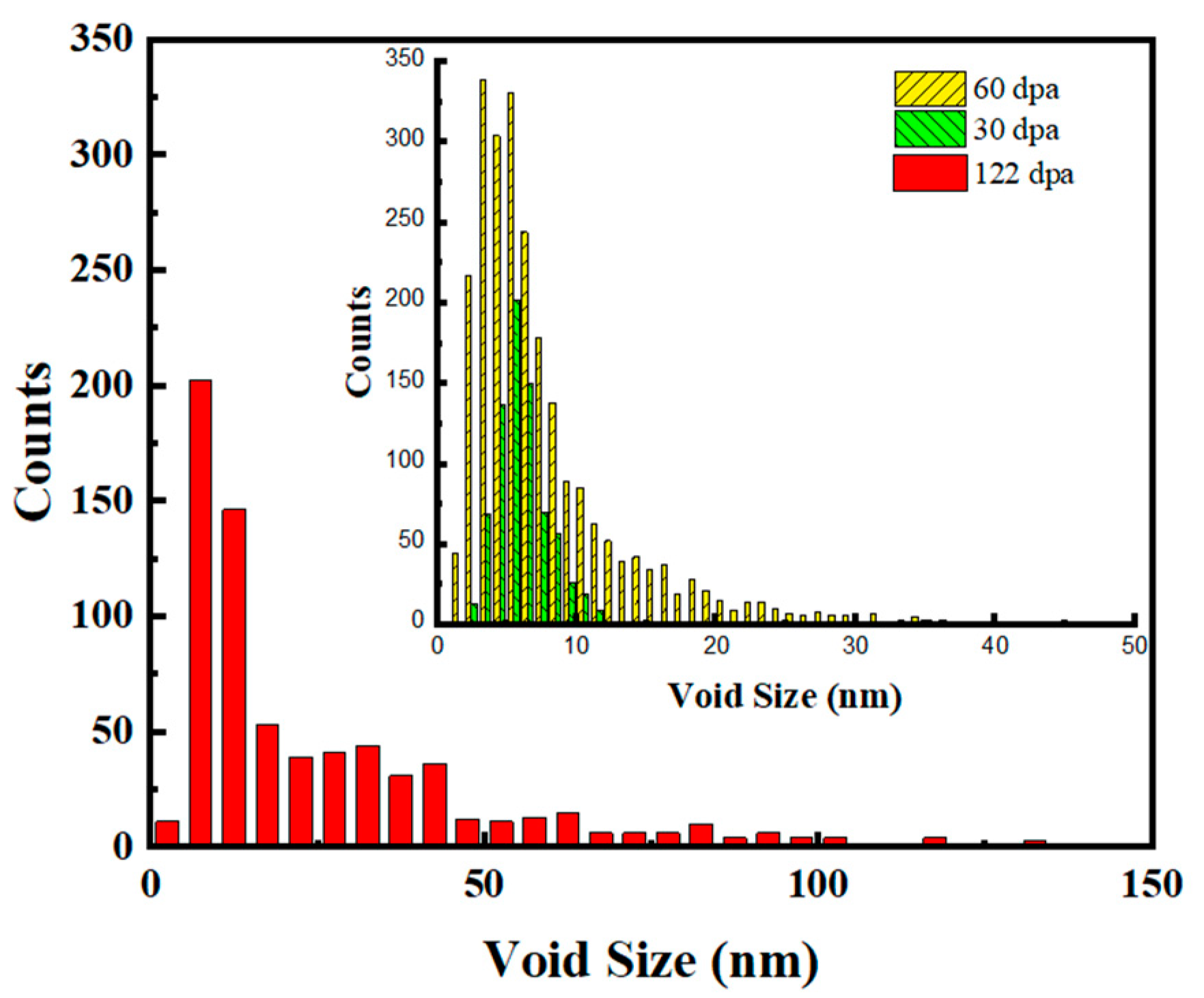
Figure 7.
Cavity densities in the helium-implanted zone.
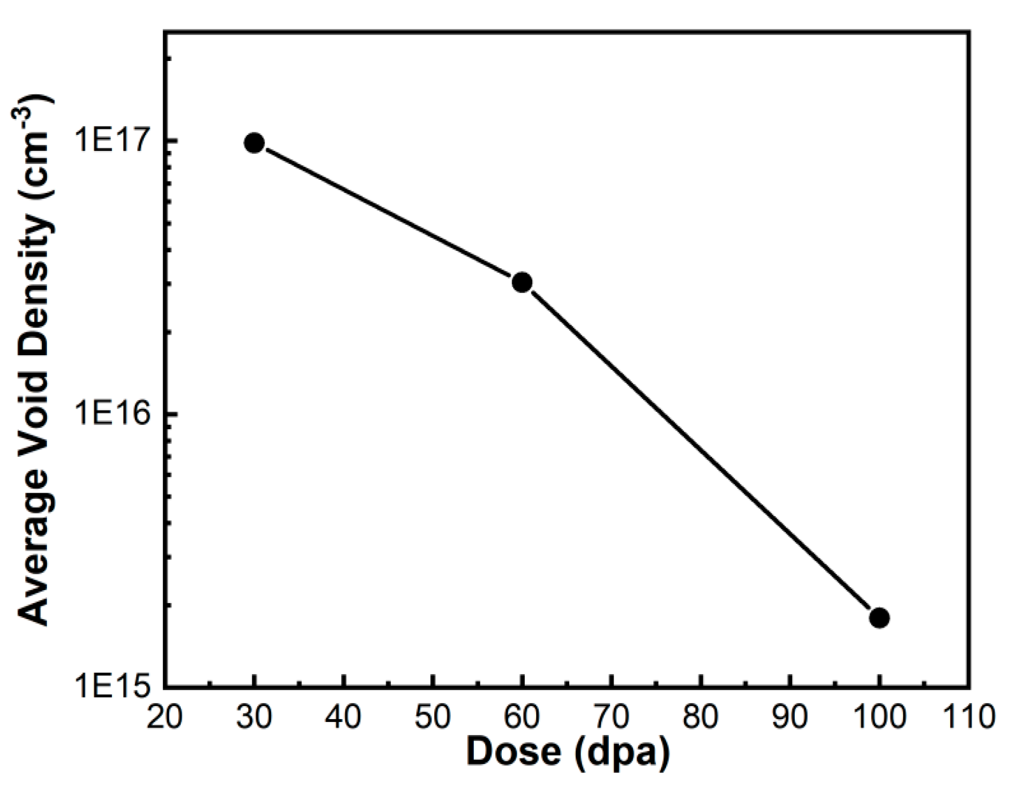
Figure 8.
Cavity swelling of He-implanted zone and near the damage peak region.
Disclaimer/Publisher’s Note: The statements, opinions and data contained in all publications are solely those of the individual author(s) and contributor(s) and not of MDPI and/or the editor(s). MDPI and/or the editor(s) disclaim responsibility for any injury to people or property resulting from any ideas, methods, instructions or products referred to in the content. |
© 2024 by the authors. Licensee MDPI, Basel, Switzerland. This article is an open access article distributed under the terms and conditions of the Creative Commons Attribution (CC BY) license (https://creativecommons.org/licenses/by/4.0/).
Copyright: This open access article is published under a Creative Commons CC BY 4.0 license, which permit the free download, distribution, and reuse, provided that the author and preprint are cited in any reuse.


