Submitted:
02 January 2024
Posted:
04 January 2024
You are already at the latest version
Abstract
Gesture recognition technology has been quickly developed in the field of human-computer interaction. The multiple-input multiple-output (MIMO) radar has been widely adopted in gesture recognition because of its notable spatial resolution. In this work, a highly accurate MIMO radar-based hand gesture recognition algorithm with very low complexity is proposed. To make the proposed system applicable in the industry and work well even when the size of the training data is limited, we applied several low-complexity adaptive signal processing methods to extract features and reduce the noise effect. First, spectrum analysis is applied to range-Doppler maps (RDMs) and a cell-averaging constant false alarm rate (CA-CFAR) with mirror filters is applied to improve the robustness to noise. Afterward, the features related to the distance, speed, direction, and the elevation angle of the moving object are determined by the proposed adaptive signal analysis techniques and the random forest is applied for classification. The proposed system has the capability to precisely distinguish and identify eight motions, including waving, moving to the left or right, patting, pushing, pulling, and rotating clockwise or anticlockwise, with an accuracy of 95%. Experiments demonstrate the capability of the proposed hand gesture recognition system to classify different movements precisely.
Keywords:
MIMO radar
; hand gesture recognition
; adaptive signal processing algorithm
; random forest
; mirror filtering
; elevation angle estimation
1. Introduction
The interaction between humans and computers is commonly referred to as human-computer interaction (HCI). Due to ongoing advancements in computer hardware and software, the field of HCI has experienced significant evolution. Different types of sensors are used in HCI, for example, mice, keyboards, touchscreens, cameras, Lidar, microphones, and RADAR. Due to its distinct attributes, radar is robust to external interference and light variation. Many research teams used radar information to perform hand gesture recognition. One of the most famous studies is the Soli project proposed by Google. With the use of several time analysis techniques, gesture recognition results with an accuracy of 92% could be achieved [1,2]. The radar technology employed in gesture recognition can be classified into different types, including continuous wave radar (CW), frequency-modulated continuous wave radar (FMCW), and multiple-input multiple-output (MIMO) [3]. More studies have been done in MIMO HCI which makes the most use of the massive volume of data.
Recently, several machine learning based hand gesture recognition algorithms were developed [11,12,18]. However, they frequently require large labeled training datasets and sophisticated computational architecture for improved precision. Furthermore, they usually need sophisticated hardware, such as GPUs, which limits their feasibility in resource-constrained scenarios. Therefore, in industry, handcrafted categorization techniques are still popular in gesture recognition. While the MIMO technology uses several antennas and channels simultaneously to achieve spatial diversity, we proposed a low computation and low energy classification method for radar-based hand gesture recognition.
In this paper, a highly accurate hand gesture recognition system with low complexity is proposed. It applies the range-Doppler map (RDM) to generate range parameters adaptively and uses the elevation angle information. Different from most of existing methods, which are mainly based on the neural network (NN), the proposed algorithm applies adaptive signal processing techniques for parameter assignment and uses smoothers and mirror filters to reduce the noise effect, and adopts the elevation angle information to improve the accuracy. Moreover, the random forest classifier is applied to achieve good performance even when the size of the training data is limited. With the proposed algorithm, eight unique hand gestures, including waving, moving to the left or right, patting, pushing, pulling, and rotating clockwise or anticlockwise, can be recognized accurately.
The proposed method is a low-complexity and augmented signal processing technique in conjunction with a high-resolution MIMO radar for classifying eight distinct hand gestures. This low-complexity approach demonstrates its efficacy by yielding remarkable results in gesture recognition, particularly in the scenario characterized by limited data availability. Experiments show that, with the proposed adaptive signal processing techniques together with the random forest classifier, an accuracy of 95% can be achieved, which is even better than the case where the NN is applied.
The structure of this article is as follows. The background and related work are reviewed in Section II. Section III provides a detailed illustration of each part of the proposed low-complexity hand gesture algorithm. Several experiments are conducted to evaluate the performance of the algorithm. A conclusion is made in Section V.
2. Preliminary
There are several existing radar-based hand gesture recognition methods, including the ones based on the CW radar [4,5], the FMCW radar [7,8,9,10,11,12,13,19], and MIMO [14,15,16].
Skaria et al. [4] used low-cost radar chips and advanced machine learning techniques. They used two-antenna Doppler radar to record the Doppler signatures of hand gestures and then trained a neural network. In [5], Wang et al. introduced an innovative approach to recognizing dynamic hand gestures by analyzing micro-Doppler radar signals using Hidden Gauss-Markov Models.
In 2022, Leu et al. [7] published a research using the RDM in a gesture detection system. They used the NN as the feature extractor. Zhao et al. [8] proposed a gesture detection system using the FMCW radar. They implemented the Blender software to generate different hand gestures and trajectories. They employed a two-dimensional Fast Fourier Transform (FFT), synthetic feature extraction, and a support vector machine (SVM), and achieved an average recognition accuracy of 89.13%.
With the adaptability of the spatial domain, there is an increase in the amount of research being done in MIMO HCI. Lei et al. [14] used the IWR1443 MIMO radar to generate the RDM and the range-azimuth map (RAM) in ten gestures, leveraging the data fusion technology coupled with the 3DCNN-LSTM network architecture. Zheng et al. [15] developed a transformer-based radar recognition network with the data frames of range-Doppler, range-angle, and range-elevation maps.
Besides using the neural network as a classifier, some researchers explored the use of simple classification methods to attempt gesture recognition. For example, the SVM was adopted in [8]. In [17], they aimed to determine five different emotions by calculating the relative positions of joints in the arms captured from the Kinect sensor and achieved an accuracy of 86.8%. Hao et al. [18] proposed a method with millimeter-wave near-field SAR imaging for wireless static gesture recognition. They used a histogram of oriented gradients for feature extraction and applied principal component analysis for dimensionality reduction. Tsang et al. [19] proposed a spiking neural network for radar-based hand gesture identification. They used different classifiers such as logistic regression, the random forest, and the SVM in the identification system.
3. Materials and Methods
This study outlines the creation of a specialized MIMO radar sensor designed to identify and analyze hand motions reliably. Figure 1 depicts a diagram of the proposed architecture. The radar captures comprehensive information from individuals engaging in hand gestures through its twelve virtual antennas. Following the data capture process, the gathered information is for further computation.
The classification of hand gestures is systematically partitioned into four distinct stages. Initially, the acquired data undergoes rigorous processing involving range and velocity computations facilitated by a two-dimensional Fast Fourier Transform (FFT). Subsequent stages encompass the application of a refined Constant False Alarm Rate mechanism and target detection algorithms, precisely delineating the pertinent variables associated with the spatial coordinates of the palm. The angle variable is determined using the Multiple Signal Classification (MUSIC) technique. After obtaining these parameters, feature extraction is performed and the obtained features are input into the Random Forest method for further analysis.
3.1. Range and Velocity Analysis
The combination of the MIMO radar together with the FMCW technology takes the advantages of the MIMO system in spatial diversity and the FMCW system in remarkable frequency modulation performance. The fusion leads to a highly adaptive, precise, and efficient radar system. Its detail is provided as follows. First, the radar transmits the chirp-modulated waveform through a transmitting antenna. It can be represented as,
where is the carrier frequency, is the sweep bandwidth of the chirp, and is the chirp duration. On the other hand, the received signal is the signal echoed from a target, which is a scaled and delayed version of the transmitted signal,
where is a scaled factor and is the delayed time. After that, the received signal is mixed with the transmitted signal to create an intermediate frequency signal:
where the beat frequency after the receive mixer is represented as . For static objects, the beat frequency is proportional to the distance, which is done by taking the fast Fourier transform (FFT) of the received IF signal. However, the velocity is determined for moving objects using phase change across multiple chirps. The phase and the frequency of the received signal changes with the velocity of the moving object. A second FFT is then applied across these chirps to extract the information about phase variation and velocities. This process yields a comprehensive 2D Range-Doppler map, providing valuable insights into the spatial distribution and velocity characteristics of detected objects.
Besides a traditional radar system with one single antenna transmitter, MIMO radar uses multiple antennas for transmission, which can create multidimensional arrays for spatial diversity. In our scenario, the physical antenna configurations with three transmitting antennas and four receivers can extended to 12 virtual antennas. The raw radar data is represented by a frame with three dimensions: ADC sampling, chirps, and antennas, as seen in Figure 2. The Fast Fourier Transform (FFT) is used in ADC sampling to extract ranges, also known as fast-time FFT or range-FFT. On the other hand, when a Fast Fourier Transform (FFT) is used to extract velocity information from chirp dimensions, it is called a slow-time FFT or Doppler-FFT, respectively. As depicted in Figure 2, by following the two-dimensional FFT, the Range-Doppler Map (RDM) is generated, providing accurate target range and velocity data. The hand motion can be represented based on the range and velocity differences observed in the frames of the RDM. The hand motion can be depicted by analyzing the variations in range and velocity recorded in the frames of the RDM. Therefore, in order to analyze the hand gesture, it was essential to determine the exact location of the hand in order to understand its motion before carrying out any more computations.
3.2. CFAR and Target Detection
When detecting the target, the background noise and other non-target signals will increase the difficulty of detecting the target afterwards. Therefore, in order to achieve reliable and consistent detection accuracy, a sensor needs to possess the capability of maintaining a constant false alarm rate (CFAR) with varying interference. The principle behind the CFAR is based on statistical and signal-processing concepts. It utilizes statistical information about the local background noise and adjusts the detection threshold based on this information to ensure a consistent false alarm rate across different conditions. This paper applies a cell-averaging (CA)-CFAR method to the algorithm, identifying a set of reference cells around the cell of interest and then computing the average power from the selected reference cell. The average over the threshold will be considered a target by setting a detection threshold.
After applying the CA-CFAR technique to the RDM, the frame has several peaks since the peak of the gesture is attributed to the human hands, arms, and body. Our hand gesture recordings ensure that the hand will always be at the front of the human body. It means the hand is the closest to the radar and makes the most velocity movement. Moreover, to acquire even more accurate hand gesture information from the radar, the following problems are addressed in the proposed system:
- Zero-Velocity Disturbances.
When analyzing the RDM for stationary objects, zero-velocity disturbances can introduce complexities in interpreting the data. One common source of zero-velocity disturbances is the presence of clutters or unwanted reflections from the environment, which remain after the CFAR. The clutter may be mistakenly viewed as real target movement. Thus, the proposed method incorporates an additional two-dimensional filter to differentiate between stationary and moving objects, thereby improving the precision of target identification and tracking. In order to obtain precise information from the radar and reduce these disturbances, incorporating an additional filter is a beneficial approach for radar system calibration.
- 2.
- Peaks caused by other body parts.
Due to the fact that the CA-CFAR threshold is determined by a fixed multiplier of the average power, the movement of other body parts may affect the result of hand motion detection. With this limitation caused by hardware architecture, the proposed method incorporates an additional step to address the error caused by body movement. This additional step is to identify the item with the highest velocity and the location with the greatest energy in the closest range to the radar. Focusing on these crucial measures enables us to identify the precise coordinates that correspond to the motion of the palm. This enhanced analysis enhances the ability of the radar system to detect complex motions.
- 3.
- The target velocity wrapping.
The determination of the target velocity is challenging when it surpasses the predetermined velocity range and returns to the opposite end of the velocity spectrum by wrapping or folding. In order to tackle this problem, we utilize the mirroring technique that is commonly used in the field of image processing. More precisely, we replicate the data in the initial three and final three columns, providing continuous variation of the speed while avoiding any kind of excessive computational complexity. Assume that the RDM is . Then the result after applying CA-CFAR is
where is the threshold factor and is the average reflectivity within a specific region. After that, we mirror the first and last three rows of the , which can be represented as
where is the number of rows in the matrix.
By implementing this mirrored technique, we successfully address the issue related to the target velocity beyond the specified range. This technique ensures the precise capture of the goal distance and the velocity trajectory while preserving the smoothness of the speed.
3.3. Angle of Arrival
In addition to determining the range and the velocity, the MIMO radar can also determine the angle between the radar and the target. By employing the direction of arrival (DoA), one can precisely identify the angles at which different items are positioned.
The MIMO radar system provides a large number of virtual antenna elements, which can reduce hardware requirements. If there exists a number of transceivers and receivers, and and represent the distance between antennas and the wavelength, respectively, then the angle resolution can be determined from
Equation (6) shows that the hardware structure still restricts the angle resolution. Therefore, we employ a Direction of Arrival (DoA) estimation approach to enhance the angle resolution.
The DoA data is helpful for calculating the degrees to which signals from reflected targets are received. By analyzing the DoA, one can determine the angles of the targets. DoA estimation can be classified into four main categories: beamforming, maximum likelihood, subspace-based methods, and compressive sensing. This paper utilized the well-known MUSIC method [20], which is a subspace-based method. It is based on using the eigenstructure of the data covariance matrix. Assume that the matrix of the received signals by one receive antenna is of size . Also suppose that transmission signals are and the noises are . Then, the received signals matrix at time can be written as
where is the steering matrix.
Since signals and noises are uncorrelated, the covariance matrix of is
where is the signal correlation matrix, is the noise variance, and is the identity matrix. Next, suppose that . Let and be the corresponding eigenvalues of the signal and noise eigenvectors, respectively. By the assumption in MUSIC, the steering vector of the signal is orthogonal to the subspace of noise, which can be written as
where is a column of matrix with . Then (5) can be represented as
with and . Then, the MUSIC spectrum is defined as
Meanwhile, by increasing the number of snapshots used for spectrum estimation, the ability of MUSIC to separate multiple targets can be further improved.
3.4. Elevation Calculation
To determine elevation angles precisely and reliably, an innovative method suitable for the IWR6843ISK radar system is proposed. It is designed with two antennas positioned at the same azimuth angle. As indicated by (6), this configuration results in a resolution angle of 45 degrees.
The structure of the radar system allows for the collection of four elevation angles using four antenna pairs. The possible location of the target is either on the upper side or the opposite side of the radar. Moreover, this additional layer improves the combination of data sources, thereby reducing the impact of the hardware limitation. In order to improve the accuracy, a voting mechanism is implemented. The voting system will determine the most possible elevation angle. This mechanism enhances the dependability of elevation angle estimation, resulting in a more precise depiction of data. Although limited by hardware, the proposed elevation angle determination algorithm is able to overcome the technological challenge and maintains the precision of the estimation result.
3.5. Data Smoothing and Feature Extraction
The hand position in each RDM was recorded and then used to determine the angle of hand motion. The MUSIC method was used to calculate the angle using the hand position data collected from eight antennas in the RDM. The elevation is determined by the method motioned above. As a result, we obtained the measurements for the range, the velocity, the azimuth, and the elevation angle of the dynamic hand movements in each frame.
Moreover, a data smoothing approach was applied due to the fluctuation of the detected range, velocity, and angle values. The moving average technique with window size three was utilized to enhance the precision of the data and reduce variations. This technique is helpful for improving the robustness to noise and enables a more organized interpretation of hand movements. Then, the detected range, velocity, and angle values are stored in a 4xn matrix , where each row represents each set of data:
Then, the moving average of T is computed:
Next, we created a set of features to improve the classification of different movements using different parts of the recorded data.
During feature extraction, we employ two methods to segment the data. One approach involves analyzing the data based on the total duration of object movement, while the other method entails dividing the data into eight equal segments for individual analysis. We extract a wide variety of parameters from the collected data in our study, which includes capturing the maximum and minimum values of the velocity and the azimuth angle, determining their ranges and distributions, and assessing the differences between the initial and final values of each parameter. We also determine the differences between these parameters and add the numbers in each part of the elevation angle. By incorporating these nuanced features, we aim to provide a comprehensive representation of the dynamic aspects of hand motions, which will be helpful for improving the accuracy of the later classification process.
3.5. Classification
In this work, the Random Forest algorithm has been used as the classification method. Although decision tree algorithms like C4.5, the classification and regression tree, ID3, and others are visually easy to understand, they are prone to noise and minor differences, increasing the chance of overfitting [22]. The Random Forest is a machine-learning ensemble technique that explicitly tackles these issues. During the training process, a significant number of decision trees are created, and each of them is built by randomly selecting a subset of features. Moreover, a voting method is utilized for the prediction of these trees afterward. The feature and sample selection variance improve the flexibility of the model, reduce the likelihood of overfitting, and enhance its generalization ability.
4. Results and Discussion
4.1. Radar System Configuration
In experiments, the Texas Instruments IWR6843 millimeter wave (mmWave) radar board and the Texas Instruments DCA1000 data acquisition adaptor were utilized. The radar board is equipped with four transmitters and three receivers that function within the frequency range of 60-64 GHz. This setup enables outstanding range and velocity resolution. To create a virtual array for measuring the azimuth angle and the elevation angle, a setup with three transmitters and four receivers was utilized, resulting in a total of 12 antennas. Signals produced by a synthesizer were distributed via the two transmitters. Meanwhile, four receivers captured the signal after it was reflected from the target.
4.2. Building Gesture Dataset
The algorithm was performed offline. The data set was collected by our lab. It consists of eight dynamic movements, each accompanied by corresponding RDM images from different receive channels. The movements and their visual representations are explained as follows:
- Wave (W) – The palm waves for two cycles.
- Left (L) – The palm swipes from left to right
- Right (R) – The palm swipes from right to left
- Pat (P) – The palm moves back and forth rapidly for two cycles.
- Push (PS) – The palm pushes forward
- Pull (PL)– The palm pulls away
- Clockwise (C) – The palm draws a clockwise circle in the air
- Anti-Clockwise (AC) – The palm draws an anti-clockwise circle in the air
4.2. Radar Image Examples
The dynamic movements are recorded and analyzed to identify specific features such as the range, the velocity, and the angle.
The palm is served as the region of motion and its coordinates are determined by the strongest signal in each frame. Figure 3 illustrates the pattern of the palm movement throughout time, and each gesture in the RDM is characterized by a unique hand movement. During the push (PS) action, the target moves upwards towards the top of the RDM, whereas during the pull (PL) action, it travels away from the RDM. On the right side of Figure 3, how distance and velocity vary with time is depicted. These variations prominently reveal the motion patterns to be recognized. For instance, when performing a wave (W) motion, there is a periodic variation in speed; when executing a pat (P) gesture, there is a periodic change in both distance and velocity. In addition, 'push' and 'pull' exhibit distinctive characteristics in distance and velocity variations. However, to well distinguish other motions, other factors like the angle should also be considered.
In the proposed algorithm, the angle value is added as a parameter to differentiate between various movements. Figure 4 illustrates the instances of the distributions of different hand movements in the range-angle domain. It is also noticeable that both left and right movements exhibit lateral displacement, whereas 'pat', 'push' and 'pull' are characterized by vertical motion. However, distinguishing between clockwise and counterclockwise movements is more complex solely based on these graphs. Consequently, we turn to analyze these eight gestures through additional defined parameters.
4.3. Gesture Recognition Performance Analysis
The experimental hand-gesture data consists of inputs from five separate right-handed persons, all of whom followed the exact instructions to perform and repeat 25 iterations of eight motions. This resulted in a total of 125 instances for each gesture. For data collection, a total of 100 frames were captured for each gesture, with participants positioned at a distance of roughly one meter from the radar sensor.
For the classification, the Random Forest algorithm was utilized using a 5-fold cross-validation method, adopting an 80%-20% split between training and validation data. The adopted random forest architecture is configured with 20 trees in the ensemble. The training dataset consists of 100 sequences, while the testing dataset has 25 sequences. The confusion matrix that resulted from the analysis of the suggested approach is depicted in Figure 5. The Random Forest method resulted in an overall accuracy rate of 95%. The left (L) gesture, in particular, demonstrated a significantly high accuracy of approximately 99%, making it distinctly recognizable.
Table 1 and Table 2 presents a comparison analysis using the Support Vector Machine (SVM) with one versus one technique, the K-Nearest Neighbors (KNN) algorithms with k set to five, and the NN methods apply the feedforward technique with 50 epochs.
The extended computational duration of the SVM is related to its architecture. During the training phase, the SVM undertakes a complicated procedure to choose the most proper hyperplane that effectively distinguishes various classes in the feature space, which results in a slower training speed. The low efficiency of the NN can be linked to the shortage of training data, reducing the capacity to learn an effective classifier due to the lack of diverse and representative examples. Moreover, its extended training duration is not suitable for the intended purpose. Among four approaches, the suggested approach can achieve the highest accuracy with less training and test times, highlighting its effectiveness in precisely categorizing hand movements. These results demonstrate the efficacy and proficiency of the suggested hand gesture recognition framework.
5. Conclusions
In this work, an accurate and efficient radar-based hand gesture recognition system was proposed. The data was acquired from the radar equipped with twelve virtual antennas. It was then processed by range and velocity calculations utilizing a 2D-FFT. Moreover, the modified CA-CFAR with mirror filters and target detection algorithms were also adopted to enhance the robustness. The azimuth angle variable was determined via the MUSIC method. Then, an improved way for elevation angle computation was also proposed. Next, the defined parameters were determined adaptively, subjected to feature extractors, and fed into the Random Forest system. The confusion matrix showed that the proposed gesture classification algorithm is robust, with each gesture reaching over 93% accuracy and an average of 95% overall accuracy across five folds. This result demonstrated the effectiveness of the proposed algorithm in accurately differentiating between eight movements. Additionally, the system performed exceptionally well without requiring a large dataset or a complicated training process, highlighting its efficiency and applicability in gesture detection applications in the industry.
Author Contributions
Conceptualization, T.J.T. and J.J.D.; methodology, T.J.T.; software, T.J.T.; validation, T.J.T.; formal analysis, T.J.T. and J.J.D.; investigation, T.J.T.; resources, T.J.T.; data curation, T.J.T.; writing—original draft, T.J.T.; writing—review and editing, T.J.T. and J.J.D.; visualization, T.J.T.; supervision, J.J.D.; project administration, J.J.D.; funding acquisition, J.J.D. All authors have read and agreed to the published version of the manuscript.
Funding
This research work was funded by National Science and Technology Council, Taiwan, R.O.C., grant number MOST 110-2221-E-002 -092 -MY3.
Institutional Review Board Statement
Not applicable.
Informed Consent Statement
Not applicable.
Data Availability Statement
Not applicable.
Conflicts of Interest
The authors declare no conflict of interest.
References
- Lien, J.; Gillian, N.; Karagozler, M.E.; Amihood, P.; Schwesig, C.; Olson, E.; Raja, H.; Poupyrev, I. Soli: Ubiquitous gesture sensing with millimeter wave radar. ACM Trans. Graph. TOG 2016, 35, 1–19. [Google Scholar] [CrossRef]
- Hayashi, E.; Lien, J.; Gillian, N.; Giusti, L.; Weber, D.; Yamanaka, J.; Bedal, L.; Poupyrev, I. RadarNet: Efficient Gesture Recognition Technique Utilizing a Miniature Radar Sensor. In Proceedings of the 2021 CHI Conference on Human Factors in Computing Systems (CHI '21); ACM: New York, NY, USA, 2021; Volume 5, pp. 1–14. [Google Scholar]
- Ahmed, S.; Kallu, K.D.; Ahmed, S.; Cho, S.H. Hand Gestures Recognition Using Radar Sensors for Human-Computer-Interaction: A Review. Remote Sens. 2021, 13, 527. [Google Scholar] [CrossRef]
- Skaria, S.; Al-Hourani, A.; Lech, M.; Evans, R.J. Hand-Gesture Recognition Using Two-Antenna Doppler Radar With Deep Convolutional Neural Networks. Sensors 2019, 19, 3041–3048. [Google Scholar] [CrossRef]
- Wang, Z.; Li, G.; Yang, L. Dynamic Hand Gesture Recognition Based on Micro-Doppler Radar Signatures Using Hidden Gauss–Markov Models. IEEE Geosci. Remote Sens. Lett. 2021, 18, 291–295. [Google Scholar] [CrossRef]
- Yu, M.; Kim, N.; Jung, Y.; Lee, S. A Frame Detection Method for Real-Time Hand Gesture Recognition Systems Using CW-Radar. Sensors 2020, 20, 2321. [Google Scholar] [CrossRef] [PubMed]
- Jhaung, Y.-C.; Lin, Y.-M.; Zha, C.; Leu, J.-S.; Köppen, M. Implementing a Hand Gesture Recognition System Based on Range-Doppler Map. Sensors 2022, 22, 4260. [Google Scholar] [CrossRef] [PubMed]
- Zhao, Y.; Sark, V.; Krstic, M.; Grass, E. Low Complexity Radar Gesture Recognition Using Synthetic Training Data. Sensors 2022, 23, 308. [Google Scholar] [CrossRef]
- Shen, X.; Zheng, H.; Feng, X.; Hu, J. ML-HGR-Net: A Meta-Learning Network for FMCW Radar Based Hand Gesture Recognition. Sensors 2022, 22, 10808–10817. [Google Scholar] [CrossRef]
- Scherer, M.; Magno, M.; Erb, J.; Mayer, P.; Eggimann, M.; Benini, L. TinyRadarNN: Combining Spatial and Temporal Convolutional Neural Networks for Embedded Gesture Recognition With Short Range Radars. IEEE Internet of Things J. 2021, 8, 10336–10346. [Google Scholar] [CrossRef]
- Sharma, R.R.; Kumar, K.A.; Cho, S.H. Novel Time-Distance Parameters Based Hand Gesture Recognition System Using Multi-UWB Radars. IEEE Sens. Lett. 2023, 7, 1–4. [Google Scholar] [CrossRef]
- Mao, Y.; Zhao, L.; Liu, C.; Ling, M. A Low-Complexity Hand Gesture Recognition Framework via Dual mmWave FMCW Radar System. Sensors 2023, 23, 8551. [Google Scholar] [CrossRef] [PubMed]
- Lee, H.R.; Park, J.; Suh, Y.-J. Improving Classification Accuracy of Hand Gesture Recognition Based on 60 GHz FMCW Radar with Deep Learning Domain Adaptation. Electronics 2020, 9, 2140. [Google Scholar] [CrossRef]
- Lei, W.; Jiang, X.; Xu, L.; Luo, J.; Xu, M.; Hou, F. Continuous Gesture Recognition Based on Time Sequence Fusion Using MIMO Radar Sensor and Deep Learning. Electronics 2020, 9, 869. [Google Scholar] [CrossRef]
- Zheng, L.; Bai, J.; Zhu, X.; Huang, L.; Shan, C.; Wu, Q.; Zhang, L. Dynamic Hand Gesture Recognition in In-Vehicle Environment Based on FMCW Radar and Transformer. Sensors 2021, 21, 6368. [Google Scholar] [CrossRef] [PubMed]
- Xia, Z.; Xu, F. Time-Space Dimension Reduction of Millimeter-Wave Radar Point-Clouds for Smart-Home Hand-Gesture Recognition. IEEE Sens. J. 2022, 22, 4425–4437. [Google Scholar] [CrossRef]
- Saha, S.; Datta, S.; Konar, A. Decision Tree-Based Single Person Gesture Recognition. In Proceedings of the 2019 International Conference on Soft Computing for Problem Solving (SocProS) (2019). [Google Scholar]
- Hao, Z.; Wang, R.; Peng, J.; Dang, X. Static Hand Gesture Recognition Based on Millimeter-Wave Near-Field FMCW-SAR Imaging. Electronics 2023, 12, 4013. [Google Scholar] [CrossRef]
- Tsang, I.J.; Corradi, F.; Sifalakis, M.; Van Leekwijck, W.; Latré, S. Radar-Based Hand Gesture Recognition Using Spiking Neural Networks. Electronics 2021, 10, 1405. [Google Scholar] [CrossRef]
- S chmidt, R. Multiple Emitter Location and Signal Parameter Estimation. IEEE Trans. Antennas Propag. 1986, 34, 276–280. [Google Scholar] [CrossRef]
- Texas Instruments Corp. MIMO Radar. Available online: https://www.ti.com/lit/an/swra554a/ swra554a.pdf (accessed on 20 December 2023).
- Somvanshi, M.; Chavan, P.; Tambade, S.; Shinde, S.V. A Review of Machine Learning Techniques Using Decision Tree and Support Vector Machine. In Proceedings of the 2016 International Conference on Computing Communication Control and Automation (ICCUBEA), Pune, India (2016). [Google Scholar]
- Texas Instruments Corp. mmWave Radar for Automotive and Industrial Applications. Accessed Dec. 20, 2023. Available online: https://www.ti.com/content/dam/videos/external-videos/2/3816841626001/5675916489001.mp4/subassets/Mmwave_webinar_ Dec2017.pdf.
Figure 1.
The overview of the proposed hand gesture recognition.
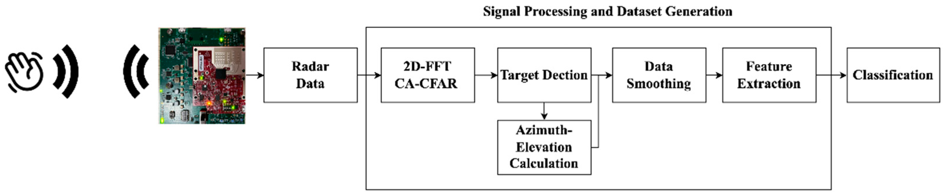
Figure 2.
Radar signal pre-processing for the RDM.

Figure 3.
The range-Doppler map with gestures through frames. (a) Wave; (b) Left; (c) Right; (d)Pat; (e) Push; (f) Pull; (g) Clockwise; (h)Anti-Clockwise.
Figure 3.
The range-Doppler map with gestures through frames. (a) Wave; (b) Left; (c) Right; (d)Pat; (e) Push; (f) Pull; (g) Clockwise; (h)Anti-Clockwise.
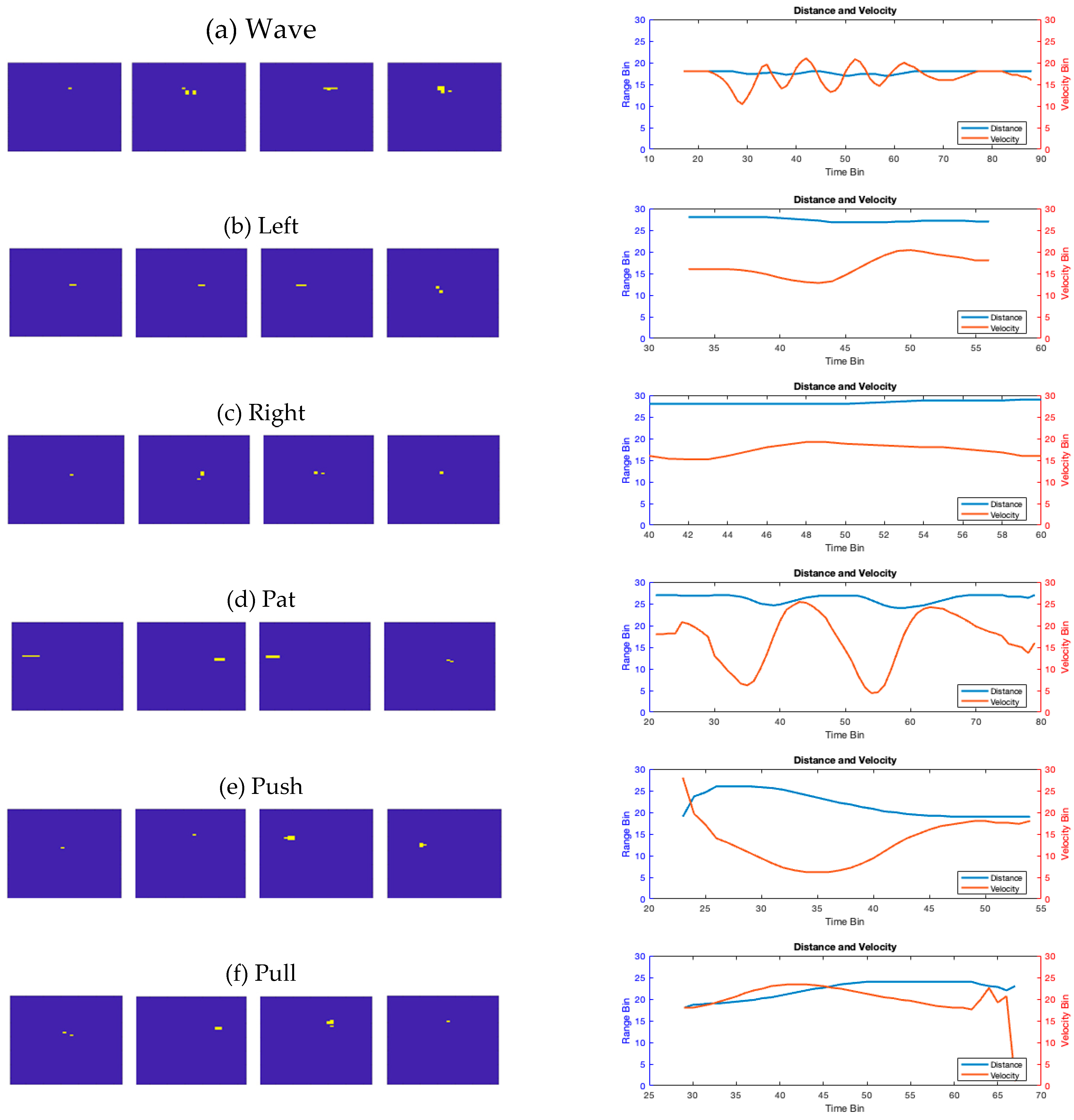
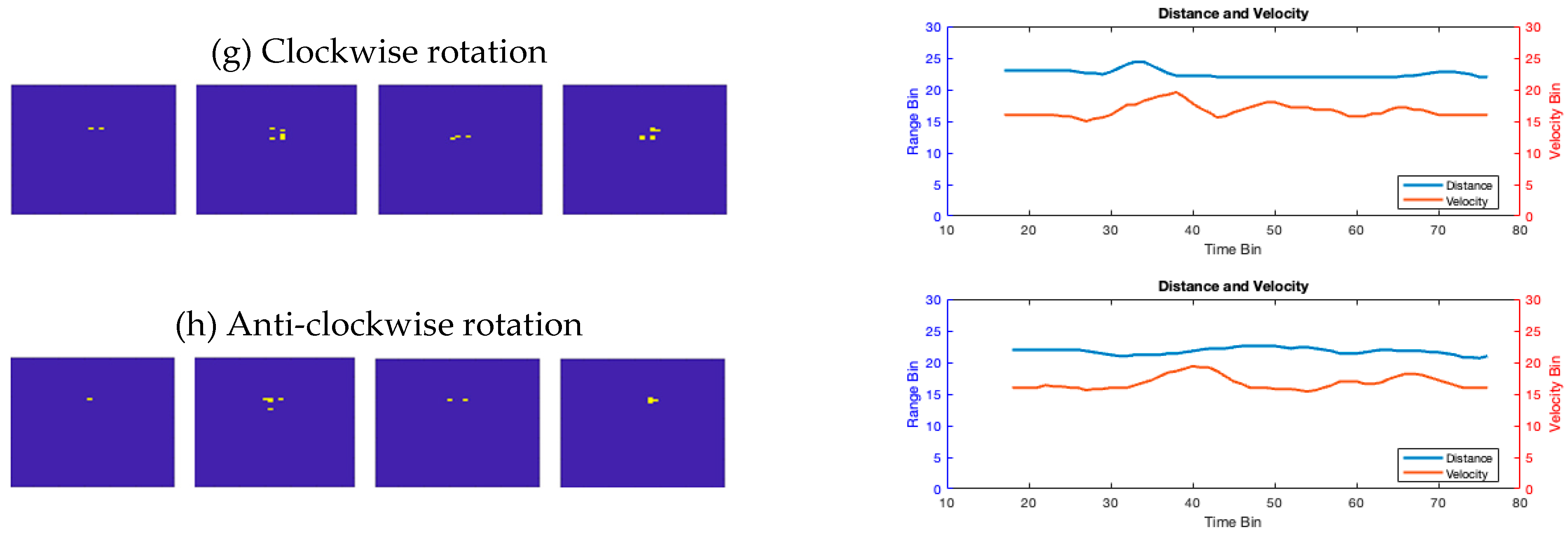
Figure 4.
The range-angle in polar plot with different gestures. (a) Wave; (b) Left; (c) Right; (d)Pat; (e) Push; (f) Pull; (g) Clockwise; (h)Anti-Clockwise. .
Figure 4.
The range-angle in polar plot with different gestures. (a) Wave; (b) Left; (c) Right; (d)Pat; (e) Push; (f) Pull; (g) Clockwise; (h)Anti-Clockwise. .
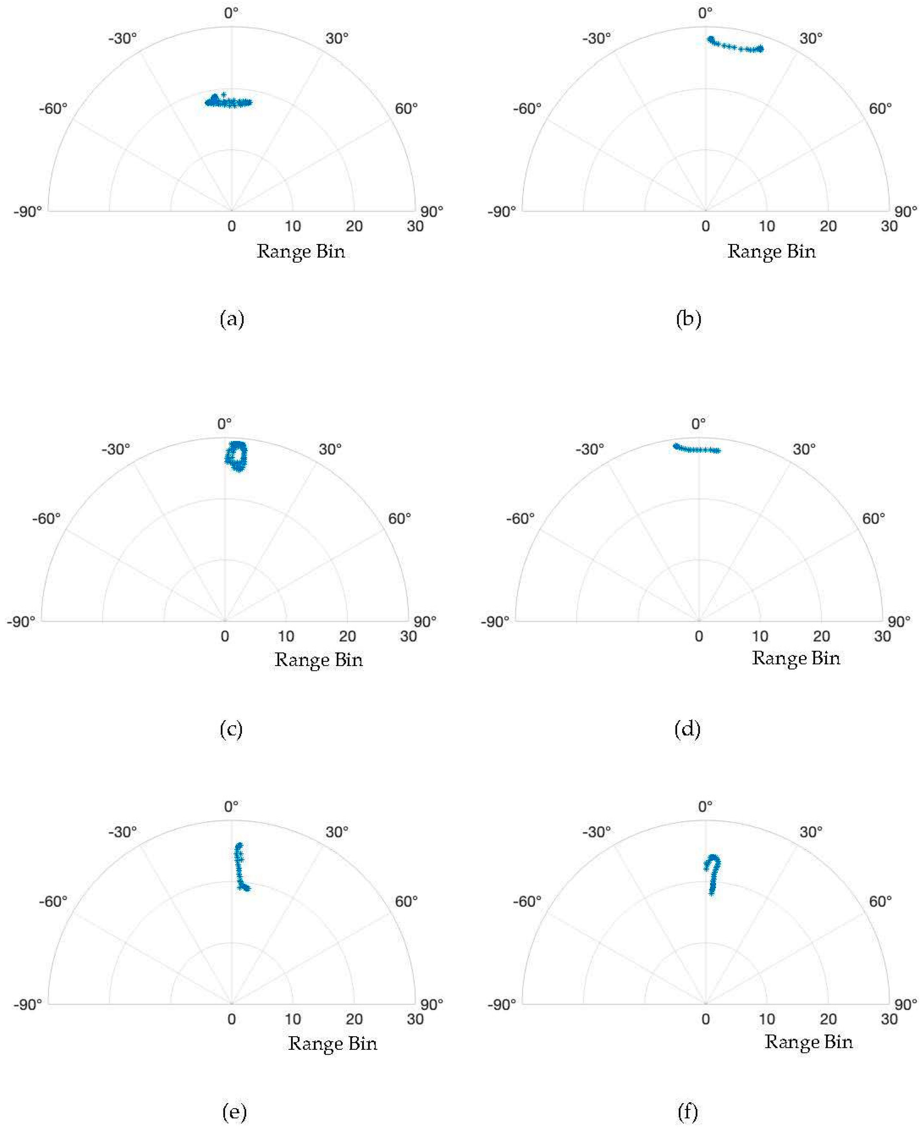
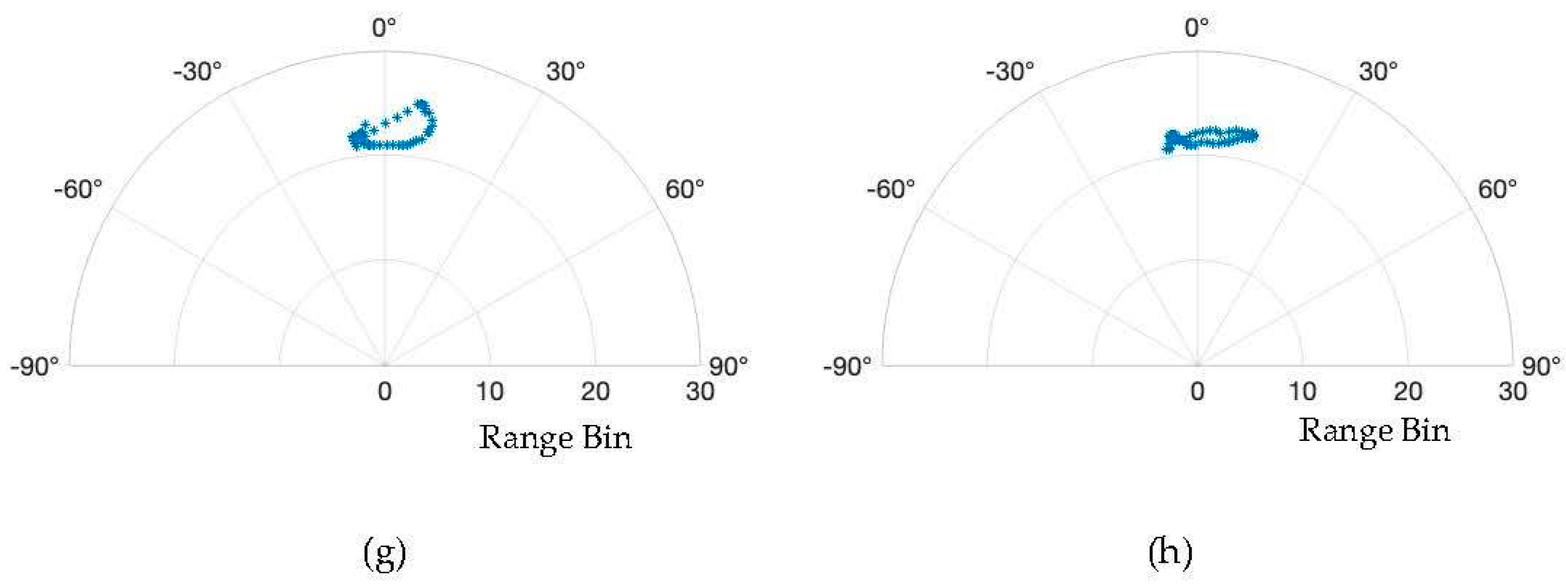
Figure 5.
The confusion map using the proposed algorithm.
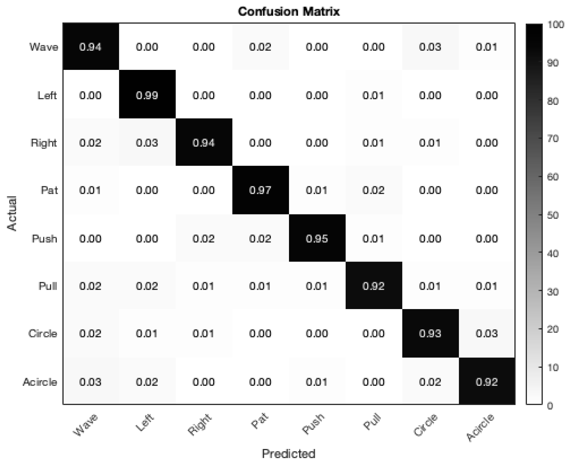

Table 1.
Recognition Accuracy comparison for each method. .
| Method | W | L | R | P | PS | PL | C | AC |
|---|---|---|---|---|---|---|---|---|
| SVM | 99 | 98 | 91 | 99 | 95 | 91 | 91 | 90 |
| KNN | 90 | 98 | 92 | 95 | 94 | 88 | 81 | 92 |
| NN | 96 | 88 | 88 | 92 | 96 | 88 | 80 | 92 |
| Proposed | 94 | 99 | 94 | 97 | 95 | 92 | 93 | 92 |
Table 2.
Recognition Accuracy comparison for each method with time.
| Method | Accuracy | Training Time | Testing Time |
|---|---|---|---|
| SVM | 95% | 0.17 s | 0.013 s |
| KNN | 91% | 0.03 s | 0.005 s |
| NN | 90% | 2.76 s | 0.021 s |
| Proposed | 95% | 0.07 s | 0.012 s |
Disclaimer/Publisher’s Note: The statements, opinions and data contained in all publications are solely those of the individual author(s) and contributor(s) and not of MDPI and/or the editor(s). MDPI and/or the editor(s) disclaim responsibility for any injury to people or property resulting from any ideas, methods, instructions or products referred to in the content. |
© 2024 by the authors. Licensee MDPI, Basel, Switzerland. This article is an open access article distributed under the terms and conditions of the Creative Commons Attribution (CC BY) license (http://creativecommons.org/licenses/by/4.0/).
Copyright: This open access article is published under a Creative Commons CC BY 4.0 license, which permit the free download, distribution, and reuse, provided that the author and preprint are cited in any reuse.


