Submitted:
30 December 2023
Posted:
04 January 2024
You are already at the latest version
Abstract
The human-centric approach is a leading trend for future production processes, and collaborative roboticists are key to its realization. This article addresses the challenge of designing a new cus-tom-made non-conventional machine or robot involving toolpath control (interpolated axes) with collaborative functionalities but by using “general-purpose standard" safety and motion control technologies. This is done on a non-conventional Cable-Driven Parallel Robot (CDPR). Safety is assured by safe commands to individual axes, known as Safe Motion Monitoring Functionalities, which limits the axes speed in the event of human intrusion. At the same time, the robot's Motion Controller applies an override to the toolpath speed to accommodate the robot's path speed to the axis’s limitations. The implementation of a new Pre-Warning Zone, prevent unnecessary stops due to the approach of the human operator. The article also details a real experiment that validates the effectiveness of the proposed strategy.
Keywords:
Collaborative CDPR
; Industrial safety
; Motion control
; Motion control Safety
; Industrial Automation Safety Trends
; Collaborative Robotics
1. Introduction
1.1. New trends in non-conventional industrial robots
Industrial applications with several axes working in a coordinated way to perform trajectories are expanding their application range beyond the traditional machining systems (CNC) and conventional industrial robotics [1,2]. From packaging processes to new flexible production lines, they often incorporate toolpath operations into their workflows [3]. Significant advances in machine automation and industrial motion control technologies have driven this expansion. Consequently, industrial machinery designers are increasingly adopting servo drive technology [4], along with new mechatronic resources, to meet the demanding flexibility and performance needs of modern factories [5]. Current general-purpose motion control technologies are enabling not just simple movements, but also the execution of complex, flexible kinematic relationships among different mechanical components of machines. The emergence of fast, deterministic, and synchronous digital networks has facilitated the connection of multiple motors to a single controller. Often, servo technology is being chosen over the traditional large single-motor setup, centralizing functionalities within the machine and replacing mechanical systems with software-based control. This approach is commonly known as a “mechatronic solution”[6].
1.2. Conventional collaborative automation architectures
Parallel to the development of industrial servo technology, which is the basis for motion control machinery and industrial robots, the latest industry safety regulations facilitate the conception of new advanced machinery with complex interaction with human operators. Specifically for servo-actuated machines, there has been an expansion of safety regulations designed to facilitate their safe and even collaborative operation [10].
In conventional collaborative robotics, specific standards clearly define safe operation practices, allowing for a reduction in the physical separation traditionally required between humans and hazardous processes, as stated in ISO 12100 [11]. However, except in the exceptional case where a collaborative robot, for constructional reasons, can be considered as an inherently safe machine, it is mostly to be regarded as just another very specialized output device (Safety Related System/Control System: SRC/CSc) in the safety chain [12]. Transferring equivalent collaborative functionalities to general-purpose machinery must deal with the complexities of universal safety regulations and the standard safety features of general automation technologies. For example, ISO 12100 also specifies the need to carry out a risk assessment when designing a new machine, as well as the risk reduction process required for risks that cannot be significantly reduced by redesigning the machine. Other standards, such as those detailing Performance Levels (PL) [13] and Safety Integrity Levels (Sil) [14], guide the design of safety-related control system components. These standards have opened the possibility of using electronically programmed technology to make safety-related decisions. However, it remains a fundamental principle of safety implementation that logic—whether simple or complex—must be managed by devices certified for that purpose. PLCs (Programmable Logic Controllers), CNCs (Computer Numerical Controllers), and general-purpose motion controllers are not.
Therefore, a two-layer decision or logic architecture is required. Figure 1 shows the two levels of hardware and software that are mandatory in industrial machinery (according to ISO 13849-1 [13]): the safety subsystem, also called the Safety Related System/Control System, which includes inputs, logic, safe actuation, and communications; and the operational subsystem, which comprises standard inputs, process logic, standard actuation, and standard communications. Each one makes their own decisions, although they can exchange information to qualify or parameterize their logic.
1.3. Collaborative for non-standard robotics: Collaborative CDPRs.
Collaborative robotics development must go beyond conventional industrial robots to include other kinds of robotic configurations that may offer functional advantages compared to the more common industry configurations, and that may cover application scenarios where conventional industrial robots are overly specialized. CDPRs are one such alternative configuration. The study and conceptualization of collaborative behavior in CDPRs is a novel and little-addressed research issue. Most approaches focus on achieving low stiffness during motion. This low stiffness enables the CDPR to absorb energy induced during a collision, thereby preventing damage to both the CDPR and the collided object or body part [15]. This has been addressed in different ways, for example, through auxiliary mechanisms attached to the cables [16] or by using architectures with Degrees of Freedom (DOFs) operated redundantly to achieve a controllable stiffness [17]. The impact of a CDPR stiffness on its transparency, which is the robot's ability to move in the direction intended by the user, during co-manipulation tasks involving human-robot interaction is also explored [18]. Other researchers contributed to collaborative CDPR focusing on managing cable interferences and collision detection methods when a human-CDPR physical interaction is needed [19,20]. Additional researchers also contributed to the field by proposing and evaluating advanced control strategies aimed at enhancing physical human-robot collaboration [21].
However, most initiatives overlook the industrial-implementation “standard and normative” issues. As depicted in Figure 1, a general-purpose industrial motion control system architecture has a two-layer structure with two decision elements: the safety controller and the motion controller.
On one hand, the safety logic generates commands for the servo-axes. Although industrial safety standards have addressed the definition of machine servo axis's safety operating modes in detail, they do it considering the axes individually. They have not considered the implications for the toolpath when these axes are coordinated to operate as a group. This limitation has the origin in the safety standards themselves, which force that the decision-making architecture must separate safety decisions from toolpath control. As a result, safety decisions require dedicated hardware and software that have the corresponding certifications.
On the other hand, only the motion controller has all the necessary information to make decisions concerning the toolpath. The individual motion control of each axis depends on the controller, namely its "numerical control task", which generates the setpoints for each axis via its servo drive. However, the servo drives do not know whether they are working alone, for example performing a point-to-point movement, or in coordination with other axes to execute an interpolated movement.
The article addressed the objective of implementing a smooth toolpath movement despite this two-level general-purpose decision architecture when implementing collaborative operation-Speed and Separation Monitoring (SSM)-in general-purpose machinery. It further explores the issues related to toolpath speed limitations that arise when human operators and robots share a workspace, alongside the independent role of the safety controller in issuing speed-limiting commands to each axis. This is done on a non-conventional robot (CDPR), which is presented in the next section (section 2.1). Section 2 also reviews the safety standards for collaborative robots as well as the integration of safety architectures within collaborative operations. Section 3 outlines the toolpath control implemented for the CDPR. Section 4 analyzes an SSM implementation strategy for a CDPR prototype through three use cases: a regular toolpath without human interference, the simultaneous application of SLS and toolpath override, and a new Pre-Warning Zone for smoother toolpath override. This subsystem operates independently to restrict the kinematic parameters of the axes for safety. The developed strategy can be applicable to any robot configuration. The article ends with a discussion and some conclusions concerning the research in section 5.
2. General-purpose motion control and safety resources to implement custom-made industrial robots: The CDPR case
2.1. Cable-Driven Parallel Robots
Cable Drive Parallel Robots (CDPRs) are a kind of parallel robots that use multiple cables to actuate and control the movement of the robot end effector (i.e., the tool or gripper attached to the robot’s endpoint). Parallel robot configurations have been studied for decades. A well-known example is Delta robots, introduced by Clavel in 1985 to carry out fast operations for food handling or assembly of electronic circuits, among others [22]. Other relevant parallel configurations are the Stewart platform [23] and the Cappel platform [24]. All these parallel robots involve links that are under tensile and compressive loads. In the mid-1980s, Landsberger and Sheridan proposed an evolution of the Stewart platform but fully actuated by cables (CDPR) [25].
CDPRs typically have a fixed base or frame to support multiple actuators, usually servomotors, to control the cables. The end effector's movement results from the cables' tension and length. Due to the use of cables, CDPRs do not work with compressible loads, only tensile ones [26]. The number of cables and the placement of the motors determine the degrees of freedom, stability, and complexity of the robot. CDPRs whose position cannot change without changing the length of the cables are called fully constrained (see Figure 2a). In general, this architecture requires at least one additional cable than degrees of freedom. An alternative common configuration is the under-constrained or suspended type, in which the robot maintains balance through gravity [27]. Figure 2b shows the suspended 4-cable CDPR developed for this research. Although fully-constrained CDPRs can perform motion trajectories with more precision at high speeds compared to under-constrained CDPRs, the latter has the advantage of reducing the probability of interference between cables and obstacles because the end effector is suspended, so the workspace under the robot is free of cables [28]. CDPRs offer multiple advantages compared to traditional configurations, such as high dynamic performance, a larger workspace, reduced manufacturing and maintenance costs, ease of assembly and disassembly, high modularity and reconfigurability, and a smaller inertia and a higher payload-to-weight ratio [29].
These advantages make them suitable for a variety of application scenarios, including civil applications such as moving cameras in social event transmissions [30], cable-driven configurations on boats [31], the additive manufacturing sector [32], logistics and warehousing [33], painting [34], motion simulation platforms [35], and medical applications such as patient rehabilitation [36]. Within the industrial sector, the application of CDPRs for Pick&Place operations has been among the most reported. For example, Holland and Cannon [37] patented a suspended cable robot for handling large loads in the maritime and manufacturing industries. Barbazza et al. [28] developed a novel suspended CDPR designed for industrial Pick&Place tasks where a reconfigurable end effector enhanced the adaptability of the robot in avoiding obstacles. Other less conventional designs are, for instance, the high-speed Pick&Place CDPR presented by Zhang et al. in [38] based on the architecture of a delta robot incorporating an extensible limb.
2.2. Safety standards for collaborative robotics
The development of collaborative robots has emerged as a significant topic within both academic and industrial sectors. Historically, researchers and innovators have propelled this advancement by focusing on various aspects, such as creating new mechanical structures [39], integrating sensors for impact detection [40], and developing control strategies to prevent and reduce injury from collisions [41], among others. Collaborative robots are designed for direct interaction with human workers, sharing workloads, and operating safely without the need for traditional safety enclosures or similar protective barriers [42].
From a regulatory point of view, in addition to the more generic standards concerning robotics (ISO 10218 [43,44]), complementary technical specifications address different collaborative robotics issues, such as ISO/TS 15066 [45]. Together, they define the four types of collaboration between humans and robots: Safe Monitored Stop (SMS); Speed and Separation Monitoring (SSM); Power and Force Limitation (PFL); and Hand Guiding (HG). The regulations provide general guidelines about which one is the active mode depending on the operational parameters (human-robot distance, speeds, etc.). Moreover, a combination and alternative implementations of modes are permitted if they achieve the requirements [46]. SMS is the most straightforward collaborative mode and is typically used when humans and robots need to operate in close proximity within the same workspace, or when they must enter a collaborative area, but not simultaneously. In this mode, the robot halts if it detects someone nearby.
In HG mode, the robot only moves as a result of direct guiding input from the operator. The operator is in direct contact and the robot system is under manual control. Both the robot and the operator move at the same time, but the motion is controlled by the person. This allows the operator to move the manipulator freely in the space without exerting significant force and without the need to deactivate the motors [47]. In another operation that involves teaching tasks, the operator instructs the robot by manually guiding it through a sequence of points [48]. The robot then replicates this sequence. In the literature, there are some applications of direct hand guiding such as industrial applications (automotive assembly and production line, automated lifting and moving of heavy items, robotic welding, etc. [49]) and medical applications (rehabilitation, surgery, etc. [50,51]).
PFL represents the most challenging mode, allowing for the possibility of unexpected contact during motion. It characterizes the types of human-robot contact, whether quasi-static or transient. Furthermore, maximum values for biomechanical load limits are given to prevent injury or damage when the robot collides with a different body, as well as additional protective measures [52]. A maximum speed limit is set based on the moving mass of the robot and the body part impacted. The robot must then work with human presence detection to decide which of the collaborative modes is active at any moment, and the maximum speed for that. Examples of its use can be found in recent literature [53,54].
Finally, in the SSM mode, safety is guaranteed by always keeping the minimum protective separation distance between the operator and the robot. The safety mode for SSM in collaborative robots identifies three operating levels (consequently three zones) based on the proximity of the human to the robot and the consequent speed of the robot [49,55]: full-speed operation when no person is nearby (Free Zone), speed reduction -using a predefined speed limit- when a person approaches to improve ergonomics and reduce stopping distance (Warning Zone) and full robot stop when a person enters an area close to the robot (Danger Zone), respecting the minimum safety distances set in ISO/TS 15066 standard. This approach ensures safe and efficient interaction between humans and robots in collaborative environments. Few studies have explored the strategy of varying speed dynamically rather than maintaining constant values. In [56], the authors modified the robot's TCP speed based on the separation distance from people, incorporating user-defined parameters that shape the speed change function's profile and intensity [56]. Another significant contribution introduced a method for continuous adaptation of the robot's TCP speed, aiming to maximize productivity [57]. This approach utilized a simplified criterion based on a two-zone distance model. In [58] the authors presented two approaches for setting a robot TCP speed limit to prevent collisions, focusing on the separation distance from nearby users, as measured by a laser scanner, and considering the robot’s direction of motion. These methods allowed for the continuous dynamic adjustment of the robot's speed. A novel study demonstrated a method for dynamically adjusting the protective separation distance, enabling the robot to operate at higher speeds by distinguishing between human and non-human entities using thermal imaging technologies [59]. Finally, another distinct research effort employed fuzzy logic to control robot speed by detecting the proximity and interaction velocity between robots and humans [60]. This approach incorporated a human tracking algorithm that dynamically computed the minimum safe distance, facilitating real-time adjustments to the robot's speed with the aid of a quintic polynomial function.
This article presents a SSM collaborative mode implementation using both constant and variable value approaches.
2.3. Safety architectures and Collaborative operations: collaborative robotics
Collaborative robots are not inherently safe by themselves and must be treated like any industrial device in an automated process. They should be integrated into a safe architecture as components, specifically as output elements. In most cases, a collaborative robot functions as an output device within the safety chain, possessing very particular characteristics.
The safety chain consists of input devices that detect risks, logic devices (Safety Controllers) that decide on safety actions, and output devices that execute safety responses. These range from simple relays that cut off power to actuators to more complex devices like servo drives that engage with the robots directly.
As collaborative robotics become more prevalent in industries committed to safe operations, a new category of safety-certified equipment has emerged for collaborative workspaces. Such equipment comprises safety controllers or PLCs, laser scanners, light barriers for safety, and emergency stop buttons, among others [61].
These control systems increasingly employ complex electrical, electronic, and programmable devices and systems. Among these, adjustable speed electrical power drive systems (PDS) are notable for their suitability in safety-related applications (PDS/SR) [62]. The latest generation of PDS-SR consists of servo drives with integrated safety functions. These functions control the safe motion of each motor by their corresponding drive, which makes the machine as a whole behave safely. Typically, this is achieved through Safe Motion Monitoring Functionalities (SMMF) as specified in IEC 61800-5-2 [62]. Examples of SMMF include, but are not limited to:
- STO: Safe Torque Off;
- SLS: Safely Limited Speed;
- SLT: Safely Limited Torque;
- SLI: Safely Limited Increments;
Figure 3 presents two safe motion monitoring functionalities: STO and SLS. Figure 3a illustrates the temporal profile of the initiating signal for the STO safety function, as well as the corresponding motor speed response. When STO is triggered, the safety device mandates an uncontrolled stop [63]. Figure 3b depicts the timing of the signal that triggers the SLS safety mechanism alongside a graph of axial speed. This function ensures that operational speeds remain within a preset threshold. If limits are overrun, the system is designed to bring the drive to a safe stop, a process graphically detailed in Figure 3c.
These safe monitoring functions (SLx) should be viewed as integral parts of a comprehensive safety system, but in the event that operational thresholds are exceeded, a stopping action (STO) is triggered. Finally, it is important to note that within the safe automation system architecture, no SMMF codes are related specifically to the kinematic parameters of the toolpath as a whole, but only to those of the individual axes.
3. CDPR toolpath control with standard industrial motion control resources
Several industrial controller manufacturers offer specialized components designed for a variety of robotic systems, including 2D and 3D Cartesian robots, gantry systems, SCARA robots, and Delta robots [64,65]. Among others, Beckhoff delivers integrated resources for spatially under-constrained CDPR controlled by three or four cables [66]. These innovations significantly streamline the process of implementing robots with such capabilities and facilitate the coordination of axis groups.
Considering these control resources, Figure 4 illustrates the sequential process for performing a toolpath with the developed suspended CDPR. This diagram is a visual representation of the control software, showing the logic and steps necessary to initialise and operate the CDPR for normal execution of the toolpath. The CDPR was programmed in TwinCAT 3 [67] as briefly explained next.
Once all axes have been powered up, meaning that the brakes are released and the system is in a "Standstill" state, the activation of the "Execute_motion" variable triggers the motion sequence. The flow continues with the initial configuration of the axis groups via the "FB_KinConfigGroup" function block, which configures axes according to the kinematic transformation. In the configuration of the NC task, the type of kinematics ("four-cable robot") and the spatial variables for the position of the end-effector and the pulleys are preconfigured. Additional axes are then added to the group with "MC_AddAxisToGroup", preparing the system for the activation of the axis groups with "MC_GroupEnable". Once enabled, each point-to-point linear motion is prepared in advance with the function block "MC_MoveLinearAbsolutePreparation", defining parameters such as position, velocity, blending transition strategies, etc. This block prepares all movements in a PathData structure (of type MC_PathData_Ref) to be executed by the "MC_MovePath" block. When the movement is finished, the system disables the group of axes with "MC_GroupDisable" and then ungroups them with "MC_UngroupAllAxes", completing the control cycle. The controller drives the sequence in its main processing task by monitoring signals provided by each function block, such as 'Done', 'Busy', 'Error', and 'ErrorID'. Also, Figure 4 shows only the normal execution case, without error management for the sake of simplicity.
It is also important to remark here that, after configuring a group with the MC_GroupEnable function block, it becomes impossible to issue commands to individual axes in isolation within the motion control application, whether to halt or adjust the speed of a singular axis. From this point onwards, only group-affecting motion commands are valid.
4. Collaborative behave implementation strategy with general-purpose devices
While the standard Motion Controller takes care of the toolpath control as described in section 3, the safety controller is responsible for generating SMMF safety commands to the PDS(SR) (inverters or servo drives with safety functions), so that they react accordingly. However, PDS(SR) devices lack the context of their collaboration with other PDS(SR) units in executing the movement of a terminal element. This is the responsibility of the motion controller in the process subsystem.
Despite this dual process architecture of toolpath-related decision-making (safety and standard control process), the safety controller can inform the motion controller that an intrusion has been.
The location of this intrusion (variable PS in Figure 5) can be provided by the safety detection device itself or by a standard non-safety detector. Finally, the standard controller can decide to limit the speed of the coordinated motion of the axes to, for instance, activate a collaborative Speed and Separation Monitoring (SSM) mode.
Industrial motion controllers enable modification of the interpolated motion speed by software resources to adjust the axes group's speed. Industrial motion controller manufacturers offer this capability via the MC_GroupSetOverride function block, as specified in the PLCopen Motion Control standard, Part 4 [6]. Although this override value can be modified continuously, the standard indicates that there might be a delay before the motion controller effects this change. To smooth the transition, motion controller manufacturers define transition ramps to go from the actual speed override setting to the new one.
Apart from and independent of this speed correction in the coordinated movement, safety is ensured through the safety subsystem by immediately applying the safety limitation functions to each servo axis (Safely Limited Speed: SLSx in Figure 5). With these functions, safe monitoring prevents the drive from exceeding a certain speed, but if the limit value is exceeded, the drive safely stops the axis (Figure 3c). To avoid reaching these thresholds or safe limits so that movement is not suddenly interrupted is the responsibility of the motion controller.
To illustrate this problem and the corresponding proposed strategy to overcome it, three experiments were conducted with the 4-cable suspended CDPR presented in section 3. For these experiments, a Pick&Place trajectory was planned, and its waypoints are provided in Table 1.
4.1. Case 1: Regular toolpath without limitations.
The workspace in this experiment comprised the same three safety zones described in Section 2 (Figure 6): Free Zone (full-speed operation when no person is nearby); Warning Zone (speed reduction when a person approaches to improve ergonomics and reduce stopping distance); and Danger Zone (full robot stop when a person enters an area close to the robot). These zones, and the associated functionality, covers the Speed and Separation Monitoring (SSM) collaborative mode.
In this first case, a regular Pick&Place trajectory was conducted (Table 1) without any intrusion in the Warning Zone, and therefore without the need for any toolpath override and any without requestion safe speed limitation to axes. Figure 7a details the five sections of the toolpath through the velocities of the axes. Thus, from the second 0 to 3.23 corresponds to the first vertical toolpath section (row 2 in Table 1); from the second 3.23 to 4.47 to the first oblique section (row 3 in Table 1); then, until approximately the second 6.75 the horizontal displacement section is executed (row 4 in Table 1), to finish with the second descending oblique section between seconds 6.75 and 8.17 (row 5 in Table 1), and the last vertical section until second 11.60 (row 6 in Table 1). A 3D view of the performed toolpath can be seen in Figure 7b.
4.2. Case 2: Simultaneous application of SLS and toolpath override
This second case shows the result of performing the same toolpath but considering an intrusion in the Warning Zone (represented by a vertical red line in Figure 8). In response to this intrusion, the safety subsystem triggered an SLS request to the individual servo drives while informing the conventional motion controller to apply a Speed and Separation Monitoring strategy. Consequently, the motion controller modified the speed override of the group of axes. By applying this discrete, pre-calculated override, the individual axes did not exceed the speed limitation and therefore they did not perform a safe stop (Figure 8b). The transition to the new value was made by applying a transition ramp (provided by the device manufacturers), thus reducing the possibility of abrupt behavior.
The maximum safe speed threshold requested from the servo drives and the minimum protective separation distance that establishes their area of application, must be pre-calculated according to ISO/TS 15066, and the risk assessment for the specific application [49,59]. Finally, considering the maximum velocity threshold value, the toolpath velocity override was selected so that none of the axes exceeded its individual velocity limit.
However, this strategy does not prevent axes from temporarily surpassing this threshold. It takes some time for the controller to reach the final reduction value, so in the transition, the intermediate levels of the override may not be reached to prevent any axis from exceeding its safe speed limit. This will lead to a safety stop of the axis or axes that have exceeded the limit (commanded by the corresponding safe servo drives), and the consequent stop of the movement of the rest of the axes due to a "path following error" (commanded by the Motion Controller).
Figure 9 depicts this problem. An intrusion in the Warning Zone triggered the axes' speed limit (indicated by the red line in Figure 9a) and activated an override on the group of axes (shown in Figure 9b). However, the override failed to reach the target value (50%) in time to prevent the axes from exceeding their maximum safe speed (marked by the blue line in Figure 9a). This caused a safety stop to be produced in the axes that exceeded their limit (in this case, only the axis controlling cable 1), with the consequent stop of the coordinated movement (second 6.07 in Figure 9), and not completing the toolpath (Figure 9c).
4.3. Case 3: New Pre-warning Zone for toolpath override smooth application
A strategy for progressive override modulation, as the intrusion approaches the Warning Zone without activating safety limits on the axes, is introduced to avoid the problem presented in the second case. Thus, when the intrusion finally reaches the Warning Zone, the speed override is already set to its calculated target value. In the transition, the override value depends on the separation between the intrusion and the current robot end-effector position. This separation is the result of subtracting the position of the intrusion, detected by the safety sensor 'PS,' from the robot's end effector position, determined by Forward Kinematic calculations, as depicted in Figure 5. Therefore, a new "Pre-Warning Zone" is proposed between the Free Zone and the Warning Zone, as shown in Figure 10.
Finally, the experiment considering the new intermediate "Pre-Warning Zone" is reproduced below. Figure 11a captures when a human entered this new zone (red line) and transitioned into the Warning Zone (blue line). Figure 11b illustrates how the override transitioned from the "Free Zone”, where no limitations are required, to the predefined value for the Warning Zone. The override transition was calculated by scaling between the maximum and minimum override value, and the maximum and minimum distance of the new zone, depending on the distance between the robot and the person. This distance was obtained by making the 2D-Euclidean distance between the robot's trajectory (PT) and the diagonal trajectory (worst case) of a person at a speed of 1.6 m/s (PS), as stated in ISO/TS 15066 [45]). The location of the intrusion was facilitated by a non-safety laser, as stated in Figure 5. As a result, it has been possible to implement toolpath dynamic speed reductions, thus avoiding stops in the toolpath execution, as shown in Figure 11c.
5. Discussion and Conclusions
The challenge of designing a new custom-made non-conventional machine or robot involving toolpath control (interpolated axes) with collaborative functionalities (SFS), has been faced through a strategy based on the use of general-purpose standard technology for safety and motion control while addressing industrial safety and collaborative robotics regulations.
Safety is guaranteed by the safety subsystem (safe intrusion detection, safe logic in the safety controller and safe action by certified PDS(SR) devices, which limits the axes speed in the event of human intrusion. The toolpath speed override mechanism, commanded by the Motion Controller, and the definition of a new pre-warning zone, prevent unnecessary stops due to the approach of the human operator. The final practical architectures and strategies may vary as they accommodate the technological differences between manufacturers regarding the software functionalities they provide (both safety and motion control functionalities).
The integration of electronic and programmed safety systems has come to increase the flexibility, productivity, and maintainability of machines and processes. Furthermore, even maintaining the strict separation of responsibilities between Safety Related Subsystem and Standard Process Subsystem resulting from the application of international machinery safety regulations when designing a new machine, the increasing integration of both subsystems is a need and a design trend in machines and robot automation.
The article has proposed a collaboration strategy when safety is applied individually to each servo axis despite being a machine that executes interpolated trajectories, which means working with the axes not individually, but in a coordinated manner. This strategy is based on a standard implementation of safety rules through servo drives certified to receive and execute SMMF safety commands. These drives maintain the robot's operational status and motion while implementing both the SMMF functions and a speed reduction via an override to the axes group. This override is progressively scaled considering the distance between the detected intrusion and the end-effector of the robot.
The decision about when triggering individual axis safety limitations depends on the intrusion distance provided by a safe sensor. Simultaneously, the motion controller decides when to modulate the toolpath override based on real-time data. Therefore, it is important to determine the position of the robot’s end-effector to modify the toolpath speed override according to the exact distance between the robot and the intrusion. The motion controller performs this adjustment by calculating the forward kinematic transformation in real-time.
Finally, the article is not about defining new strategies for implementing standard collaborative robots, but rather, given the specific need for developing new robot architectures (as is the case of a CDPR robot) how to implement collaborative functionalities comparable to those in conventional collaborative robots. The strategy covers one of the collaborative functionalities defined in the standard for collaborative robots, Speed and Separation Monitoring, which is not exempt from complying with the rest of the design safety-related requirements following collaborative robots in general and safe machines in particular.
Author Contributions
Conceptualization, J.G. and J.S.; methodology, J.G. and D.S.; software, J.G., D.S., E.R. and J.R.; validation, J.G. and J.S.; formal analysis, J.G. and D.S.; investigation, J.G. and D.S.; resources, J.G.; data curation, D.S., E.R. and J.R; writing—original draft preparation, J.G., D.S. and J.S.; writing—review and editing, J.G., D.S., E.R., J.R. and J.S; visualization, E.R. and J.R.; supervision, J.G. and J.S.; project administration, J.G.; All authors have read and agreed to the published version of the manuscript.
Funding
This research received no external funding.
Acknowledgments
The work of Diego Silva-Muñiz has been supported by the 2023 predoctoral grant of the Universidade de Vigo (00VI 131H 6410211).
Conflicts of Interest
The authors declare no conflicts of interest.
References
- Unnikrishnan, N.; Hull, K.; Nicolson, E. A Review of Challenges in Integrating Robot and Motion Control Into a Single System. In Proceedings of the Volume 14: Emerging Technologies; Materials: Genetics to Structures; Safety Engineering and Risk Analysis; American Society of Mechanical Engineers: Tampa, Florida, USA, November 3 2017; p. V014T07A017.
- Wang, H.; Tang, X.; Song, B.; Wang, X. A Novel Architecture of the Embedded Computer Numerical Control System Based on PLCopen Standard. Proceedings of the Institution of Mechanical Engineers, Part B: Journal of Engineering Manufacture 2014, 228, 595–605. [CrossRef]
- Van Der Wal, E.; Simon, R. Recent Developments in Industrial Control Programming. IFAC Proceedings Volumes 2006, 39, 90–94. [CrossRef]
- Quest TechnoMarketing The Future of the Servo Use until 2020 in the German Machinery Industry.; Quest TechnoMarketing: London, UK, 2017; p. 198;.
- Santaliana, D.; Calloni, D.; Laterza, V.; Zanelli, R. Final Report about Identification of Skills and Needs in the Mechatronics and Metallurgical Sectors’ Industries in the 5 Countries; MEMEVET project reports; 2019;
- PLCopen Function Blocks for Motion Control: Part 4 –Coordinated Motion; PLCopen Technical Committee 2 – Task Force: Zaltbommel, The Netherlands, 2008;
- Contreras, J.; Rubio, J.; Martínez, A. PLC Based Control of Robots Using PLCopen Motion Control Specifications. In Advances in Automation and Robotics Research; Moreno, H.A., Carrera, I.G., Ramírez-Mendoza, R.A., Baca, J., Banfield, I.A., Eds.; Lecture Notes in Networks and Systems; Springer International Publishing: Cham, 2022; Vol. 347, pp. 109–120 ISBN 978-3-030-90032-8.
- Pott, A.; Mütherich, H.; Kraus, W.; Schmidt, V.; Miermeister, P.; Verl, A. IPAnema: A Family of Cable-Driven Parallel Robots for Industrial Applications. In Cable-Driven Parallel Robots; Bruckmann, T., Pott, A., Eds.; Mechanisms and Machine Science; Springer Berlin Heidelberg: Berlin, Heidelberg, 2013; Vol. 12, pp. 119–134 ISBN 978-3-642-31987-7. [CrossRef]
- Sancak, K.V.; Bayraktaroglu, Z.Y. Nonlinear Computed Torque Control of 6-Dof Parallel Manipulators. Int. J. Control Autom. Syst. 2022, 20, 2297–2311. [CrossRef]
- PLCopen Safety Software. Part 1: Concepts and Function Blocks 2023.
- International Organization for Standardization ISO 12100:2010: Safety of Machinery. General Principles for Design. Risk Assessment and Risk Reduction. 2010.
- Platbrood, F.; Gornemann, O. Safe Robotics - Safety in Collaborative Robot Systems; SICK AG: Waldkirch, Germany, 2018;
- International Organization for Standardization ISO 13849-1:2023: Safety of Machinery. Safety-Related Parts of Control Systems. Part 1: General Principles for Design. 2023.
- International Electrotechnical Commission IEC 62061:2021. Safety of Machinery - Functional Safety of Safety-Related Control Systems. 2021.
- Yeo, S.H.; Yang, G.; Lim, W.B. Design and Analysis of Cable-Driven Manipulators with Variable Stiffness. Mechanism and Machine Theory 2013, 69, 230–244. [CrossRef]
- Caro, S.; Merlet, J.-P. Failure Analysis of a Collaborative 4-1 Cable-Driven Parallel Robot. In New Trends in Mechanism and Machine Science; Pisla, D., Corves, B., Vaida, C., Eds.; Mechanisms and Machine Science; Springer International Publishing: Cham, 2020; Vol. 89, pp. 440–447 ISBN 978-3-030-55060-8.
- Cui, Z.; Tang, X.; Hou, S.; Sun, H. Research on Controllable Stiffness of Redundant Cable-Driven Parallel Robots. IEEE/ASME Trans. Mechatron. 2018, 23, 2390–2401. [CrossRef]
- Métillon, M.; Charron, C.; Subrin, K.; Caro, S. Stiffness and Transparency of a Collaborative Cable-Driven Parallel Robot. In Advances in Robot Kinematics 2022; Altuzarra, O., Kecskeméthy, A., Eds.; Springer Proceedings in Advanced Robotics; Springer International Publishing: Cham, 2022; Vol. 24, pp. 101–109 ISBN 978-3-031-08139-2.
- Meziane, R.; Cardou, P.; Otis, M.J.-D. Cable Interference Control in Physical Interaction for Cable-Driven Parallel Mechanisms. Mechanism and Machine Theory 2019, 132, 30–47. [CrossRef]
- Rousseau, T.; Chevallereau, C.; Caro, S. Human-Cable Collision Detection with a Cable-Driven Parallel Robot. Mechatronics 2022, 86, 102850. [CrossRef]
- Métillon, M.; Charron, C.; Subrin, K.; Caro, S. Performance and Interaction Quality Variations of a Collaborative Cable-Driven Parallel Robot. Mechatronics 2022, 86, 102839. [CrossRef]
- Clavel, R. Device for Displacing and Positioning an Element in Space. International patent, CH672089A5, December 16.
- Stewart, D. A Platform with Six Degrees of Freedom. Proceedings of the Institution of Mechanical Engineers 1965, 180, 371–386. [CrossRef]
- Cappel, K.L. Motion Simulator. 1964. U.S. Patent 3,295,224, December 07.
- Landsberger, S.E. Design and Construction of a Cable-Controlled, Parallel Link Manipulator. PhD Thesis, Massachusetts Institute of Technology, 1984.
- González-Rodríguez, A.; Martín-Parra, A.; Juárez-Pérez, S.; Rodríguez-Rosa, D.; Moya-Fernández, F.; Castillo-García, F.J.; Rosado-Linares, J. Dynamic Model of a Novel Planar Cable Driven Parallel Robot with a Single Cable Loop. Actuators 2023, 12, 200. [CrossRef]
- Zarebidoki, M.; Dhupia, J.S.; Xu, W. A Review of Cable-Driven Parallel Robots: Typical Configurations, Analysis Techniques, and Control Methods. IEEE Robot. Automat. Mag. 2022, 29, 89–106. [CrossRef]
- Barbazza, L.; Oscari, F.; Minto, S.; Rosati, G. Trajectory Planning of a Suspended Cable Driven Parallel Robot with Reconfigurable End Effector. Robotics and Computer-Integrated Manufacturing 2017, 48, 1–11. [CrossRef]
- Qian, S.; Zi, B.; Shang, W.-W.; Xu, Q.-S. A Review on Cable-Driven Parallel Robots. Chin. J. Mech. Eng. 2018, 31, 66. [CrossRef]
- Zarebidoki, M. The Effects of Air Drag Force on the Efficiency and Control of Lightweight Higher Speed Robotics. In Proceedings of the 2021 27th International Conference on Mechatronics and Machine Vision in Practice (M2VIP); IEEE: Shanghai, China, November 26 2021; pp. 400–404.
- Han, G.; Li, J.; Chen, Y.; Wang, S.; Chen, H. Dynamic Modeling and Motion Control Strategy of Cable-Driven Cleaning Robot for Ship Cargo Hold. JMSE 2023, 11, 87. [CrossRef]
- Tho, T.P.; Thinh, N.T. Using a Cable-Driven Parallel Robot with Applications in 3D Concrete Printing. Applied Sciences 2021, 11, 563. [CrossRef]
- Khajepour, A.; Mendez, S.T.; Rushton, M.; Jamshidianfar, H.; Qi, R.; Pazooki, A.; Durali, L.; Soltani, A. A Warehousing Robot: From Concept to Reality. In Cable-Driven Parallel Robots; Caro, S., Pott, A., Bruckmann, T., Eds.; Mechanisms and Machine Science; Springer Nature Switzerland: Cham, 2023; Vol. 132, pp. 397–406 ISBN 978-3-031-32321-8.
- Duan, J.; Shao, Z.; Liu, H.; Zhang, Z.; Wang, Y.; Zhao, H. Design Analysis of a Cable-Driven Parallel Robot with Parallel Cables for Ship Side Painting. In Proceedings of the 2023 8th International Conference on Automation, Control and Robotics Engineering (CACRE); IEEE: Hong Kong, China, July 2023; pp. 209–215.
- Phuoc Tho, T.; Truong Thinh, N. Evaluating Cable Tension Distributions of CDPR for Virtual Reality Motion Simulator. Mechanics Based Design of Structures and Machines 2023, 1–19. [CrossRef]
- Ben Hamida, I.; Laribi, M.A.; Mlika, A.; Romdhane, L.; Zeghloul, S.; Carbone, G. Multi-Objective Optimal Design of a Cable Driven Parallel Robot for Rehabilitation Tasks. Mechanism and Machine Theory 2021, 156, 104141. [CrossRef]
- Holland, C.S.; Cannon, D.J. Cable Array Robot for Material Handling. 2004. U.S. Patent 6,826,452, March 14.
- Zhang, Z.; Shao, Z.; Wang, L. Optimization and Implementation of a High-Speed 3-DOFs Translational Cable-Driven Parallel Robot. Mechanism and Machine Theory 2020, 145, 103693. [CrossRef]
- Matthias, B.; Kock, S.; Jerregard, H.; Kallman, M.; Lundberg, I. Safety of Collaborative Industrial Robots: Certification Possibilities for a Collaborative Assembly Robot Concept. In Proceedings of the 2011 IEEE International Symposium on Assembly and Manufacturing (ISAM); IEEE: Tampere, Finland, May 2011; pp. 1–6. [CrossRef]
- Povse, B.; Koritnik, D.; Kamnik, R.; Bajd, T.; Munih, M. Industrial Robot and Human Operator Collision. In Proceedings of the 2010 IEEE International Conference on Systems, Man and Cybernetics; IEEE: Istanbul, Turkey, October 2010; pp. 2663–2668.
- El Zaatari, S.; Marei, M.; Li, W.; Usman, Z. Cobot Programming for Collaborative Industrial Tasks: An Overview. Robotics and Autonomous Systems 2019, 116, 162–180. [CrossRef]
- Knudsen, M.; Kai̇Vo-Oja, J. Collaborative Robots: Frontiers of Current Literature. Journal of Intelligent Systems: Theory and Applications 2020, 13–20. [CrossRef]
- International Organization for Standardization ISO 10218-1: 2011: Robots and Robotic Devices—Safety Requirements for Industrial Robots—Part 1: Robots 2011.
- International Organization for Standardization ISO 10218-2: 2011: Robots and Robotic Devices—Safety Requirements for Industrial Robots—Part 2: Robot Systems and Integration 2011.
- International Organization for Standardization ISO/TS 15066: 2016: Robots and Robotic Devices–Collaborative Robots 2016.
- Lucci, N.; Lacevic, B.; Zanchettin, A.M.; Rocco, P. Combining Speed and Separation Monitoring With Power and Force Limiting for Safe Collaborative Robotics Applications. IEEE Robot. Autom. Lett. 2020, 5, 6121–6128. [CrossRef]
- Vysocky, A.; Novak, P. HUMAN – ROBOT COLLABORATION IN INDUSTRY. MM SJ 2016, 2016, 903–906. [CrossRef]
- Mariscal Saldaña, M.Á.; González Pérez, J.; Khalid, A.; Gutiérrez Llorente, J.M.; García Herrero, S. Risks Management and Cobots. Identifying Critical Variables. 2019. [CrossRef]
- Villani, V.; Pini, F.; Leali, F.; Secchi, C. Survey on Human–Robot Collaboration in Industrial Settings: Safety, Intuitive Interfaces and Applications. Mechatronics 2018, 55, 248–266. [CrossRef]
- Bertelsen, Á.; Scorza, D.; Cortés, C.; Oñativia, J.; Escudero, Á.; Sánchez, E.; Presa, J. Collaborative Robots for Surgical Applications. In ROBOT 2017: Third Iberian Robotics Conference; Ollero, A., Sanfeliu, A., Montano, L., Lau, N., Cardeira, C., Eds.; Advances in Intelligent Systems and Computing; Springer International Publishing: Cham, 2018; Vol. 694, pp. 524–535 ISBN 978-3-319-70835-5.
- GHERMAN, B.; BURZ, A.; JUCAN, D.; BARA, F.; CARBONE, G.; PISLA, D. UPPER LIMB REHABILITATION WITH A COLLABORATIVE ROBOT. ACTA TECHNICA NAPOCENSIS - Series: APPLIED MATHEMATICS, MECHANICS, and ENGINEERING 2019, 62.
- Matthias, B.; Reisinger, T. Example Application of ISO/TS 15066 to a Collaborative Assembly Scenario. In Proceedings of the Proceedings of ISR 2016: 47st International Symposium on Robotics; 2016; pp. 1–5.
- Magrini, E.; Ferraguti, F.; Ronga, A.J.; Pini, F.; De Luca, A.; Leali, F. Human-Robot Coexistence and Interaction in Open Industrial Cells. Robotics and Computer-Integrated Manufacturing 2020, 61, 101846. [CrossRef]
- Svarny, P.; Rozlivek, J.; Rustler, L.; Hoffmann, M. 3D Collision-Force-Map for Safe Human-Robot Collaboration. In Proceedings of the 2021 IEEE International Conference on Robotics and Automation (ICRA); IEEE: Xi’an, China, May 30 2021; pp. 3829–3835.
- Marvel, J.A. Performance Metrics of Speed and Separation Monitoring in Shared Workspaces. IEEE Trans. Automat. Sci. Eng. 2013, 10, 405–414. [CrossRef]
- Lasota, P.A.; Rossano, G.F.; Shah, J.A. Toward Safe Close-Proximity Human-Robot Interaction with Standard Industrial Robots. In Proceedings of the 2014 IEEE International Conference on Automation Science and Engineering (CASE); IEEE: Taipei, August 2014; pp. 339–344.
- Zanchettin, A.M.; Ceriani, N.M.; Rocco, P.; Ding, H.; Matthias, B. Safety in Human-Robot Collaborative Manufacturing Environments: Metrics and Control. IEEE Trans. Automat. Sci. Eng. 2016, 13, 882–893. [CrossRef]
- Byner, C.; Matthias, B.; Ding, H. Dynamic Speed and Separation Monitoring for Collaborative Robot Applications – Concepts and Performance. Robotics and Computer-Integrated Manufacturing 2019, 58, 239–252. [CrossRef]
- Himmelsbach, U.B.; Wendt, T.M.; Hangst, N.; Gawron, P.; Stiglmeier, L. Human–Machine Differentiation in Speed and Separation Monitoring for Improved Efficiency in Human–Robot Collaboration. Sensors 2021, 21, 7144. [CrossRef]
- Costanzo, M.; De Maria, G.; Lettera, G.; Natale, C. A Multimodal Approach to Human Safety in Collaborative Robotic Workcells. IEEE Trans. Automat. Sci. Eng. 2022, 19, 1202–1216. [CrossRef]
- Karagiannis, P.; Kousi, N.; Michalos, G.; Dimoulas, K.; Mparis, K.; Dimosthenopoulos, D.; Tokçalar, Ö.; Guasch, T.; Gerio, G.P.; Makris, S. Adaptive Speed and Separation Monitoring Based on Switching of Safety Zones for Effective Human Robot Collaboration. Robotics and Computer-Integrated Manufacturing 2022, 77, 102361. [CrossRef]
- International Electrotechnical Commission IEC 61800-5-2:2016: Adjustable Speed Electrical Power Drive Systems - Part 5-2: Safety Requirements - Functional 2016.
- International Electrotechnical Commission IEC 60204-1:2016: Safety of Machinery - Electrical Equipment of Machines - Part 1: General Requirements 2021.
- OMRON Corporation NJ Robotics CPU Unit; NJ_series; OMRON Corporation: Kyoto, Japan, 2022;
- Siemens AG S7-1500T Kinematics Functions V6.0 as of STEP 7 V17; S7-1500T Motion Control; Nürnberg, Germany, 2021;
- Beckhoff Automation GmbH & Co. KG TwinCAT 3 | Kinematic Transformation. TF5110 - TF5113.; Germany, 2022; p. 36,42;
- Beckhoff Automation GmbH & Co. KG TwinCAT | Automation software Available online: https://www.beckhoff.com/es-es/products/automation/twincat/ (accessed on 22 September 2023).
Figure 1.
Reference architecture for safe servo-driven industrial systems.
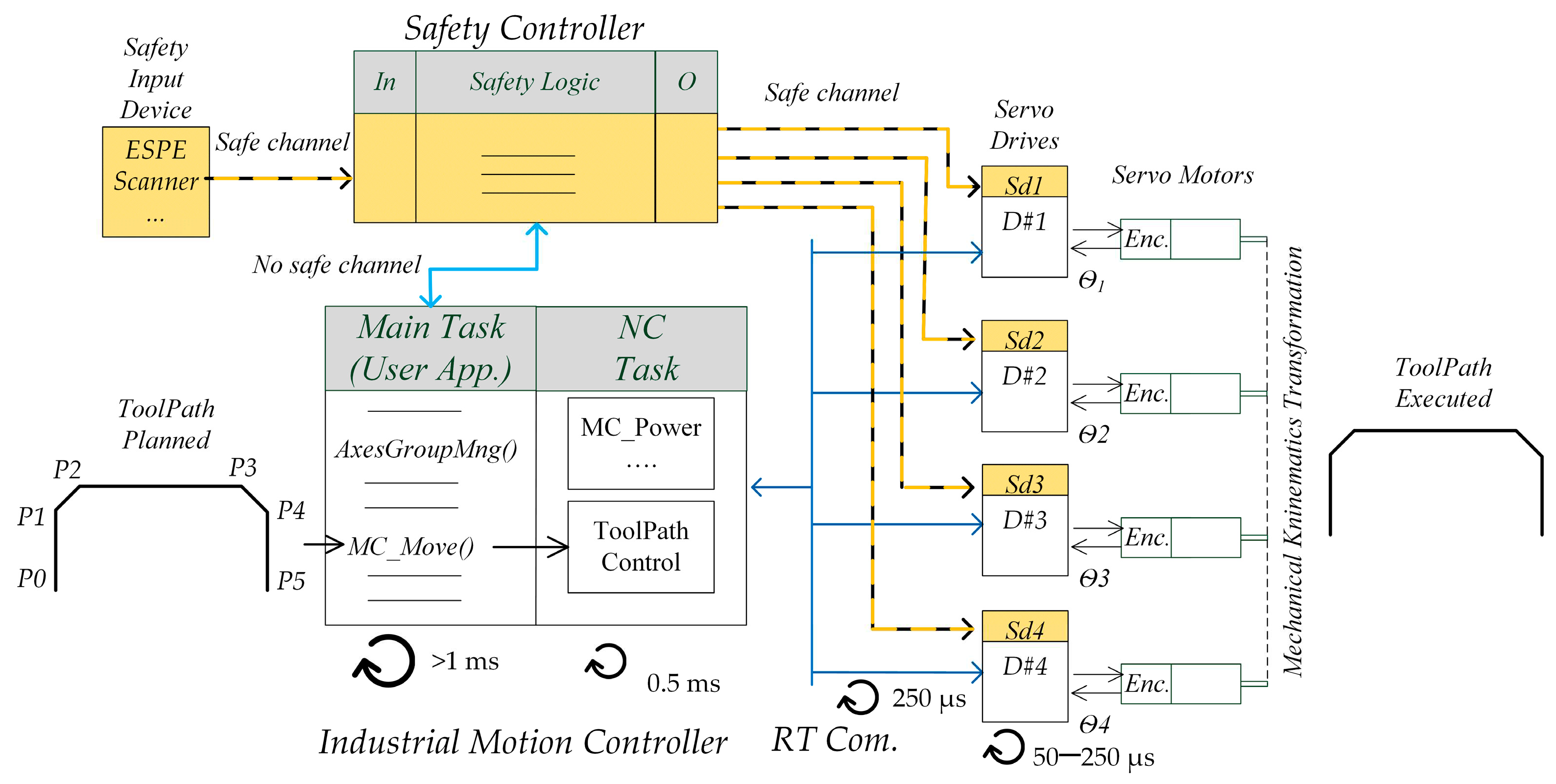
Figure 2.
Example of CDPR configurations: (a) 8-cables fully-constrained (position cannot change without changing the length of the cables); (b) Photo of the developed 4-cables suspended (position can be different even subject to the same cable lengths).
Figure 2.
Example of CDPR configurations: (a) 8-cables fully-constrained (position cannot change without changing the length of the cables); (b) Photo of the developed 4-cables suspended (position can be different even subject to the same cable lengths).
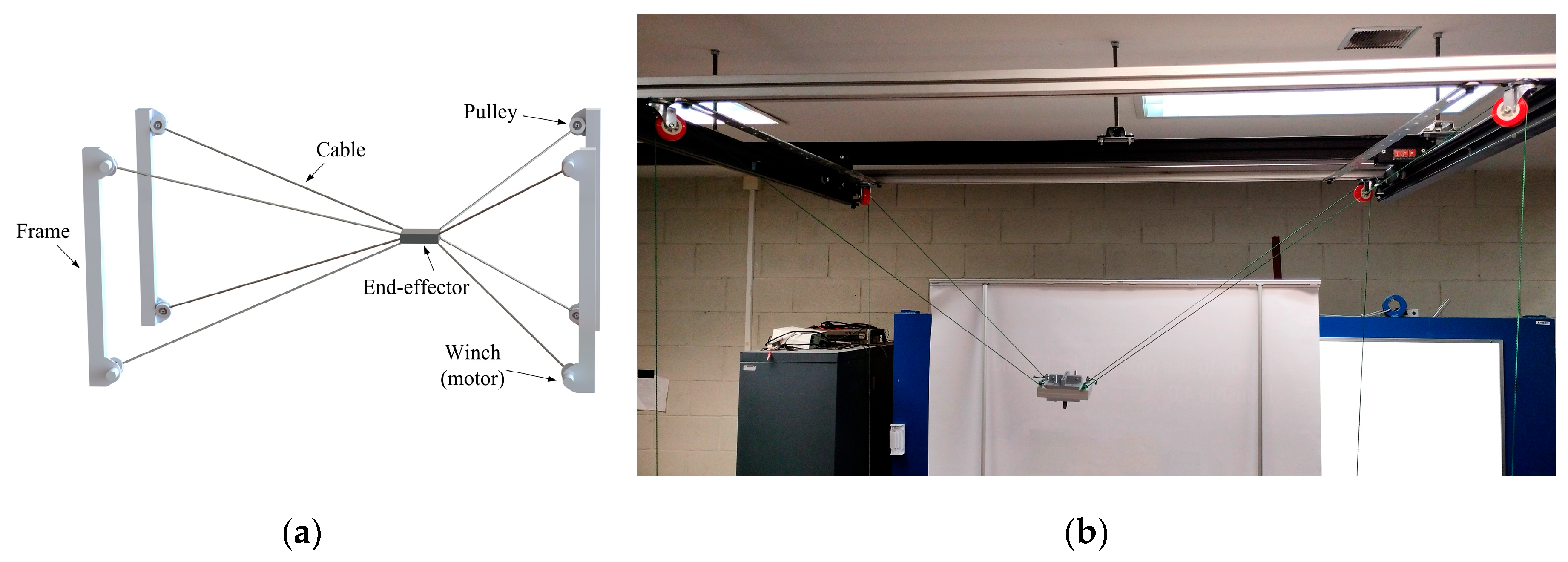
Figure 3.
Safe motion monitoring functionalities examples: (a) STO; (b) SLS with activation of the speed limit; (c) SLS with activation and speed limit exceedance.
Figure 3.
Safe motion monitoring functionalities examples: (a) STO; (b) SLS with activation of the speed limit; (c) SLS with activation and speed limit exceedance.
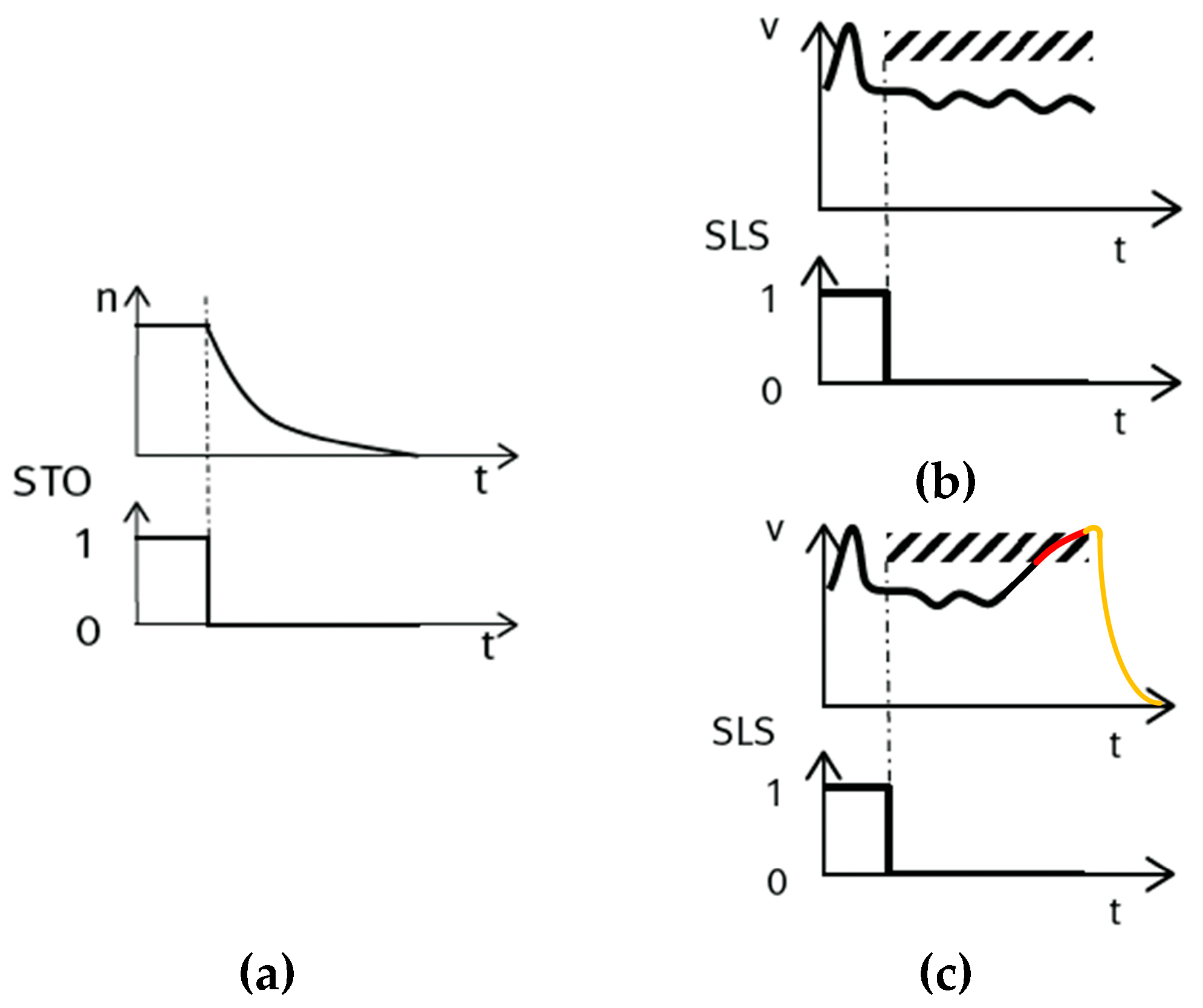
Figure 4.
Sequence process control for executing toolpaths in a suspended 4-cable CDPR configuration in TwinCAT 3 with legacy Beckhoff resources.
Figure 4.
Sequence process control for executing toolpaths in a suspended 4-cable CDPR configuration in TwinCAT 3 with legacy Beckhoff resources.
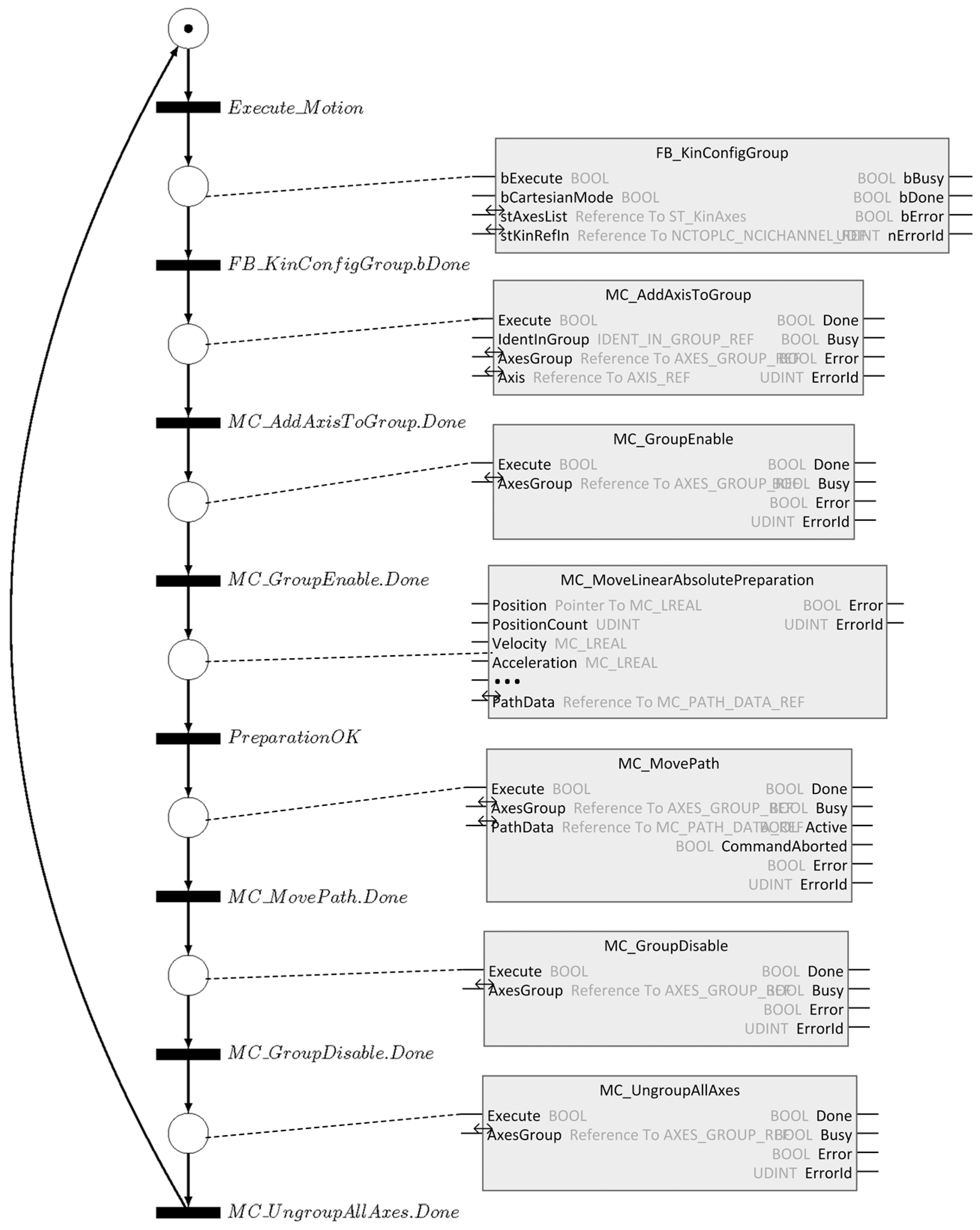
Figure 5.
Proposed reference architecture for the experiment.
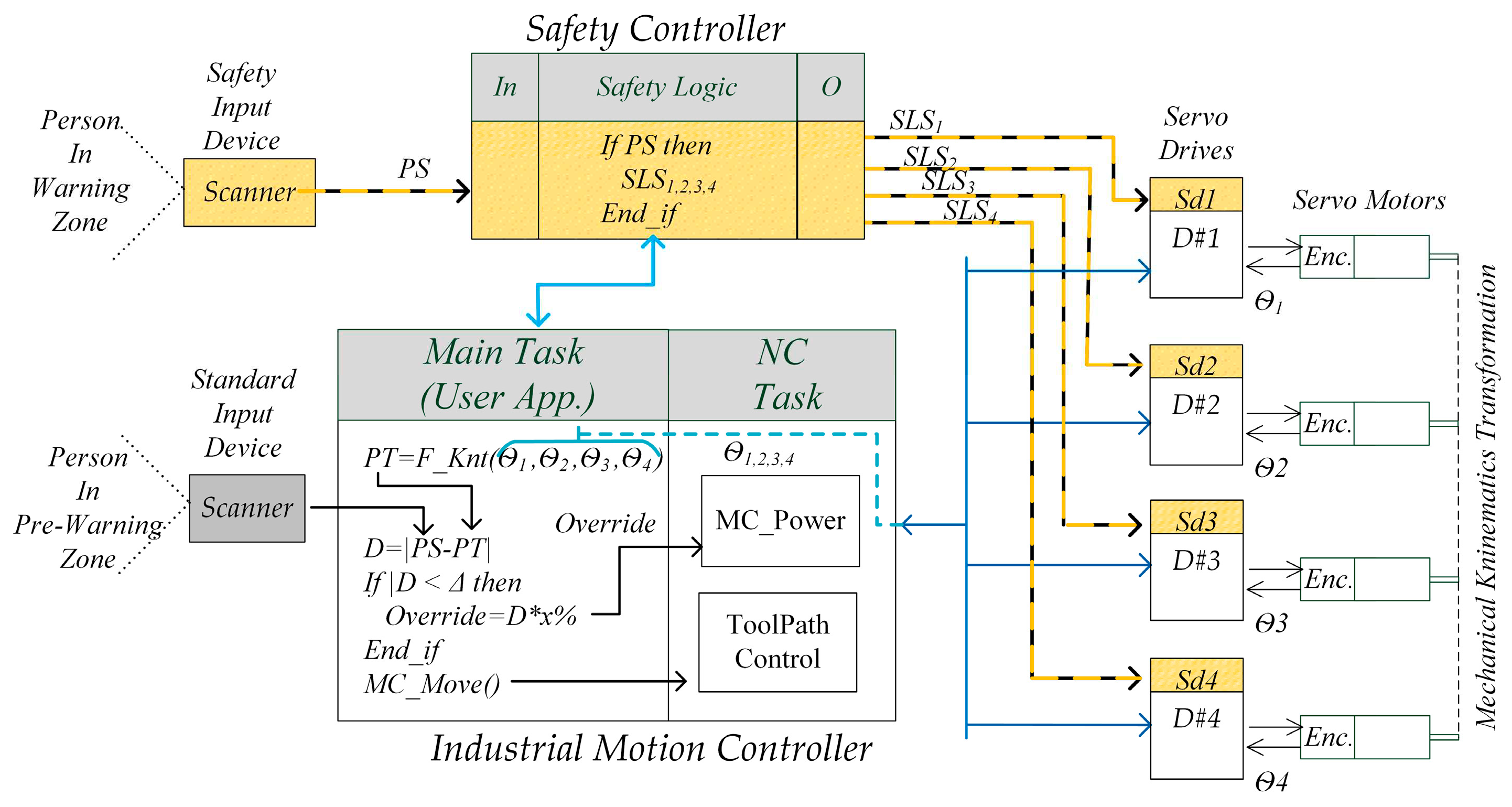
Figure 6.
Zones definitions for a Collaborative CDPR prototype implementation.
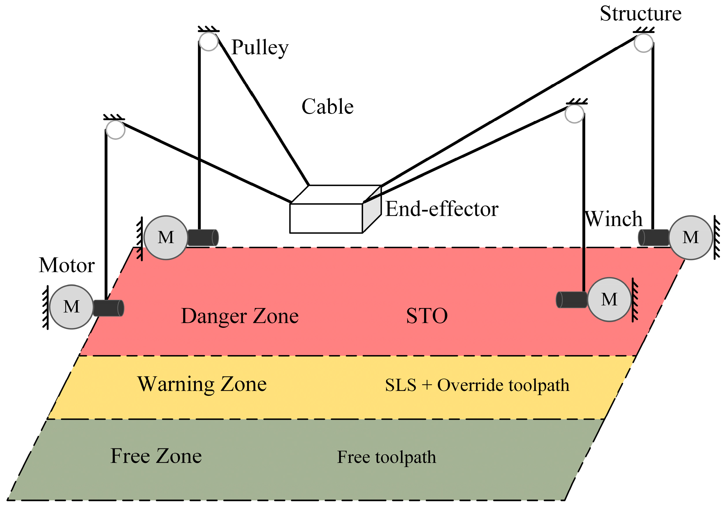
Figure 7.
Result of performing the trajectory under normal conditions (with the operator standing in the “Free Zone”): (a) Time series of the velocity on each axis (cable); (b) 3D view of the toolpath.
Figure 7.
Result of performing the trajectory under normal conditions (with the operator standing in the “Free Zone”): (a) Time series of the velocity on each axis (cable); (b) 3D view of the toolpath.
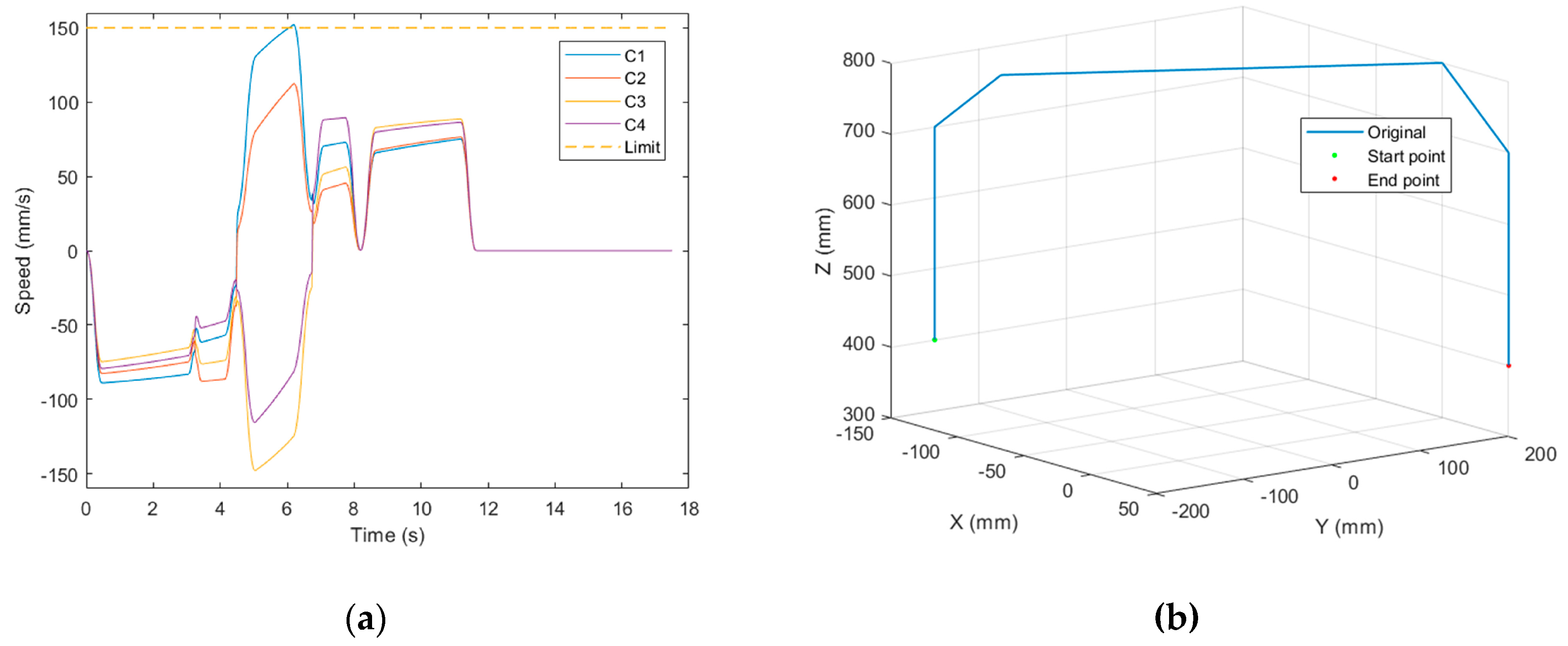
Figure 8.
Result of performing the trajectory when a person entered the Warning Zone, triggering the activation of the SLS safety function and a speed override of the axes group. The vertical red line (“T1”) indicates when an operator entered the Warning Zone. (a) Time evolution of the speed on each axis (cable); (b) Time series of the discrete speed override (level 50%); (c) 3D view of the toolpath.
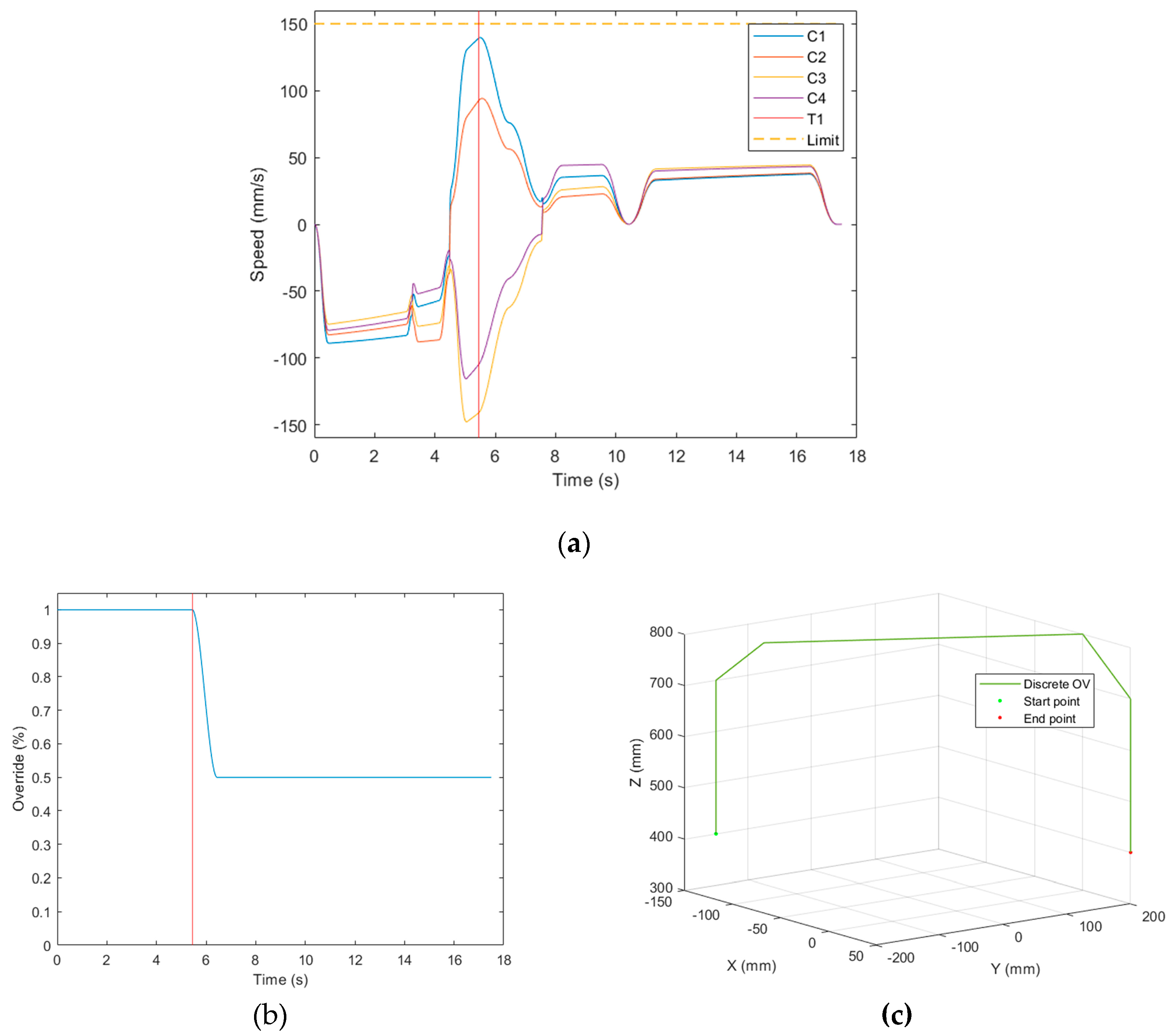
Figure 9.
Result of performing the trajectory when a person entered the warning zone, triggering the activation of the SLS safety function and a speed override of the axes group, but one axis exceeded the safe speed limit value. The vertical blue line (“T1”) indicates when an operator entered the warning zone and the red one (“T2”) represents the time when cable 1 exceeded the safe speed limit: (a) Time evolution of the speed on each axis (cable); (b) Time series of the discrete speed override; (c) 3D view of the toolpath.
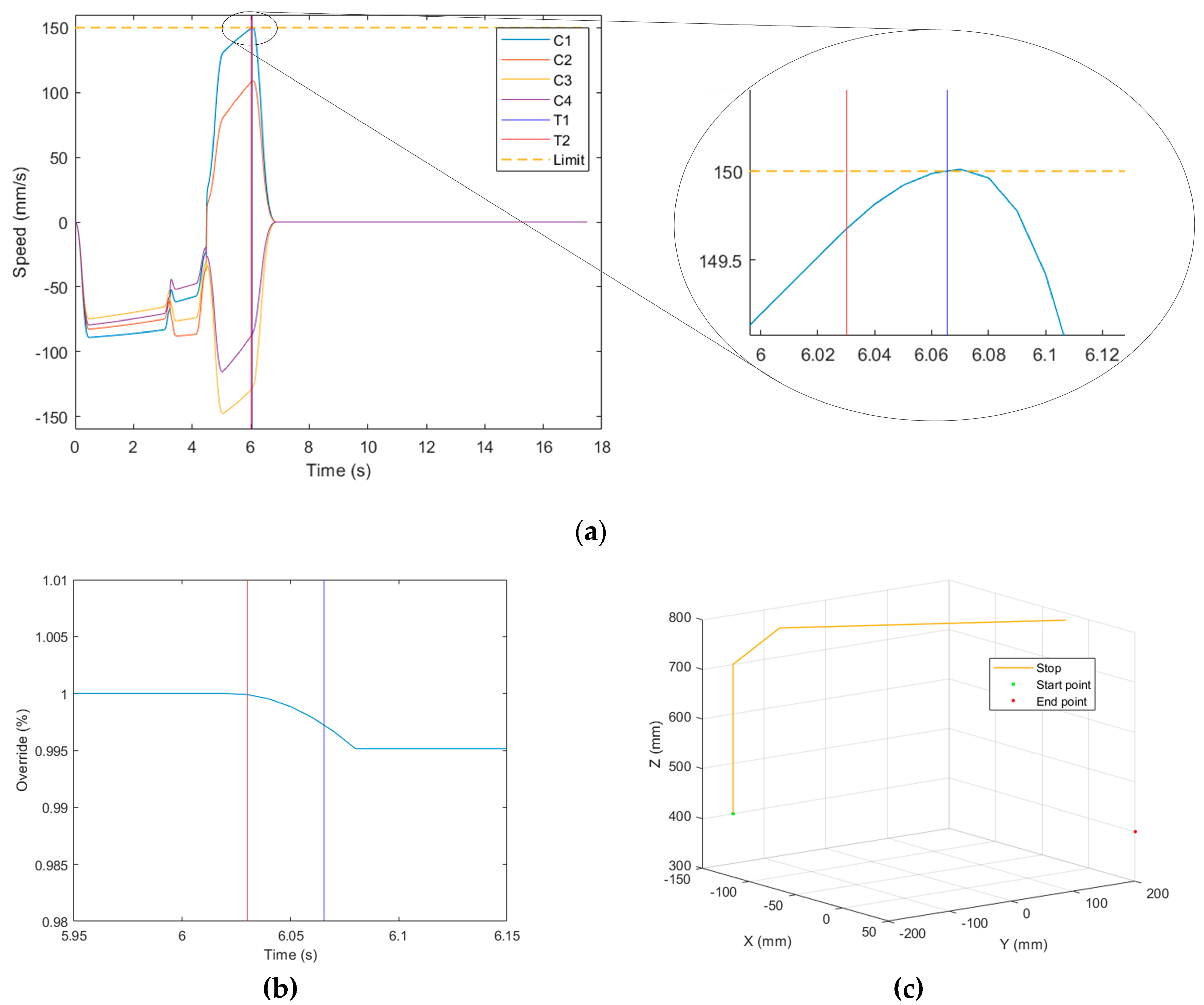
Figure 10.
Proposed zones for a Collaborative CDPR prototype implementation.
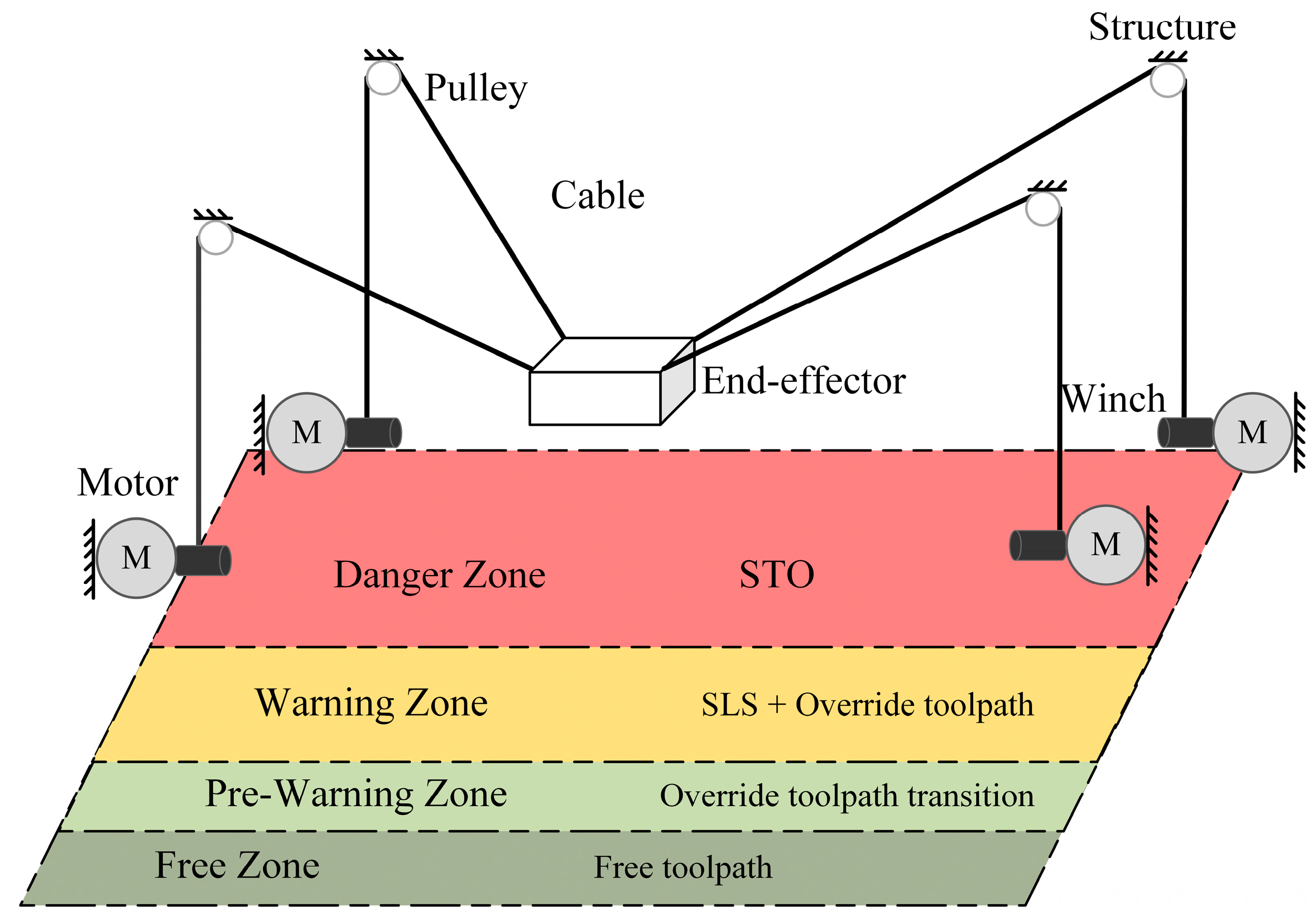
Figure 11.
Result of performing the trajectory when a moving person entered the pre-warning zone and subsequently the warning zone, causing the activation of the SLS safety function. The red vertical line (“T1”) indicates when this person entered the pre-warning zone and the blue vertical line (“T2”) indicates entering the warning zone: (a) Time evolution of the speed on each axis (cable); (b) Time series of the progressive speed override; (c) 3D view of the trajectory.
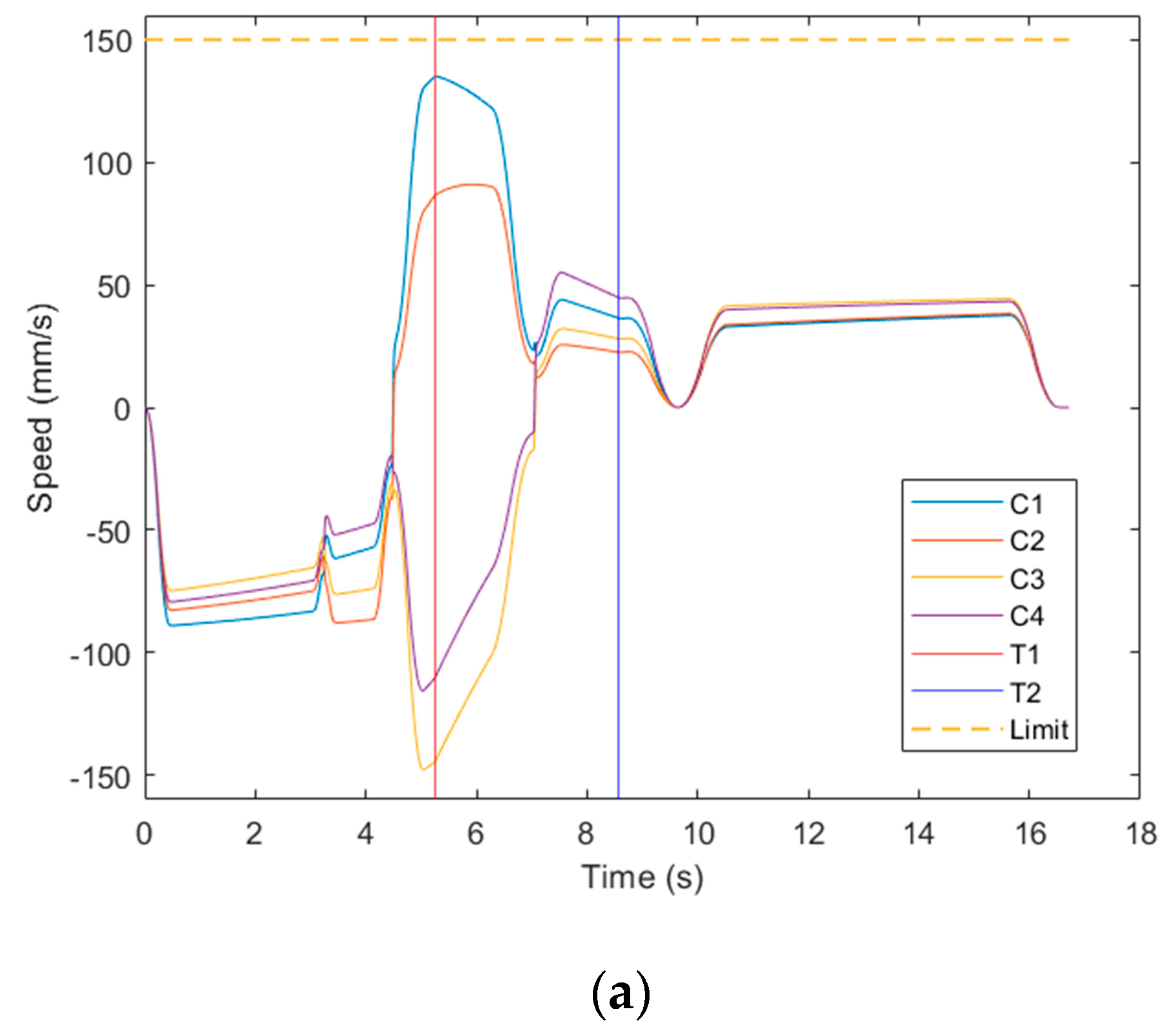
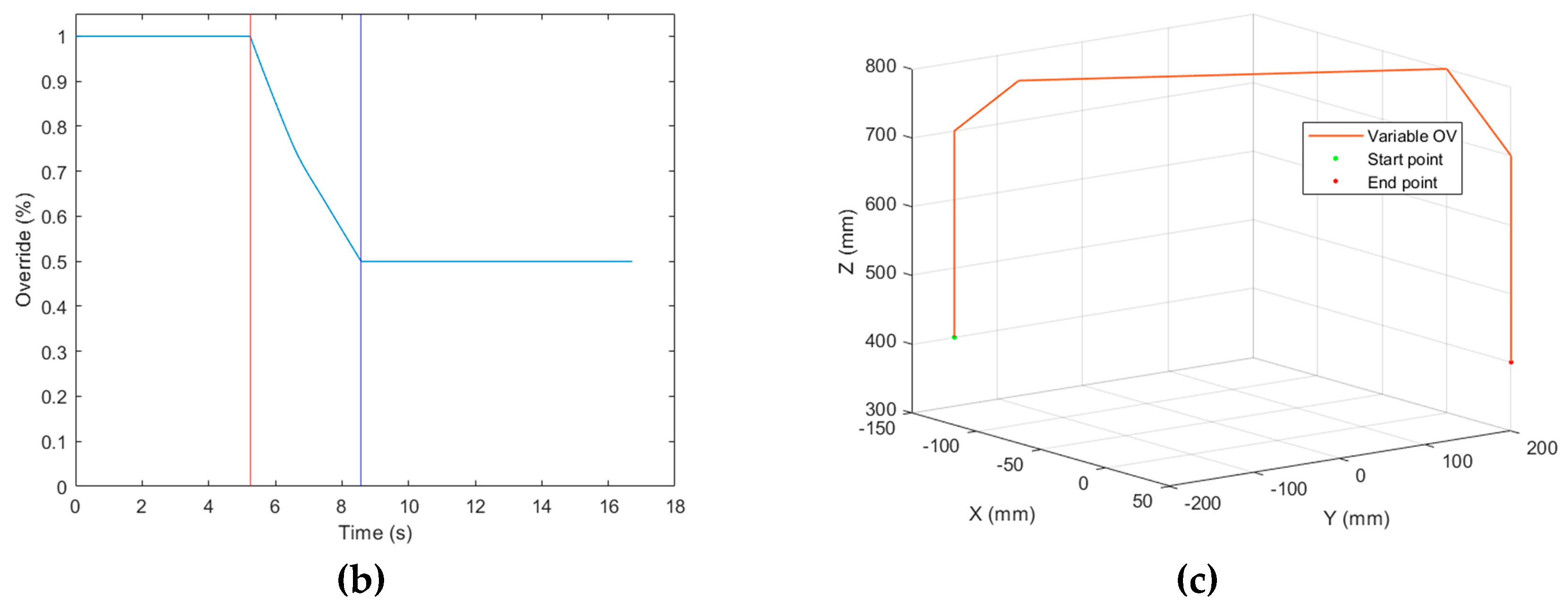

Table 1.
Waypoints of the trajectory.
| N | X (mm) | Y (mm) | Z (mm) | Velocity (mm/s) |
|---|---|---|---|---|
| 1 | -150 | -150 | 400 | - |
| 2 | -150 | -150 | 700 | 100 |
| 3 | -100 | -150 | 800 | 100 |
| 4 | 0 | 200 | 800 | 200 |
| 5 | 50 | 200 | 700 | 100 |
| 6 | 50 | 200 | 400 | 100 |
Disclaimer/Publisher’s Note: The statements, opinions and data contained in all publications are solely those of the individual author(s) and contributor(s) and not of MDPI and/or the editor(s). MDPI and/or the editor(s) disclaim responsibility for any injury to people or property resulting from any ideas, methods, instructions or products referred to in the content. |
© 2024 by the authors. Licensee MDPI, Basel, Switzerland. This article is an open access article distributed under the terms and conditions of the Creative Commons Attribution (CC BY) license (http://creativecommons.org/licenses/by/4.0/).
Copyright: This open access article is published under a Creative Commons CC BY 4.0 license, which permit the free download, distribution, and reuse, provided that the author and preprint are cited in any reuse.


