
Submitted:
18 December 2023
Posted:
19 December 2023
You are already at the latest version
Abstract
Aqueous Zinc ion batteries (ZIBs) possess significant potential in large energy storage systems due to their cost-effectiveness and environmental protection. However, the limited voltage window and poor reaction kinetics of the cathode material are still bottlenecks, restricting the further development of ZIBs. In this work, we rationally design Ni-doped V2O5@3D Ni core/shell composite on carbon cloth electrode (Ni-V2O5@3D Ni@CC) by growing Ni-V2O5 on the free-standing 3D Ni metal nanonets for high-voltage and high-capacity ZIBs. Impressively, the embedded Ni doping increases the interlayer spacing of V2O5, extending the working voltage and improving the Zn2+ kinetics reaction of the cathode materials, at the same time the 3D structure with high specific surface area and superior electronic conductivity benefits to fast Zn2+ transport. Consequently, the as-designed Ni-V2O5@3D Ni@CC cathodes can operate within a wide voltage window from 0.3 to 1.8 V vs. Zn/Zn2+ and deliver a high capacity of 270 mAh g-1 at a high current density of 0.8 A g-1. In addition, the reversible Zn2+ (de)-incorporation reaction mechanisms in the Ni-V2O5@3D Ni@CC cathodes are investigated by multiple characterization methods. As a result, we achieve a big step toward the practical applications of commercial ZIBs.
Keywords:
ZIBs
; Ni-V2O5
; 3D Ni nanonets
; Voltage window
; Reaction kinetics
1. Introduction
Fossil fuels such as coal and oil play a crucial role in human activities. But the rapid reduction of these energy reserves and the environmental damage caused by their usage lead to an urgent energy revolution.[1] As a result, fossil fuels are gradually being replaced by clean energy in the application form of electricity. In the research field of electric energy storage systems, lithium-ion batteries (LIBs) have been developed for over 30 years, received in-depth research and achieved great success in commercial applications.[2] However, energy density limitation, high cost and environmental issues limit the further applications of LIBs.[3] To overcome these issues, researchers are exploring the feasibility of other active metals in energy storage devices to replace LIBs in the future.[4,5,6]
Among all the candidates, aqueous zinc-ion batteries (ZIBs) have received increasing attention as a promising candidate for large-scale energy storage devices due to the apparent advantages of using metallic Zn as the anode[7], including high theoretical capacity (5855 mAh cm-3)[8], low redox potential (-0.76 V vs standard hydrogen electrode, SHE)[9] and low-cost benefit from its vast reserve (the cost of Zn (0.5-1.5 $/lb) is much smaller than that of Li (8-11 $/lb)).[10] However, finding suitable cathode materials for high-performance ZIBs has become a top priority. Currently, manganese-, vanadium- and Prussian blue analogues (PBA)-based cathodes have been proven to be the typical cathode materials for ZIBs.[11] Among them, the manganese-[12,13,14,15,16] and PBA-based materials[17] have ideal charging and discharging platforms[18,19] but usually suffer from insufficient long-term cycling ability[20] and low reversible capacity[21,22,23] because of their intrinsic unstable structure characteristics.[24,25,26,27,28] Therefore, vanadium-based materials with high theoretical specific capacity and adjustable ion-transfer channels will most likely become promising candidates for high-performance cathodes in ZIBs.[29]
Generally, the narrow interlayer spacing[30] and poor electronic conductivity[31] of vanadium-based materials can lead to slow reaction kinetics and unstable structures during Zn2+ (de)-incorporation process, limiting their applications in ZIBs.[32] For this issue, the incorporation of metal ions, such as Na+, Li+, Mg2+, Mn2+, Cu2+, etc.,[33,34,35,36,37] has been classified as one of the most effective strategies to enlarge interlayer spacing. Besides, metallic element incorporation adjusts the composition of V-based materials while changing their structures, and thus improves the electronic conductivity.[38,39,40] Therefore, this incorporation strategy significantly improves the materials’ reaction kinetics from fastening both ion transportation and electron transportation. However, the insertion of metal ions may reduce the theoretical capacity of vanadium-based materials, especially during long-term cycle performance, due to the irreversible structure destruction, leading to a reduction of vanadium ion-storage.[41] Therefore, the influence of the type and the amount of pre-embedded metal ions should be considered when introducing metal ions into vanadium-based materials.[42] In addition, most reported cathode materials are in powder form. In order to be applied as cathodes, the powder must be stacked and bonded on a current collector, which not only blocks the active sites but also increase the “dead mass”, decreasing the energy density of ZIBs and causing an inevitable waste. In this regard, loading electrode active materials on 3D frameworks has been proven to be an effective strategy to avoid the use of adhesives and accumulation of active materials due to their large specific surface area and high porosity. Developing a solution to address both of these crucial problems simultaneously is highly effective yet challenging.
Herein, we propose a rational design of Ni-doped V2O5@3D Ni core/shell composites on carbon cloth (Ni-V2O5@3D Ni@CC) for high-performance ZIBs. Specifically, 3D metallic Ni nanonets were grown on the surface of carbon cloth (CC). Compared with CC, Ni nanonets can be applied as a 3D framework to provide high electronic conductivity and larger surface area, for achieving higher quantity and full usage of active-material-loading. Besides, during the one-step-V2O5 loading process, metallic Ni particles were released from 3D nanonets and incorporated into V2O5, modifying the interlayer structure of the active materials. As a result of this innovation, the as-obtained Ni-V2O5@3D Ni@CC electrode can work in a wide voltage window[43] of 0.3 to 1.8 V versus Zn/Zn2+ and deliver a high capacity of 270 mAh g-1 (~ 1050 mAh cm-3) at a current density of 0.8 mA g-1. Moreover, multiple characterization methods are applied to investigate the reversible Zn2+ (de)-incorporation reaction mechanism. Our strategy aims to broaden the application range to other materials and drive the practical commercial usage of ZIBs.
2. Experimental Section
Chemicals. Carbon cloth (1 cm × 2 cm), hexamethylenetetramine (HMT, C6H12N4, 99%, Sinopharm Chemical Reagent Company Limited), nickel chloride hexahydrate (NiCl2·6H2O, 99%, Sigma-Aldrich), hydrogen peroxide solution (H2O2, 30%, Jnan Mama Technology Company Limited ), zinc sulfate (ZnSO4·7H2O, 99.5%, Sinopharm Chemical Reagent Company Limited), vanadium pentoxide (V2O5, Xiya Reagent) were used directly without any further purification.
Fabrication of Ni(OH)2@CC. Firstly, the purchased CC was soaked in 5 M HCl aqueous solution to experience a complete cleaning, then washed in deionized (DI) water and pure ethanol, each for 15 min, in turn, to remove extra HCl. After that, CC was dried in air. Then the clean CC was cut into 1 cm × 2 cm pieces then used as a substrate to deposit Ni(OH)2 on its surface. Clean CC was protected by ethoxylate except for an exposed area of 1 cm2 on both sides. The Ni precursor solution was obtained by adding 0.125 mol NiCl2·6H2O and 0.25 mol HMT into 1 L DI water and experiencing a complete mixing. The CC substrate with an exposed area of 1 cm2 mentioned before was immersed in 30 mL Ni precursor solution in a 50 mL glass beaker. The beaker was heated in an electric oven at 100 °C for 8 h to synthesize Ni(OH)2 on CC. During this process, light green products are generally grown on the surface of CC. Finally, after being completely rinsed with distilled water and pure ethanol in turn for several times and dried in a vacuum oven for over 12 h, the Ni(OH)2@CC samples were successfully fabricated.
Preparation of 3D Ni@CC. To obtain 3D Ni@CC, the fabricated Ni(OH)2@CC samples were put into a porcelain boat, and then heated under an Ar/H2 mixed atmosphere ( the volume percent of H2 is 5%) at 400 °C for 1 h. The temperature rising rate was set to 5 °C min-1. During this process, Ni(OH)2 was transferred into Ni. The 3D Ni@CC samples were obtained after being cooled to room temperature.
Preparation of Ni-V2O5@3D Ni@CC. The Ni-V2O5@3D Ni@CC electrode was prepared by a simple hydrothermal synthesis method. 0.91 g of divanadium pentaoxide was added into 40 mL of hydrogen peroxide solution. Subsequently, the above solution and 3D Ni@CC were transferred into a 100 mL Teflon-lined stainless-steel autoclave. After being sealed, these materials were heated under 180 °C and kept for 24 h. After cooling to room temperature, the autoclave was taken out, and the obtained samples were fully cleaned by ethanol, and then put into an oven to dry overnight at 80 °C. Then, the samples were annealed in air at 300 °C for 1 h at a heating rate of 2 °C min-1 to get Ni-V2O5@3D Ni@CC. The mass loading of Ni-V2O5 is about 2.0 mg cm-2.
Electrochemical measurements. All electrochemical performances of the samples were measured by a CHI 660C electrochemical workstation (CH Instruments Inc.). The Ni-V2O5@3D Ni@CC cathode performance in full-cell tests was investigated in the CR2025 coin cells. We chose glass microfiber (Whatman) as the separator and bare Zn foil (being washed by ethanol) as anode material. 2 M ZnSO4 electrolyte was obtained by dissolving enough zinc sulfate into DI water. The assembling and testing process of coin cells were all experienced in an open atmosphere at a room temperature.
Characterization. Quanta 400 FEG scanning electron microscope (SEM) and a Tecnai G2 F20 S-Twin transmission electron microscope (TEM) were used to characterize microstructures of these samples. SEM was operated from 5.0-20.0 kV, and TEM was conducted at an accelerating voltage of 200 kV. The crystal structures of the samples were analyzed by X-ray diffraction (XRD) with a Bruker D8 diffractometer. The results of X-ray photoelectron spectroscopy (XPS) characterization were shown by an Axis Ultra DLD X-ray photoelectron spectroscopy and all data were referenced to the C 1s = 284.8 eV.
3. Results and Discussion
The preparation process of the Ni-V2O5@3D Ni@CC electrode is illustrated in Figure 1a (the details can also be found in the experiment section) while scanning electron microscope (SEM) images during different steps can be seen in Figure 1b-g. CC has excellent characteristics including high electrical conductivity, remarkable structural flexibility and robust mechanical strength, which allows for its direct use as the current collector during this work. Besides, metal oxides/hydroxides can be easily grown on CC, therefore avoiding an extra usage of binder in the electrode fabrication process.[44] But CC still have an intrinsic shortage, which is the small surface area resulting in a low mass loading of active materials.[45] Therefore, to conquer this shortage, in the first step, Ni(OH)2 nanosheets were grown on the CC surface. The SEM images of Ni(OH)2@CC can be seen in Figure 2b-c, where the nanosheets were vertically grown on bare CC through immersion in the solution and experiencing the reaction between HMT and NiCl2·6H2O. We can see from the enlarged image that the large number of flexible Ni(OH)2 nanosheets proved a much larger surface area in comparison with CC. Then the 3D metallic Ni nanonets (Figure 1a) were derived from the Ni(OH)2 nanosheets by a reduction treatment under H2 atmosphere. It can be seen that the obtained 3D metallic Ni nanonets still maintain a large surface area, and the morphology of Ni(OH)2 transformed from nanosheets to well-dispersed and rob-shaped 3D nanosheets, offered a more sufficient space for active materials to load (Figure 1d-e). This 3D Ni@CC can serve as well as electrically conductive and stable supports for active materials, which is V2O5 in this research. Besides, Ni can act as incorporation ion to intercalate active material, changing internal structure, facilitating ion and electron transportation, making the oxidation-reduction reaction occur quickly. As for the Ni-pollution problem, it mainly refers to the environmental damage caused by the Ni metal smelting process. But in this research, raw material for synthesis Ni metal is environmentally friendly Ni(OH)2, which is usually the product obtained from alkaline treatment of industrial wastewater containing Ni. Afterwards, nickel exists in its elemental form in the cathode of ZIBs, which is stable and easy to recycle, greatly reducing its bad impact on the environment.[46]
Then, after a simple hydrothermal synthesis method, V2O5 was grown on the surface of 3D Ni nanonets. The addition ratios of raw materials have experienced tests from low to high, to obtain the most suitable ratio between 3D Ni nanonets and Ni-V2O5, to maximize the usage of surface area, for a better electrochemical result. For example, the additive amount of NiCl2·6H2O was changed from 0.100 mol to 0.200 mol. As the amount continue increase, the final performance didn’t improve and even deteriorated. We believe that this can be attributed to the continued growth of Ni(OH)2, which finally led to heavier 3D Ni nanonets with smaller specific surface area, and easier to break down during the V2O5 loading process, which is a damage to the electrochemical performance of cathodes. And finally, we concluded that the ideal additive amount of NiCl2·6H2O is 0.125 mol.
The SEM image of as-synthesized Ni-V2O5@3D Ni@CC demonstrates that V2O5 nanosheets were anchored homogeneously on the surface of the 3D Ni nanonets to form unique core-shell composites (Figure 1f-g). It should be noticed that during the V2O5 loading process, Ni atoms were released from Ni nanonets, achieving an incorporation to the interlayered V2O5. The Ni-V2O5@3D Ni@CC results in a higher energy density and transfer rate of ZIBs electrode while maintaining a high stability. More in-depth characterization of this part will be shown later.
We carried out a high-angle annular dark-field (HAADF)-scanning transmission electron microscopy (STEM) to further investigate the nanostructures of Ni(OH)2@CC, 3D Ni@CC and Ni-V2O5@3D Ni@CC samples (Figure 2a-c). From Figure 2a, we can see that abundant flexible Ni(OH)2 nanosheets were well synthesized on CC. After a reduction process, the Ni(OH)2 nanosheets were transferred into 3D metal Ni nanonets on the surface of CC, with a loose rod-shaped structure (Figure 2b). Finally, Ni-V2O5 nanosheets were grown on the Ni nanonets through a hydrothermal process. Through a higher resolution STEM image and elements characterization of Ni-V2O5@3D Ni@CC (Figure 2c-d), not only robust V2O5 can be seen, but the incorporation of Ni element can be proved as well. There is an element distribution characterization of the sample in Figure 2d, in which bright parts represent areas with physical objects of Ni-V2O5 nanosheet. We selected a very small area from Figure 2d by using a red dashed box, called spectrum image to analyze its construction. The green pixels represent the V element, and the blue pixels represent the Ni element. It can be easily understood that due to the large mass loading of V2O5 fully covered 3D Ni nanonets, the V element is uniformly distributed on the sample, which reflected on the image are uniformly distributed green pixels. Blue pixels are also uniformly distributed on the image instead of concentrating on the area of Ni nanonets, representing Ni achieved a good in-corporation with V2O5 and a uniform distribution in it. In addition, electron energy loss spectroscopy (EELS) results from this area further demonstrate the occurrence of V2O5 growth and Ni incorporation (Figure 2e). EELS utilizes an incident electron beam to undergo inelastic scattering in the sample, and the energy loss of electrons directly reflects the mechanism of scattering, the chemical composition of the sample, and the thickness information. Therefore, it can analyze the elemental composition and other information from the analyzing area. Blue vertical lines in Figure 2e displayed different energy-loss caused by different elements, where two characteristic peaks belonging to V and Ni elements were detected, which is coordinated to the result from Figure 2d.
Apart from SEM and TEM images, our research also characterized the components and structures of samples through X-ray diffraction (XRD) and X-ray photoelectron spectroscopy (XPS). As shown in Figure 3a and S1, XRD patterns of different samples can be indexed well to the Ni(OH)2 (#38-0715), metallic Ni (#04-0850) and V2O5 (#77-2418), indicating that all these samples are well fabricated as expected. According to the XRD standard card of V2O5 (#77-2418), we choose three characteristic peaks (20.3°, 31.1°, 34.3°) to give an accurate description of the peaks shifting. In comparison with those characteristic peaks of pure V2O5@CC sample (20.3°, 31.1°, 34.3°), the corresponding peaks of Ni-V2O5@3D Ni@CC (19.8°, 30.7°, 34.0°) shift towards lower degrees, according to the Bragg equation: 2d sinθ = λ (d represents the distance between adjacent crystal layer, θ represents the angle between the incident X-ray and the crystal plane, λ It is the wavelength of X-ray), if the characteristic peak shifts towards a small angle while λ remains constant, d will be enlarged, representing a bigger interlayer space. It can be calculated through Bragg equation that the d-spaces have been enlarged for about 0.5 Å. This evidence strongly proves that the interlayer spacing of the samples is enlarged due to the incorporation of Ni ion. In addition, the high-resolution XPS spectra of Ni element from 3D Ni@CC and Ni-V2O5@3D Ni@CC were also presented in Figure 3b, further demonstrating the process of Ni ion incorporation. Clearly, in comparison with 3D Ni@CC sample, the Ni0 of Ni element in the metallic nanonets sample disappeared and the main valence state became Ni2+ in Ni-V2O5@3D Ni@CC (Figure 3b). Besides, according to the XPS spectra for V2O5 only vs. Ni incorporated V2O5, there are shifts in the peak energies for vanadium and oxygen elements (Figure S2). Since Ni is incorporated within the interlayer spacing, it can be deduced that the intercalation of Ni not only changed the inner structure, but also affect the electronic environment of V and O, causing shifts in the binding energies. All these evidences indicated the occurrence of Ni incorporation, which is well consistent with the results from energy-dispersive spectroscopy (EDS) elemental mappings of SEM (Figure S3-4). It can be speculated that during the hydrothermal process for V2O5 loading, Ni0 was released from Ni nanonets and transferred into Ni2+, to incorporate with V2O5, intercalating into its layered structure to achieve Ni-V2O5 and then grown on 3D nanonets. Therefore, the 3D Ni nanonets could not only serve as the framework for the better growth of V2O5 nanosheets but also participate in adjusting V2O5 layered structure. In other words, both the active site and spacing were enhanced for the diffusion of Zn2+ through such a facile one-step strategy.
The ZIBs were assembled by using metallic Zn as the anode to couple with Ni-V2O5@3D Ni@CC cathode or V2O5@CC cathode (denoted as Ni-V2O5@3D Ni@CC-based ZIB or V2O5@CC-based ZIB) and 2 M ZnSO4 as an electrolyte. The corresponding electrochemical properties were also analyzed. The performance in oxygen evolution reaction (OER) activity is an important parameter for describing cathode stability in ZIBs. Higher reaction potential means the electrode material has a better stability during cycle performance. Meanwhile, a cathode material with higher OER potential can provide a wider voltage window for ZIBs, to realize a better performance closer to commercial usage. As it can be seen from Figure S5, during charging, there is a higher potential (~ 1.9 V) required for the Ni-V2O5@3D Ni@CC electrode to start decomposition and release oxygen, as the current density begins to increase rapidly. While V2O5@CC only allows for a lower potential at about 1.6 V.
Then we carried out cyclic voltammetry (CV) curves at the scan rate of 1.0 mV s-1. By comparing with pure V2O5@CC-based ZIB (0.3-1.5 V), the Ni-V2O5@3D Ni@CC-based ZIB realizes a wider working potential window of 0.3-1.8 V, this can be attributed to the Ni-V2O5@3D Ni@CC electrode with a lower OER activity, as we have mentioned before. The wider voltage window enables the ZIBs to work at high energy density (Figure 4a, S6). In addition, we also note that this working potential window is larger than that of other recently reported V2O5-based cathodes (e.g., Zn0.25V2O5, Ca0.25V2O5 and Na0.33V2O5).[7,36,47,48]
Then, the galvanostatic charge-discharge (GCD) curves of V2O5@CC-base ZIB and Ni-V2O5@3D Ni@CC-based ZIB under a current density of 0.8 A g-1 were carried out to compare the specific capacity (Figure 4b). Obviously, the Ni-V2O5@3D Ni@CC electrode delivers a much higher capacity than that of V2O5@CC. Besides, as for the Ni-V2O5@3D Ni@CC electrode, there’s an obvious charge/discharge platform at about 1.2 V, which is obviously higher than that of the V2O5@CC cathode. This is another powerful evidence to prove that the improved cathode material is more suitable for practical usage not only because of its high energy density and stability but also because of its wider working voltage window and higher working voltage platform, which is all better than that of V2O5@CC electrode. Figure 4d shows the GCD curves of Ni-V2O5@3D Ni@CC under various current densities (from 0.4 to 4.8 A g-1), from which obvious charge and discharge plateaus can be discerned, consistent with the CV result (Figure 4c). During these two tests, it can be observed that the working voltage platform is still maintained steadily ignoring the various changes of current density, proving that the Ni-V2O5@3D Ni@CC electrode is an ideal cathode material for ZIBs usage in different circumstances. It should be noticed that even though the voltage window seems to get smaller as the current density increases, this can be explained that the difference in CV curves is caused by capacity. The capacity of cathode materials always decreases under a faster voltage scan rate, since Zn ions can’t be (de)intercalated completely. Therefore, the CV curve area is getting small, while the voltage window is remaining still actually.
In the rate performance tests, the Ni-V2O5@3D Ni@CC-based ZIB presents average discharge capacities of 330, 270, 216, 166, 152, and 140 mAh g-1 at current densities of 0.4, 0.8, 1.6, 3.2, 4.0, and 4.8 A g-1, respectively. Moreover, when the current density returns back to 0.8 A g-1, the discharge capacity recovers to 270 mAh g-1 (~1050 mAh cm-3), suggesting an excellent capability of rate performance. Meanwhile, the Ni-V2O5@3D Ni@CC all exhibits a high Coulombic efficiency (CE) at different current density from 0.4 to 4.8 A g-1, then back to 0.8 A g-1 (Figure 4e). In the long-cycle stability test, even under a high current density of 4.8 A g-1, the Ni-V2O5@3D Ni@CC-based ZIB still maintains a nearly non-decreased 100% CE after cycling over 500 times with a specific capacity of about 110 mAh g-1 (volume specific capacity of about 430 mAh cm-3, showed in Figure 4f). The performance reported here is better than that of other V2O5-based compounds such as V2O5/CC, V2O5/MXene, NH4+-V2O5, V2O5/rGO etc.[5,6,49,50,51,52,53,54] Meanwhile, the smaller resistance of Ni-V2O5@3D Ni@CC-based ZIB in comparison with V2O5@CC-based ZIB proved by electrochemical impedance spectroscopy (EIS) test (can be seen in Figure S8) can well demonstrate that the incorporation of Ni in V2O5 active material not only benefits the energy storage performance and cycle stability but also improves the Zn2+ transport ability inside cathode, giving the Ni-V2O5@3D Ni@CC-based ZIB a better application potential. This can be explained that the incorporation of Ni ions not only enlarged the interlayer space of V2O5, allowing more Zn ions to intercalate, but also broadened Zn2+ ion transport channels, to fasten their moving speed inside electrode active material. Meanwhile, the broadened channels can escape from structure breakage during Zn2+ ion transportation and then improve the stability of the cathode during cycling.
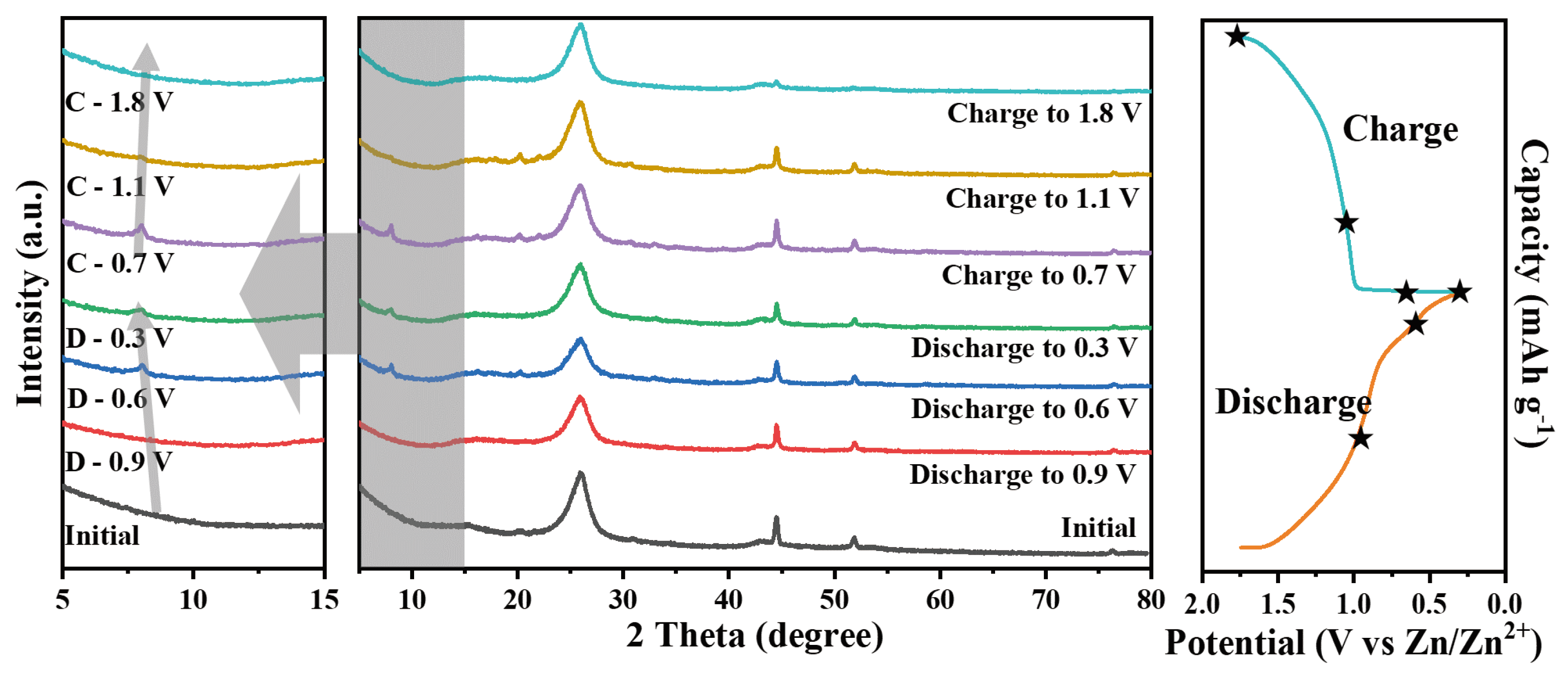
In order to gain more insight into the (de)incorporation process of Zn2+ in the Ni-V2O5@3D Ni@CC-based ZIB, ex-situ XRD analysis was performed. As displayed in Figure 5, during the discharging process, there’s a characteristic peak of the Ni-V2O5@3D Ni@CC electrode appeared on the position of 8.32°, representing an interlayer structure appearance due to the intercalation of Zn2+ ions inside the cathode. The characteristic peak shifted toward a lower angle (8.08° at 0.6 V) as the potential decreased until reaching the fully discharged state (7.92° at 0.3 V). During the charging process afterwards, the characteristic peak shifted back to the higher angles (8.04° at 0.7 V and 8.08° at 1.1 V), then disappeared again just like the beginning after being fully charged to 1.8 V. During the discharge process, Zn2+ ions are gradually intercalated into the cathode, resulting in a contraction of interlayer spacing, which could be further recovered upon voltage reversal. This is strong evidence to prove that the energy storage mechanism of the Ni-V2O5@3D Ni@CC electrode is Zn2+ ions (de)intercalation. Meanwhile, the small shift of characteristic peaks represents a smaller interlayer-structure change during the charge/discharge process due to the existence of Ni ions, leading to a more stable cathode material.
4. Conclusions
In summary, we have designed Ni-doped V2O5@3D Ni core/shell composites on CC as an advanced cathode material for high-performance ZIBs. The 3D Ni nanonets with electronic conductivity composited on CC can provide a high specific surface area for V2O5 loading, which can conquer the inevitable shortage of CC. During the V2O5 loading process through a hydrothermal reaction, Ni atoms are transferred from Ni0 to Ni2+, and subsequently released from Ni nanonets to incorporate with V2O5. The intercalated Ni ions enlarged the interlayer space of the loaded V2O5, which is favourable for Zn2+ intercalation and transportation while maintaining its intrinsic structure. The as-prepared Ni- V2O5@3D Ni@CC electrode delivered a wide voltage window of 0.3 to 1.8 V versus Zn/Zn2+ and presented a high capacity of 270 mAh g-1 at a current density of 0.8 mA g-1. Moreover, even under a higher current density of 4.8 A g-1, the Ni-V2O5@3D Ni@CC-based ZIB still maintains almost 100% CE after cycling over 500 times. Our research provides a new pathway to realize a better performance for V-based cathode materials and makes a big step toward the practical applications of commercial ZIBs. In further research, we can allocate more resources to systematically studying the usage of alternative materials and their impact on battery performance. This will allow us to obtain research results with reduced costs, simplified preparation methods, and increased practical value. The “3D metallic structure & incorporation” strategy can be expected to extend to other metals and electrode active materials, and cooperate with other improvement strategies including electrolyte and anode research areas on ZIBs, which will also favor the further design of high-performance ZIBs.
Supplementary Materials
The following supporting information can be downloaded at the website of this paper posted on Preprints.org, Figure S1: XRD patterns of Ni(OH)2@CC and 3D Ni@CC; www.mdpi.com/xxx/s2 Figure S2: XPS spectra for 3D Ni@CC and Ni-V2O5@3D Ni@CC samples of (a) V and (b) O characteristic peaks; www.mdpi.com/xxx/s3 Figure S3: SEM image and corresponding elemental distribution of Ni-V2O5@3D Ni@CC; www.mdpi.com/xxx/s4 Figure S4: SEM image and corresponding elemental distribution of V2O5@CC; www.mdpi.com/xxx/s5 Figure S5: OER polarization curves of V2O5@CC and Ni-V2O5@3D Ni@CC; www.mdpi.com/xxx/s6 Figure S6. CV curves of V2O5@CC//Zn cell; www.mdpi.com/xxx/s7, Figure S7: EIS Nyquist plots for V2O5@CC//Zn and Ni- V2O5@3D Ni@CC//Zn cells.
Author Contributions
Conceptualization, Y.P. and Z.P.; methodology, T.W., S.Z.; validation, T.W., S.Z., J.C. and R.L.; writing-original draft preparation, S.Z.; writing-review and editing, X.Z., Y.P., Z.P.. All authors have read and agreed to the published version of the manuscript.
Funding
This research received no external funding.
Data Availability Statement
The data used to support the findings of this study are available from the corresponding author upon request.
Acknowledgments
This work was supported by the Fundamental Research Funds for the Central Universities, conducted at Tongji University.
Conflicts of Interest
The authors declare no conflict of interest.
References
- Liu, H.; Wang, J.-G.; You, Z.; Wei, C.; Kang, F.; Wei, B., Rechargeable aqueous zinc-ion batteries: Mechanism, design strategies and future perspectives. Materials Today 2021, 42, 73-98.
- Huang, M.; Wang, X.; Liu, X.; Mai, L., Fast Ionic Storage in Aqueous Rechargeable Batteries: From Fundamentals to Applications. Advanced Materials 2022, 34, (9).
- Yan, J.; Ang, E. H.; Yang, Y.; Zhang, Y.; Ye, M.; Du, W.; Li, C. C. , High-Voltage Zinc-Ion Batteries: Design Strategies and Challenges. Advanced Functional Materials 2021, 31, (22).
- Song, J.; Xu, K.; Liu, N.; Reed, D.; Li, X., Crossroads in the renaissance of rechargeable aqueous zinc batteries. Materials Today 2021, 45, 191-212.
- Gourley, S. W.; Brown, R.; Adams, B. D.; Higgins, D. J. J., Zinc-ion batteries for stationary energy storage. Joule 2023, 7, (7), 1415-1436.
- Yang, X.; Gao, T.; Zhao, R.; Wu, Q.; Shi, K.; She, Z.; Lu, S.; Xie, Q.; Ruan, Y. J. E. T., Expanding Layer Spacing of Carbon-Coated Vanadium Oxide via Ammonium Ions for Fast Electrochemical Kinetics in Aqueous Zinc-Ion Batteries. Energy Technology 2023, 11, (2), 2200990.
- Li, Z.; Tan, J.; Wang, Y.; Gao, C.; Wang, Y.; Ye, M.; Shen, J., Building better aqueous Zn-organic batteries. Energy & Environmental Science 2023, 16, (6), 2398-2431.
- Zhao, Z.; Zhang, H.; Shi, X.; Zhang, Y.; Tang, C.; Zhao, H.; Liu, J.; Wang, G.; Li, L. J. S., Zincophilic Metal-Organic-Framework Interface Mitigating Dendrite Growth for Highly Reversible Zinc Metal Batteries. Small 2023, 2304723.
- Li, M.; Li, Z.; Wang, X.; Meng, J.; Liu, X.; Wu, B.; Han, C.; Mai, L., Comprehensive understanding of the roles of water molecules in aqueous Zn-ion batteries: from electrolytes to electrode materials. Energy & Environmental Science 2021, 14, (7), 3796-3839.
- Dong, H.; Li, J.; Guo, J.; Lai, F.; Zhao, F.; Jiao, Y.; Brett, D. J. L.; Liu, T.; He, G.; Parkin, I. P., Insights on Flexible Zinc-Ion Batteries from Lab Research to Commercialization. Advanced Materials 2021, 33, (20).
- Lin, Z.; Shi, H.-Y.; Lin, L.; Yang, X.; Wu, W.; Sun, X., A high capacity small molecule quinone cathode for rechargeable aqueous zinc-organic batteries. Nature Communications 2021, 12, (1).
- Zhao, J.; Xu, Z.; Zhou, Z.; Xi, S.; Xia, Y.; Zhang, Q.; Huang, L.; Mei, L.; Jiang, Y.; Gao, J.; Zeng, Z.; Tan, C., A Safe Flexible Self-Powered Wristband System by Integrating Defective MnO2–x Nanosheet-Based Zinc-Ion Batteries with Perovskite Solar Cells. ACS Nano 2021, 15, (6), 10597-10608.
- Zhu, X.; Cao, Z.; Wang, W.; Li, H.; Dong, J.; Gao, S.; Xu, D.; Li, L.; Shen, J.; Ye, M., Superior-Performance Aqueous Zinc-Ion Batteries Based on the In Situ Growth of MnO2 Nanosheets on V2CTX MXene. ACS Nano 2021, 15, (2), 2971-2983.
- Cui, G.; Zeng, Y.; Wu, J.; Guo, Y.; Gu, X.; Lou, X. W., Synthesis of Nitrogen-Doped KMn8O16 with Oxygen Vacancy for Stable Zinc-Ion Batteries. Advanced Science 2022, 9, (10).
- Li, Y.; Li, X.; Duan, H.; Xie, S.; Dai, R.; Rong, J.; Kang, F.; Dong, L., Aerogel-structured MnO2 cathode assembled by defect-rich ultrathin nanosheets for zinc-ion batteries. Chemical Engineering Journal 2022, 441.
- Ma, Y.; Xu, M.; Liu, R.; Xiao, H.; Liu, Y.; Wang, X.; Huang, Y.; Yuan, G., Molecular tailoring of MnO2 by bismuth doping to achieve aqueous zinc-ion battery with capacitor-level durability. Energy Storage Materials 2022, 48, 212-222.
- Zeng, Y.; Lu, X. F.; Zhang, S. L.; Luan, D.; Li, S.; Lou, X. W., Construction of Co-Mn Prussian Blue Analog Hollow Spheres for Efficient Aqueous Zn-ion Batteries. Angewandte Chemie International Edition 2021, 60, (41), 22189-22194.
- Chen, C.; Shi, M.; Zhao, Y.; Yang, C.; Zhao, L.; Yan, C., Al-Intercalated MnO2 cathode with reversible phase transition for aqueous Zn-Ion batteries. Chemical Engineering Journal 2021, 422.
- Cui, H.; Wang, T.; Huang, Z.; Liang, G.; Chen, Z.; Chen, A.; Wang, D.; Yang, Q.; Hong, H.; Fan, J.; Zhi, C., High-Voltage Organic Cathodes for Zinc-Ion Batteries through Electron Cloud and Solvation Structure Regulation. Angewandte Chemie International Edition 2022, 61, (30).
- Liu, L.; Wu, Y. C.; Huang, L.; Liu, K.; Duployer, B.; Rozier, P.; Taberna, P. L.; Simon, P., Alkali Ions Pre-Intercalated Layered MnO2 Nanosheet for Zinc-Ions Storage. Advanced Energy Materials 2021, 11, (31).
- Islam, S.; Alfaruqi, M. H.; Putro, D. Y.; Park, S.; Kim, S.; Lee, S.; Ahmed, M. S.; Mathew, V.; Sun, Y. K.; Hwang, J. Y.; Kim, J., In Situ Oriented Mn Deficient ZnMn2O4@C Nanoarchitecture for Durable Rechargeable Aqueous Zinc-Ion Batteries. Advanced Science 2021, 8, (4).
- Deng, S.; Tie, Z.; Yue, F.; Cao, H.; Yao, M.; Niu, Z., Rational Design of ZnMn2O4 Quantum Dots in a Carbon Framework for Durable Aqueous Zinc-Ion Batteries. Angewandte Chemie International Edition 2022, 61, (12).
- Tang, H.; Chen, W.; Li, N.; Hu, Z.; Xiao, L.; Xie, Y.; Xi, L.; Ni, L.; Zhu, Y., Layered MnO2 nanodots as high-rate and stable cathode materials for aqueous zinc-ion storage. Energy Storage Materials 2022, 48, 335-343.
- Liu, S.; Mao, J.; Pang, W. K.; Vongsvivut, J.; Zeng, X.; Thomsen, L.; Wang, Y.; Liu, J.; Li, D.; Guo, Z., Tuning the Electrolyte Solvation Structure to Suppress Cathode Dissolution, Water Reactivity, and Zn Dendrite Growth in Zinc-Ion Batteries. Advanced Functional Materials 2021, 31, (38).
- Ma, X.; Cao, X.; Yao, M.; Shan, L.; Shi, X.; Fang, G.; Pan, A.; Lu, B.; Zhou, J.; Liang, S., Organic-Inorganic Hybrid Cathode with Dual Energy-Storage Mechanism for Ultrahigh-Rate and Ultralong-Life Aqueous Zinc-Ion Batteries. Advanced Materials 2021, 34, (6).
- Moon, H.; Ha, K. H.; Park, Y.; Lee, J.; Kwon, M. S.; Lim, J.; Lee, M. H.; Kim, D. H.; Choi, J. H.; Choi, J. H.; Lee, K. T., Direct Proof of the Reversible Dissolution/Deposition of Mn2+/Mn4+ for Mild-Acid Zn-MnO2 Batteries with Porous Carbon Interlayers. Advanced Science 2021, 8, (6).
- Wang, W.; Kale, V. S.; Cao, Z.; Lei, Y.; Kandambeth, S.; Zou, G.; Zhu, Y.; Abouhamad, E.; Shekhah, O.; Cavallo, L.; Eddaoudi, M.; Alshareef, H. N., Molecular Engineering of Covalent Organic Framework Cathodes for Enhanced Zinc-Ion Batteries. Advanced Materials 2021, 33, (39).
- Sambandam, B.; Mathew, V.; Kim, S.; Lee, S.; Kim, S.; Hwang, J. Y.; Fan, H. J.; Kim, J., An analysis of the electrochemical mechanism of manganese oxides in aqueous zinc batteries. Chem 2022, 8, (4), 924-946.
- Deka Boruah, B.; Mathieson, A.; Park, S. K.; Zhang, X.; Wen, B.; Tan, L.; Boies, A.; De Volder, M., Vanadium Dioxide Cathodes for High-Rate Photo-Rechargeable Zinc-Ion Batteries. Advanced Energy Materials 2021, 11, (13).
- Hu, L.; Wu, Z.; Lu, C.; Ye, F.; Liu, Q.; Sun, Z., Principles of interlayer-spacing regulation of layered vanadium phosphates for superior zinc-ion batteries. Energy & Environmental Science 2021, 14, (7), 4095-4106.
- Zhang, Z.; Xi, B.; Wang, X.; Ma, X.; Chen, W.; Feng, J.; Xiong, S., Oxygen Defects Engineering of VO2·xH2O Nanosheets via In Situ Polypyrrole Polymerization for Efficient Aqueous Zinc Ion Storage. Advanced Functional Materials 2021, 31, (34).
- Wang, X.; Zhang, Z.; Xi, B.; Chen, W.; Jia, Y.; Feng, J.; Xiong, S., Advances and Perspectives of Cathode Storage Chemistry in Aqueous Zinc-Ion Batteries. ACS Nano 2021, 15, (6), 9244-9272.
- Cao, J.; Zhang, D.; Yue, Y.; Wang, X.; Pakornchote, T.; Bovornratanaraks, T.; Zhang, X.; Wu, Z.-S.; Qin, J., Oxygen defect enriched (NH4)2V10O25·8H2O nanosheets for superior aqueous zinc-ion batteries. Nano Energy 2021, 84.
- Li, R.; Xing, F.; Li, T.; Zhang, H.; Yan, J.; Zheng, Q.; Li, X., Intercalated polyaniline in V2O5 as a unique vanadium oxide bronze cathode for highly stable aqueous zinc ion battery. Energy Storage Materials 2021, 38, 590-598.
- Pan, Z.; Liu, X.; Yang, J.; Li, X.; Liu, Z.; Loh, X. J.; Wang, J. , Aqueous Rechargeable Multivalent Metal-Ion Batteries: Advances and Challenges. Advanced Energy Materials 2021, 11, (24).
- Du, Y.; Wang, X.; Zhang, Y.; Zhang, H.; Man, J.; Liu, K.; Sun, J., High mass loading CaV4O9 microflowers with amorphous phase transformation as cathode for aqueous zinc-ion battery. Chemical Engineering Journal 2022, 434.
- Feng, Z.; Zhang, Y.; Sun, J.; Liu, Y.; Jiang, H.; Cui, M.; Hu, T.; Meng, C., Dual ions enable vanadium oxide hydration with superior Zn2+ storage for aqueous zinc-ion batteries. Chemical Engineering Journal 2022, 433.
- Wang, X.; Naveed, A.; Zeng, T.; Wan, T.; Zhang, H.; Zhou, Y.; Dou, A.; Su, M.; Liu, Y.; Chu, D., Sodium ion stabilized ammonium vanadate as a high-performance aqueous zinc-ion battery cathode. Chemical Engineering Journal 2022, 446.
- Yang, W.; Yang, Y.; Yang, H.; Zhou, H., Regulating Water Activity for Rechargeable Zinc-Ion Batteries: Progress and Perspective. ACS Energy Letters 2022, 7, (8), 2515-2530.
- Zhang, R.; Liang, P.; Yang, H.; Min, H.; Niu, M.; Jin, S.; Jiang, Y.; Pan, Z.; Yan, J.; Shen, X.; Wang, J., Manipulating intercalation-extraction mechanisms in structurally modulated δ-MnO2 nanowires for high-performance aqueous zinc-ion batteries. Chemical Engineering Journal 2022, 433.
- Peng, Y.; Xu, J.; Xu, J.; Ma, J.; Bai, Y.; Cao, S.; Zhang, S.; Pang, H., Metal-organic framework (MOF) composites as promising materials for energy storage applications. Advances in Colloid and Interface Science 2022, 307.
- Xing, Z.; Xu, G.; Han, J.; Chen, G.; Lu, B.; Liang, S.; Zhou, J., Facing the capacity fading of vanadium-based zinc-ion batteries. Trends in Chemistry 2023, 5, (5), 380-392.
- Chen, Z.; Cui, H.; Hou, Y.; Wang, X.; Jin, X.; Chen, A.; Yang, Q.; Wang, D.; Huang, Z.; Zhi, C., Anion chemistry enabled positive valence conversion to achieve a record high-voltage organic cathode for zinc batteries. Chem 2022, 8, (8), 2204-2216.
- Xiao, X.; Zheng, Z.; Zhong, X.; Gao, R.; Piao, Z.; Jiao, M.; Zhou, G., Rational Design of Flexible Zn-Based Batteries for Wearable Electronic Devices. ACS Nano 2023, 17, (3), 1764-1802.
- Paul, R.; Zhai, Q.; Roy, A. K.; Dai, L. J. I. M., Charge transfer of carbon nanomaterials for efficient metal-free electrocatalysis. 2022, 1, (1), 28-50.
- Wang, Y.; Song, J.; Wong, W. Y., Constructing 2D Sandwich-like MOF/MXene Heterostructures for Durable and Fast Aqueous Zinc-Ion Batteries. Angewandte Chemie International Edition 2023, 62, (8).
- Zong, Q.; Wang, Q.; Liu, C.; Tao, D.; Wang, J.; Zhang, J.; Du, H.; Chen, J.; Zhang, Q.; Cao, G., Potassium Ammonium Vanadate with Rich Oxygen Vacancies for Fast and Highly Stable Zn-Ion Storage. ACS Nano 2022, 16, (3), 4588-4598.
- Liu, Y.; Liu, Y.; Wu, X., Defect engineering of vanadium-based electrode materials for zinc ion battery. Chinese Chemical Letters 2023, 34, (7).
- Gao, F.; Mei, B.; Xu, X.; Ren, J.; Zhao, D.; Zhang, Z.; Wang, Z.; Wu, Y.; Liu, X.; Zhang, Y., Rational design of ZnMn2O4 nanoparticles on carbon nanotubes for high-rate and durable aqueous zinc-ion batteries. Chemical Engineering Journal 2022, 448.
- Li, X.; Ma, Y.; Yue, Y.; Li, G.; Zhang, C.; Cao, M.; Xiong, Y.; Zou, J.; Zhou, Y.; Gao, Y., A flexible Zn-ion hybrid micro-supercapacitor based on MXene anode and V2O5 cathode with high capacitance. Chemical Engineering Journal 2022, 428.
- Sun, R.; Guo, X.; Dong, S.; Wang, C.; Zeng, L.; Lu, S.; Zhang, Y.; Fan, H., Zn3V3O8@ZnO@NC heterostructure for stable zinc ion storage from assembling nanodisks into cross-stacked architecture. Journal of power sources 2023, 567.
- Wang, T.; Li, S.; Weng, X.; Gao, L.; Yan, Y.; Zhang, N.; Qu, X.; Jiao, L.; Liu, Y., Ultrafast 3D Hybrid-Ion Transport in Porous V2O5 Cathodes for Superior-Rate Rechargeable Aqueous Zinc Batteries. Advanced Energy Materials 2023, 13, (18).
- Zhao, D.; Wang, X.; Zhang, W.; Zhang, Y.; Lei, Y.; Huang, X.; Zhu, Q.; Liu, J., Unlocking the Capacity of Vanadium Oxide by Atomically Thin Graphene-Analogous V2O5·nH2O in Aqueous Zinc-Ion Batteries. Advanced Functional Materials 2023, 33, (13).
- Zhang, L.; Zhu, J.; Li, X.; Mu, S.; Verpoort, F.; Xue, J.; Kou, Z.; Wang, J. J. I. M., Nurturing the marriages of single atoms with atomic clusters and nanoparticles for better heterogeneous electrocatalysis. 2022, 1, (1), 51-87.
Figure 1.
(a) Illustration of the preparation process of Ni-V2O5@3D Ni@CC electrode. (b-g) SEM images of (b-c) Ni(OH)2 nanosheets synthesized on carbon cloth (CC), (d-e) 3D porous Ni nanonets on CC (3D Ni@CC) and (f-g) Ni-V2O5@3D Ni@CC.
Figure 1.
(a) Illustration of the preparation process of Ni-V2O5@3D Ni@CC electrode. (b-g) SEM images of (b-c) Ni(OH)2 nanosheets synthesized on carbon cloth (CC), (d-e) 3D porous Ni nanonets on CC (3D Ni@CC) and (f-g) Ni-V2O5@3D Ni@CC.
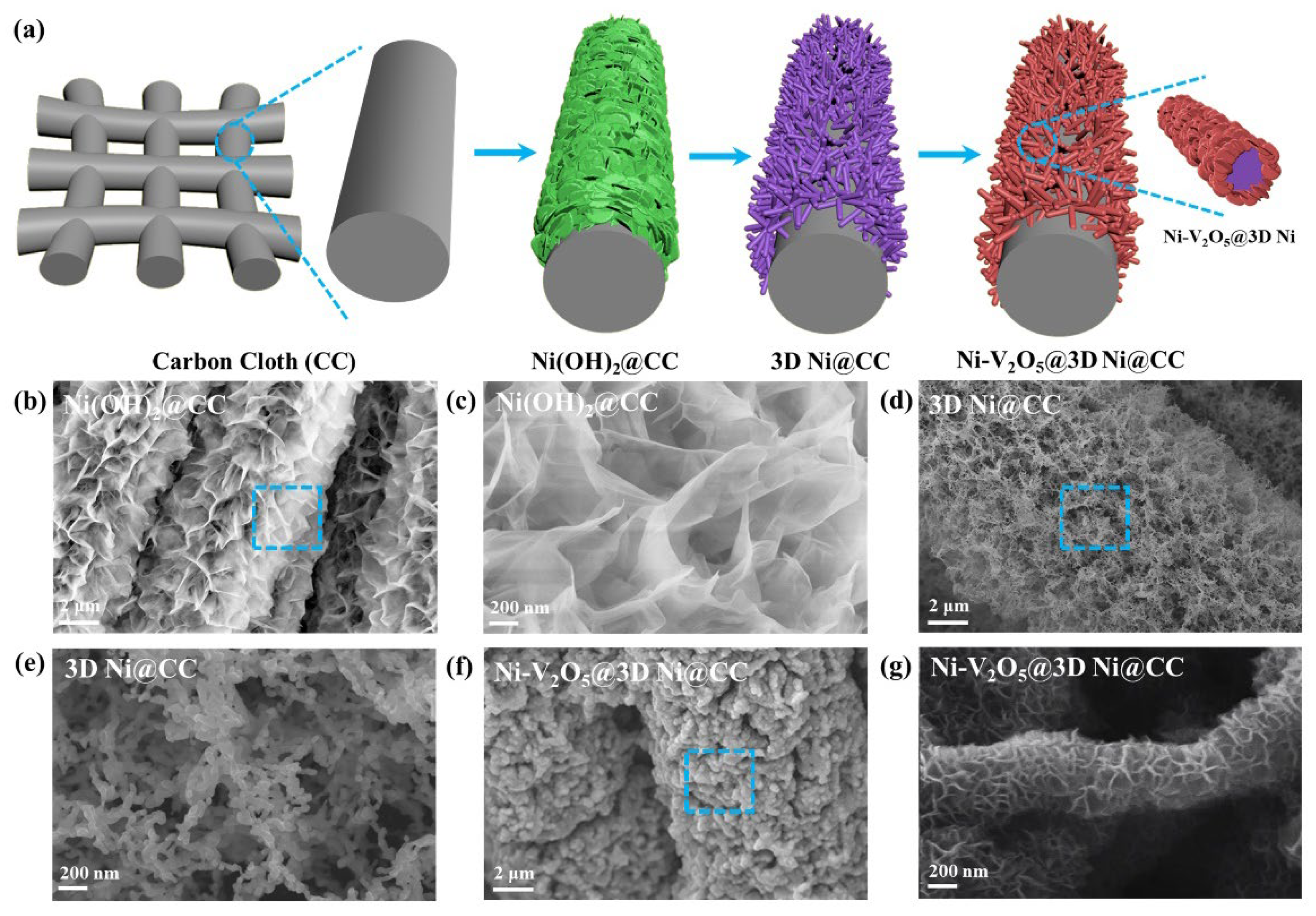
Figure 2.
TEM images with higher magnification of (a) Ni(OH)2@CC, (b) 3D Ni@CC and (c) Ni-V2O5@3D Ni@CC. (d) STEM image and elements distribution of a Ni-V2O5 nanosheet. (e) EELS result of Ni-V2O5 nanosheet taken from the red dashed box in Figure 2d.
Figure 2.
TEM images with higher magnification of (a) Ni(OH)2@CC, (b) 3D Ni@CC and (c) Ni-V2O5@3D Ni@CC. (d) STEM image and elements distribution of a Ni-V2O5 nanosheet. (e) EELS result of Ni-V2O5 nanosheet taken from the red dashed box in Figure 2d.
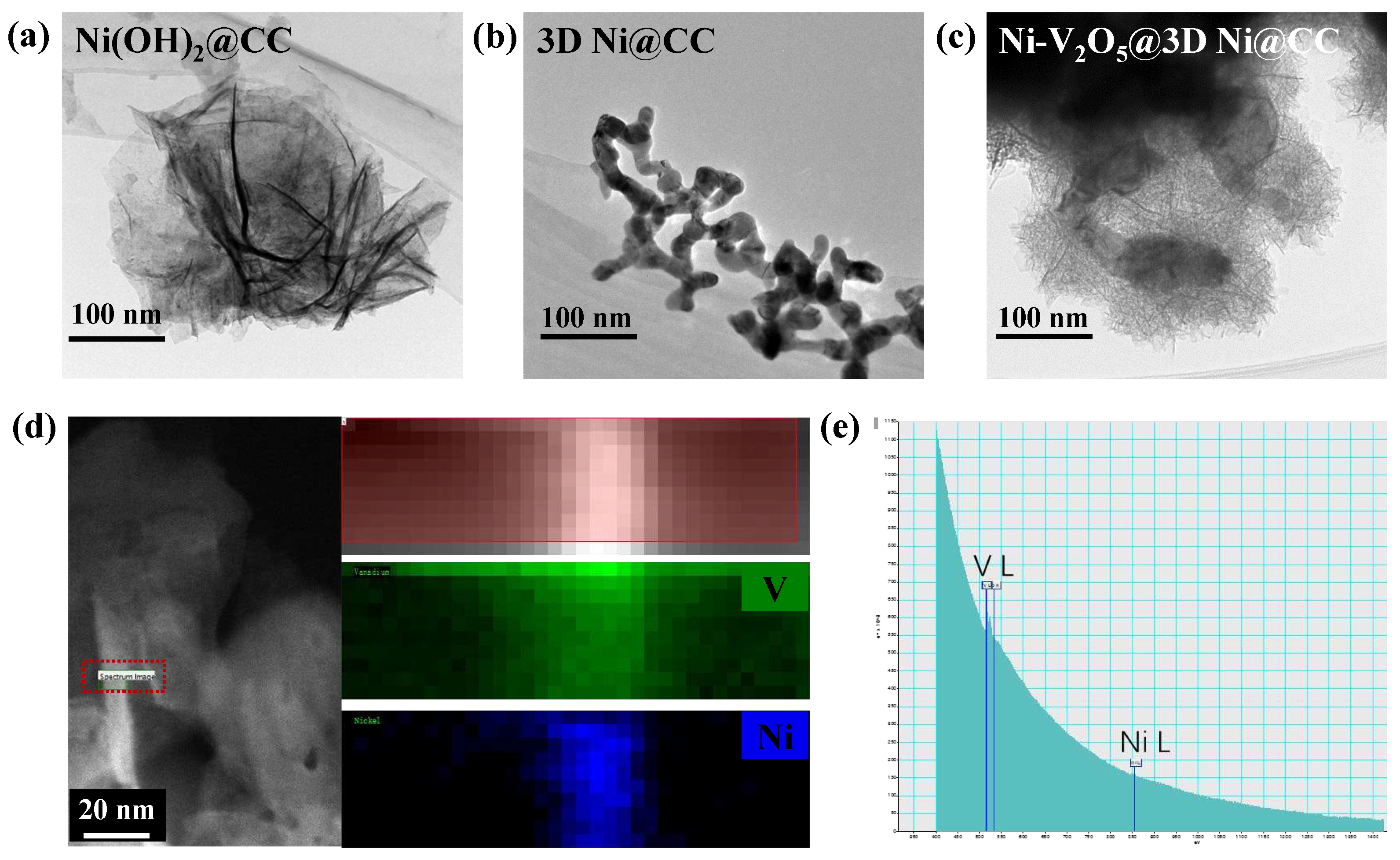
Figure 3.
(a) XRD patterns of V2O5@CC and Ni-V2O5@3D Ni@CC. (b) XPS spectra of 3D Ni@CC and Ni-V2O5@3D Ni@CC.
Figure 3.
(a) XRD patterns of V2O5@CC and Ni-V2O5@3D Ni@CC. (b) XPS spectra of 3D Ni@CC and Ni-V2O5@3D Ni@CC.
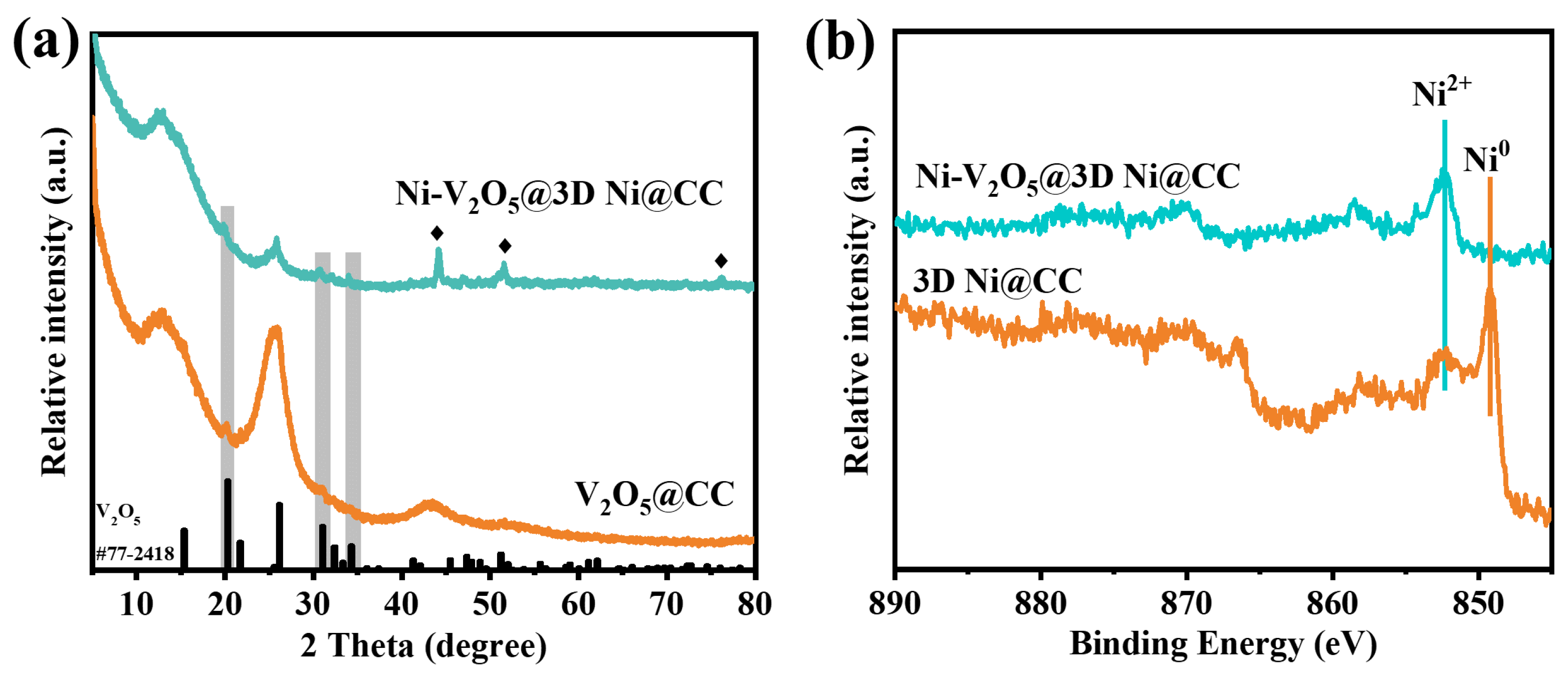
Figure 4.
(a) CV curves of V2O5@CC-based ZIB (0.3-1.5 V) and Ni-V2O5@3D Ni@CC-based ZIB (0.3-1.8 V) at a scan rate of 1.0 mV s-1. (b) Galvanostatic charge-discharge (GCD) curves of V2O5@CC-based ZIB and Ni-V2O5@3D Ni@CC-based ZIB under a current density of 0.8 A g-1. (c) CV curves of Ni-V2O5@3D Ni@CC-based ZIB at different scan rates from 0.5 to 4.0 mV s-1. (d) GCD curves of Ni-V2O5@3D Ni@CC-based ZIB under different current densities (0.4-4.8 A g-1). (e) Rate capability test of Ni-V2O5@3D Ni@CC-based ZIB under various current densities (0.4-4.8 A g−1). (f) Long-cycle stability test for Ni-V2O5@3D Ni@CC-based ZIB at a current density of 4.8 A g-1.
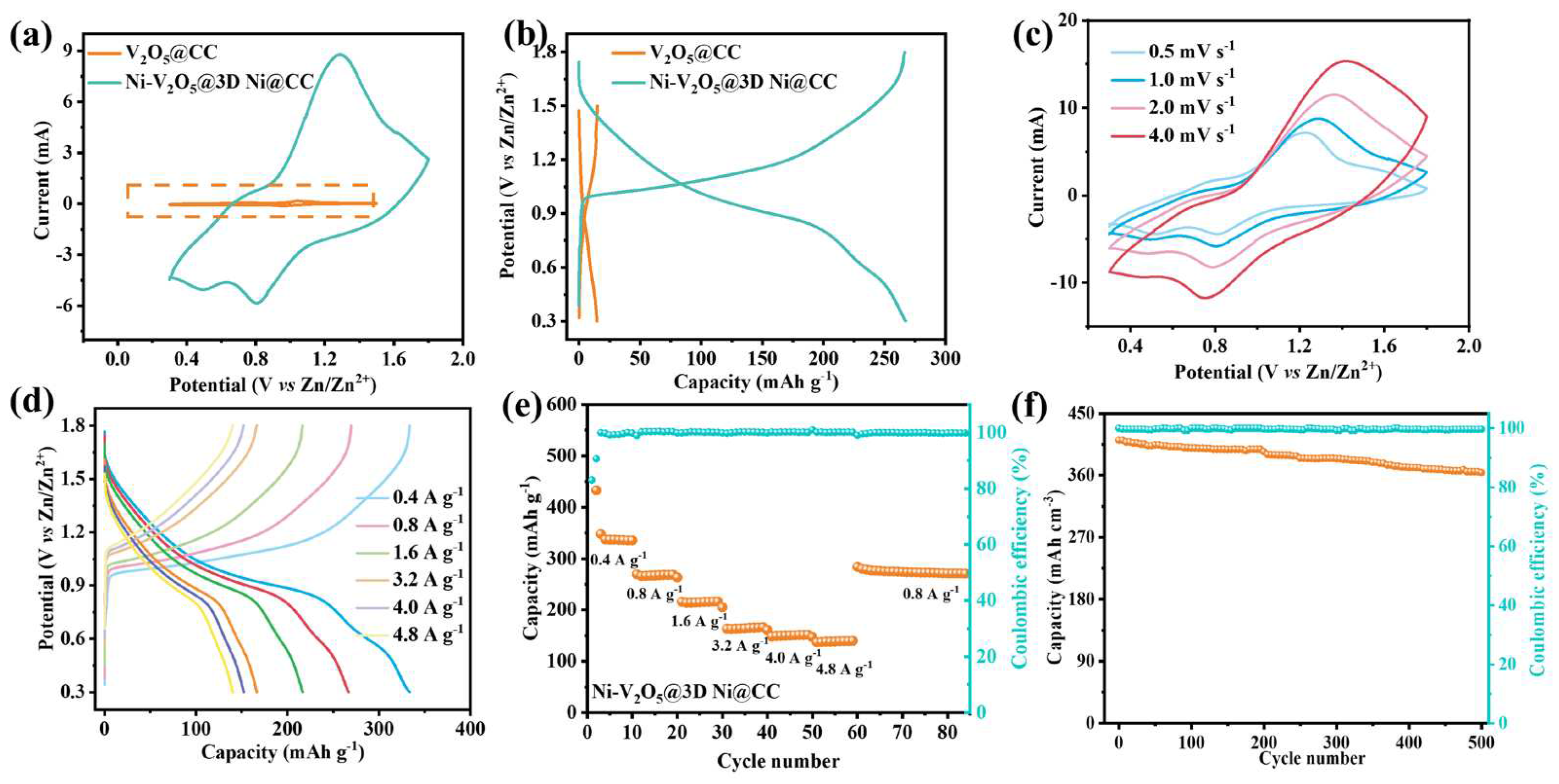
Figure 5.
Ex-situ XRD patterns for Ni-V2O5@3D Ni@CC electrode during charge/discharge process under different potentials at a current density of 0.4 A g-1.
Figure 5.
Ex-situ XRD patterns for Ni-V2O5@3D Ni@CC electrode during charge/discharge process under different potentials at a current density of 0.4 A g-1.
Disclaimer/Publisher’s Note: The statements, opinions and data contained in all publications are solely those of the individual author(s) and contributor(s) and not of MDPI and/or the editor(s). MDPI and/or the editor(s) disclaim responsibility for any injury to people or property resulting from any ideas, methods, instructions or products referred to in the content. |
© 2023 by the authors. Licensee MDPI, Basel, Switzerland. This article is an open access article distributed under the terms and conditions of the Creative Commons Attribution (CC BY) license (http://creativecommons.org/licenses/by/4.0/).
Copyright: This open access article is published under a Creative Commons CC BY 4.0 license, which permit the free download, distribution, and reuse, provided that the author and preprint are cited in any reuse.


