Submitted:
07 December 2023
Posted:
07 December 2023
You are already at the latest version
Abstract
In this paper, an intelligent blind guide system based on 2D LiDAR and RGB-D camera sensing is proposed, and the system is mounted on the smart cane. The intelligent guide system relies on 2D LiDAR, RGB-D camera, IMU, GPS, Jetson nano B01, STM32 and other hardware. The main advantage of the intelligent guide system proposed by us is that the distance between the smart cane and obstacles can be measured by 2D LiDAR based on Cartographer algorithm, thus achieving Simultaneous localization and mapping (SLAM). At the same time, through the improved yolov5 algorithm, pedestrians, vehicles, pedestrian crosswalks, traffic lights, warning posts, stone piers, tactile paving and other objects in front of the visually impaired can be quickly and effectively identified. Laser SLAM and improved yolov5 obstacle identification tests were carried out inside a teaching building on the campus of Hainan Normal University and on a pedestrian crossing on Longkun South Road in Haikou City, Hainan Province. The results show that the intelligent guide system developed by us can drive the wheels and omnidirectional wheels at the bottom of the smart cane, and give the smart cane a self-leading blind guide function like a "guide dog", which can effectively guide the visually impaired to avoid obstacles and reach the predetermined destination, and can quickly and effectively identify the obstacles on the way out. The laser SLAM speed of this system is 25~31FPS, which can realize the short-distance obstacle avoidance and navigation function both in indoor and outdoor envionments. The improved yolov5 helps to identify 86 types of objects, the recognition rate for pedestrian crosswalks and for vehicles are 84.6% and 71.8%, respectively; the overall recognition rate for 86 types of objects is 61.2%, and the obstacle recognition rate of the intelligent guide system is 25-26FPS.
Keywords:
Smart Cane
; Jetson Nano (B01)
; 2D LiDAR
; RGB-D Camera
; Laser SLAM
; Target Recognition
; Cartographer
; Improved Yolov5
1. Introduction
The problem of visual impairment is very common, and there is a growing trend. According to a 2015 survey of visual impairment, an estimated 253 million people worldwide suffer from visual impairment. Of these, 36 million are blind and 217 million suffer from moderate to severe visual impairment [1]. According to the World Outlook Report released by the World Health Organization (WTO) in 2019, at least 2.2 billion people in the world are visually impaired or blind [2]. By 2020, the number of blind people worldwide is estimated to have grown to 43.3 million[3]. It is estimated that 61 million people worldwide will be blind by 2050[3]. According to data from the official website of the Blind Association, China is the country with the largest number of blind people in the world, and the number of visually impaired people exceeds 17.3 million, of which 8 million are completely blind. About 1 in every 120 Chinese people suffer from visual impairment diseases, and about 450,000 visually impaired people are added in China every year. At present, due to the small number of guide dogs in China, most visually impaired people choose to move around with the help of a white cane. However, the traditional white cane is composed of a simple cane body and handle, which realizes a very single function and has a limited range of detection. In recent years, with the continuous maturity of autonomous driving technology, robot autonomous navigation technology, object detection and recognition technology and the rising of intelligent hardware, a new solution to the travel problem of the visually impaired has been provided.
Researchers around the world have made great contributions to the laser and vision sensing smart guide system [4,5,6,7,8,9,10,11,12]. The laser and vision sensing smart canes with laser SLAM, visual SLAM, capable of recognizing the obstacles in front of the visually impaired, recognizing faces and daily necessities, with tracking functions, have been developed and constantly updated. Each type of laser and vision sensing smart cane has its own advantages and disadvantages.
Some smart cane systems have fewer obstacle recognition types, lack of targeted recognition of obstacles on the road, and the system response speed is slow. In this regard, Slade P et al. (2021) [13] proposed an active smart cane based on laser SLAM technology, which was equipped with RPLIDAR-A1 LiDAR, Raspberry PI monocular camera, IMU and GPS. The smart cane uses A* algorithm to plan routes and uses the model yolov3 Tiny to identify stopping traffic signs. An omnidirectional wheel driven by a motor is installed at the bottom of the smart cane, driving the smart cane to swing left and right to guide the visually impaired to bypass obstacles and reach the destination. The smart cane can increase the walking speed of the visually impaired by 18±7%. The main control module of the smart cane is Raspberry PI 4B, and the monocular camera used is the official camera of Raspberry PI, so the real-time target recognition ability and recognition efficiency of the smart cane are not high, and it can recognize less objects. A Carranza et al. (2022) [14] proposed a smart guide system consisting of Raspberry PI 4, Raspberry PI official camera, ultrasonic sensor and speaker. The smart guide system uses TensorFlow Lite deep learning framework, OpenCV vision open source library and yolo algorithm to carry out real-time target detection, and can identify the vehicle in front of the visually impaired person. However, the accuracy rate of the intelligent cane for vehicle recognition is 55%-56%, and the recognition types are few and the recognition accuracy is low. TK Chuang et al. (2018) [15] proposed a Guide Dog Smart Cane with three Raspberry PI 2B, one NVIDIA Jetson TX1 and three cameras installed on the system. Three cameras are used for environmental data collection, with one camera input used to perform predictive tasks. The Guide Dog Smart Cane uses a deep convolutional neural network (CNN) to identify preset tracks to guide the visually impaired to their destination. But the system lacks the ability to identify other obstacles, and its ability to work is weakened when deviating from the preset trajectory. In terms of targeted obstacle recognition, Y Jin et al. (2015) [16] proposed a smart cane with face detection and recognition functions. The system is equipped with a camera mounted on eyeglasses and uses an Adaboost iterative algorithm to detect and recognize the faces of strangers around the visually impaired person and generate a unique vibration pattern of each person's face to feed back to the visually impaired person, helping him or her to know who is in front of him. But the system can only recognize faces and only a limited number of people. K Jivrajani et al. (2022) [17] proposed an AIoT-based smart cane, which uses Raspberry PI 3 as the main control module and OmniVision OV5647 as the camera module. A new network structure combining mobilenetv2 and yolov5s is proposed, and the obstacle detection rate is 91.7%. The system can identify some daily necessities, but the system lacks the ability to identify obstacles on the road. To solve the problem of slow system response, H Hakim et al. (2019) [18,19] proposed an indoor visually impaired assistance device based on two-dimensional laser SLAM. The smart cane uses Raspberry PI 3B+ as the main control module to fix the Neato XV-11 LiDAR, Raspberry PI camera and ultrasonic sensor to the cane. The smart cane uses LiDAR Hector SLAM to build a two-dimensional map of the environment around the visually impaired person, and uses A* path planning algorithm to generate the optimal path on the two-dimensional map. At the same time, yolov2 algorithm was used to identify obstacles such as indoor tables and chairs, but the identification process ran online in the cloud, and the detection frame rate was only 0.6FPS, making the recognition rate of the system low. B Kumar (2021) [20] proposed a ViT Cane, a visual assistant for the visually impaired. The system consists of Raspberry PI 4B, Raspberry PI original camera V2 and four motors, and uses Vision Transformer architecture to detect obstacles such as garbage cans, street signs, bicycles and traffic cones in front of the visually impaired. Because the ViT Cane cannot recognize fast moving vehicles on real roads, the system's response rate is slow, so it does not have the ability to be used on real roads. N Kumar et al. (2022) [21] proposed a smart guide system based on YOLOv5, which uses Raspberry PI 3 as its main control. The time required for image data analysis and processing varies from less than 1s to 3s, so there is a certain delay in the work process.
Some smart cane systems lack the function of actively guiding the visually impaired. In this regard, Z Xie et al. (2022) [22] proposed a multi-sensory navigation system that combines yolo and ORB-SLAM. The system consists of Raspberry PI 4B, RealSense RGB-D camera and vibration motor array, where the RGB-D camera receives real-time color image information and depth information, activating the improved ORB-SLAM in ROS system for map construction and global path planning, using yolov3 algorithm and DarkNet53 network to detect obstacles encountered by the visually impaired while walking. The system can obtain a relatively high mAP value, up to 55.3, while maintaining 35 FPS performance. However, the smart cane lacks a driving device, the navigation ability of the motor array tactile feedback navigation is weak, and lacking the function of actively guiding the visually impaired. L Udayagini et al. (2023) [23] proposed a smart cane with Raspberry PI 3 as the main control board, combining HCSRCO4 ultrasonic sensor, Raspberry PI official camera module, and acceleration sensor and humidity sensor. The smart cane adopted yolov3 algorithm to recognize the faces of relatives of the visually impaired and surrounding vehicles and other obstacles. However, the design of the smart cane is too simple, with weak objects recognition capability and no active navigation function. Cang Ye et al. (2014) [24] proposed a smart cane named CRC, using Gumstix Overo computer as the main control board and SR4000 3D-TOF camera for attitude estimation and object recognition. The object recognition method is based on Gaussian mixture model (GMM), which can effectively detect building structures such as indoor stairs, corridors and rooms, as well as objects such as tables and computer monitors. CRC smart cane is equipped with an active rolling tip with encoder servo motor and electromagnetic clutch that can change direction, but the active rolling tip can only provide navigational steering, and lacks the function of actively guiding the visually impaired to avoid obstacles and navigate. S Agrawal et al. (2022) [25] proposed a visual SLAM smart cane with tactile navigation. The system is equipped with RealSense D455 with RGB-D sensing and RealSenseT265 with IMU for target location and path planning. The smart cane can identify empty chairs in public indoor spaces that meet common social preferences, and passively guide visually impaired people to and sit on these empty chairs in the form of touch. On average, the smart cane was able to find a seat within 45 seconds, and found an empty chair that matched social preferences 83.3% of the time. However, the Visual SLAM smart cane lacks the ability to obtain other information in the environment, so the smart cane cannot measure the distance such as to the obstacles ahead, without navigation guide function, and can not actively guide the visually impaired person to the empty chair. H Zhang and C Ye et al. (2017-2018) [26,27] developed an indoor visual SLAM real-time path finding navigation system for visually impaired people based on SR4000 3D-TOF camera, and proposed a new two-step pose image SLAM method. The two-step pose image SLAM method can reduce the 6-DOF attitude error of the device and shorten the calculation time. The system uses A* algorithm for global path planning to find the shortest path from the starting point to the end point, and uses attitude estimation and floor plans to locate the visually impaired indoors, as well as to recognize three-dimensional objects. However, the smart cane guides users through voice interface navigation commands, so it lacks the function of actively guiding the visually impaired. H Zhang et al. (2019) [28] proposed a visual inertial SLAM navigation aid smart cane for the visually impaired combined with the RealSense R200 camera and VectorNav VN100 IMU module, whose appearance is similar to that of [24]. Jin et al. (2009) [29] proposed EYECane guide system, which notifies the visually impaired through auditory information and enables them to passively listen to the path information planned by the system to walk. Based on Viola Jones and TensorFlow algorithm, U Masud et al. [30] proposed a smart cane composed of Raspberry PI 4B and Raspberry PI camera (V2) that can recognize faces and surrounding obstacles. But the smart cane lacks a driving device, so it can only navigate passively. K Suresh (2022) et al. [31] proposed a smart cane with image recognition function with Arduino as the main control module. The smart cane uses yolov4 algorithm to identify people, mobile phones and stairs, and the recognition accuracy rate is above 90%, and the movement speed of the visually impaired can be increased by 15% to 20%. But the smart cane still lacks active guidance.
Some smart cane systems need to be assisted by electronic mobile devices and need an external computer as the main control. In terms of the smart cane system that needs to be assisted by electronic mobile devices, Q Chen et al. (2017) [32] proposed a smart cane system named CCNY, which is based on the built-in camera, gyroscope and accelerometer of Google Tango device to realize the visual-inertial SLAM function of path planning. The sense of touch is then used to feed navigation instructions back to the visually impaired to help them navigate to their destination in unfamiliar or complex indoor environments. L Jin et al. (2020) [33] proposed a CIP-VMobile navigation-assisted smart cane based on the iPhone 7 smartphone Visual Inertial odometer (VIO), which uses iPhone 7 as a sensing and computing platform. The iPhone 7's rear camera and LSM6DSR-iNEMO inertial measurement unit are used as imaging and motion sensors to enable visual inertial fusion SLAM, enabling the system to plan the shortest path to a destination based on the location of the visually impaired and a pre-stored 2D floor plan. The system uses a DC motor to drive a smart cane rolling tip to guide the visually impaired along a planned path to a destination. As the smart cane system requires an external computer as the main control, PF Alcantarilla and A Rodriguez et al. (2012) [34,35] proposed the combination of visual SLAM and dense scene flow to improve the positioning ability of the guide system in a dynamic environment. However, the hardware part of the system needs to be worn on the visually impaired, and external communication cables need to be connected to the laptop, making it difficult to walk with the visually impaired. In addition, if the system is operating without moving target detection, the error between the camera's estimated motion trajectory and the actual trajectory will be large. H Takizawa et al. (2015) [36] proposed a system consisting of a Kinect depth camera, numeric keypad and haptic feedback device. The system uses the Kinect depth camera to obtain color images and depth data around the visually impaired, identify objects such as floors, chairs and stairs near the smart cane, search for objects the visually impaired wants to look for, and then feed the search results back to him through the haptic device. However, the smart cane is connected to the laptop through a wire, and there may be a risk of wire disconnection when the visually impaired person uses too much tension with the smart cane. EJ Taylor (2017) [37] proposed an obstacle avoidance system for the visually impaired based on three-dimensional point cloud processing. The system is based on the Robot Operating System (ROS) and Open source Point Cloud Library (PCL), with the Asus Xtion Pro Live depth camera and wireless Wii remote installed on the smart cane. The depth camera uses ROS PointCloud2 to obtain a semantic image of the visually impaired person. However, the system is unable to detect objects above the waist, and the visually impaired people need to touch objects when navigating. Although the system can be operated wirelessly, the visually impaired need to carry a laptop when using it.
In summary, the current laser and vision sensing smart cane has the following problems: (1) There are few obstacle recognition types, and lack of targeted identification of obstacles on the road, and the system response is slow; (2) Lack of active guidance for the visually impaired; ③ Need an external computer as the main control and need to be assisted by electronic mobile devices. Therefore, in view of the above problems, our starting point is to increase the identification types of obstacles on the road, improve the real-time response speed of the system, improve the actively guiding capability for the visually impaired without external devices, and develop our smart guide system by combining Cartographer and improved yolov5 algorithm.
In this paper, we propose a smart cane guide system based on 2D LiDAR and RGB-D camera sensing. The blind guide system combines Cartographer and the improved yolov5 algorithm to realize navigation and target recognition functions. We have transformed the commonly used travel AIDS (white cane) for the visually impaired, endowed them with intelligence, and equipped the intelligent guide system on the guide cane to better solve problems such as obstacle avoidance, navigation and obstacle recognition encountered by the blind in the process of travel. Our work can be summarized as follows:
(1) The Cartographer algorithm was used to enable the smart cane to acquire laser SLAM function to achieve navigation capabilities, and the improved yolov5 algorithm was used to enable the smart cane to identify obstacles in front of the visually impaired person.
(2) The smart cane system and structure has been designed based on by 2D LiDAR sensing and RGB-D camera, and the intelligent blind guide system was equipped on the smart cane for actual function testing.
(3) The field test shows that the intelligent guide system is real-time and effective in helping the visually impaired to navigate indoors and outdoors and identify obstacles.
2. System design
This work develops an intelligent guide system with navigation and object recognition functions to help the visually impaired navigate to the preset destination and identify obstacles on the road. The intelligent guide system is composed of four parts: data acquisition module, central processing module, driving module and power supply module. The framework of the intelligent guide system is shown in Figure 1.
2.1. Smart cane structure design
The smart cane in literature [13] moves forward through the left and right swing of the omnidirectional wheel. Its way of moving forward is based on the process of the visually impaired person holding the ordinary blind cane swinging left and right and tapping the ground to detect the obstacles ahead. This way of moving forward is conducive to the visually impaired who have been used to the ordinary cane to quickly master the use of this intelligent cane, but in the case of the smart cane already has a sensor to detect the road and obstacle information in front of the smart cane, the efficiency of moving forward will be affected. The smart cane robot in literature [38] and [39] uses a rod similar to a white cane to connect to a robot car, and drives the rod through the movement of the robot car to drive the visually impaired person to walk. At this time, the robot car with two wheels is equivalent to acting as an "intelligent guide dog" to pull the visually impaired person to walk, but this way of moving will make the visually impaired person who is used to holding the ordinary white cane not adapt to being pulled. Inspired by the literatures [13,38] and [39], we combined their advantages and designed the laser and vision sensing smart cane structure by using the omnidirectional wheel and two differential wheels to cooperate with each other.
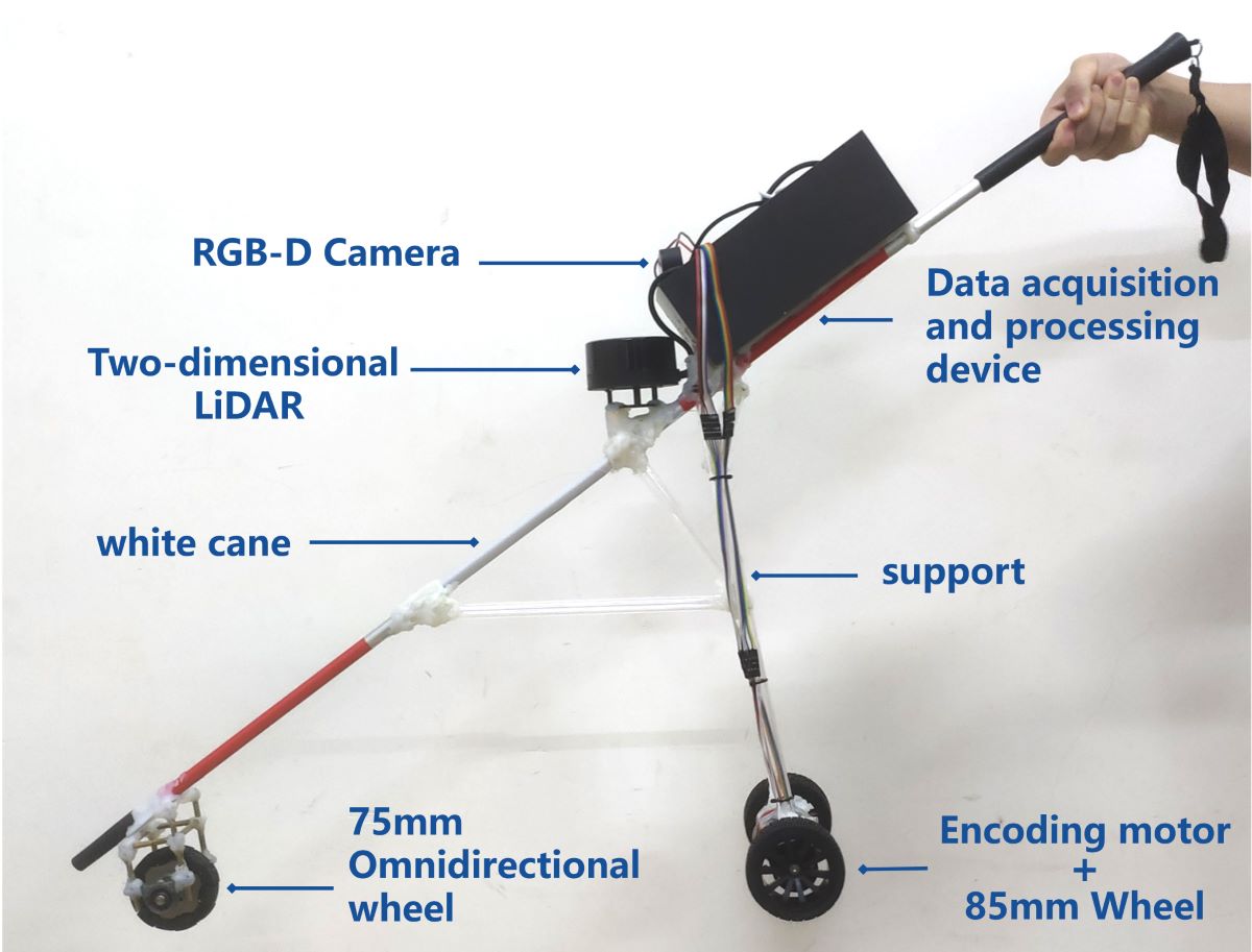
In this paper, Soildworks-2021 3D CAD software is used to design the appearance structure of the laser and vision sensing smart cane, and its appearance design is shown in Figure 2. The smart cane adopts lightweight and easy to carry and replace components, mainly composed of data acquisition and processing devices (LiDAR, RGB-D camera, IMU, GPS), white cane, bracket, omnidirectional wheel, coding motor, wheel, lithium battery. The omnidirectional wheel and two main wheels of the smart cane are in contact with the ground and jointly support the whole smart cane, which can ensure that the smart cane can be in a stable state without interference from external forces, and the omnidirectional wheel and main wheels give the smart cane active navigation ability. In addition, the height and center of gravity of the smart cane can be adjusted according to the height of the visually impaired, so that he/she can use the smart cane more easily.
2.2. Smart cane system hardware
The hardware design of the smart cane system includes: main control module: NVIDIA Jetson Nano B01 (4GB); Data acquisition module: M10P TOF 2D LiDAR, Gemini binocular depth camera, N100N 9-axis inertial navigation module, G60 GPS Beidou dual-mode positioning module; Drive module: STM32F407VET6 microcontroller, 500-wire AB phase GMR(Giant Magnetoresistance) encoder, double bearing 75mm diameter omnidirectional wheel, two 85mm diameter non-slip rubber tires; Power module: 12V-9800MAH lithium battery. The hardware parameters of the intelligent guide system are shown in Table 1.
The central processing module Jetson Nano B01(4GB) can receive the environmental information data of the data acquisition module and analyze and process the data. After data analysis and processing, the instructions are transmitted to the driving module STM32F407VET6, so as to drive the smart cane walking. The LiDAR can obtain the position and distance information of the obstacles ahead, achieve synchronous positioning and composition (SLAM) function, and enable the smart cane to avoid obstacles and go to the destination according to the small-range planned route. The depth camera can identify what object is the obstacle in front of the smart cane, identify the tactile paving, pedestrian crossing, traffic lights, warning posts and stone pillars around the visually impaired person, and can detect the ground potholes, steps and low height obstacles that the LiDAR cannot detect. The Inertial Measurement Unit (IMU) is composed of three-axis gyroscope, accelerometer and magnetometer. The IMU module can detect the attitude information during the movement of the smart cane and prevent the deviation caused by the accumulated error during the movement of the smart cane. The GPS module can detect the geographical location of the smart cane in real time, provide a large range and long distance navigation information for the smart cane, and record the moving trajectory of the smart cane. The microcontroller STM32F407VETb is used to accept the instructions transmitted by the central processing module and drive the GMR high-precision coding motor to drive the non-slip wheel and the omnidirectional wheel. The physical appearance structure of the laser and vision sensing smart cane is shown in Figure 3, and the hardware structure of the intelligent blind guide system is shown in Figure 4.

Table 1.
Hardware parameters of intelligent guide system.
| Hardware | Hardwaretype | parameters and dimensions |
| Main control module | Jetson Nano B01(4GB) | CPU:ARM Cortex-A57 GPU:128-core Maxwell |
| 2D LiDAR | Leishen Intelligent System M10P TOF |
Detection distance radius: 0-25m Measurement accuracy: ±3cm Detection Angle: 360° Scanning frequency: 10HZ |
| RGB-D camera | ORBBEC Gemini Pro | Detection accuracy :1m±5mm Detection field of view: H71.0°xV56.7° |
| IMU | WHEELTECN 100N | Static accuracy: 0.05°RMS Dynamic accuracy: 0.1°RMS |
| PGS | WHEELTEC G60 | Positioning accuracy :2.5m |
| Microcontroller | STM32 | STM32F407VET6 |
| Encoding motor | WHEELTECN GMR | 500 line、AB phase GMR |
| Omnidirectional wheel | WHEELTEC omni wheel | Diameter :75mm Width: 25mm |
| Wheel | WHEELTEC 85mm | Diameter :85mm Width: 33.4mm Coupling aperture: 6mm |
| Battery | 12V-9800MAH | Size: 98.6×64×29mm3 |
| White cane | j&x White cane | Length: 116cm Diameter: 1.5cm |
2.3. Working process of the intelligent guide system
The working process of the smart cane is as follows: When the visually impaired person uses the smart cane, he/she turns on the power switch of the smart cane to supply power to each module of the smart cane, so that the smart cane can enter the working state. The visually impaired person can input the destination to the smart cane system through the voice module; The central processing module starts the data acquisition module to collect the obstacle distance and image data of the environment around the visually impaired person. After the data processing and analysis, the central processing module transmits the instructions to the drive module, so that the smart cane can realize positioning, obstacle avoidance, navigation, attitude detection and other functions in real time indoors and outdoors, and identify the obstacles ahead. The visually impaired person is guided by the smart cane to get around the pedestrians and obstacles on the road and reach the destination. At the same time, GPS will record the time node and travel trajectory of the visually impaired when they go out. When the visually impaired person stops using the smart cane, the charger can be plugged into the smart cane to charge the battery.
3. Materials and Methods
3.1. Cartographer algorithm
The commonly used LiDAR based simultaneous localization and mapping (SLAM) technology can accurately measure the distance and angle of the obstacle point of the visually impaired and generate an environment map that is convenient for the navigation of the intelligent guide system,which has become an indispensable technology in the field of guide blindness. The two-dimensional laser SLAM scheme currently applied in the field of blindness includes Gmapping[40], Hector SLAM[41], Cartographer[42]. Compared with other 2D laser SLAM schemes, Cartographer provides accurate solutions for positioning and map construction, using global map optimization cycles and local probabilistic map updates. This makes the application Cartographer's laser SLAM system more robust to environmental changes [43]. Therefore, in this paper, we use Cartographer algorithm to realize the positioning, obstacle avoidance and navigation functions of the intelligent guide system.
Cartographer[44] is an open source algorithm of laser SLAM based on optimization methods developed by Google. The Cartographer algorithm consists of two independent but related subsystems: the local SLAM (front-end architecture) and Global SLAM (back-end architecture). In order to generate better subgraphs, the front-end architecture is designed to generate better subgraphs. Back-end structure for better closed loop constraints on subgraphs. The Cartographer algorithm is mainly used to improve the accuracy of drawing construction and the efficiency of back-end optimization. Its algorithm architecture is shown in Figure 5.
3.2. Improved yolov5 algorithm
Yolo(You Only Look Once)[45,46,47] is an object detection algorithm. Yolov5[48] was proposed by Ultralytics, and yolov5 algorithm has been widely used in the assistance system for the visually impaired with target recognition function. It is used to identify objects such as pedestrian crossings [49,50], traffic lights [51], buses [52], straight or left and right paths [53], clothing defects [54], stairs and roads [55], faces and money [56], and indoor fires [57]. Since the official model of yolov5 alone cannot meet the requirements of this work to identify all obstacles on the road and improve the training speed of yolov5 model, in this paper, we increased the training set of the guide system model and added the attention machine [58] system to the yolov5 algorithm to make improvements. We replace C3 layer in the Backbone of yolov5 algorithm with CBAM (Convolutional Block Attention Module) [59]. CBAM Attention mechanism is composed of Channel Attention Module (CAM) and Spatial Attention Module (SAM). Channel attention is used to deal with the distribution relationship of feature graph channels. Spatial attention can make the neural network pay more attention to the pixel region that plays a decisive role in image classification and ignore other unimportant pixel regions. CBAM attention mechanism allocates attention to both channel and space, which enhances the effect of attention mechanism on the overall model performance. The improved yolov5 algorithm architecture is shown in Figure 6.
4. Experiment and Results
4.1. Simulation experiment
The computer processor used in the simulation experiment of this work is Intel(R) Core(TM)i5-11300H. We installed the Ros-Nocetic open source robot operating system under Ubuntu 20.04 Linux64-bit operating system on virtualbox 6.1.16 open source virtual Machine software in the calculator processor.
In Ros-Nocetic simulation experiment, URDF file was used to create a simulated intelligent cane model, and Xacro (XML Macros) file was used to optimize the macro encapsulation of URDF file, so as to optimize the code structure of URDF file and improve the code reuse rate of URDF file. Then the motor control board Arbotix function is invoked to realize the movement of the simulated smart cane model in Gazebo and RVIZ in Ros-Nocetic. The smart cane model is composed of two environmental information sensors, LiDAR and RGB-D camera, blind cane, data acquisition and processing device, support, all-directional wheel and two main wheels. The simulated smart cane model is designed similarly by referring to the appearance design of the smart cane in Chapter 2.1 of this paper. The simulated URDF model design drawing and the side view of all sides are shown in Figure 7, and the simulated URDF model hierarchical relationship is shown in Figure 8.
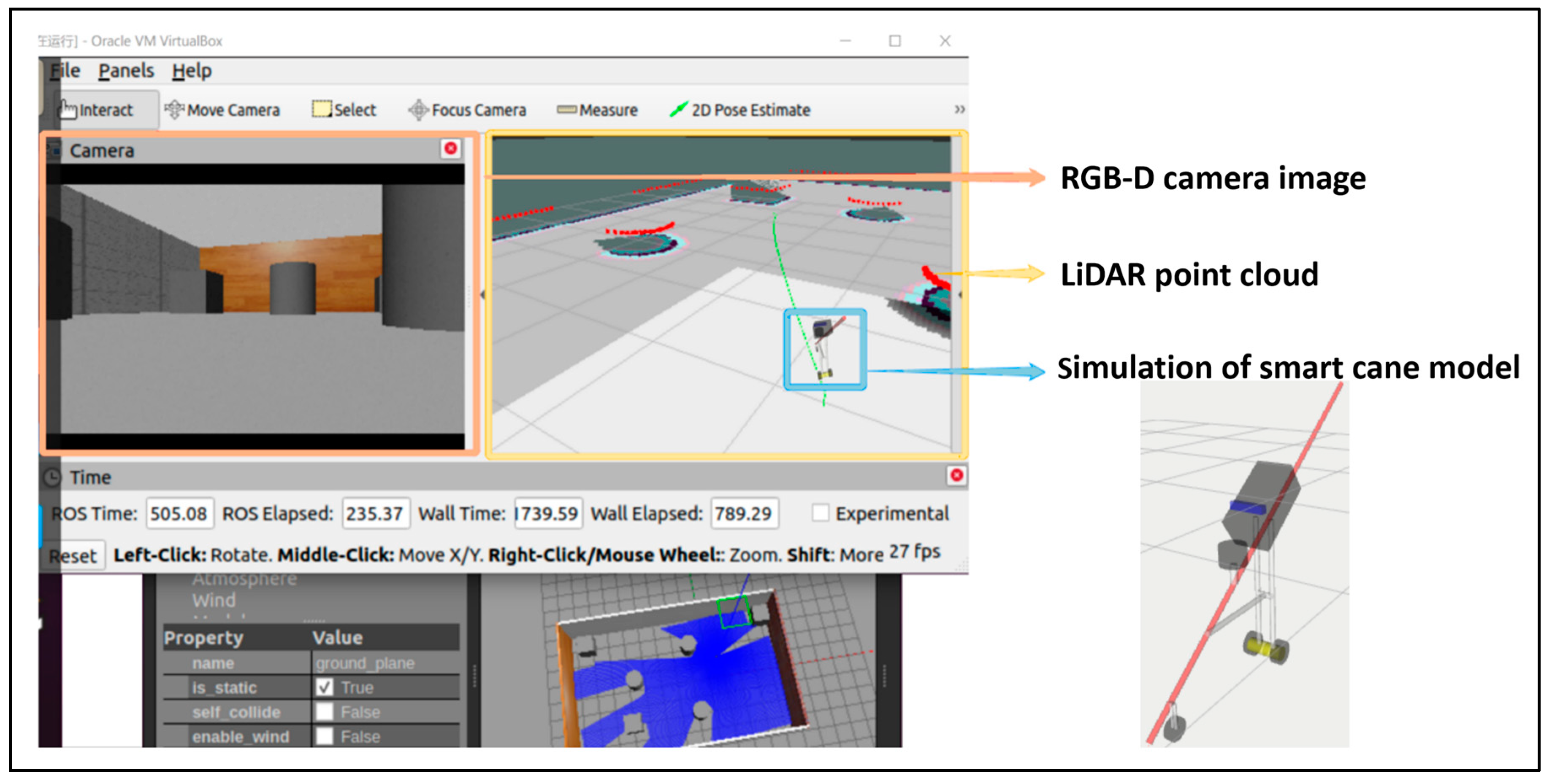
We created the simulation environment of the smart cane system in Ros-Nocetic's Gazebo, added several simulated obstacles of different shapes to the simulation environment, and then displayed the simulation environment and the simulated smart cane URDF model in Ros-Nocetic's RVIZ. We set the target point through 2D Nav Goal in RVIZ, and constructing the simulated environment map with the simulated smart cane URDF model by LiDAR sensor and planned the route by Cartographer algorithm. The simulated environment picture information in front of the simulated smart cane was obtained by RGB-D camera. By avoiding obstacles and following the path planned by the system (green dotted line) to the preset destination, the simulated laser SLAM is implemented at a speed of 26-27FPS. The simulation of smart cane to achieve laser SLAM is shown in Figure 9.
Figure 7.
Simulated URDF model of smart cane: (a) Main view; (b) Rear view; (c) Vertical view; (d) Bottom view ; (e) Left view; (f) Right view.
Figure 7.
Simulated URDF model of smart cane: (a) Main view; (b) Rear view; (c) Vertical view; (d) Bottom view ; (e) Left view; (f) Right view.
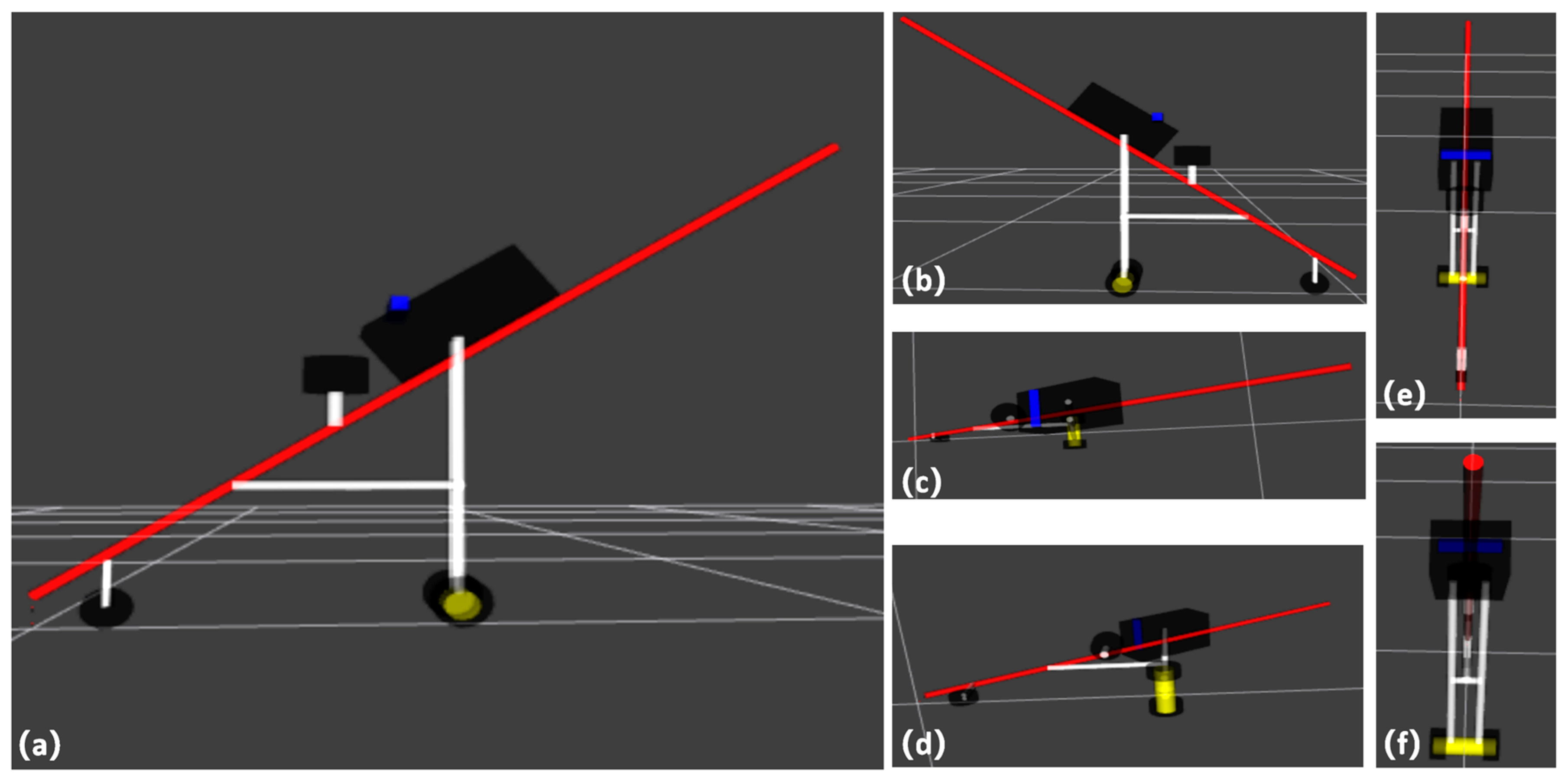
Figure 8.
The simulated URDF hierarchical diagram of smart cane.
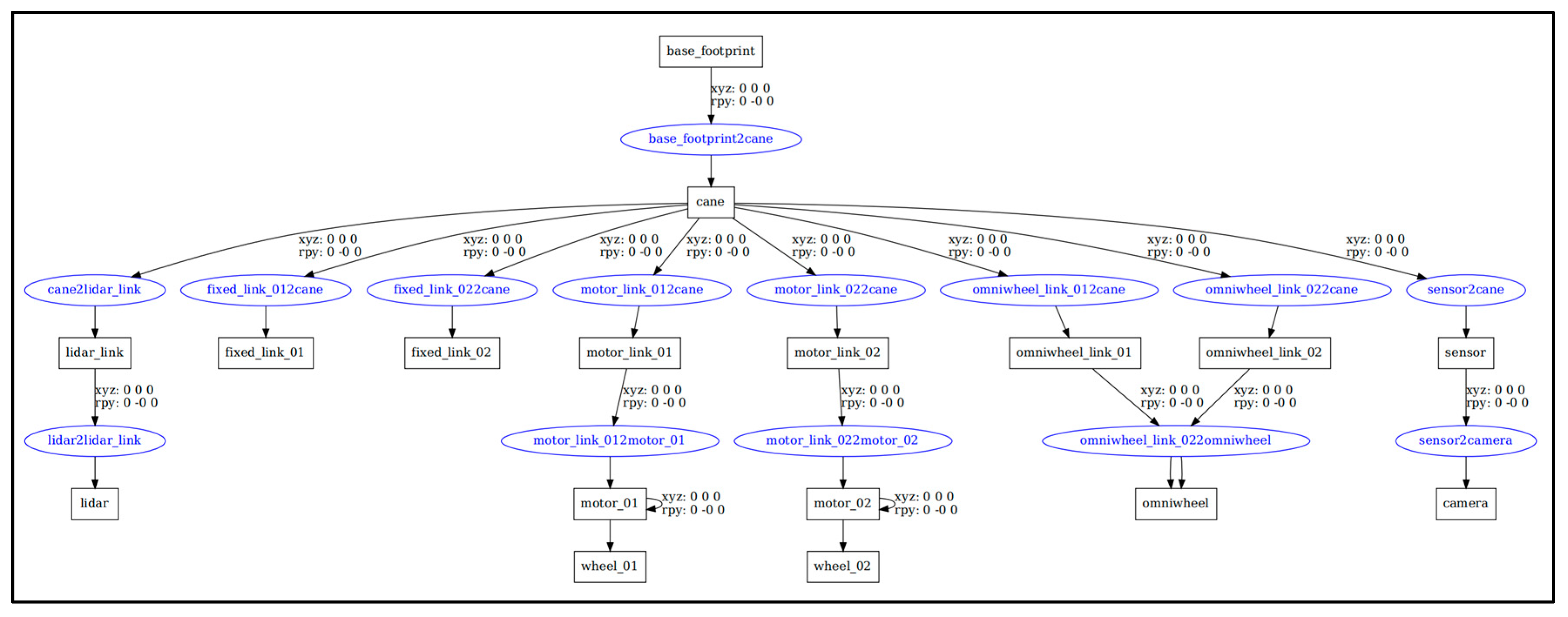
Figure 9.
Simulation of smart cane to achieve laser SLAM (green dotted line is the path of system planning).
Figure 9.
Simulation of smart cane to achieve laser SLAM (green dotted line is the path of system planning).
4.2. Laser SLAM experiment
In our laser SLAM experiment, Ubuntu 18.04 LTS64-bit operating system is deployed on Jetson nano B01, the main control module of the smart cane, and then Melodic-ROS is installed on the Ubuntu system. And the Jetson nano B01 was externally connected to the M10P TOF 2D Lidar. We used Cartographer algorithm on Melodic-ROS to realize the laser SLAM function, and set target points through 2D Nav Goal in RVIZ in Melodic-ROS, so that the smart cane can sense and avoid obstacles, and plan the route to the preset destination.
We simulated the scene of visually impaired person walking in the corridors and floor passages of teaching buildings in the campus of Hainan Normal University. The testers closed their eyes and held the smart cane in their hands to simulate the field test of visually impaired person using the smart cane. The laser SLAM field test of the smart cane is shown in Figure 10. The smart cane system builds the map and realizes the navigation function of the surrounding environment on the corridor and floor passage of the teaching building. In the field test, the laser SLAM rate of the smart cane system is 25~31FPS. Although there is some delay in the process of field mapping and navigation, it does not affect the real-time mapping of the surrounding environment. The test results show that the smart cane system can indeed realize laser SLAM by using Cartographer algorithm on 2D LiDAR, thus realizing map construction of the environment around the visually impaired person and realizing short-distance obstacle avoidance navigation.
4.3. The improved yolov5 algorithm realizing obstacle detection
In this work, an improved yolov5 algorithm is used to achieve obstacle detection. The computer processor used in the training experiment of the improved yolov5 obstacle detection model is Intel(R) Core(TM)i5-11400F, and the GPU graphics card is NVDIA GeForce RTX 2060. We conducted yolov5 obstacle detection model training on the collected and labeled obstacle data set in cuda 11, minicancanda 3 environment management tool, python 3.10, pytorch 2.0.1 and other environments. We added the Convolutional Block Attention Module (CBAM) to the official code of the yolov5 algorithm V6.0. CBAM is a lightweight and general feedforward convolutional neural network attention module. It focuses on the target object information that is more critical to the current task, reduces the attention to other non-target object information, and can even filter out irrelevant information to improve the efficiency and accuracy of task processing, so as to improve the overall performance of obstacle recognition model.
First, 104 videos were collected on multiple sections of Longkun South Road, Qiongshan District, Haikou City, Hainan Province, and 5337 pictures containing effective obstacle information were captured from the collected videos (including 4137 in the training set and 1200 in the test set). LabelImg software was used to label all the pictures in the obstacle training set. A total of 13,193 annotation boxes ( 6 types) of self-made data sets "traffic lights (green light state), traffic lights (red light state), pedestrian crossings, warning columns, stone pillars, tactile paving" were labled. Our overall guide data set uses COCO 2017 official data set (80 categories: pedestrians, vehicles, etc.) plus self-made obstacle data set (6 categories), with a total of 86 categories of objects and 121,308 images. The total data set of this intelligent guide system is shown in Figure 11.
Then, the total data set of the intelligent guide system was trained with the improved yolov5 algorithm. The initial training design was 300 training rounds (epoch =300), and four pictures (epoch size=4) were input into the neural network each time. The final result was a total of 300 rounds of training (epoch=300), each training round lasted about 35 minutes and 30 seconds, and the total training time was 182.709 hours. The improved yolov5 obstacle recognition model of the guide system we need is obtained through training. The obstacle recognition model results trained by the improved yolov5 are shown in Figure 12. Therefore, the obstacle model trained in this work can identify 86 types of objects. It can effectively recognize the target of pedestrians, motorcycles, cars, warning posts, stone piers, pedestrian crossings, traffic lights (green and red), tactile paving, among others. According to the analysis of the trained improved yolov5 model, the recognition rate of the improved yolov5 model for pedestrian crossing is 84.6% and the recognition rate for vehicles is greater than 71.8%. The overall recognition rate of the system for 86 types of objects is 61.2%. The recognition rate, recall rate, mAP and mAP50-95 of obstacle targets on some roads of the improved yolov5 model are shown in Table 2.
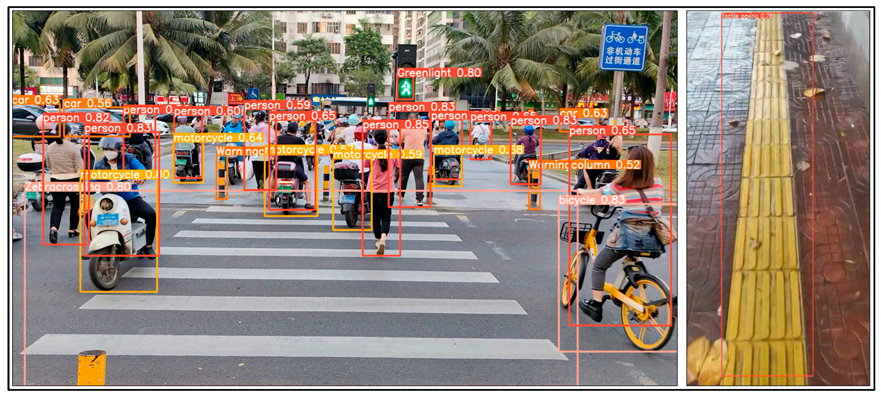
Next, we conducted training on the improved yolov5 obstacle recognition model on the computer processor Intel(R) Core(TM)i5-11400F, GPU graphics card is NVDIA GeForce RTX 2060, The inference was carried out in cuda 11, minicancanda 3 environmental management tool, python 3.10, pytorch 2.0.1 and other environments, and the inference results showed that the intelligent guide system could effectively identify objects such as pedestrians, vehicles, tactile paving, pedestrian crossings, and traffic lights on the road. The reasoning results of the improved yolov5 obstacle recognition model are shown in Figure 13.
Figure 12.
Results of obstacle recognition model trained by improved yolov5.
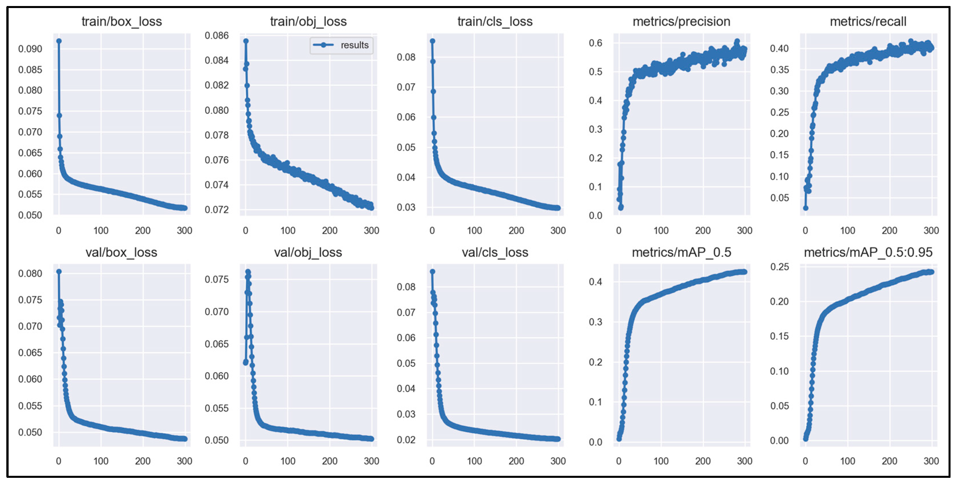
Table 2.
The recognition rate, recall rate, mAP and mAP50-95 of obstacle targets on the road of the improved yolov5.
Table 2.
The recognition rate, recall rate, mAP and mAP50-95 of obstacle targets on the road of the improved yolov5.
| Class | precision | recall | mAP50 | mAP50-95 |
| person | 0.667 | 0.634 | 0.67 | 0.388 |
| car | 0.718 | 0.685 | 0.738 | 0.259 |
| motorcycle | 0.61 | 0.447 | 0.505 | 0.473 |
| bus | 0.72 | 0.625 | 0.666 | 0.488 |
| truck | 0.798 | 0.666 | 0.75 | 0.481 |
| bicycle | 0.543 | 0.389 | 0.392 | 0.183 |
| traffic light | 0.583 | 0.361 | 0.374 | 0.176 |
| Greenlight | 0.608 | 0.619 | 0.572 | 0.164 |
| Redlight | 0.616 | 0.516 | 0.572 | 0.354 |
| Crossing | 0.846 | 0.644 | 0.827 | 0.357 |
| Warningcolumn | 0.783 | 0.856 | 0.724 | 0.51 |
| Stonepier | 0.692 | 0.633 | 0.669 | 0.42 |
| Tactilepaving | 0.74 | 0.807 | 0.839 | 0.533 |
Figure 13.
The improved yolov5 model identifies obstacles such as pedestrians, vehicles, Tactile paving, pedestrian crossings, and traffic lights.
Figure 13.
The improved yolov5 model identifies obstacles such as pedestrians, vehicles, Tactile paving, pedestrian crossings, and traffic lights.
Next, we deployed the trained and improved yolov5 obstacle recognition model to the Jetson nano B01 system. We installed Ubuntu18.04 Linux 64-bit operating system on Jetson nano B01 and performed environment configuration. The environment versions deployed by Jetson nano B01 system are shown in Table 3. Then, the improved yolov5 obstacle recognition model deployed on Jetson nano B01 was converted into TensorRT format to optimize the obstacle recognition model and improve the speed of the obstacle recognition model running on the Jetson nano B01 GPU.
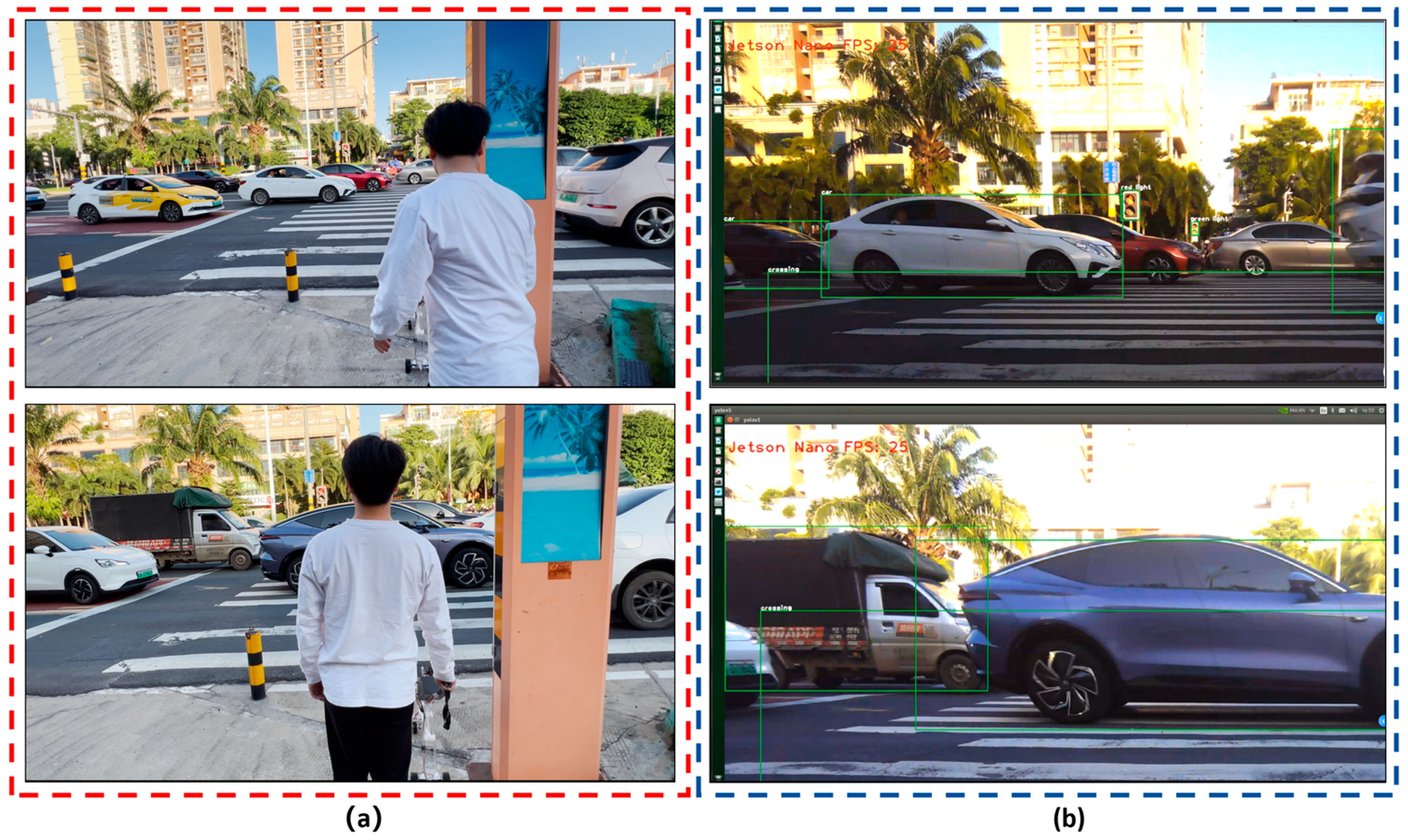
Finally, we attached an ORBBEC Gemini RGB-D camera to the Jetson nano B01, and mounted the guide system on the smart cane. We carried the smart cane to the entrance of the library of Hainan Normal University and carried out field tests on several sections of Longkun South Road in Haikou City, Hainan Province, to simulate the process of visually impaired people identifying obstacles in front of them during walking. The tests of improved yolov5 obstacle recognition on campus and on the road are shown in Figures 14 and 15.
Figure 14.
Improved yolov5 obstacle recognition for field tests on campus: (a) Field test map on campus; (b)The improved yolov5 obstacle recognition can identify objects such as pedestrians, motorcycles, and cars.
Figure 14.
Improved yolov5 obstacle recognition for field tests on campus: (a) Field test map on campus; (b)The improved yolov5 obstacle recognition can identify objects such as pedestrians, motorcycles, and cars.
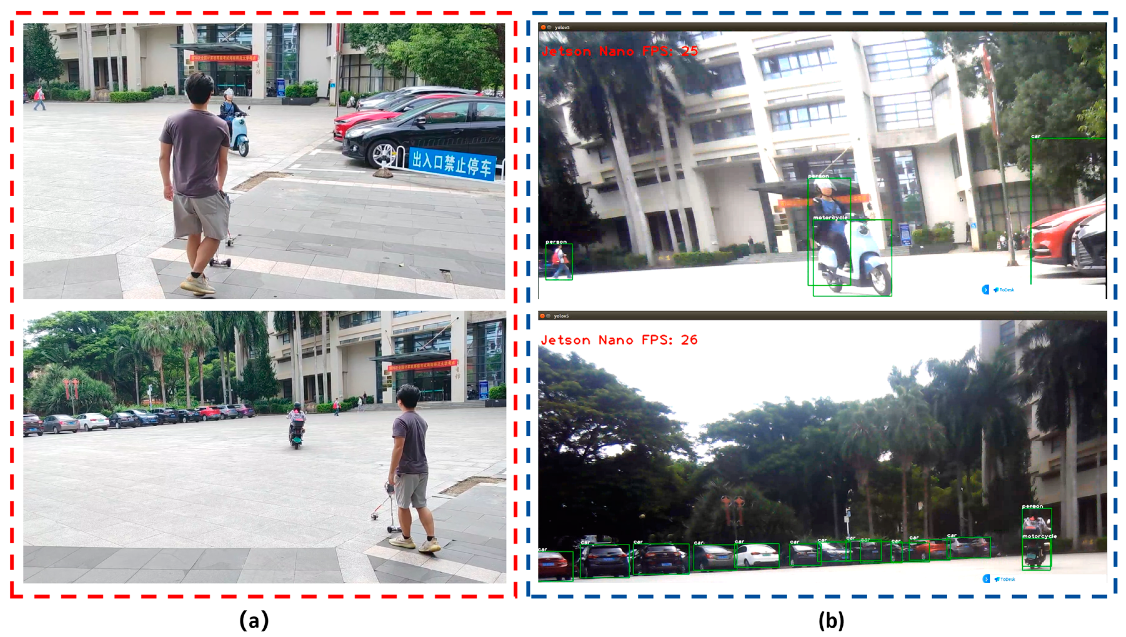
Figure 15.
Field testing of improved yolov5 obstacle recognition on the road: (a) Field test on the road; (b)Improved yolov5 obstacle recognition, which can recognize objects such as cars, trucks, pedestrian crossings, traffic lights (red light and green light).
Figure 15.
Field testing of improved yolov5 obstacle recognition on the road: (a) Field test on the road; (b)Improved yolov5 obstacle recognition, which can recognize objects such as cars, trucks, pedestrian crossings, traffic lights (red light and green light).
The test results show that: (1) The intelligent guide system developed by us can effectively identify the objects in front of the visually impaired person, such as pedestrians, cars, motorcycles, trucks, pedestrian crossings, traffic lights, etc. The recognition rate of the intelligent guide system for pedestrian crossing is 84.6%, the recognition rate of the system for vehicles is more than 71.8%, and the overall recognition rate of the system for 86 types of objects is 61.2%; (2) The number of frames transmitted per second for target recognition is 25 to 26FPS, so the visually impaired can completely identify obstacles in real time without much error. (3) In the field test process, under following conditions, a) with interference of strong sunlight during the day, as shown in Figure 16, or b) without enough light in the surroundings at night, as shown in Figure 17, or c) with cars moving too fast on the road, etc., the obstacle recognition rate will be reduced, to some degree, obstacles in front of the visually impaired can still be identified.
5. Discussion
Compared with many other intelligent guide systems, the main advantage of the intelligent guide system proposed in this work is that the distance between the smart cane and the obstacle can be measured by two-dimensional LiDAR to achieve laser SLAM, and at the same time, it can identify obstacles in front of the visually impaired person, improve the real-time response speed of the intelligent guide system, increase the types of obstacle recognition and expand the overall detection range. The experiment simulated the process of the visually impaired person leaving the tactile paving to the pedestrian crossing, waiting for the traffic light and avoiding obstacles, and walking on the campus road. The smart cane does not need to lay new Tactile Paving indoors and outdoors and specific electronic position information transceiver devices, and can actively provide direction guidance for the visually impaired in unfamiliar environments, avoid obstacles in front of him, guide him to the destination, and provide safety and convenience for the visually impaired.
5.1. The choice of main control module of smart cane
The laser and vision sensing smart cane system originally used the smaller Raspberry PI 4B as the main control module, but the research and development process summary found that the Raspberry PI 4B has a slow response speed and weak real-time processing ability. Because Raspberry PI 4B lacks a complete GPU and therefore lacks deep learning capability, there is relatively a large delay when using Raspberry PI 4B for yolov5 target recognition.
We made some efforts to improve the recognition rate of the Raspberry PI 4B, the improvement steps are as follows:
We used the Raspberry PI 4B as the video image transfer server. The images obtained by the RGB-D camera do not use the CPU of the Raspberry PI 4B for reasoning, but use the rented Ali Cloud-Cloud server Ubuntu20.04 (2 core CPU, 2GB memory, 60GB ESSD, 5Mbps) for video image transfer. Real Time Messaging Protocol (RTMP) stream server was built using nginx server software, and ffmpeg was used to push the stream. Video image was pushed to Intel(R) Core(TM)i5-11400F. The GPU graphics card is the calculator processor of NVDIA GeForce RTX 2060 for inference recognition. Though we made such improvements, the recognition rate of the improved Raspberry PI 4B still has a delay of more than 10 seconds, and can not recognize the obstacles in front of the smart cane in real time.
Then, we compared and analyzed the obstacle recognition performance of Jetson Nano B01 and Raspberry PI 4B in this work. In the case of the same yolov5 obstacle model, the speed of object recognition of Raspberry PI 4B is only about 0.444FPS. The Jetson Nano B01 can recognize objects at up to 26FPS. It can be seen that the object recognition rate of Jetson Nano B01 in this work is much higher than that of Raspberry PI 4B, and the recognition rate of Jetson Nano B01 is about 58.6 times that of Raspberry PI 4B. The comparative analysis of object recognition rates is shown in Figure 18. Because Jetson Nano B01 has a complete GPU and has a fast response speed, Jetson Nona B01 is superior to Raspberry PI 4B in this work due to its data processing, image acquisition, recognition rate and other performance. Therefore, we chose Jetson Nona B01(4GB) with deep learning capability as the main control module of the smart cane.
5.2. Limitations of this work
There are some limitations in this work, and more efforts should be made to improve. The laser SLAM mentioned in this work uses two-dimensional lidar, so the guide system can only obtain the obstacle distance information of the same height as the two-dimensional LiDAR on the smart cane. Such distance information can only know the local distance information of the obstacles in front of the visually impaired person, but cannot obtain the overall distance information of the obstacles in front of the visually impaired person. As a result, there are obstacles that cannot be measured at a lower height and obstacles that are suspended in mid-air. Therefore, as the next step, we plan to replace the 2D LiDAR with the 3D 16-wire TOF LiDAR, to obtain the 3D distance information of obstacles, and install ultrasonic modules on the bottom and top of the smart cane to measure the distance of obstacles that are low in front of the smart cane or suspended in mid-air.
6. Conclusions
We proposed an intelligent guide system based on 2D LiDAR and RGB-D camera sensing, and designed the appearance structure of the smart cane, and installed the developed intelligent guide system on the smart cane. The guide system on the smart cane uses two-dimensional Lidar, depth camera, IMU, GPS, Jetson nano, STM32 and other hardware to build a two-dimensional map of the visually impaired person's surroundings and plan the navigation path based on Cartographer algorithm,and using the improved yolov5 algorithm to quickly and effectively identify the common obstacles on the road surface. The experimental results show that the system can achieve 25-31FPS laser SLAM, and can achieve short-distance obstacle avoidance navigation in indoor and outdoor areas. It can effectively identify obstacles such as pedestrians, vehicles, tactile paving, pedestrian crossings, traffic lights (red light state, green light state), warning columns, and stone piers on the highway. The intelligent guide system can recognize 86 types of objects, among which, the recognition rate of the system is 84.6% for pedestrian crossing and more than 71.8% for vehicles. The overall recognition rate of the system is 61.2% for 86 types of objects, and the recognition rate of the intelligent guide system is 25~26FPS. In summary, the intelligent guide system developed by us can effectively guide the visually impaired to the predicted destination, and can quickly and effectively identify the obstacles on the way out.
Author Contributions
Data curation, L.Z. and Y.Q.; Investigation, H.C., and Z.L.; Methodology, Z.Q.and L.L.(Lianhe Li); Validation, G.L.; Writing—original draft, C.M.; Writing—review & editing, L.L.(Lin Li)All authors have read and agreed to the published version of the manuscript.
Funding
This research was funded by Hainan Provincial Natural Science Foundation of China, grant number123MS035, Finance science and technology project of Hainan province, grant number ZDYF2020217, National Natural Science Foundation of China, grant number 62064004, 62174046 and 62274048, specific research fund of The Innovation Platform for Academicians of Hainan Province, grant number YSPTZX202127.
Data Availability Statement
The authors declare no conflict of interest.
Acknowledgments
The authors declare no conflict of interest.
Conflicts of Interest
The authors declare no conflict of interest.
References
- Ackland, P.; Resnikoff, S.; Bourne, R. World blindness and visual impairment: despite many successes, the problem is growing. Community eye health 2017, 30, 71–73. [Google Scholar]
- World Health Organization. World report on vision. Available online: https://www.who.int/zh/news-room/detail/08-10-2019-who-launches-first-world-report-on-vision (accessed on 24 November 2022).
- Bourne, R.; Steinmetz, J.D.; Flaxman, S.; Briant, P.S.; Taylor, H.R.; Resnikoff, S.; Tareque, M.I. Trends in prevalence of blindness and distance and near vision impairment over 30 years: an analysis for the Global Burden of Disease Study. The Lancet global health 2021, 9, 130–143. [Google Scholar] [CrossRef]
- Mai, C.; Xie, D.; Zeng, L.; Li, Z.; Li, Z.; Qiao, Z.; Qu, Y.; Liu, G.; Li, L. Laser Sensing and Vision Sensing Smart Blind Cane: A Review. Sensors 2013, 23, 869. [Google Scholar] [CrossRef]
- Jain, M.; Patel, W. Review on LiDAR-Based Navigation Systems for the Visually Impaired. SN Computer Science 2023, 4, 323. [Google Scholar] [CrossRef]
- Bamdad, M.; Scaramuzza, D.; Darvishy, A. SLAM for Visually Impaired Navigation: A Systematic Literature Review of the Current State of Research. arXiv 2023, arXiv:2212.04745v2. [Google Scholar]
- Plikynas, D.; Žvironas, A.; Budrionis, A.; Gudauskis, M. Indoor navigation systems for visually impaired persons: Mapping the features of existing technologies to user needs. Sensors 2020, 20, 636. [Google Scholar] [CrossRef]
- Bhandari, A.; Prasad, P.W.C.; Alsadoon, A.; Maag, A. Object detection and recognition: using deep learning to assist the visually impaired. Disability and Rehabilitation: Assistive Technology 2021, 16, 280–288. [Google Scholar] [CrossRef]
- Chen, H.; Li, X.; Zhang, Z.; Zhao, R. Research Advanced in Blind Navigation based on YOLO SLAM. Proceedings of the 2nd International Conference on Computational Innovation and Applied Physics 2023, 163-171.
- Simões, W.C.; Machado, G.S.; Sales, A.M.; de Lucena, M.M.; Jazdi, N.; de Lucena Jr, V.F. A review of technologies and techniques for indoor navigation systems for the visually impaired. Sensors 2020, 20, 3935. [Google Scholar] [CrossRef]
- Prasad, N.; Nadaf, A.; Patel, M. A Literature Survey on Vision Assistance System Based on Binocular Sensors for Visually Impaired Users. Journal of Artificial Intelligence, Machine Learning and Neural Network 2022, 2, 33–42. [Google Scholar] [CrossRef]
- Kandalan, R.N.; Namuduri, K. Techniques for constructing indoor navigation systems for the visually impaired: A review. IEEE Transactions on Human-Machine Systems 2020, 50, 492–506. [Google Scholar] [CrossRef]
- Slade, P.; Tambe, A.; Kochenderfer, M.J. Multimodal sensing and intuitive steering assistance improve navigation and mobility for people with impaired vision. Sci. Robot. 2021, 6, eabg6594. [Google Scholar] [CrossRef] [PubMed]
- Carranza, A.; Baez, A.; Hernandez, J.; Carranza, H.; Rahemi, H. Raspberry Pi and White Cane Integration for Assisting the Visually Impaired. In Proceedings of the the 9th International Conference of Control Systems, and Robotics (CDSR’22), Niagara Falls, NA, Canada, 2–4 June 2022.
- Chuang, T.K.; Lin, N.C.; Chen, J.S.; Hung, C.H.; Huang, Y.W.; Teng, C.; Huang, H.; Yu, L.F.; Giarré, L.; Wang, H.C. Deep trail-following robotic guide dog in pedestrian environments for people who are blind and visually impaired-learning from virtual and real worlds. In Proceedings of the 2018 IEEE International Conference on Robotics and Automation (ICRA), Brisbane, QLD, Australia, 21–25 May 2018.
- Jin, Y.; Kim, J.; Kim, B.; Mallipeddi, R.; Lee, M. Smart cane: Face recognition system for blind. In Proceedings of the 3rd International Conference on Human-Agent Interaction, Daegu, Republic of Korea, 21–24 October 2015.
- Jivrajani, K.; Patel, S.K.; Parmar, C.; Surve, J.; Ahmed, K.; Bui, F.M.; Al-Zahrani, F.A. AIoT-based smart stick for visually impaired person. IEEE Transactions on Instrumentation and Measurement 2022, 72, 1–11. [Google Scholar] [CrossRef]
- Hakim, H.; Fadhil, A. Indoor Low Cost Assistive Device using 2D SLAM Based on LiDAR for Visually Impaired People. Iraqi Journal for Electrical & Electronic Engineering 2019, 15. [Google Scholar]
- Hakim, H.; Alhakeem, Z.M.; Fadhil, A. Asus Xtion Pro Camera Performance in Constructing a 2D Map Using Hector SLAM Method. Iraqi Journal of Communication, Control & Engineering 2021, 21, 1–11. [Google Scholar]
- Kumar, B. ViT Cane: Visual Assistant for the Visually Impaired. arXiv 2021, arXiv:2109.13857. [Google Scholar]
- Kumar, N.; Jain, A. A Deep Learning Based Model to Assist Blind People in Their Navigation. Journal of Information Technology Education: Innovations in Practice 2022, 21, 095–114. [Google Scholar] [CrossRef] [PubMed]
- Xie, Z.; Li, Z.; Zhang, Y.; Zhang, J.; Liu, F.; Chen, W. A multi-sensory guidance system for the visually impaired using YOLO and ORB-SLAM. Information 2022, 13, 343. [Google Scholar] [CrossRef]
- Udayagini, L.; Vanga, S.R.; Kukkala, L.; Remalli, K.K.; Lolabhattu, S.S. Smart Cane For Blind People. In 2023 10th International Conference on Signal Processing and Integrated Networks (SPIN), Noida, India, 23-24 March 2023.
- Ye, C.; Hong, S.; Qian, X. A co-robotic cane for blind navigation. In Proceedings of the 2014 IEEE International Conference on Systems, Man, and Cybernetics (SMC), San Diego, CA, USA, 5–8 October 2014.
- Agrawal, S.; West, M.E.; Hayes, B. A Novel Perceptive Robotic Cane with Haptic Navigation for Enabling Vision-Independent Participation in the Social Dynamics of Seat Choice. In Proceedings of the IEEERSJ International Conference on Intelligent Robots and Systems, Prague, Czech Republic, 27 September–1 October 2021.
- Zhang, H.; Ye, C. An indoor wayfinding system based on geometric features aided graph SLAM for the visually impaired. IEEE Trans. Neural Syst. Rehabil. Eng. 2017, 25, 1592–1604. [Google Scholar] [CrossRef] [PubMed]
- Ye, C.; Qian, X. 3-D object recognition of a robotic navigation aid for the visually impaired. IEEE Transactions on Neural Systems and Rehabilitation Engineering 2018, 26, 441–450. [Google Scholar] [CrossRef] [PubMed]
- Zhang, H.; Jin, L.; Zhang, H.; Ye, C. A comparative analysis of visual-inertial slam for assisted wayfinding of the visually impaired. In 2019 IEEE Winter Conference on Applications of Computer Vision (WACV), Waikoloa, HI, USA, 07-11 January 2019.
- Ju, J.S.; Ko, E.; Kim, E.Y. EYECane: Navigating with camera embedded white cane for visually impaired person. In Proceedings of the 11th international ACM SIGACCESS conference on Computers and accessibility, pp. 237–238.
- Masud, U.; Saeed, T.; Malaikah, H.M.; Islam, F.U.; Abbas, G. Smart assistive system for visually impaired people obstruction avoidance through object detection and classification. IEEE Access 2022, 10, 13428–13441. [Google Scholar] [CrossRef]
- Suresh, K. Smart Assistive Stick for Visually Impaired Person with Image Recognition. In 2022 International Conference on Power, Energy, Control and Transmission Systems (ICPECTS), Chennai, India, 08-09 December 2022.
- Chen, Q.; Khan, M.; Tsangouri, C.; Yang, C.; Li, B.; Xiao, J.; Zhu, Z. CCNY smart cane. In Proceedings of the 2017 IEEE 7th Annual International Conference on CYBER Technology in Automation, Control, and Intelligent Systems (CYBER), Honolulu, HI, USA, 31 July–4 August 2017.
- Jin, L.; Zhang, H.; Ye, C. Camera intrinsic parameters estimation by visual–inertial odometry for a mobile phone with application to assisted navigation. IEEE/ASME Transactions on Mechatronics 2020, 25, 1803–1811. [Google Scholar] [CrossRef]
- Alcantarilla, P.F.; Yebes, J.J.; Almazán, J.; Bergasa, L.M. On combining visual SLAM and dense scene flow to increase the robustness of localization and mapping in dynamic environments. In Proceedings of the 2012 IEEE International Conference on Robotics and Automation, Saint Paul, MN, USA, 14–18 May 2012.
- Rodríguez, A.; Bergasa, L.M.; Alcantarilla, P.F.; Yebes, J.; Cela, A. Obstacle avoidance system for assisting visually impaired people. In Proceedings of the IEEE Intelligent Vehicles Symposium Workshops 2012, 35, 16.
- Takizawa, H.; Yamaguchi, S.; Aoyagi, M.; Ezaki, N.; Mizuno, S. Kinect cane: An assistive system for the visually impaired based on the concept of object recognition aid. Pers. Ubiquitous Comput. 2015, 19, 955–965. [Google Scholar] [CrossRef]
- Taylor, E.J. An Obstacle Avoidance System for the Visually Impaired Using 3-D Point Cloud Processing. Master’s Thesis, Brigham Young University, Provo, UT, USA, 2017.
- Ranganeni, V.; Sinclair, M.; Ofek, E.; Miller, A.; Campbell, J.; Kolobov, A.; Cutrell, E. Exploring Levels of Control for a Navigation Assistant for Blind Travelers. In Proceedings of the 2023 ACM/IEEE International Conference on Human-Robot Interaction 2023, pp. 4–12.
- Achuth Ram, M.; Shaji, I.; Alappatt, I.B.; Varghese, J.; John Paul, C.D.; Thomas, M.J. Easy Portability and Cost-Effective Assistive Mechanism for the Visually Impaired. ICT Infrastructure and Computing 2022, pp. 491–498.
- Lu, C.L.; Liu, Z.Y.; Huang, J.T.; Huang, C.I.; Wang, B.H.; Chen, Y.; Kuo, P.Y. Assistive navigation using deep reinforcement learning guiding robot with UWB/voice beacons and semantic feedbacks for blind and visually impaired people. Frontiers in Robotics and AI 2021, 8, 654132. [Google Scholar] [CrossRef] [PubMed]
- Chaudhari, G.; Deshpande, A. Robotic assistant for visually impaired using sensor fusion. In 2017 IEEE SmartWorld, Ubiquitous Intelligence & Computing, Advanced & Trusted Computed, Scalable Computing & Communications, Cloud & Big Data Computing, Internet of People and Smart City Innovation (SmartWorld/SCALCOM/UIC/ATC/CBDCom/IOP/SCI), Francisco, CA, USA, 04-08 August 2017.
- Wu, Y.; Hao, L.; Wang, F.; Zu, L. The Construction of Occupancy Grid Map with Semantic Information for the Indoor Blind Guiding Robot. In 2023 IEEE 13th International Conference on CYBER Technology in Automation, Control, and Intelligent Systems (CYBER), Qinhuangdao, China, 11-14 July 2023.
- Filipenko, M.; Afanasyev, I. Comparison of various slam systems for mobile robot in an indoor environment. In 2018 International Conference on Intelligent Systems (IS), Stockholm, Sweden, 16-21 May 2016.
- Hess, W.; Kohler, D.; Rapp, H.; Andor, D. Real-time loop closure in 2D LIDAR SLAM. In 2016 IEEE international conference on robotics and automation (ICRA), Stockholm, Sweden, 16-21 May 2016.
- Redmon, J.; Divvala, S.; Girshick, R.; Farhadi, A. You only look once: Unified, real-time object detection. In Proceedings of the IEEE conference on computer vision and pattern recognition 2016, pp. 779–788.
- Redmon, J.; Farhadi, A. Yolov3: An incremental improvement. arXiv 2018, arXiv:1804.02767. [Google Scholar]
- Bochkovskiy, A.; Wang, C.Y.; Liao, H.Y.M. Yolov4: Optimal speed and accuracy of object detection. arXiv 2020, arXiv:2004.10934. [Google Scholar]
- Ultralytics YOLOv5. Available online: https://github.com/ultralytics/yolov5/tree/v6.0(accessed on 13 November 2023).
- Chandna, S.; Singhal, A. Towards outdoor navigation system for visually impaired people using YOLOv5. 2022 12th International Conference on Cloud Computing, Data Science & Engineering (Confluence), Noida, India, 27-28 january 2022.
- Tai, K.W.; Lee, H.; Chen, H.H.; Yeh, J.S.; Ouhyoung, M. Guardian Angel: A Novel Walking Aid for the Visually Impaired. arXiv 2022, arXiv:2206.09570. [Google Scholar]
- Zhang, L.; Jia, K.; Liu, J.; Wang, G.; Huang, W. Design of Blind Guiding Robot Based on Speed Adaptation and Visual Recognition. IEEE Access 2023, 11, 75971–75978. [Google Scholar] [CrossRef]
- Arifando, R.; Eto, S.; Wada, C. Improved YOLOv5-Based Lightweight Object Detection Algorithm for People with Visual Impairment to Detect Buses. Applied Sciences 2023, 13, 5802. [Google Scholar] [CrossRef]
- Kumar, N.; Jain, A. A Deep Learning Based Model to Assist Blind People in Their Navigation. Journal of Information Technology Education: Innovations in Practice 2022, 21, 095–114. [Google Scholar] [CrossRef]
- Rocha, D.; Pinto, L.; Machado, J.; Soares, F.; Carvalho, V. Using Object Detection Technology to Identify Defects in Clothing for Blind People. Sensors 2023, 23, 4381. [Google Scholar] [CrossRef]
- Hsieh, I.H.; Cheng, H.C.; Ke, H.H.; Chen, H.C.; Wang, W.J. A CNN-based wearable assistive system for visually impaired people walking outdoors. Applied Sciences 2021, 11, 10026. [Google Scholar] [CrossRef]
- Sethuraman, S.C.; Tadkapally, G.R.; Mohanty, S.P.; Galada, G.; Subramanian, A. MagicEye: An Intelligent Wearable Towards Independent Living of Visually Impaired. arXiv 2023, arXiv:2303.13863. [Google Scholar]
- Abdusalomov, A.B.; Mukhiddinov, M.; Kutlimuratov, A.; Whangbo, T.K. Improved Real-Time Fire Warning System Based on Advanced Technologies for Visually Impaired People. Sensors 2022, 22, 7305. [Google Scholar] [CrossRef]
- Vaswani, A.; Shazeer, N.; Parmar, N.; Uszkoreit, J.; Jones, L.; Gomez, A.N.; Polosukhin, I. Attention is all you need. 31st Conference on Neural Information Processing Systems (NIPS 2017), Long Beach, CA, USA, 4-9 December 2017.
- Woo, S.; Park, J.; Lee, J.Y.; Kweon, I.S. Cbam: Convolutional block attention module. In Proceedings of the European conference on computer vision (ECCV) 2018, pp. 3–19.
Figure 1.
Intelligent guide system frame diagram.
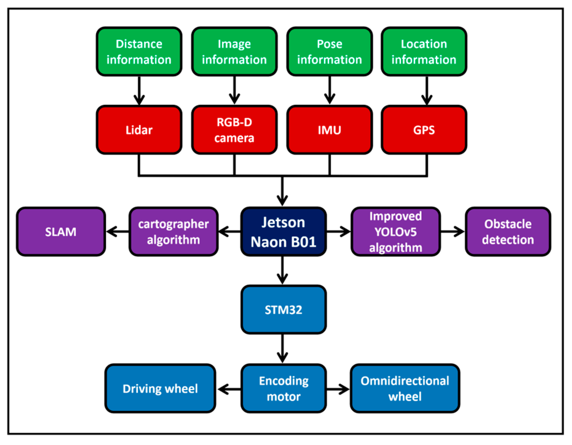
Figure 2.
Laser and vision sensing smart cane structure appearance design: (a) Smart cane 3D solid model; (b) Smart cane CAD diagram.
Figure 2.
Laser and vision sensing smart cane structure appearance design: (a) Smart cane 3D solid model; (b) Smart cane CAD diagram.
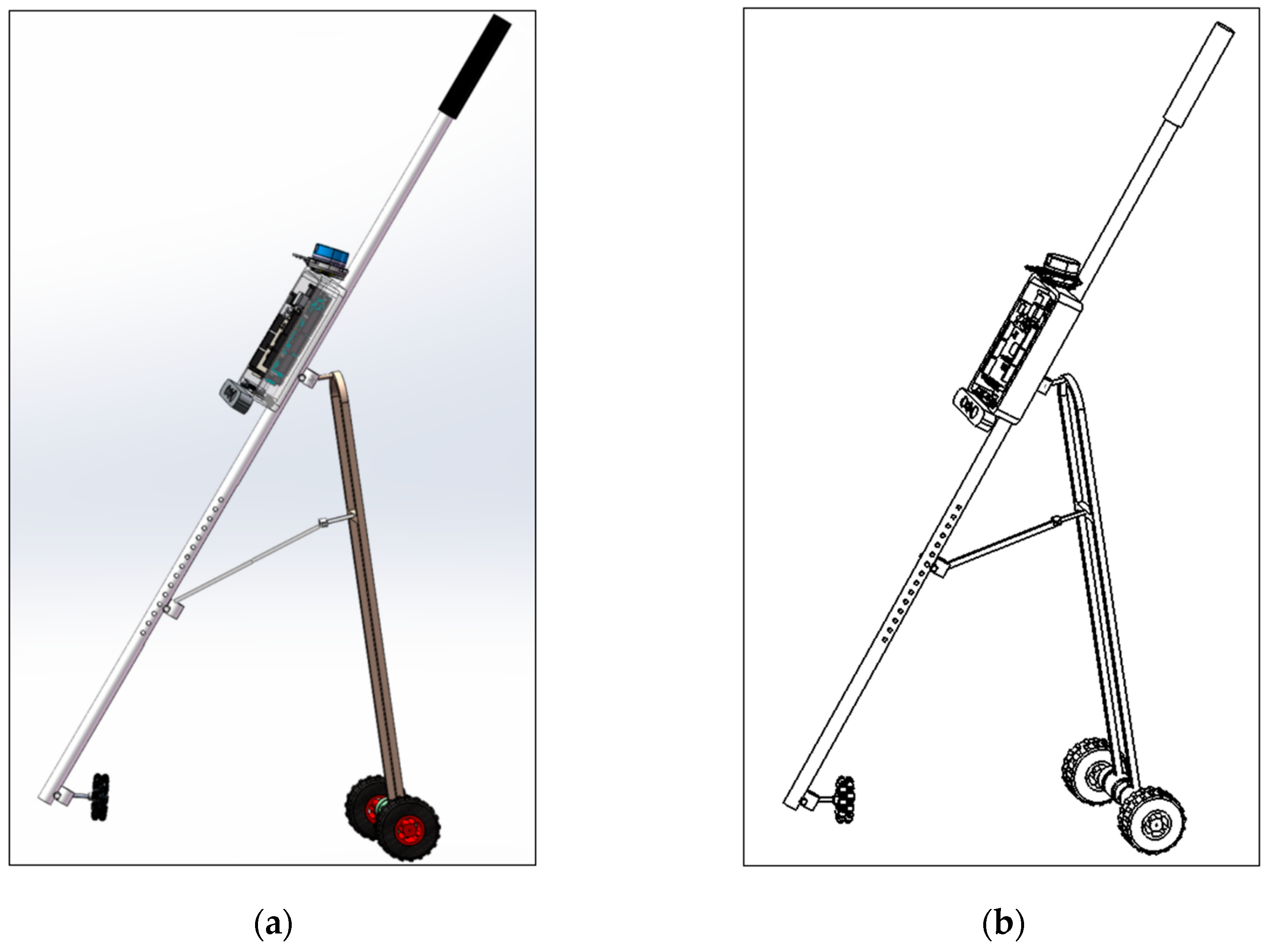
Figure 3.
The physical appearance structure of the laser and vision sensing smart cane.
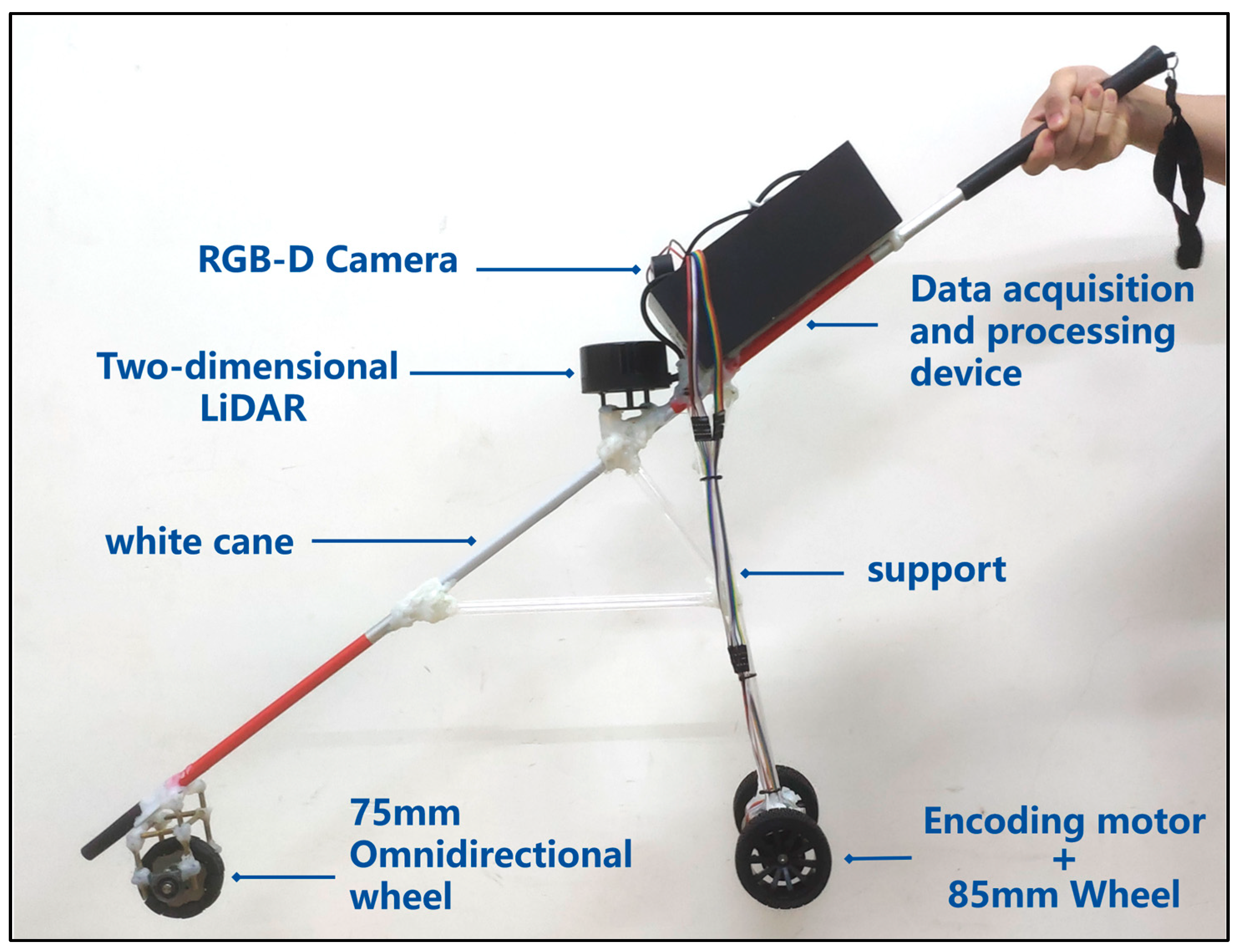
Figure 4.
Hardware structure of intelligent guide system.
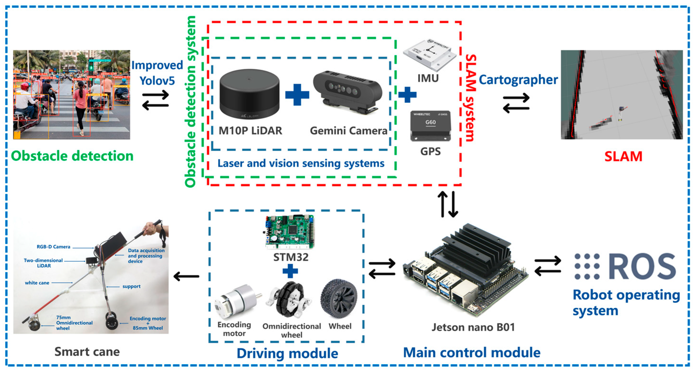
Figure 5.
Architecture of two-dimensional laser SLAM Cartographer algorithm.
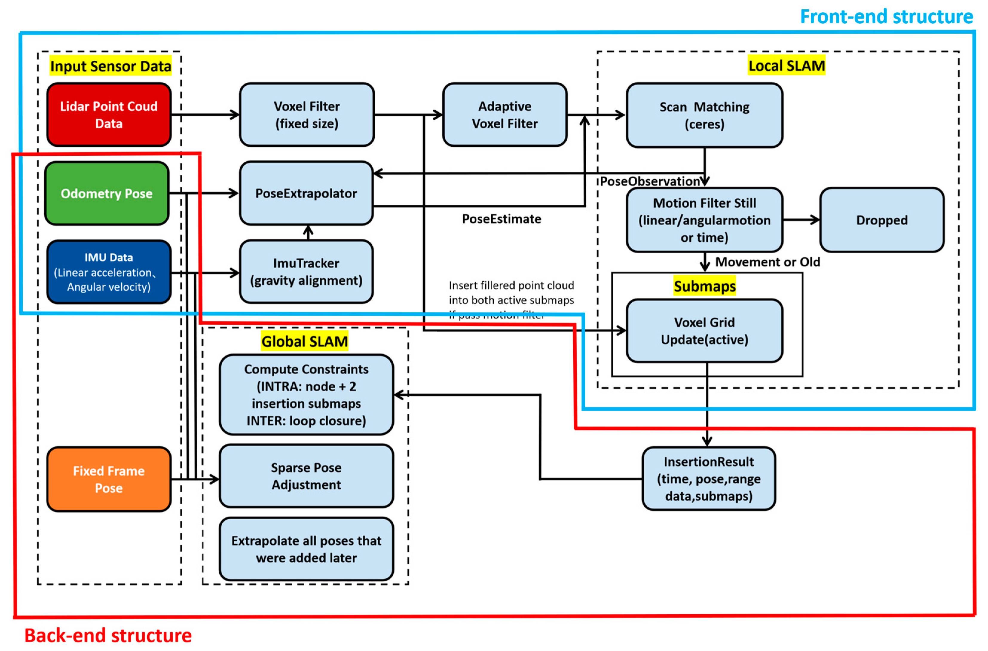
Figure 6.
Improved yolov5 algorithm architecture (C3 layer replaced with CBAM).
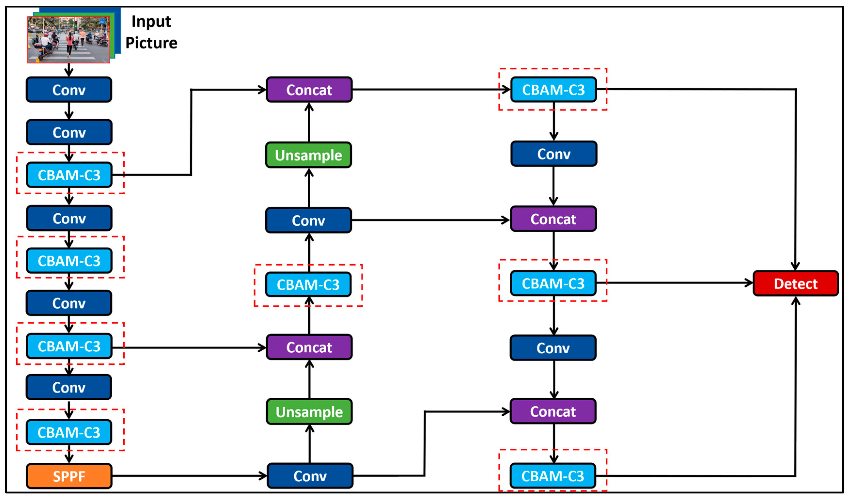
Figure 10.
The smart cane uses the Cartographer algorithm to implement laser SLAM: (a) Experimental site (Corridor and floor passages); (b) Smart cane to achieve laser SLAM.
Figure 10.
The smart cane uses the Cartographer algorithm to implement laser SLAM: (a) Experimental site (Corridor and floor passages); (b) Smart cane to achieve laser SLAM.
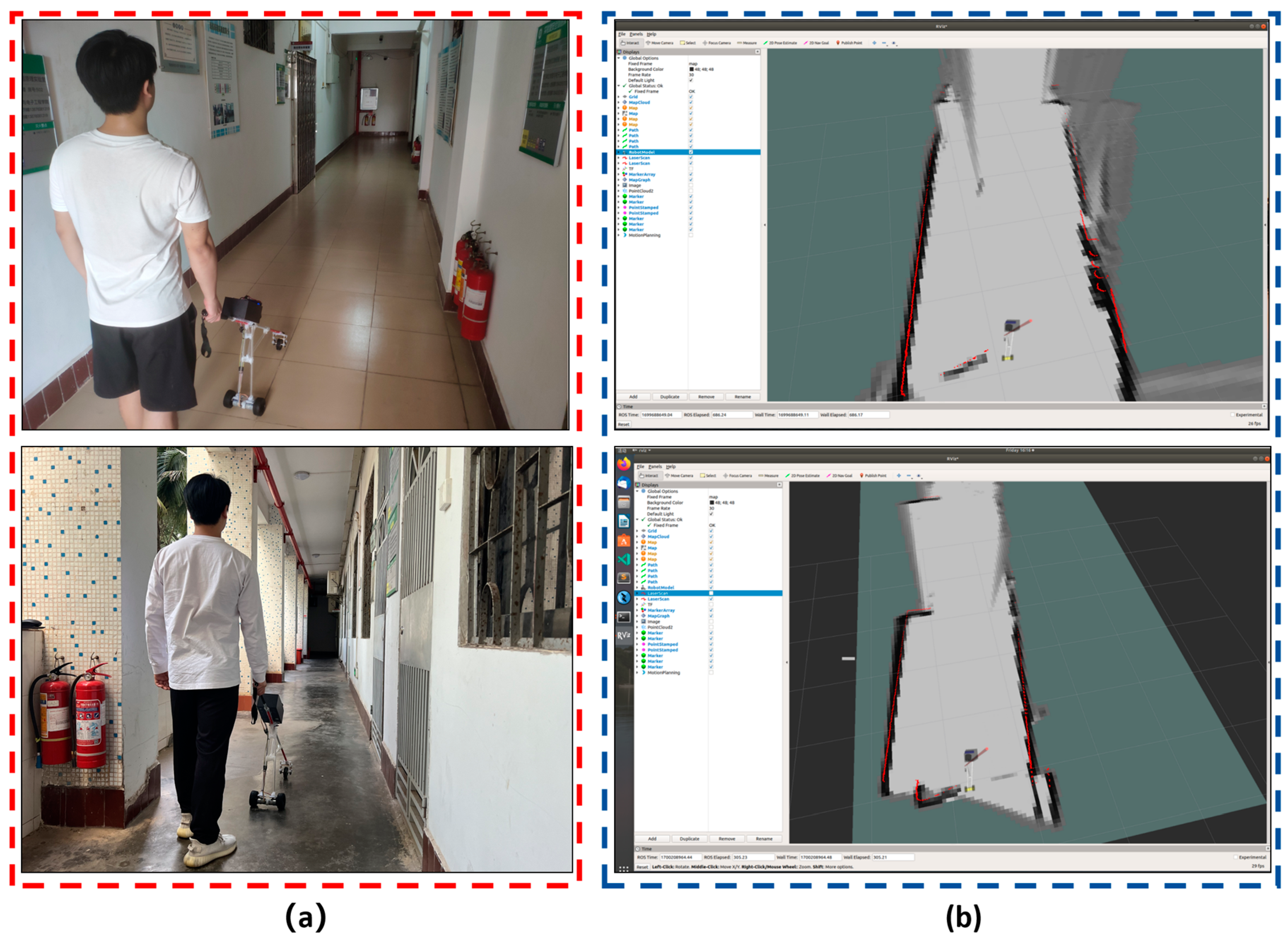
Figure 11.
Total data set of improved YOLOv5 for Intelligent Guide System (COCO 2017 Dataset + Obstacle Dataset).
Figure 11.
Total data set of improved YOLOv5 for Intelligent Guide System (COCO 2017 Dataset + Obstacle Dataset).
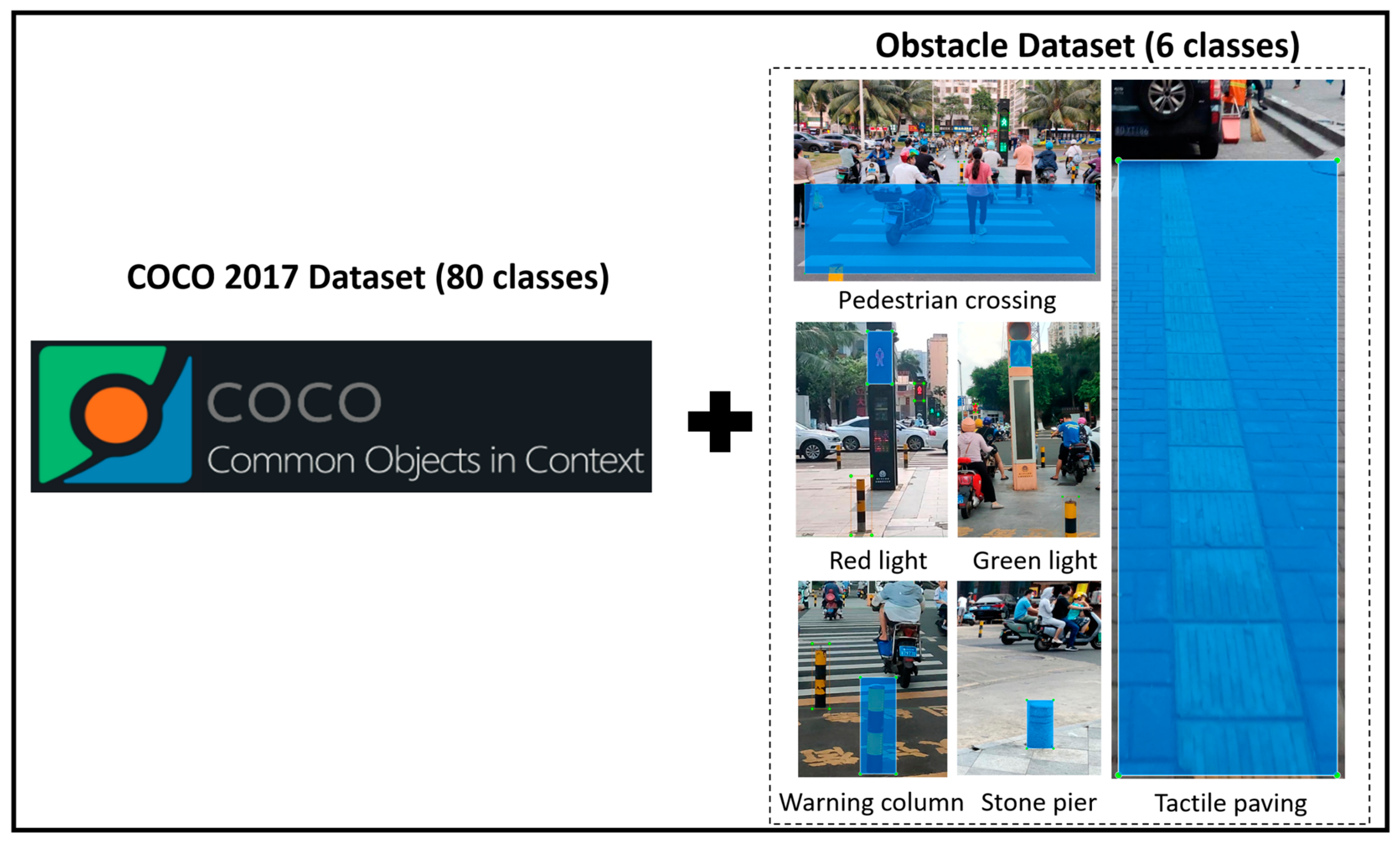
Figure 16.
In the face of strong sunlight during the day, the improved yolov5 obstacle recognition was field-tested on the road: (a) A field test on the road in the face of strong sunlight; (b)The improved yolov5 obstacle recognition can identify people, motorcycles, cars, bicycles, traffic lights and other objects.
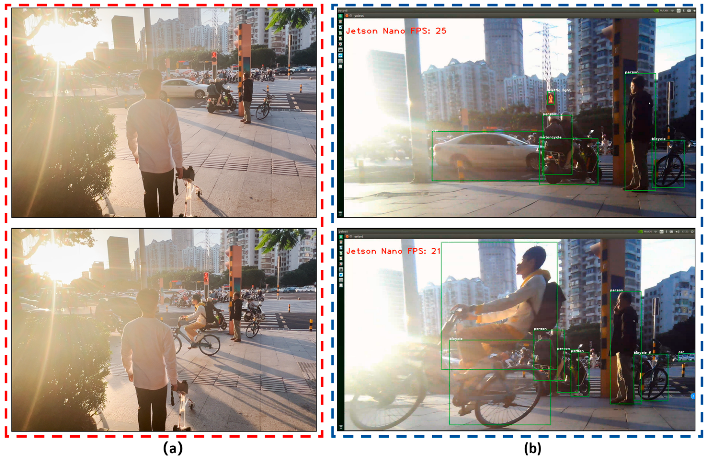
Figure 17.
Field test of improved yolov5 obstacle recognition on the road in the absence of light in the surrounding environment at night: (a) Field tests on the road at night when the surrounding environment lacks light; (b)The improved yolov5 obstacle recognition can identify objects such as people, cars, and traffic lights.
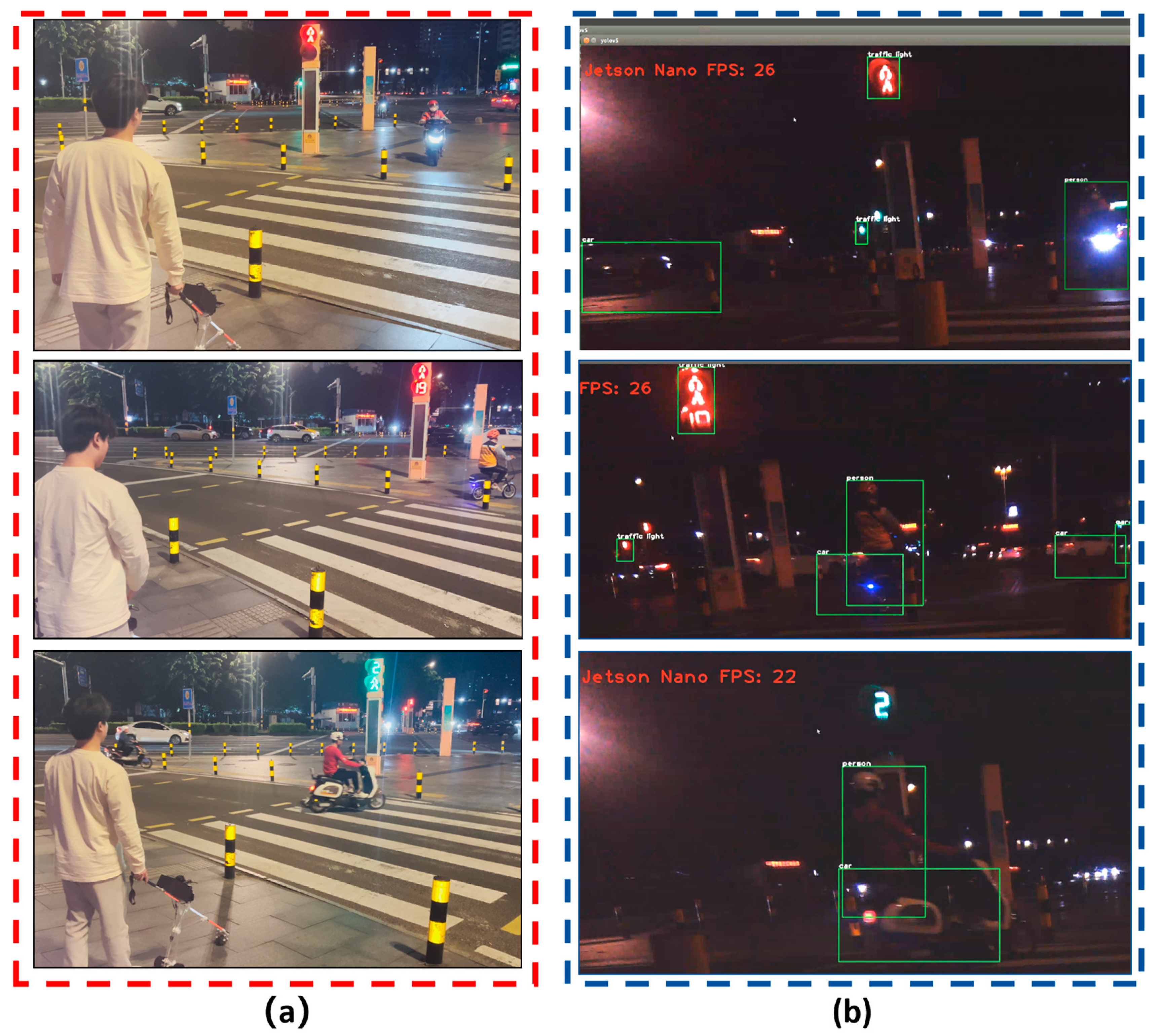
Figure 18.
Comparison of obstacle detection speed between Raspberry PI 4B and Jetson Nano B01: (a) The Raspberry PI 4B obstacle detection at approximately 0.444FPS; (b) Jetson Nano B01 obstacle detection speed: 26FPS.
Figure 18.
Comparison of obstacle detection speed between Raspberry PI 4B and Jetson Nano B01: (a) The Raspberry PI 4B obstacle detection at approximately 0.444FPS; (b) Jetson Nano B01 obstacle detection speed: 26FPS.
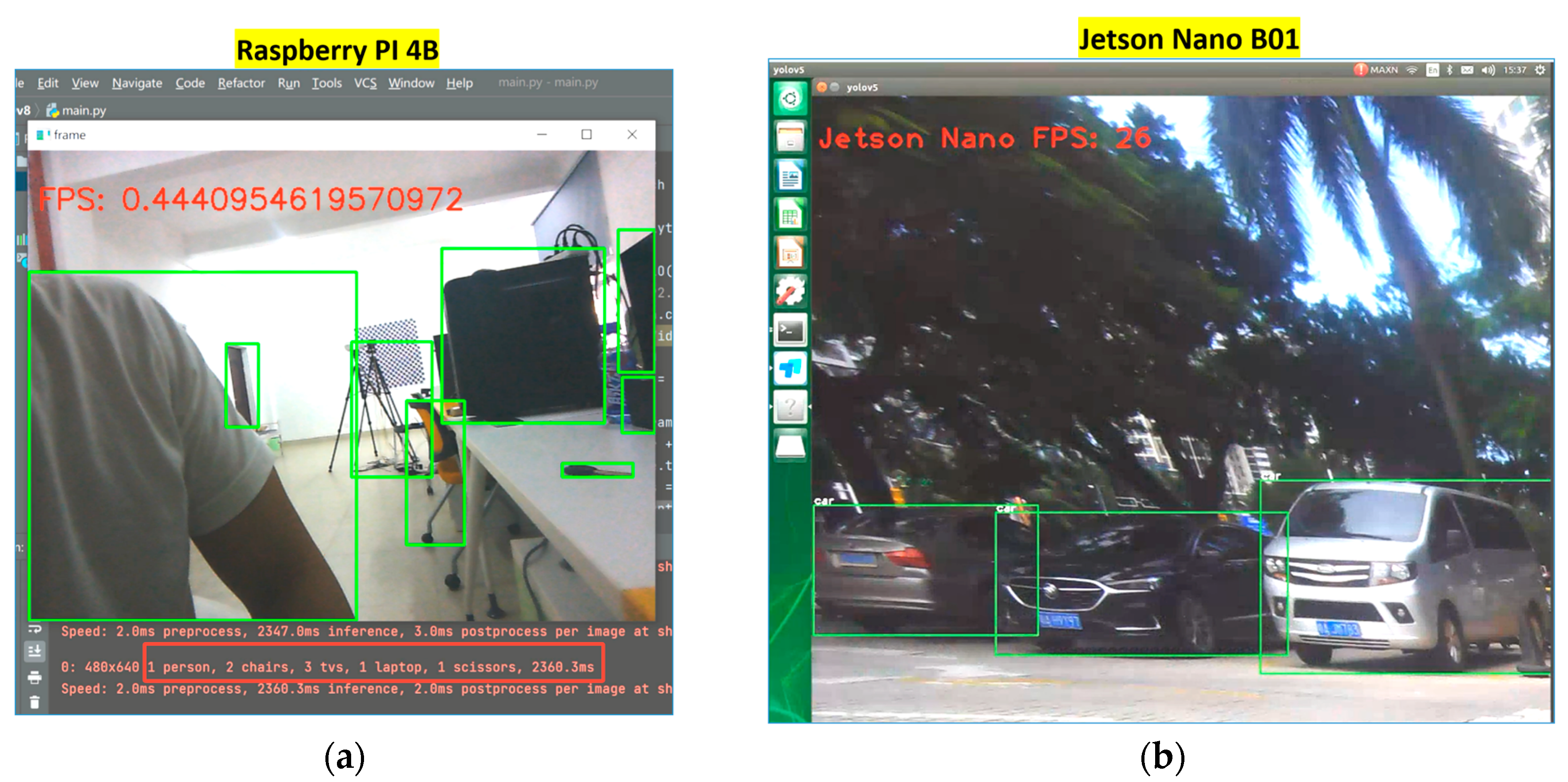
Table 3.
Jetson nano B01 system deployment environment version parameters.
| Environment | version |
| Ubunut | 18.04 |
| Python | 3.6.9 |
| Pytorch | 1.10.0 |
| Cuda | 10.2.300 |
| CuDNN | 8.2.1.8 |
| Opencv | 4.1.1 |
| TensorRT | 8.2.1 |
| Jetpack | 4.6.1 |
| Machine | aarch64 |
Disclaimer/Publisher’s Note: The statements, opinions and data contained in all publications are solely those of the individual author(s) and contributor(s) and not of MDPI and/or the editor(s). MDPI and/or the editor(s) disclaim responsibility for any injury to people or property resulting from any ideas, methods, instructions or products referred to in the content. |
© 2023 by the authors. Licensee MDPI, Basel, Switzerland. This article is an open access article distributed under the terms and conditions of the Creative Commons Attribution (CC BY) license (http://creativecommons.org/licenses/by/4.0/).
Copyright: This open access article is published under a Creative Commons CC BY 4.0 license, which permit the free download, distribution, and reuse, provided that the author and preprint are cited in any reuse.


