
Submitted:
07 September 2023
Posted:
08 September 2023
You are already at the latest version
Abstract
Integrating systems acquired from third parties and legacies has become of great necessity in companies. This is mainly due to the need to exchange information between entities, such as banks, suppliers, customers, allies, etc. Therefore, it is essential to guarantee the integrity of the data and keep the integration up to date with the changes that can occur. Furthermore, reducing the transaction risk and avoiding losing information is necessary. Implementing this complex task involving technological and business challenges requires appropriate architecture implementation. This article presents an architecture named Dynamic Canonical Data Model through agnostic messages. The contribution involves treating the low link in integrating software units, also called the integration of loosely coupled software units. In particular, it focuses on internal data and external data integration. The proposal reduces their integration, maintenance time, and cost, maximizing their scalability and promoting reuse. To illustrate their components, a case study undertaken at the Mexican Logistics Company Paquetexpress is presented. The company has evaluated different enterprise application integration systems over 26 years to achieve a standardized integration. The article describes an architecture designed and implemented for this delivery company in a real-world case. The implementation’s source code was registered in the National Registry of Copyrights of Mexico.
Keywords:
Enterprise Application Integration
; EAI
; Loose Coupling
; External Data Coupling
; Software Architecture
; System Integration
; Legacy Systems Integration
; Software Units.
1. Introduction
Nowadays, enterprises worldwide use for their internal process and operations software applications purchased from third parties, legacy systems, in-house developed applications, or a combination. This software works in several layers on different environments (i.e., operating systems, local networks, World Wide Web, cloud, etc.). Integrating systems acquired from third parties and legacies has become a significant concern for companies. Consequently, most of the software used are heterogeneous, autonomous, and operate in a distributed environment. In this regard, diversity has been considered one of the most relentless problems since it inclines to cause interoperability complications. Specifically, rise-up problems arise regarding semantic incompatible issues when software uses distinct meanings for the same data. The integration is not easy to perform; it requires the expertise of the IT (Information Technology) department because challenges are made up of several business and technical issues, especially concerning interoperability, scalability, and maintenance [1].
Integrating systems acquired by third parties is a real problem, mainly due to the lack of information exchange between entities such as banks, suppliers, and customers, among others. Continual changes in the information systems environment have become the most critical challenge in enterprises. The applications to be integrated are usually developed by different teams that often do not focus on the integration as a relevant issue for them. This is because, given the limited capacity of the resources for a large number of applications, the deployment of the integration does not scale well and leads to operational complexity and run-time overhead. Improving this is time-consuming, and there is no guarantee that the created deployment for integrating software units will yield an efficient cost. There is a Software Engineering (SE) area known as Enterprise Application Integration (EAI) [2] dedicated to research in order to ameliorate this issue. The EAI goal is to integrate application systems with different workflow functions and to build the data exchange mechanism and application communication mechanism. Implementing EAI is a complex task involving technological and business challenges and requires appropriate EAI architecture. In compliance with this, enterprise integration is implemented using different integration tools, technologies, and methodologies. They all aim to ensure that data transformation, translation, and communication are accomplished efficiently. Therefore, improvement in integration technology, mainly concerning middle-ware, provides new forms to obtain agile and responsive business architectures. Aiming at eliminating the integration challenges, EAI is proposed as a solution. Nonetheless, assessing and introducing EAI is a complex task that calls for a systematic and homogeneous architecture with suitable criteria. Faced with this situation, the need arises for new EAI proposals to resolve the external and data loose coupling for the integration at the software unit level.
Despite the required complexity in integrating software units in the real world, there is no reference guide in the context of EAI to assist in implementing architectures for the integration. Consequently, it is essential to establish a baseline that can serve as a starting point when developing integration work to develop reliable proposals that can be applied to the real world. Furthermore, this will satisfy enterprise expectations since software units and independent software system elements are highly interconnected and represent a high information-sharing budget.
Hence, this approach presents a scalable architecture that allows a better adaptation in integrating software units (platforms, applications, and any software system that can be integrated with another) with easy maintenance. The idea is to ameliorate the reduction of cost and time in the integration through low coupling. To achieve this, a Canonical Data Model (CDM) was defined, which, according to the International Business Machines Corporation (IBM), is a well-defined model that structures the information in an organization; the objective is not only limited to modeling the data in a database but serves as a reference for all the entities and their relationships through all the databases that exist in the company and all the legacy applications that contribute to the initiative[3]. This model was extended with Agnostic Messages (AM), which are digital structures representing an unknown entity or process regardless of whether they are used at design or run-time [4]. These messages allow data to be modeled within a single database and serve as a reference for all entities and their relationships, as well as represent common information produced and consumed by applications [5] in a simplified manner using structures MAP collection (key-value structures without duplicated keys).
The direct users of this architecture, named Dynamic Canonical Data Model (DCDM), are architects and software developers in charge of analyzing, proposing, and implementing integration solutions. In this form, they will benefit by allowing an architecture that provides them the much sought-after, low coupling between technological architects when proposing integration solutions. The proposed architecture can be applied to:
- Integration from one to different software units, generating data integration between different platforms and systems.
- Maintain master data integration. Master data is all the data critical to running a business, describing people (customers, employees, and suppliers), places (offices and locations), and things (products and assets) in different repositories. From a single master data point, different platforms and systems are maintained.
- Any integration running a Data Manipulation Language (DML) of a database with its respective operations (insert, update, delete, and query). It can be used for data maintenance on different platforms and protocols at runtime.
The Dynamic Canonical Data Model architecture presented in this article was developed to satisfy the integration needs of the Mexican Logistics Company Paquetexpress 1, dedicated to national and international parcel delivery in more than 240 countries around the world. The case was developed in response to the need for integration of software units, particularly in the case of shipment validations with Amazon2 and Mercadolibre3. The DCDM architecture was designed according to the shortcomings detected in EAI in previous research presented at [1]. This was because the integration costs per year represented a high expense for the company. For this reason, a research project was developed in the Information Technology (IT) department and the Postgraduate Program in Applied Informatics at the Universidad Autónoma de Sinaloa 4, where the DCDM architecture emerged. In Mexico, the authorship of the source code was registered in the National Registry of Copyrights (Registro Nacional de Derechos de Autor, abreviated as INDAUTOR)5 since in Mexico the software as such is not subject to patent. The DCDM architecture was registered as MCDD V.1.0 with the number: 03-2023-052910244600-01 in INDAUTOR.
This article is structured as follows. Section 2 details related work about EAI. Section 3 presents an architecture proposal for the external and data loose coupling for integrating software units. Section 3.6 describes a case study. In Section 4, conclusions and some ideas for future research are presented.
2. Related Work
This section presents and analyzes the results obtained after conducting related work research focused on architectures that improve loose coupling using EAI. The most used for this purpose is SOA (Service Oriented Architecture) [6,7,8,9,10,11,12,13,14,15,16,17,18]. The integration corresponds to an orchestration of technologies supported by existing communication protocols such as SOAP (Simple Object Access Protocol), HTTP (Hypertext Transfer Protocol), among others.
A case study that explores the evolution of an established legacy system towards a more maintainable Service-Oriented Architecture (SOA) is presented in [6]. The suggested approach entails the restoration of the legacy system’s architecture as an initial phase, enabling the formulation and implementation of a targeted evolution plan. The case study focuses on a medical imaging system, demonstrating its transformation into a service-based model.
In [7], the authors focus on developing an SOA-based model for Information Technologies (IT) integration into Intelligent Transportation Systems (ITS). They applied the proposed model involving some key elements (Roadside Unit (RSU) and navigation systems) to generate value-added ITS. A case study has been designed and implemented to illustrate the application of the model to an effective ITS service (parking management system) that includes all the components of our model.
A service-oriented model for information integration is presented in [8]. The model mainly focuses on giving a complete structure for information integration that is adaptable to any environment. The information is converted into service, and then the information services are integrated through service-oriented integration to provide the information as a service.
The author in [9] proposes a new concept of SOA/ESB architecture for WSNs, called "miniSOA/ESB," to address the problem of the restricted computing power and processing capacity of the sensors node due to may not be possible for sensor data to be encoded in XML format within SOAP envelops or transported using internet protocol to applications.
In [10] combines the technology of web services and ServiceMix bus (a frame of SOA-based loose-coupling system integration) to effectively resolve the existing systems’ problems, including information delay and ineffective management of customer expectations.
The research of [11] analyzes the characteristics of SOA. It determines that it can not meet some characteristics of mission-critical applications such as high availability, continuous operation, high flexibility, high performance, etc. Also, the concept of ADS and its architecture was explored, and it was found that such requirements are satisfied by this system designing paradigm. The authors present a novel SOA-ADS modeling approach called Autonomous Decentralized Service Oriented Architecture (ADSOA); the Low Coupling Synchronization and Transactional Delivery Technology was proposed to ensure data consistency and high application availability. A prototype tested the effectiveness and feasibility of the ADSOA and proposed technology.
A combination of SOA and Web service technology that simplifies the application integration into the development and use of services, solving the connectivity of the isomerous platform, security, loose coupling between systems, and refactoring and optimizing the processes is presented in [12]. The research integrates the isomerous enterprise systems, applications, and business processes and composes the application environment of the data sources as a whole system. In addition, the technique standards, such as SOAP, WSDL, BPEL, WDDI, are studied.
The authors in [13] propose a security architecture constructed as an adaptive way-forward Internet-of-Things (IoT) friendly security solution that is comprised of three cyclic parts: learn, predict, and prevent. A novel security component named “intelligent security engine” is introduced, which learns the possible occurrences of security threats on SOA using artificial neural network learning algorithms. It predicts the potential attacks on SOA based on obtained results by the developed theoretical security model and the written algorithms as part of the security solution to prevent SOA attacks.
In [14] was presented an adaptation to the external context making use of an Enterprise Service Bus (ESB) and Complex Event Processing (CEP). In this regard, the proposed solution first leverages well-known ESB mediation patterns (e.g., transformation) to adapt services to context transparently for the final user and the service developer. Secondly, complex event processing has been used to analyze the events received from external sources to detect relevant situations for the service context. Finally, a context reasoner has been provided, which provides the transformations to be done depending on the context events.
Two approaches to increase Web services and SOA adaptability were presented in [15]. The first is based on a technical solution considering Aspect Oriented Programming (AOP) as a new design solution for Web services. The second combines Model Driven Development (MDD) and Context-Awareness to promote reusability and adaptability of Web services behavior depending on the context.
A proposal to apply the SOA paradigm to existing Enterprise Resource Planner (ERP) systems so that building, changing, and operating other information systems is faster, easier, and cheaper is presented in [16]. In order to demonstrate this proposal, a tool to integrate with SAP systems from OutSystems, an Agile development framework, has been implemented, and this tool is a proof of concept. The authors present how this integration was achieved quickly and effectively without SAP expertise.
In [17] presents a model of integration and management for mechanical functional components that comprise the robotic control system. To that end, the authors use the human neuroregulatory system as the basis for the decomposition of tasks and actions behavior and based on the SOA paradigm for designing a distributed architecture that allows the system’s viability. This proposal will ensure a total decoupling between modules by promoting reusability and features like pattern-based design. At the same time, the system is fully distributed, ensuring high flexibility, scalability, robustness, and fault tolerance.
An integration framework based on semantic web services and SOA for supply chain collaboration was present in [18], and the process of semantic Web services and automatic matching arithmetic for web services composition are discussed. An integration framework of the agile supply chain management system based on web services shows that semantic Web services have an advantage of agile composing flows in supply chain integration.
Also, the Microservices REST (REpresentational State Transfer) architecture applied in the proposals [19,20,21,22,23] emerges as the second most used architecture for this purpose. The authors in [19] present a real-world case study in order to demonstrate how scalability is positively affected by re-implementing a monolithic architecture (MA) into a microservices architecture (MSA) and also analyzed a case study based on the FX Core system, a mission critical system of Danske Bank (Denmark). The technical problem addressed and solved in this paper is identifying a repeatable migration process that can be used to convert a real-world Monolithic architecture into a Microservices architecture in the specific setting of the financial domain. In [20], the authors review the history of software architecture and the reasons that led to the diffusion of objects and services first and microservices later. Finally, open problems and future challenges are introduced. In addition, was investigated some practical issues and point out a few potential solutions focusing on microservices. The researchers in [21,22,23] focus on analyzing microservices’ core properties, highlighting their limitations and challenges concerning components. The existing literature was analyzed and provided potential directions and interesting points in this growing field of research, assisting application designers in selecting the most appropriate approach.
In addition, it should be noted that other architectures have been implemented, such as Publish/Subcribe found in [24,25], Hub and Spoke presented in [26], Camel Apache used in [27], Multi Tier Reference proposed in [28], MOM, Message Oriented Middleware described in [29], Federated Database [30], BDI, Belief Desire Intention Software Model [31], Intermediate Layer [32], SCA, Service Component Architecture [33], Grid Computing [34] and, model-driven architecture developed to deploy microservices [35], that even if they are not very used, it is elementary to mention them.
Most loose coupling software unit integration proposals are based in an environment conformed by SOA, Web Services, and Microservices. In this environment, the network nodes make their resources available to other participants in the network as independent services to which they have access in a standardized way. Most definitions identify Web Services using SOAP and WSDL in their implementation; however, it can be implemented using any service-based technology.
3. Dynamic Canonical Data Model: An Architecture Proposal for the External and Data Loose Coupling for the Integration of Software Units
This section introduces the architecture for integrating software units called Dynamic Canonical Data Model (DCDM) by means of agnostic messages. The goal is to improve the integration of loosely coupled software units. To do this, the focus is on internal and external data integration, allowing the reduction of implementation costs and maintenance costs in enterprise platform integration.
A detailed explanation is presented in the following subsections. The first subSection 3.1 explains the DCDM architecture structure. Next, subSection 3.2 describes the Agnostic Message component that implements the structure of the message to the client, subSection 3.3 details the Envelope component as part of the Composite pattern and subSection 3.4 introduces the StretegyCDDM interface that exposes the strategies to carry out the handling of the actions in the integration. SubSection 3.5 shows the functionality of DCDM architecture, and finally, in Section 3.6, a case study undertaken at the Mexican Logistics Company Paquetexpress is presented.
3.1. The DCDM Architecture Structure
The DCDM integration architecture is divided into three components: the first one is the Message with the use of the MAP data structure, the second one is the Composite pattern that is part of the message and allows encapsulating the data in a universal composite, that is, in a unique and standardized structure that does not change over time, on the other hand the third component is the Strategy pattern with which the best strategy to take for the integration is defined through the use of a Context as appropriate. The components aim to improve the low coupling.
Figure 1 shows the components of the DCDM architecture. From left to right, the first part indicates the Client, which can be any platform, software unit, system, etc. that uses the architecture. The second component called AgnosticMessage, represents the wrapper or main message where the instructions are sent to the receiver so that it knows how the message will be handled. The information represented as MAP and the Action Type action to be executed in the Entity Name entities also travels there. The third component Composite, represents the structure where the payload called Payload is configured and stored to be integrated. Finally, the Strategy component is where the strategies or algorithms are to be implemented according to the message instructions live.
3.2. The Agnostic Message Component
In integrating software units, the interaction between them is done through the exchange of information. In this regard, the DCDM defines the Agnostic Message, which represents the transactions and properties of an existing entity in a repository or database. The particularity of this message lies in the contract or universal signature that is exposed to the applications for sending standardized information within a dynamic structure that uses the MAP component for this purpose.
The graphical representation of the Agnostic Message structure is shown in Figure 2, which exposes the components that conform to the message. Firstly, Envelope, which is the object that stores the Payload sections, i.e., the payload, which in turn contains Properties Entity or Entity Properties and the Transaction section which constitutes the information represented as a MAP <key, value> which represents the information that will be used as appropriate to the management algorithm.
The message is used universally; that is, it can be used for any purpose when adding, modifying, or deleting information from any entity in any database. Moreover, it can be drawn on executing any function or procedure found in the databases using the same message or wrapper with the proposed definition. On the other hand, this design was translated in its XSD (XML Schema Definition) schema structure form to represent the contract to the client within the WSDL (Web Services Description Language). Figure 3 shows such graphical representation in the service location section called targetNamespace that can be consumed from the web address http://message.cddm.mx/ and is where the namespace is located. The sendMessage section contains all the objects that conform to the Agnostic Message. It uses the messageFacade to access the schema of each component under transactionScheme. The Payload, conformed by actionType, entityName, fields, key, value, is storage here. The request represented by sendMessage and response by sendMessageResponse of the service are publicly exposed to be used by the different software units, and the possible actions of actionType (SAVE, UPDATE, DELETE and PROCESS) are also defined.
The representation of the Agnostic Message in the service schema towards the client is a WSDL contract exposed for consumption. The message is created in an XSD file containing predefined tags for each document element. The WSDL is composed of the tags:
- types. It shows the types of data to handle and helps shape the message.
- Message. They contain the request and response where the Agnostic Message travels.
- portType or interface tag indicates the document’s operations.
- sendMessage. Corresponds to the request in the petition.
- sendMessageResponse. The document’s response according to the petition made in sendMessage.
- binding. Specifies the communication protocol used: SOAP (Simple Object Access Protocol).
An example of the Agnostic Message implementation is shown in the SoapUI tool version 5.4.0 used as an aid for the execution of tests, where the WSDL document contract is consumed. Figure 4 shows a window of the SoapUI tool used to test the web services. The structure of the message as interpreted by a human being as it contains captured information which is observed in the tags actionType, entityName, fields, key, value. In the execution section, at the top of the image is the URL (Uniform Resource Location) or endpoint where the AgnosticMessageCDDMPort web service is hosted, and from there, the test is executed.
3.3. The Composite Envelope Component
Once the Agnostic Message was defined, the Payload (tree) compound was designed and created from the Envelope component. This pattern allows building complex objects through basic array structures and recursion. The compound tree structures are created from simpler components represented as leaves of a tree that inherit functions and properties of the first primary structure and are extended to all its nodes, which helps to simplify the treatment of the objects created through a single standard interface. In this form, all objects are managed similarly to support the message sent by the client. The Envelope component is an abstract class that contains all the properties of the Entity, such as procedures and methods that were used by the Payload compound. In addition, it contains the Message (leaf) compound, which is managed in the same manner by the Strategy pattern.
Figure 5 shows the representation of the Composite pattern implemented in the Agnostic Message. This pattern is conformed by the abstract class Envelope and has two properties. The first one is the typeNode, which indicates whether it is a tree structure or a leaf of that structure. The second one is Transaction, which is constituted by actionTye that designates the action or transaction that will be executed in the entity; in this case, it can be SAVE, UPDATE, DELETE and PROCESS. In this sense, if the value of actionType is SAVE, then a new record will be added in the entity entityName. In this order of ideas, the entityName property represents the name of the entity to be affected, and it also contains a set of instances called Fields employing the MAP object that stores the field-value records that will be added, deleted, updated or consulted of a given entity. This component has the Payload class that represents the helpful content of the message. The function of this class is to generate a structure of transactions that may affect one or several entities. In addition, it contains six methods that can be used to manage the structure, one of them is addEnvelope. As an input parameter, it receives an Envelope type object, which is used to add a node or leaf to the tree with its properties. The removeEvelope method removes or deletes a leaf (node) from the tree, and getEnvelope retrieves a leaf or set of leaves. Finally, the invokeStrategy method is the most important because it helps to invoke the Strategy component utilizing the Context that creates access to all the algorithms that will be used for the processing of the messages sent by the clients.
3.4. The StretegyCDDM Component
A fundamental component in the architecture proposed in this article is the Strategy pattern (StrategyCDDM), which consists of an interface to the clients that use the algorithms designed for the management of the Agnostic Message. This pattern is used through a context represented by the Context element as an interface to the Composite Payload client.
The algorithms created for this solution StrategyDML and StrategyProcess represent an example of the diversity of algorithms that can be defined and implemented as a strategy in each integration. This will allow the architecture to make decisions according to the incoming message.
Components were also created to access the database metadata as part of StrategyCDDM, to create the entities dynamically according to the incoming message and generate the resource for its persistence. In this sense, another method was defined to implement the persistence of the message according to the entity examined, represented, and persisted in the data stores. This concludes to implement and manage Agnostic Message messages represented in the Composite pattern.
Figure 6 shows where the Strategy pattern is implemented in the architecture proposed in this article. Moreover, it describes the classes that compose and implement the Strategy pattern, one of them is the StrategyCDDM interface that declares the manageEnvelope method. The class is implemented in the different algorithms, in this case StragyDML and StrategyProcess. In the case of the first one, it adds the methods generateEntity, executeProcess, createQueryInsert, and formatField as private and auxiliary methods. Both are responsible for creating and validating the DML (Data Manipulation Language) instruction, to be later executed with the executeProcess method. On the other hand, the StragyProcess algorithm does not have any strategy at this time, and it was created in order to later build the execution of queries and execution of store procedures and/or pl-sql depending on the database engine where it is implemented. The clients can access the algorithms using the Context class, whose function is to generate access to the composite component about the operation and management of the messages.
3.5. DCDM Architecture Functionality
To carry out the integration of software units employing Agnostic Message in order to improve the low coupling, the functionality of the architecture presented in this article is explained in this sub-section.
Figure 7 shows a sequence diagram where the three components that conform to the DCDM architecture communicate. The Figure shows how a client initiates the integration using the architecture proposed in this article. The process starts when the client sends a message addressed to the Agnostic Message component, carried out through the sendMessage operation. As an input parameter, a MessageFacade type object named Payload is sent, which represents the Composite of the Envelope component where the message is hosted. The Composite Payload message is divided into two essential parts; the first one is the Properties Entity and Transaction Entity section as shown in Figure 2. The first section of the message contains the entity’s name to be searched in the metadata of the repository or database, and this will be the starting point to create the instance or the DML (Data Manipulation Language) sequence. This will allow executing the order according to the Action Type property, which indicates the action to be performed in the database repository. In the second part, the transactions are represented by a MAP data structure. These structures allow managing the fields and their respective values, which makes it possible to store them in key/value pairs, where key is the entity’s field and value is the field’s value. Once the client has sent the message, the Strategy pattern is accessed from the Payload compound with the StrategyCDDM implementation where the algorithms that will provide a solution to the message request are stored. This access is provided through an interface called Context, the strategy to be taken according to the Action Type property, where a new instance of the algorithm to be implemented is created. StrategyDML and StrategyProcess will take care of the message and provide a solution to the integration with the managementStrategy operation, which has as input parameter the composite Message. Once the entity is generated and the message persists, a response is given to the client, indicating if the execution was correct or if there is a problem.
3.6. Application Example
This section details an example of the application of the DCDM architecture in a real environment, explains how the implementation was carried out, and validates the result.
The company selected for implementing and testing the MCDD architecture was the Mexican Logistics Company Paquetexpress (https://www.paquetexpress.com.mx). This was due to the facilities granted because of the existing working relationship. Paquetexpress was founded in 1986 and has over 8,000 employees in 20 departments. The main line of business is logistics, and the core of this is the collection, documentation, shipping, and delivery of packages, mainly in Mexico and worldwide. The central administration office is located in Los Mochis, in Ahome, Sinaloa, Mexico.
In the commercial area, which is of great importance for the company, the following problem is highlighted: how to control and record the agreements and arrangements with customers (discounts, promotions, and rates) at the time they request the services mentioned above, as well as customer follow-up, sales, and executive commissions. Likewise, there was an associated problem concerning how it affects the credit portfolio and accounting of the income of each one of them. Faced with this situation, communication was established with the board of directors in general management, commercial management, administration management, operations, and IT management to propose a solution through the DCDM architecture. The issue was also discussed with the technology architects from the IT department to see the feasibility of implementing the integration architecture presented in this article to alleviate the problems encountered. Thus, approval was obtained.
As the first step, the work plan for the integration process was defined, establishing Java as the programming language to implement the DCDM architecture. This is one of the most widely used outside the academy in the business applications industry. Afterward, the definition of the software systems to be integrated was established, among which CRM Salesforce Cloud6 and financial platforms such as Oracle Cloud ERP7, as well as all the POS (Point Of Sale) that includes online documentation and web services for B2B (business to business) integration of customers. The solution to the problem of the Mexican Logistics Company Paquetexpress using the MCDD architecture, according to the integration plan, is divided into five steps, each of which is listed below:
- Creation of the Envelope, Payload and Messages components.
- Generation of the Transaction (MAP) structure.
- Generation of the Agnostic Message (MessageFacade). Loading of the Payload component with Message sheets.
- Generation of the Strategy component (StrategyCDDM) algorithms. Generation of the StrategyDML algorithm. Generation of the StrategyProcess algorithm.
- Generation and publication of the Agnostic Message service through the AgnosticMessageCDDM class.
The following subsection presents the description and code for each step in implementing the DCDM architecture.
3.6.1. Creation of Envelope, Payload and Message components
As a starting point for implementing the DCDM architecture, it is necessary to implement the classes detailed in Figure 5. In this regard, an abstract class was used to create the message envelope of the Envelope composite element. This represents the basis of the properties and functions that were extended to the Payload and Message classes required to generate the core of the message. This served as a container for the group of transactions to be executed through the MAP structure (an abstract data structure that stores key-value pairs) and the properties of the entities. The basis for implementing these classes is the abstract class Envelope. Then, the Payload component implementation extending their properties and functions is created. Finally, the Message compound is also created, which is extended from the same component (class Envelope) at the same level of the class Payload, thus creating a tree with its leaves (nodes) ready to be loaded with the instructions to be executed in the algorithms managed by the strategy pattern.
3.6.2. Generation of the Transaction structure (MAP)
After building the components that store the properties and transactions to be executed, the Transaction class was created as part of the message. The class contains the ActionType and entityName properties as an essential part of the message. The fields parameter contains the fields and values in a MAP structure that are used in the implementation of the Agnostic Message. The fields were consumed by the clients that integrated information into the several existing platforms.
3.6.3. Generation of the Agnostic Message (MessageFacade)
The generation of the Agnostic Message is realized employing the MessageFacade class plus the integration of each of its previously generated components (introduced in Section 3.6.1), such as the Payload and Messages components. On the other hand, with the assistance of the TransactionScheme class, a front structure towards the client that will give input to the MAP data and the EntityName and ActionType property as part of the payload is exposed. The structure of the MessageFacade class is conformed by two methods used to set and get the messages. These use the List structure, an abstract data type representing a finite number of ordered values. The class structure for the TransactionScheme class is conformed by methods to set and get Action Types from the transaction, which can be SAVE, UPDATE, DELETE, or PROCESS (see Figure 5). To do this, implement a MAP structure to get the fields on which it operates through a set and get methods for the entities’ names.
3.6.4. Generation of the Strategy component (StrategyCDDM)
In order to continue with the integration, the next step performed was implementing the pattern strategy and its algorithms. To do this, the StrategyCDDM interface was implemented. It contains the definition of the necessary operations to manage the Agnostic Message according to the strategy adopted by Action Type.
To access the algorithms that manage the messages, the Context component is used to create the context according to the strategy selected at run time through the managementStrategy operation. The operation has as input parameter a Message object. The explanation of these components can be found in subSection 3.4. The algorithms that are accessed by Context component and are managing the incoming messages for this implementation are StrategyDML and StrategyProcess, both are extended by the StrategyCDDM interface through the implementation of its operations. The strategy implemented for the Agnostic Message is conformed by a method that helps to manage the message according to its Action Type, calling the execution of the DML (Data Manipulation Language) string. In summary, the strategy in this exemplification consisted of generating queries to the entities and executing a DML data manipulation action.
3.6.5. Publication of the AgnosticMessageCDDM service
The web service was built in SOAP format while implementing the DCDM architecture in the Paquetexpress enterprise environment. Figure 8 shows a graphical representation of the WSDL that describes the service interface. The Port Types section shows the sendMessage and sendMessageResponse operations as part of the request and response of the service. The Bindings section indicates the use of the SOAP protocol as a means of communication for AgnosticMessageCDDM, and finally, the Services section refers to the previous sections where it shows the ports and addresses that locate the service. Finally, the implementation of the AgnosticMessageCDDM web service was implemented using the JAVA programming language.
The final project structure for this application example is detailed in Figure 9. It shows the Dynamic Canonical Data Model architecture project with the application sources among the different packages implemented. These are: Composite Package, Database Package, Message Package and Strategy Package.
3.6.6. Application example validation test case
The application example validation was performed in the enterprise Paquetexpress to mitigate previously introduced problems. Paquetexpress requires validating the decoupling at the data and external level in the platform integration, using four clients connected to the integration service; two of them will have to send two more data added to the Items entity of the PostgresSQL database. This implementation must not have to affect the three connected clients. To do this, four clients were implemented under the graphical tool SoapUI in its version 5.4.0; then, these were connected to the server that exposes the DCDM architectural solution to proceed to integrate information to the same entity (Items) of the PostgresSQL database. However, two of them will need to send one more data (new fields) to that entity due to the data structure that operates the software they use.
Paquetexpress implements Quality Assurance (QA) process practices. One of the best practices establishes that for each software implementation or code upgrade, it is necessary to define and perform a test plan. In this regard, the test plan for validating the application example is detailed next in Table 1, where the software and hardware resources required are detailed.
In order to start with the test case execution, the first step consisted of reviewing the Items entity from the database (see Figure 10). Items has 4 columns: Id, description, amount and price. Thus, coulums sku and kop will be integrated with some data.
Subsequently, the service named AgnosticMessageCDDM was deployed on the WebLogic Server 12c application server (see Figure 11).
In the next step, the four clients were connected to the WSDL contract deployed in the WebLogic Server 12c version 12.2.1.3.0. Once the connection is established, the fields and values that traveled within the universal agnostic message were captured and managed by the web service called AgnosticMessageCDDMService that contains the implementation of the architecture. Figure 12 shows the data for the columns (Id, description, amount and price) of the entity Items sent through the message.
Then, the next step consisted of adding two more fields to entity Items from the PostgreSQL database: sku and kop. To do this, one client (from the four clients) was used to send the new field sku and its value: 100234, and another client was sent the second field kop added and its value: 24. To achieve this, we continued using the same WSDL contract where the implementation of the DCDM architecture is located, which was not changed, nor was a new deployment of the web service made. It is important to mention that no maintenance was performed on any of the connected clients, according to the test case Table 1 phases 6, 7, and 8. Figure 13 shows the final entity Items with the columns sku and kop integrated with its data respectively.
The results regarding the low coupling at the external and data level are satisfactory. Among the results obtained, it stands out that the contract exposed for customer consumption did not suffer changes; likewise, the customers connected to the web service did not need to receive maintenance, thus saving time and effort. In addition, it was demonstrated that the proposal is scalable and reusable.
4. Conclusions and Future Work
The constant development of technology and its application in the company’s processes will lead to the introduction of new platforms and, therefore, it will be necessary to carry out application integration solutions to ensure the exchange between new and old systems since no company can support the reprogramming from scratch of all the applications used in its operational activity. Nowadays, not only large corporations but also small and medium-sized companies are adopting EAI as a measure to integrate the growing information from their independent systems in order to improve their processes and avoid capture errors, duplicate work, and inconsistency of information from their customers, sales, human resources, payroll, etc. However, it is true that in the EAI tools market, there are ready-made software suite options with integration interfaces. However, solutions will always depend on the architecture put in place with the support of consultants and experts.
The approach presented in this article aimed to define, design, and implement an architectural proposal utilizing a Dynamic Canonical Data Model representation through Agnostic Messages. The approach was constructed to improve the low coupling directed to the data and external levels in integrating software units. This objective was covered with the proposed design and implemented through design patterns that supported the architecture presented, thus creating an intermediate layer between the various existing platforms. The purpose of this intermediate layer is that through it travels the information to be integrated, as well as a fragment of the representation of the data model (structure), its entities and relationships represented in a universal message. This was managed and interpreted by algorithms designed for such purpose; in this case, two of the algorithms were proposed; however, other algorithms can be created according to the need for integration. With this, it was avoided to redesign or rebuild the WSDL contract that was already implemented in the various integrated platforms so that, when there is a change in any of the platforms, the integration can be scalable, easy to maintain, and therefore low cost in development and maintenance by reusing the component.
To conclude, an advantage of the architecture presented in this article, over others detailed in Section 2, lies in the scenarios that have a large number of clients connected to the WSDL service contract, and for some need one of them needs to add new information (new data). In this regard, the change would not impact the rest of the systems already connected because only one of them requires the new data, which would be added to the structure of the message with its information. In this form, they will usually continue working without any inconvenience. A disadvantage could be at the moment of generating the message assembly and declaring the transaction section because, in addition to the information, the fields belonging to the entities are specified; however, the assembly of these sections could be built as part of a framework, and it could be more straightforward when implementing this part of the architecture.
In the architecture presented in this article, an essential part of the tree structure was not included regarding the relationships between entities, an essential part of the dynamic data canonization, where primary keys and foreign keys are represented together with their restrictions. This improvement is considered future work for better architectural functioning. In addition, it will be integrated into a framework with a user interface for simple and fast management. Finally, it is contemplated to extend the data representation options with JSON (JavaScript Object Notation) over service architectures such as REST (Representational State Transfer) that are transferred over the HTTP (Hypertext Transfer Protocol) protocol.
Author Contributions
Conceptualization, J.-A. R.-C., J.-A.A.-C. and C.T.-B.; methodology, J.-A. R.-C., J.-A.A.-C., C.T.-B. and A.Z.-C.; investigation, J.-A. R.-C., J.-A.A.-C., C.T.-B. and A.Z.-C.; writing—original draft preparation, J.-A.A.-C. and C.T.-B.; writing—review and editing, J.-A.A.-C., C.T.-B.; supervision, J.-A.A.-C., C.T.-B. and A.Z.-C. All authors have read and agreed to the published version of the manuscript.
Funding
This research received no external funding.
Institutional Review Board Statement
"Not applicable".
Informed Consent Statement
"Not applicable".
Data Availability Statement
"Not applicable".
Acknowledgments
This work has partially been supported by the Universidad Autónoma de Sinaloa (UAS, Mexico), the support of the Cuerpo Académico Tecnología Educativa I+D+I (UAS-CA-303) and the PROFAPI projects: Aguilar-Calderón (PRO-A8-042) and Tripp-Barba (PRO-A8-033).
Conflicts of Interest
The authors declare no conflict of interest.
References
- Ruiz-Ceniceros, J.A.; Aguilar-Calderón, J.A.; Espinosa, R.; Tripp-Barba, C. The External and Data Loose Coupling For the Integration of Software Units: a Systematic Mapping Study. PeerJ Computer Science 2021, 7, e796. [CrossRef]
- Irani, Z.; Themistocleous, M.; Love, P.E. The impact of enterprise application integration on information system lifecycles. Information & Management 2003, 41, 177–187. [CrossRef]
- Muñoz G., A.C.; Aguilar, J.; Martínez, R. Modelo Inteligente para Bases de Datos Distribuídas. Revista GTI 2011, 4, 91–116.
- Celar, S.; Mudnic, E.; Seremet, Z. State-of-the-art of messaging for distributed computing systems. International Journal Vallis Aurea 2017, 3, 5–18. [CrossRef]
- Muñoz G., A.; Aguilar, J.; Martínez, R. MODELO INTELIGENTE PARA BASES DE DATOS DISTRIBUIDAS. Revista GTI 2011, 4, 91–116.
- Cuadrado, F.; García, B.; Dueñas, J.C.; Parada, H.A. A Case Study on Software Evolution Towards Service-Oriented Architecture. 22nd International Conference on Advanced Information Networking and Applications-Workshops (aina workshops 2008). IEEE, 2008, pp. 1399–1404.
- Herrera Quintero, L.F.; Maciá Pérez, F.; Marcos-Jorquera, D.; Gilart, V. SOA-based Model for the IT Integration into the Intelligent Transportation Systems. IEEE ITSC2010 Workshop on Emergent Cooperative Technologies in Intelligent Transportation Systems. IEEE, 2010.
- Devi, C.P.; Venkatesan, V.P.; Diwahar, S.; Shanmugasundaram, G. A Model for Information Integration Using Service Oriented Architecture. International Journal of Information Engineering and Electronic Business 2014, 6, 34–43. [CrossRef]
- Kim, J. Mini-SOA/ESB Design Guidelines and Simulation for Wireless Sensor Networks. PhD thesis, Oklahoma State University, 2009.
- Chen Hong.; Guo Wen-yue. Study on enterprise Order Processing System based on SOA. 2010 International Conference On Computer Design and Applications, 2010, Vol. 2, pp. V2–48–V2–50. [CrossRef]
- Coronado-García, L.C.; González-Fuentes, J.A.; Hernández-Torres, P.J.; Pérez-Leguízamo, C. An autonomous decentralized service oriented architecture for high reliable service provision. 2011 Tenth International Symposium on Autonomous Decentralized Systems. IEEE, 2011, pp. 327–330.
- Deng, W.; Yang, X.; Zhao, H.; Lei, D.; Li, H. Study on EAI based on web services and SOA. 2008 International Symposium on Electronic Commerce and Security. IEEE, 2008, pp. 95–98.
- Beer, M.I.; Hassan, M.F. Adaptive security architecture for protecting RESTful web services in enterprise computing environment. Service Oriented Computing and Applications 2018, 12, 111–121.
- González, L.; Ortiz, G. An ESB-based infrastructure for event-driven context-aware web services. European Conference on Service-Oriented and Cloud Computing. Springer, 2013, pp. 360–369.
- Monfort, V.; Hammoudi, S. Towards adaptable SOA: model driven development, context and aspect. In Service-Oriented Computing; Springer, 2009; pp. 175–189.
- Martins, A.; Carrilho, P.; da Silva, M.M.; Alves, C. Using a SOA Paradigm to Integrate with ERP Systems. In Advances in Information Systems Development; Springer, 2007; pp. 179–190.
- Martínez, J.V.B.; Pérez, F.M. Model of integration and management for robotic functional components inspired by the human neuroregulatory system. 2010 IEEE 15th Conference on Emerging Technologies & Factory Automation (ETFA 2010). IEEE, 2010, pp. 1–4.
- Qu, L.; Chen, Y.; Yang, M. The coordination and integration of agile supply chain based on service-oriented technology. 2009 Third International Symposium on Intelligent Information Technology Application. IEEE, 2009, Vol. 1, pp. 351–354.
- Mazzara, M.; Dragoni, N.; Bucchiarone, A.; Giaretta, A.; Larsen, S.T.; Dustdar, S. Microservices: Migration of a Mission Critical System. IEEE Transactions on Services Computing 2021, 14, 1464–1477. [CrossRef]
- Dragoni, N.; Giallorenzo, S.; Lafuente, A.L.; Mazzara, M.; Montesi, F.; Mustafin, R.; Safina, L., Microservices: Yesterday, Today, and Tomorrow. In Present and Ulterior Software Engineering; Mazzara, M.; Meyer, B., Eds.; Springer International Publishing: Cham, 2017; pp. 195–216. [CrossRef]
- Parizi, R.M. Microservices as an evolutionary architecture of component-based development: A think-aloud study. arXiv preprint arXiv:1805.11757 2018.
- Shadija, D.; Rezai, M.; Hill, R. Towards an understanding of microservices. 2017 23rd International Conference on Automation and Computing (ICAC). IEEE, 2017, pp. 1–6.
- Gómez, E.A. Arquitecturas software para microservicios: una revisión sistemática de la literatura. PhD thesis, Departamento de Sistemas Informráticos, Universidad Politécnica de Madrid, 2018.
- Green, S.J. An evaluation of four patterns of interaction for integrating disparate ESBs effectively and easily. Journal of Systems Integration 2013, 4, 3–19.
- Antipov, V.; Antipov, O.; Pylkin, A. Mobility support in publish/subscribe systems. ITM Web of Conferences. EDP Sciences, 2016, Vol. 6, p. 03001.
- Mohan, K.K.; Verma, A.; Srividya, A.; Kumar, G.R. A Practical Perspective on the Design and Implementation of Enterprise Integration Solution to improve QoS using SAP NetWeaver Platform. 2013.
- Cranefield, S.; Ranathunga, S. Embedding Agents in Business Processes Using Enterprise Integration Patterns. Engineering Multi-Agent Systems; Cossentino, M.; El Fallah Seghrouchni, A.; Winikoff, M., Eds.; Springer Berlin Heidelberg: Berlin, Heidelberg, 2013; pp. 97–116.
- de los Ríos, J.A.C. Esquema de Referencia para Acoplamiento Débil entre Sistema Informático y Equipo de Producción. PhD thesis, Universidad Politécnica de Madrid, 2016.
- Gutiérrez, M.; García-Castro, R.; Mihindukulasooriya, N. A coreference service for enterprise application integration using linked data. INFORMATIK 2013–Informatik angepasst an Mensch, Organisation und Umwelt 2013.
- Muñoz, A.; José, A. Modelo Ontológico para la Integración de Bases de Datos Federadas. Ciencia e Ingeniería 2009, 30, 149–159.
- Weyns, D.; Georgeff, M. Self-adaptation using multiagent systems. IEEE software 2009, 27, 86–91.
- Lehsten, P.; Gladisch, A.; Tavangarian, D. Context-aware integration of smart environments in legacy applications. International Joint Conference on Ambient Intelligence. Springer, 2011, pp. 126–135.
- Ma, S.; Tang, J.; Wang, D. Process based application level architecture for RFID system. 2009 5th International Conference on Wireless Communications, Networking and Mobile Computing. IEEE, 2009, pp. 1–5.
- García, B.; Montoya, M. Integración de repositorios digitales en salud, desafíos y alternativas de interoperabilidad. Bibliotecas y Repositorios Digitales: Gestión del Conocimiento, Acceso Abierto y Visibilidad Latinoamericana. (BIREDIAL), 2011, pp. 50–55.
- Aksakalli, I.K.; Celik, T.; Can, A.B.; Tekinerdogan, B. A Model-Driven Architecture for Automated Deployment of Microservices. Applied Sciences 2021, 11. [CrossRef]
| 1 | |
| 2 | |
| 3 | |
| 4 | |
| 5 | |
| 6 | |
| 7 |
Figure 1.
DCDM architecture structure.
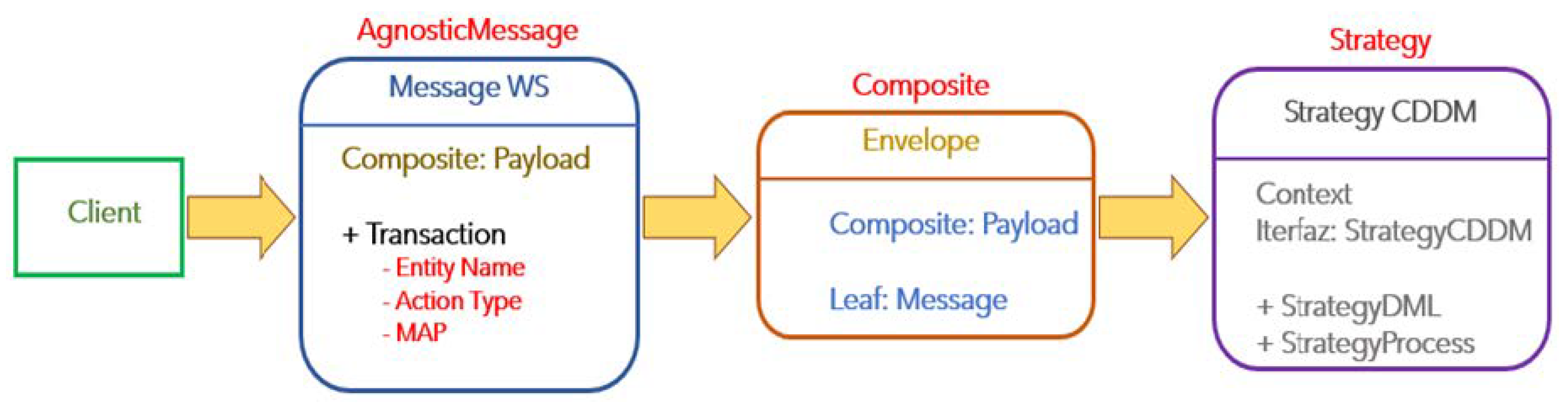
Figure 2.
The Agnostic Message component.
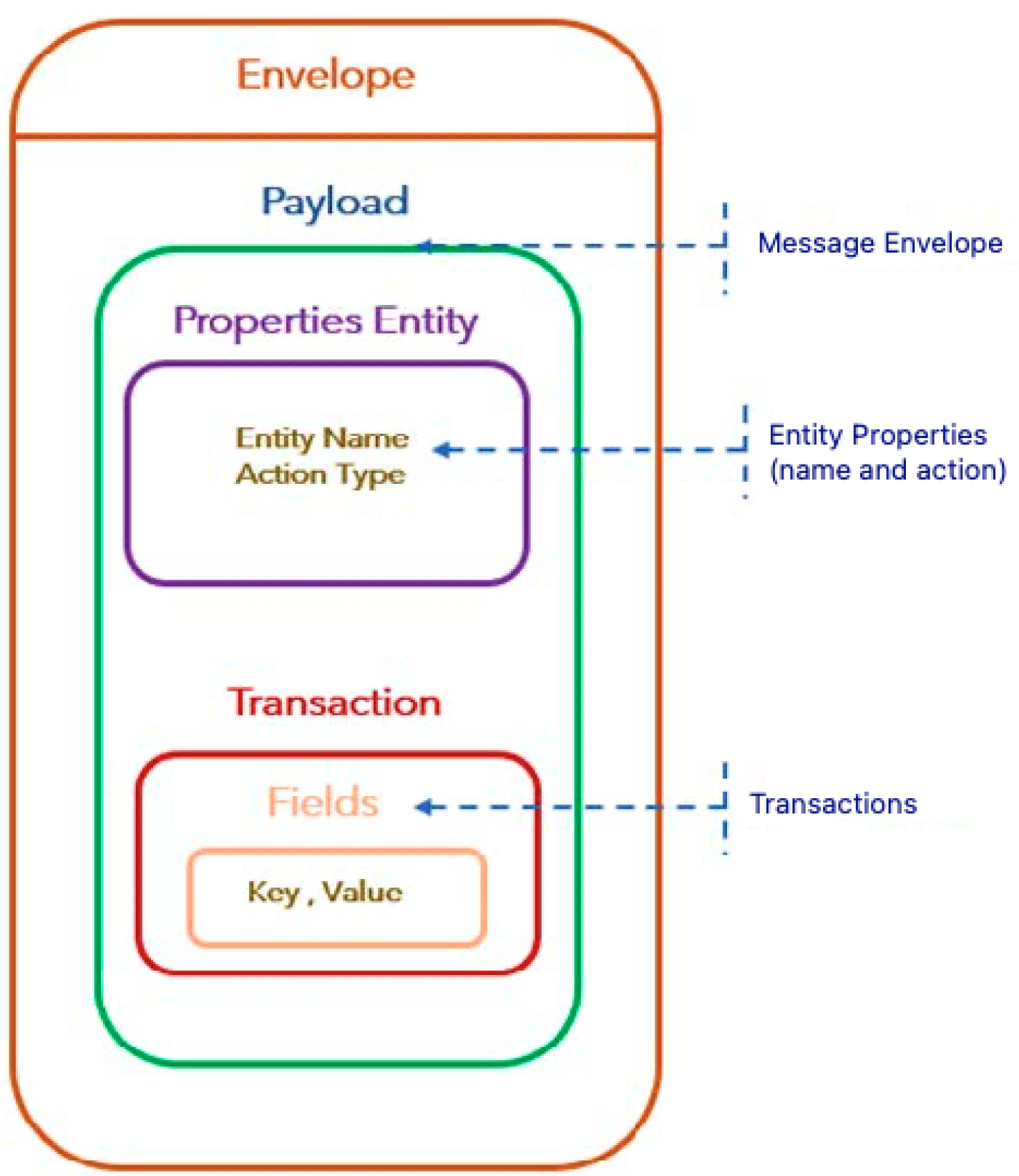
Figure 3.
The Agnostic Message XSD structure.
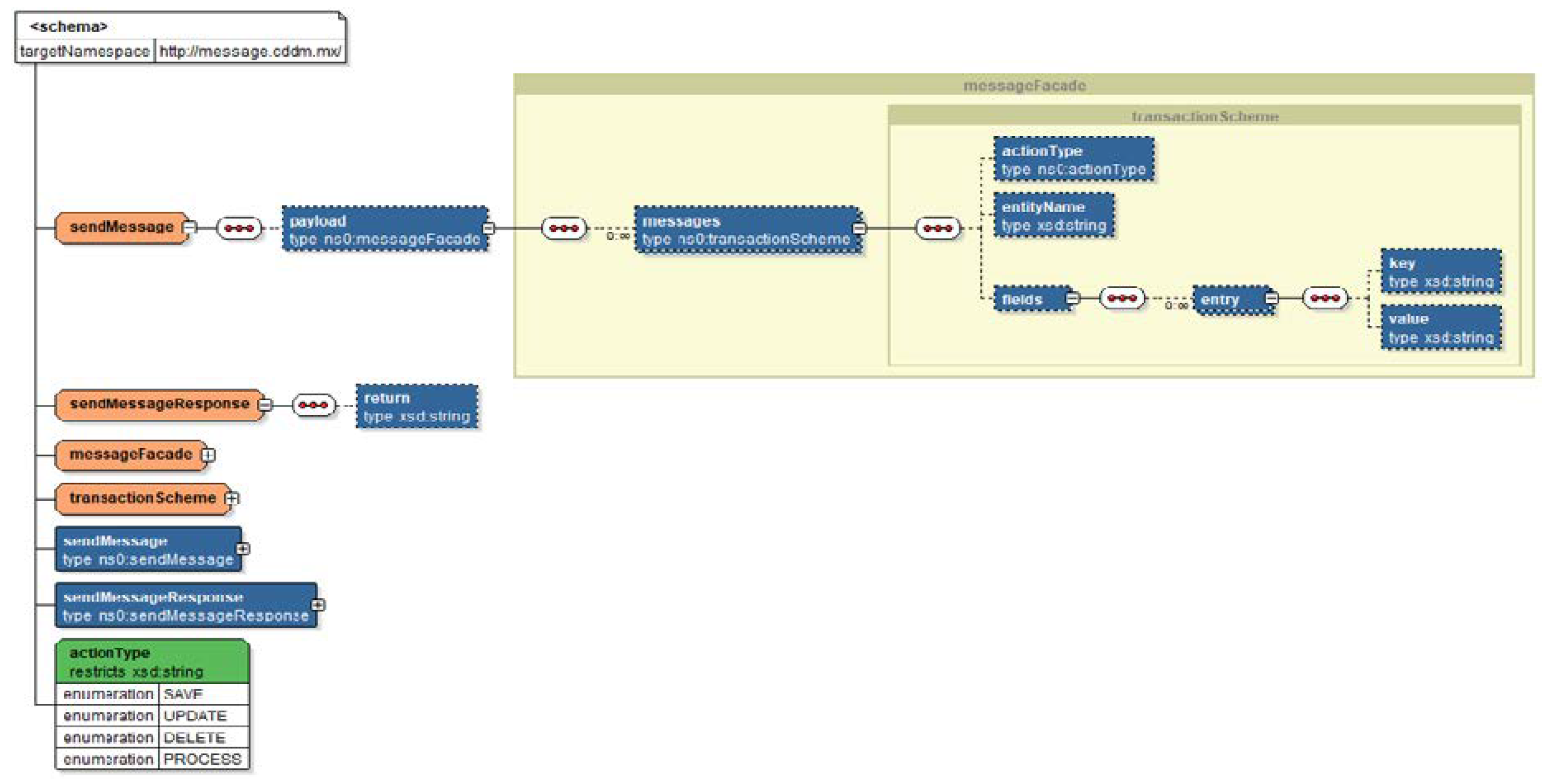
Figure 4.
The WSDL Agnostic Message consumption example by SoapUI tool.
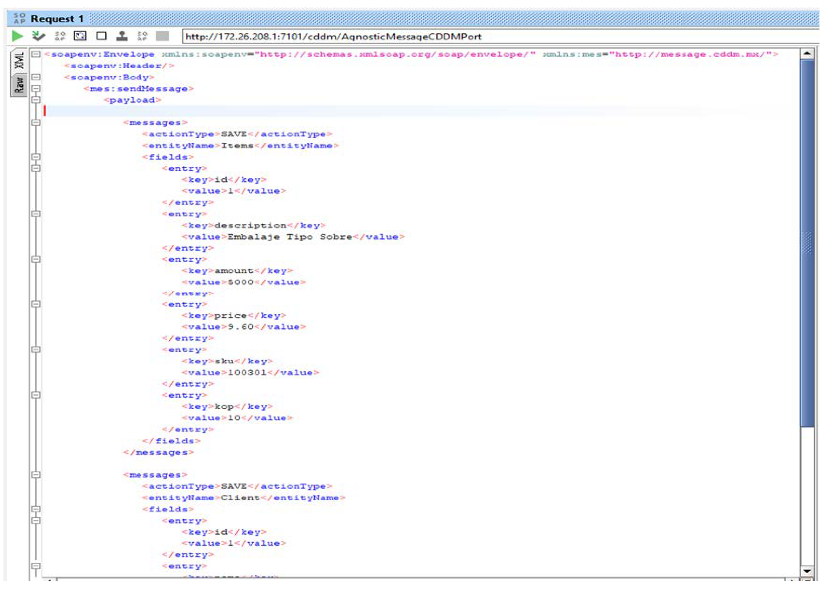
Figure 5.
The representation of the implementation of the Agnostic Message compound.
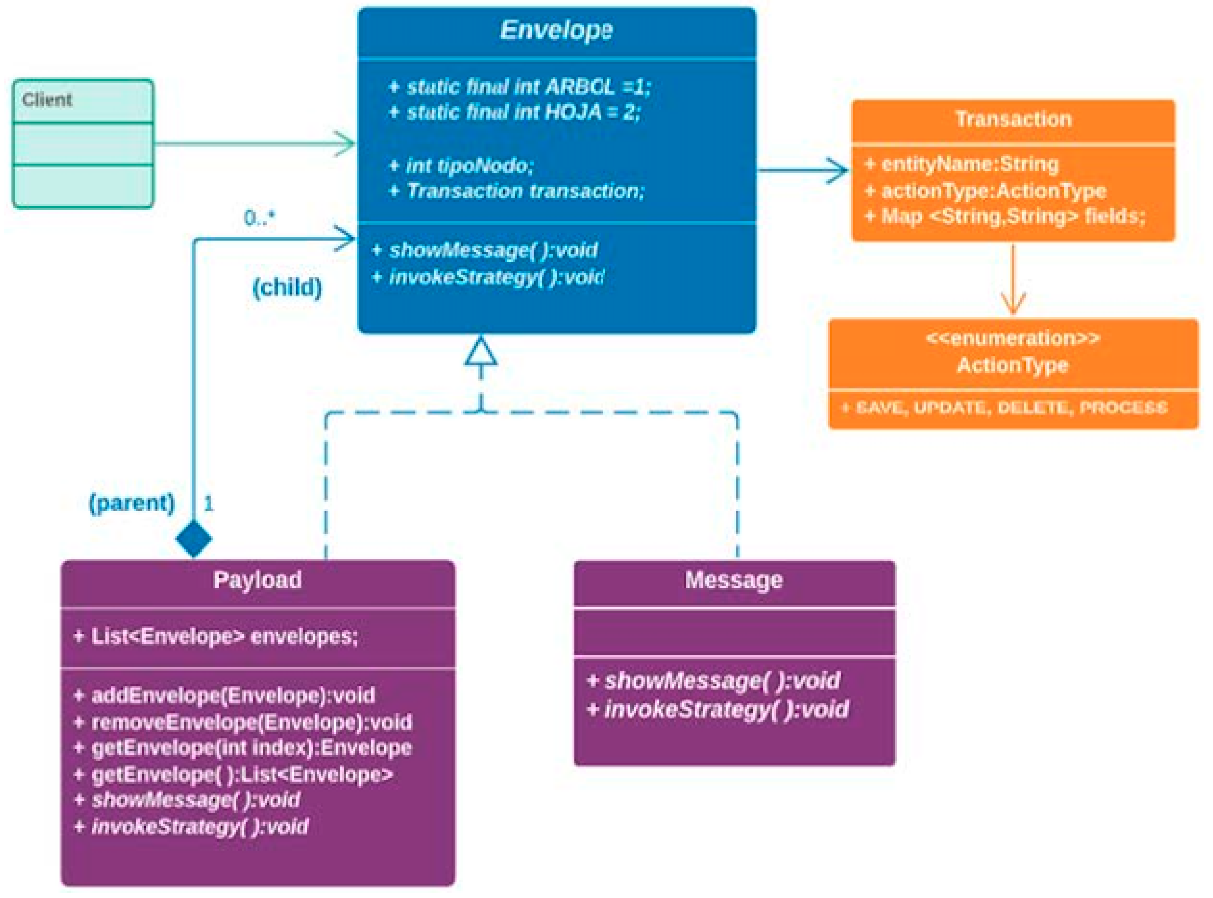
Figure 6.
Representation of StrategyCDDM strategy implementation.

Figure 7.
The DCDM architecture functionality in a sequence diagram.
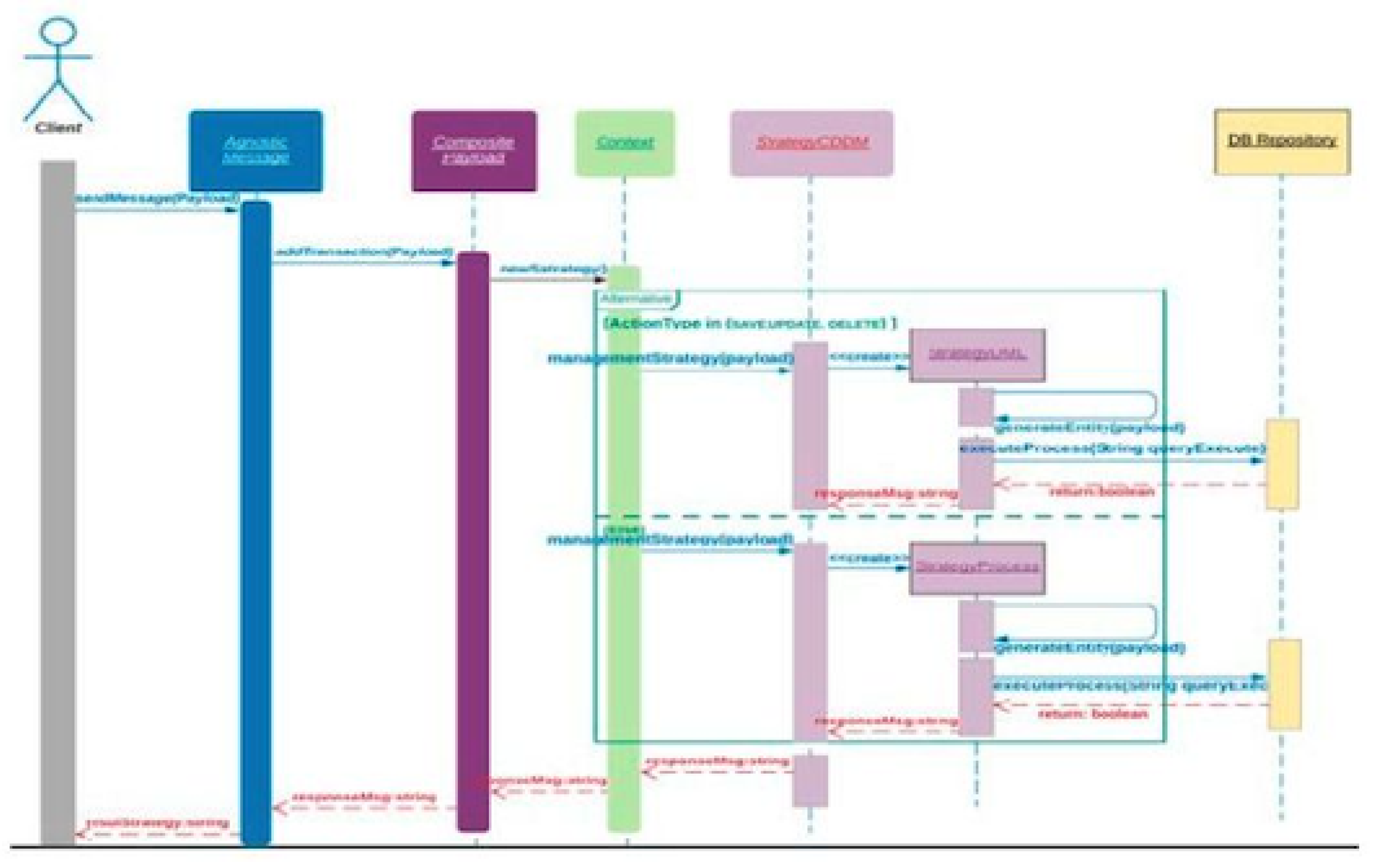
Figure 8.
SOAP Web Service for the AgnosticMessageCDDM.
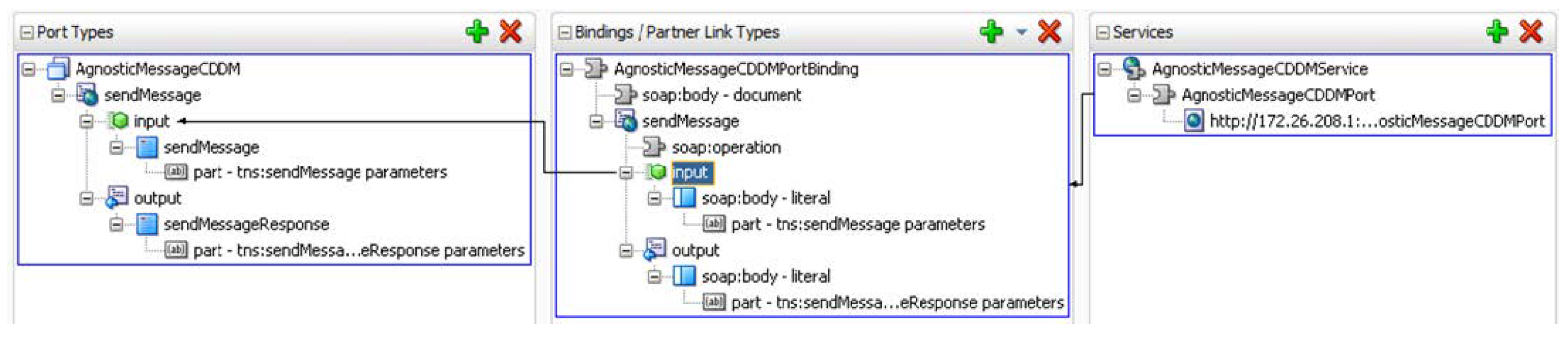
Figure 9.
Final DCDM architecture Project Structure implemented for this application example.
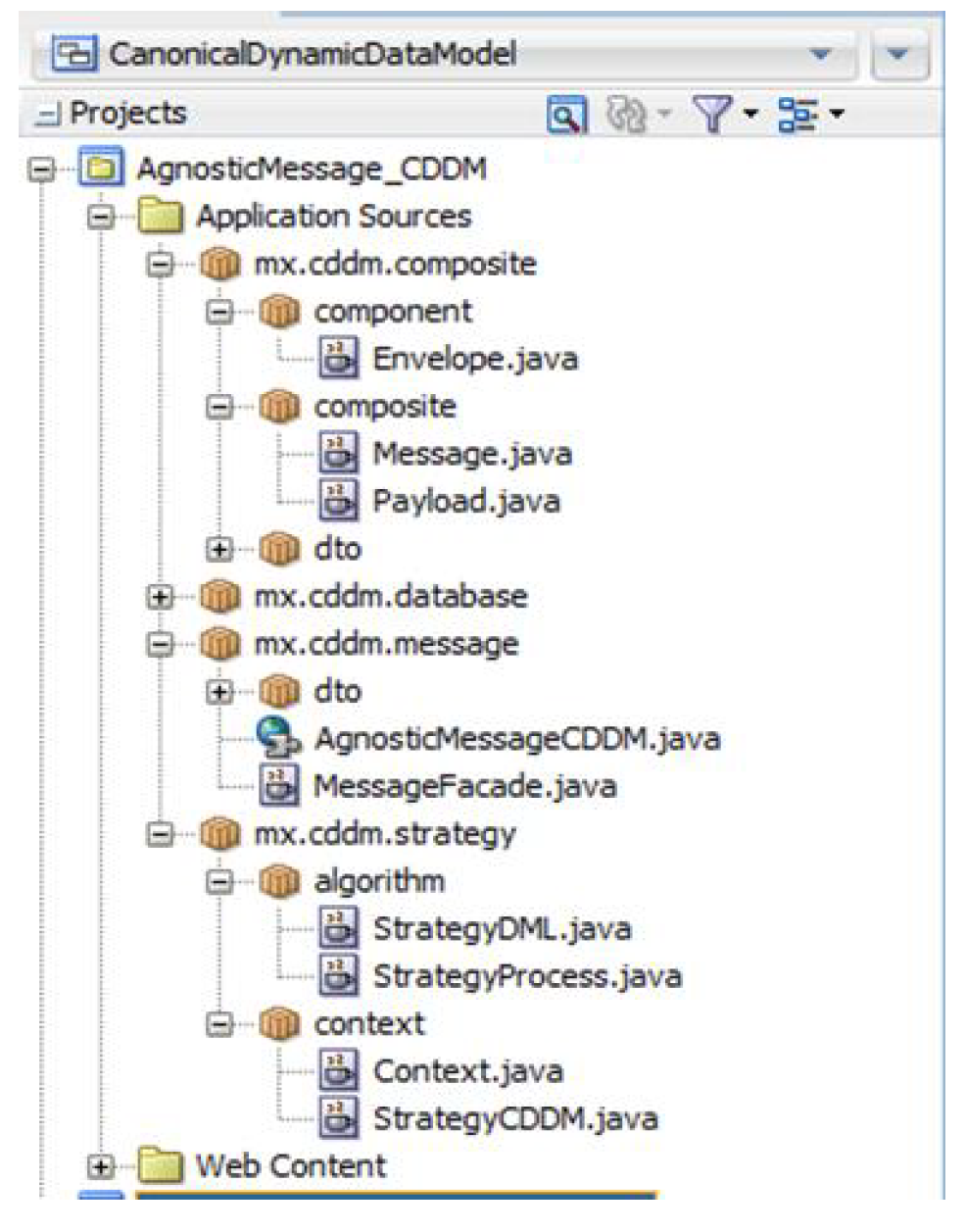
Figure 10.
Entity Items structure in PostgreSQL.

Figure 11.
AgnosticMessageCDDM deployment in WebLogic Server 12c.
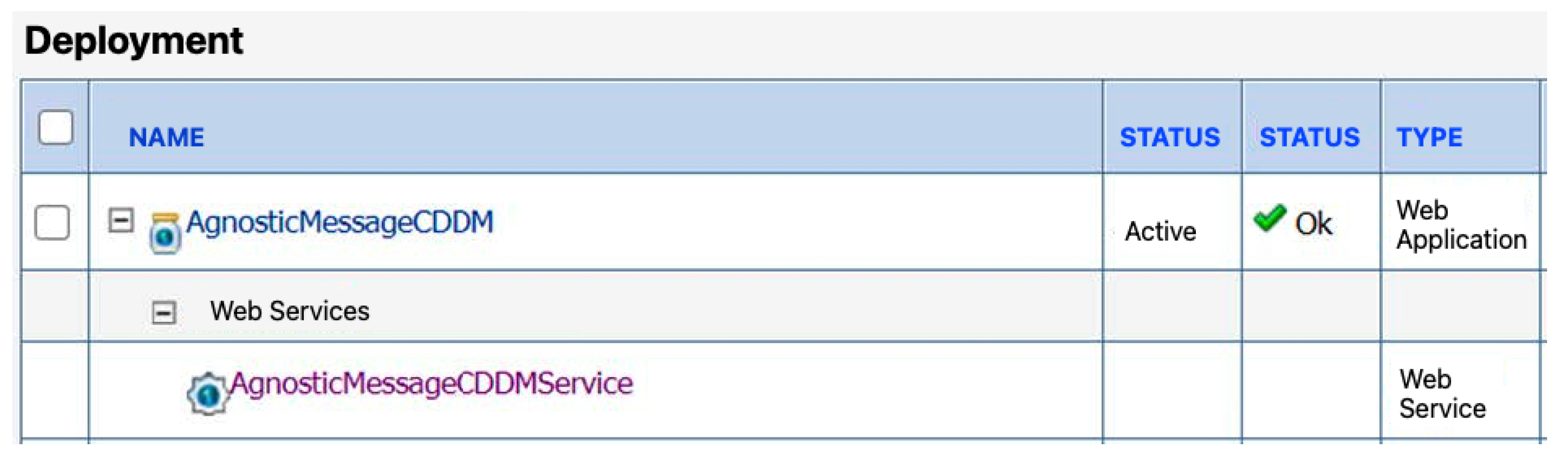
Figure 12.
Data from he clients integrated in the entity.
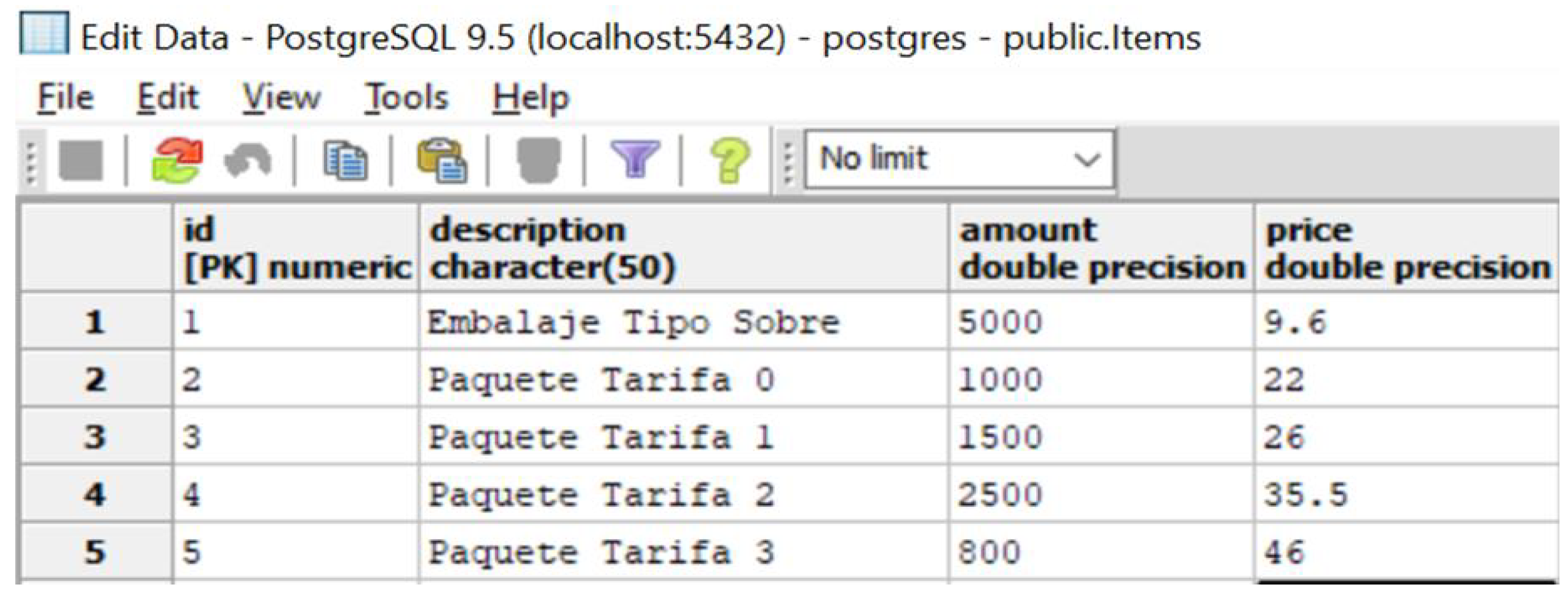
Figure 13.
Columns and data integrated in the entity after the execution of the test case appliying the CDDM architecture.
Figure 13.
Columns and data integrated in the entity after the execution of the test case appliying the CDDM architecture.
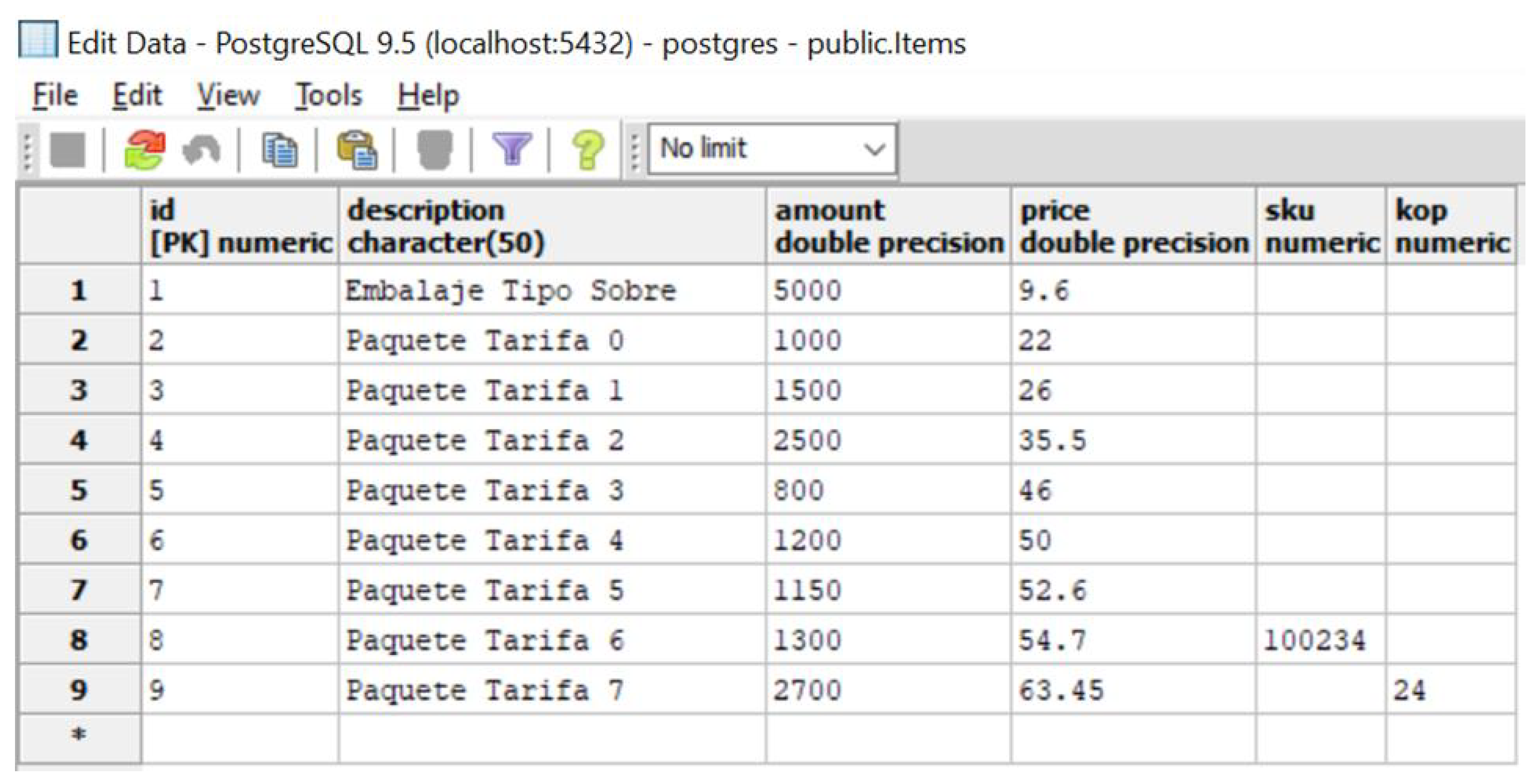

Table 1.
Test Case description.
| Software | Operating System: Windows 10. |
| Web Server: WebLogic 12c. | |
| Data Base Management System: PostgresSQL 9.5. | |
| WSDL Client: SoapUI 5.4.0. | |
| Platform: Java 8. | |
| Hardware | HP EliteBook, RAM 8GB, Core i5 1.80 GHz. |
| Goal | Validate the decoupling at data and external level in the platform integration, using four clients connected to the integration service, two of them will have to send two more data that were added to the Items entity of the PostgresSQL database. |
| Identifier | TC_Desacople_Item. |
| Name | Decoupling Entity Items. |
| Preconditions | The four clients must be connected to the service using the proposed architecture. |
| Phases | 1.- Connect each client to the service: create a connection to the service using the WSDL contract from the proposed architecture. |
| 2.- Send each client integration data: validate the integration of the four clients to the entity Items. | |
| 3.- Add two more fields to entity Items: add two fields in the database, to the entity Items: sku and kop. | |
| 4.- Use one client (from the four clients) to send the new field key and value: add in one client the value: 100234 to the field sku | |
| 5.- In another client send the second field added and its value: in the second client send the value: 24 for the field kop. | |
| 6.- Send same data for the two fields (no changes): validate the integration of the new data sku 100234 to the entity Items. | |
| 7.- Send data from the third client to the service: validate the integration of the new data kop 24 to the entity Items. | |
| 8.- Send data from the fourth client to the service: in the two previous customers send back information that has always been sent, these customers will not have to present any errors. |
Disclaimer/Publisher’s Note: The statements, opinions and data contained in all publications are solely those of the individual author(s) and contributor(s) and not of MDPI and/or the editor(s). MDPI and/or the editor(s) disclaim responsibility for any injury to people or property resulting from any ideas, methods, instructions or products referred to in the content. |
© 2023 by the authors. Licensee MDPI, Basel, Switzerland. This article is an open access article distributed under the terms and conditions of the Creative Commons Attribution (CC BY) license (http://creativecommons.org/licenses/by/4.0/).
Copyright: This open access article is published under a Creative Commons CC BY 4.0 license, which permit the free download, distribution, and reuse, provided that the author and preprint are cited in any reuse.


