1. Introduction
Selective laser sintering (SLS), one of the most popular 3D printing techniques, is a layer-by-layer manufacturing process at which the laser energy is used to fuse the particles of a thermoplastic powder in selected areas that matches the layer cross-section of object 3D model. The unfused powder provides support for the object being printed thus eliminating the need for additional supporting structure, which makes SLS a favorable technique for additive manufacturing of objects with complex geometries [
1]. Besides being used for a long time as a rapid prototyping technique, SLS is currently being used to produce small-to-medium size patches of polymeric objects.
Among the few pure materials suitable for SLS process, polyamide 12 (PA12) is considered as the most popular thermoplastic powder because of its favorable sintering properties which include good powder flowability, low melt viscosity, and a wide range between melting and crystallization temperatures [
2]. Even though PA12 parts prepared by SLS process have high chemical/environmental stability, reasonable mechanical properties, high impact resistance, and acceptable wear resistance, application of SLS to modern industries called for composite materials based on PA12 with tailored mechanical and tribological properties [
3,
4,
5]. Therefore, fillers in the form of either particulates, fibers, or combination of both have been introduced to enhance the mechanical and/or tribological properties of laser-sintered functional parts. The most common particulate fillers include graphite, molybdenum disulfide (MoS
2), polytetrafluoroethylene (PTFE), boron nitride (BN), and glass beads [
6,
7], while carbon fibers, glass fibers, and aramid fibers are the widely used synthetic fibers for reinforcement of polymer matrix [
8].
Recently, polymeric composites have proven to be good replacements for traditional materials in modern applications that require high strength-to-weight ratio such as aerospace, automotive, motorsport, and sports equipment. Hence, due care must be paid when designing the polymer composite for a specific application. proper selection of particulate/fiber material, shape and size, weight ratio, and surface treatment is extremely important. The properties of fiber-reinforced polymer composites are extremely sensitive to fiber weight fraction, fiber length, fiber orientation, fibers preprocessing, and fiber/matrix adhesion [
9]. As the properties of SLS fabricated parts are orientation dependent [
10,
11,
12], it was found that reinforcement with either particles or short fiber enhances the homogeneity of polymer composites prepared by SLS process [
13,
14], while introducing long or continuous fibers as a reinforcement result in directional properties of the fibrous composite [
9]. Further, the ease by which short fibers are processed saves manufacturing costs considerably rendering them most suitable for reinforcement of polymer matrices in additive manufacturing processes [
15]. Among the short fibers used for reinforcement purposes, carbon fibers (CF) are the most widely used fibers to improve the mechanical properties of polymer composites used in automotive and motorsport industries. Furthermore, as neat polymers are thermal insulators, reinforcement with carbon fibers enhances the thermal conductivity of polymeric composites significantly. Nevertheless, although reinforcement of thermoplastic matrix with short carbon fibers improves the tensile strength and wear resistance, decreases the coefficient of friction and frictional heating, and enhances the thermal conductivity of thermoplastic composites, it was found that the elongation at break has decreased significantly [
16,
17,
18]. Accordingly, abrasive wear resistance of carbon fiber-reinforced polymers (CFRPs) is unsatisfactory. Moreover, in dry sliding conditions, it was reported that fiber crushing results in fiber thinning followed by fibers pull-out of the matrix which in turn result in unstable frictional properties [
19,
20]. Therefore, reinforcement with short carbon fibers can efficiently promote the mechanical rather than the tribological properties of thermoplastic polymers. As the short carbon fiber-reinforced polymers are being used in applications where it is prone to direct contact with metallic/polymeric counterparts, it becomes inevitable to improve the friction and wear characteristics of such composites. For this purpose, solid lubricants in the form of particulate fillers have been employed to boost the lubricity of carbon fiber-reinforced polymers.
Graphite is a popular solid lubricant which has been used extensively to improve lubricity of tribo-surfaces. The lubricating effect of graphite stems from its distinctive layered crystal structure in which carbon atoms are bonded covalently in a hexagonal pattern within each layer, and layers are bonded to each other by means of weak Van der Waals forces. As a result, the bulk shear strength of graphite is always lower than the interfacial shear resistance allowing graphene layers to be easily removed and transferred to the counter-surface in sliding contact thereby reducing the coefficient of friction and improving the wear resistance of matrix [
21,
22]. In addition, graphite as a filler enhances the mechanical properties and thermal conductivity of polymer matrix [
21]. Hence, to improve the tribological properties of thermoplastic matrix and maintain prominent mechanical properties, graphite powder can be introduced as a filler of carbon fiber- reinforced polymer. By combining the effects of graphite as a solid lubricant and short carbon fibers as a reinforcement of thermoplastic matrix, the resulting composite can have enhanced tribological as well as mechanical properties.
With PA12 as a thermoplastic matrix, graphite-filled carbon fibers-reinforced PA12 composite can meet the increasing demand of a stiff, lightweight, thermally conductive, low friction, wear resistant, and chemically stable material for aircraft, automotive, and Motorsport industries. The composite can be ideal for applications with fixed and movable joints operating at low temperatures (less than the glass transition temperature of PA12) and under a wide range of bearing pressures in harsh environments. Moreover, with graphite powder, short carbon fibers, and PA12 as the constituents, the composite is most suitable for SLS processing which facilitates the fabrication of complex functional geometries based on this composite. However, so far, very little has been reported regarding the tribological characteristics of a reinforced thermoplastic filled with a solid lubricant, and very few articles among them are concerned with composites prepared by SLS technique [
14,
23,
24,
25]. The few reported results showed that inclusion of either PTFE or MoS
2 could effectively reduce the coefficient of friction of laser-sintered PA12 by forming a homogenous transfer film on the counter-surface [
14], and that 5 - 10% weight fraction of graphite was sufficient to significantly improve the tribological characteristics of PA6 [
23].
Hence, this experimental study is dedicated to exploring the tribological features of graphite-filled carbon fiber-reinforced PA12 (CFR-PA12) composite prepared by SLS process. Given that the properties of SLS parts are orientation-dependent, the test specimens are aligned along four orientations in the build chamber of the SLS machine. The tribological characteristics of graphite-filled CFR-PA12 composite are examined using pin-on-disc tribometer in dry sliding conditions. Frictional heating as well as the friction-induced noise are measured, and wear resistance of the composite is evaluated. Finally, scanning electron microscopy (SEM) is used to investigate the wear patterns that dominated the worn tribo-surface of test specimens. The results from this study, when compiled with relevant findings in open literature, can contribute to a better understanding of the tribological characteristics of graphite-filled CFR-PA12 composite prepared by SLS under dry sliding conditions; this can facilitate widening the applicability of this composite in demanding industries.
2. Materials and methods
2.1. Selective Laser Sintering of test specimens
The test specimens were prepared by selective laser sintering (SLS) technique using powder mixture composed of polyamide 12 (PA12) powder as a matrix, 5% weight ratio of graphite powder, and 2.0 % weight ratio of short carbon fibers. The powder mixture was developed in-house by Graphite Additive Manufacturing Ltd (UK) and supplied by EOS GmbH. Specimens in the form of pins with 4 mm diameter and 25 mm length were fabricated in SLS build chamber along 4 different orientations. Fabrication parameters are given in
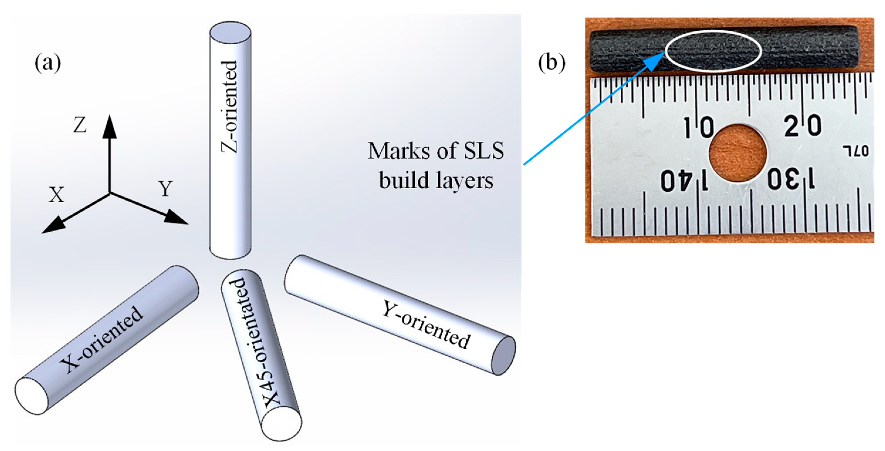
Table 1. The specimens were oriented along the X-axis, Y-axis, Z-axis, and at 45° to the X-axis (X45) in the build chamber, as shown in
Figure 1(a), and were built along the positive Z-axis. The tribo-surfaces of test specimens are perpendicular to each orientation. It is worth noting that the SLS fabrication parameters outlined in
Table 1 were selected by the manufacturer for optimum part density, physical properties, and mechanical properties. Cosmetic finishing (light media blasting) was applied to remove the unsintered powder particles from specimen surface after drawing out from the build chamber.
Figure 1(b) shows clear marks of SLS build layers in X-oriented specimen; however, this was not visible on the surface of other specimens.
2.2. Pin-on-disc tribometer
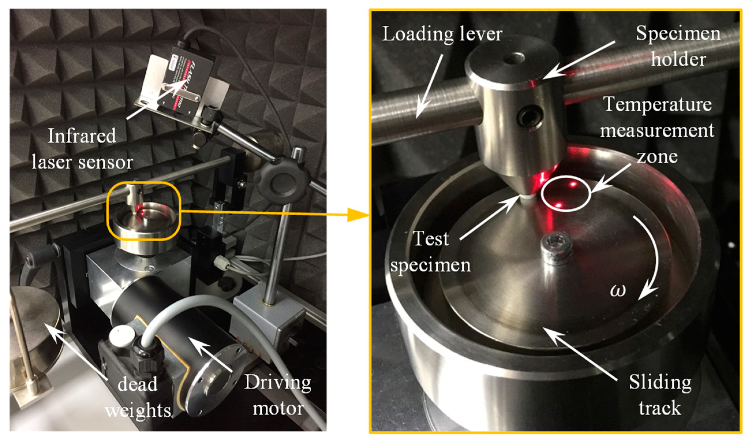
Dry sliding characteristics of graphite-filled CFR-PA12 composite were investigated using pin-on-disc tribometer at which the pin-shape test specimen is inserted into a pin holder located at the middle of a loading lever. Then, the pin is loaded against the steel disc by means of a hung deadweight at the end of the loading lever, see
Figure 2. The stainless steel disc is rotated by means of a drive unit while the specimen is fixed. To maintain dry sliding conditions at the interface, 99.9% ethanol was used to clean the disc surface to remove any dirt, oily substance, or adsorbed matter, and the experiments were conducted in dry environment (air humidity was less than 10%). Several stainless steel discs were manufactured with close surface roughness so that every test specimen is examined against fresh disc tribo-surface; this was adopted to rule out the effect of formed transfer film on friction and wear behavior at the interface. Surface roughness of steel discs was measured using SURFTEST SJ-210, and the average surface roughness (Ra) value in radial direction (i.e., perpendicular to sliding direction) of all disc surfaces was 0.34 ± 0.03 microns.
2.3. Experimental measurements
The measurements were conducted to evaluate the coefficient of friction (COF), approximate contact temperature, friction-induced noise, specific wear rate, and to investigate the dominant wear pattern along each build orientation. To evaluate the COF at composite/disc interface, the friction force was measured by means of a double-bending beam force sensor along with NI-9237 module and NI-compactDAQ controller [
7,
19]. A Labview code was developed to manage the sensor signal in which a moving average function was used to return the average value of the COF every 0.5 s.
Since measurement of the actual contact temperature is not straightforward, a close approximation of contact temperature was obtained by measuring the disc temperature very close to the trailing edge of the pin, see
Figure 2 For this purpose, an infrared laser temperature sensor (KEYENCE-FT-H30), along with a digital amplifier unit (FT-50AW) were used to detect the frictional heat emitted from a circular area of 6 mm diameter in the vicinity of contact zone. To measure the friction-induced noise, the pin-on-disc tribometer was arranged inside a semi-anechoic chamber lined with a high-density polyurethane acoustic foam. The noise level was measured using a digital sound level meter (GM 1357). Arduino Uno microcontroller board (SMD R3) was used to manage the output signals of the infrared laser temperature sensor and the digital sound level meter, and a moving average function was applied to calculate the average values of contact temperature and frictional noise level every 0.5 s.
Finally, a thin film of gold (less than100 Å) was deposited on the worn tribo-surfaces of graphite-filled CFR-PA12 specimens in a plasma sputtering device (sec-MCM-100P ion sputtering coater) to render them electrically conductive, and then scanned with scanning electron microscope (SNE-4500M Plus) to determine the wear patterns that predominated the tribo-surface.
3. Results and discussions
The results presented in this section outline the tribological characteristics of graphite-filled CFR-PA12 composite prepared using SLS under dry sliding conditions against steel counter surface. Tribological characterization was conducted using pin-on-disc tribometer where the pin is a rod of 4 mm diameter, 25 mm length, and made of laser-sintered graphite-filled CFR-PA12 composite while the disc is made of stainless steel. The applied load on the pin was 50 N, thus the apparent contact pressure at pin/disc interface was about 4 MPa, however the actual contact pressure is much higher than the apparent value as the real contact area is much smaller than the apparent one [
26]. The sliding track radius was 20 mm, and the disc rotation velocity was 120 rpm, thus the pin sliding speed was about 250 mm/s. Dry sliding experiment was conducted for a duration of 45 minutes to explore the steady state performance of graphite-filled CFR-PA12 composite. The current experimental conditions are given in
Table 2.
The results presented in the following sections address the potential effects of part orientation on the coefficient of friction, friction-induced noise, contact temperature, and specific wear rate of laser-sintered graphite-filled CFR-PA12 composite under dry sliding conditions against steel countersurface.
3.1. Coefficient of friction (COF)
There are two components of friction: mechanical component representing the material resistance to ploughing/Microcutting by the asperities of the counter surface, and adhesion component representing the resistance to shearing of adhesive junctions at spots of real contact. Indeed, the adhesion component contributes most to the frictional resistance of polymers and polymer composites [
27,
28].
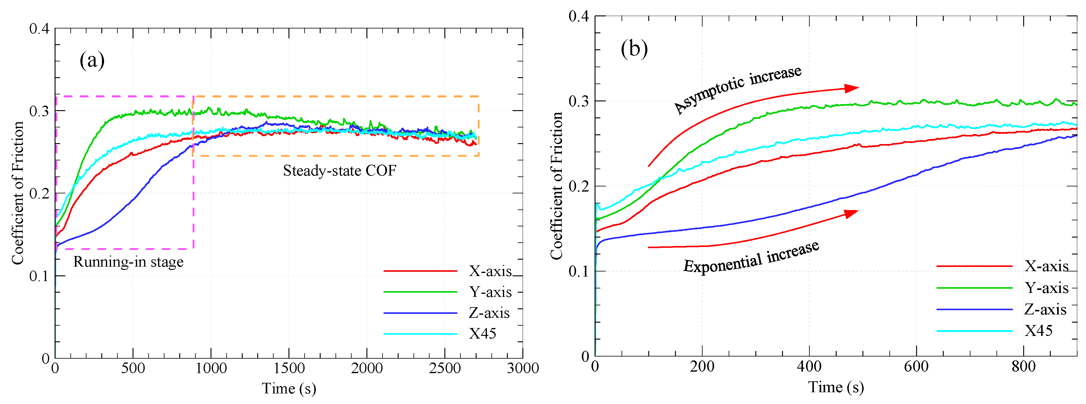
Figure 3 shows the variations of the COF over sliding time for graphite-filled CFR-PA12 specimens with different orientations. The results from
Figure 3(a) reveal that there has been a sharp increase in the COF of X-oriented, Y-oriented, and X45-oriented specimens during the running-in stage, while the Z-oriented specimen shows a gradual increase of COF during the same process. The running-in process lasts for few minutes (less than 10 minutes) then a steady state is attained at which the COF of all specimens is remarkably close. Interestingly, the steady state COF of all specimens is about 0.26 and is likely to fall behind this value as sliding continues. Such low COF indicates that abrasive wear dominates the tribo-surface of graphite-filled CFR-PA12 specimens regardless of part build orientation. Indeed, reinforcing PA12 with short carbon fibers decreases the elongation at break considerably and, consequently, reduces abrasive wear resistance of CFR-PA12. Additionally, introducing graphite powder as a filler further decreases the elongation at beak and hence the abrasive wear resistance of the specimens according to Ratner-Lancaster correlation [
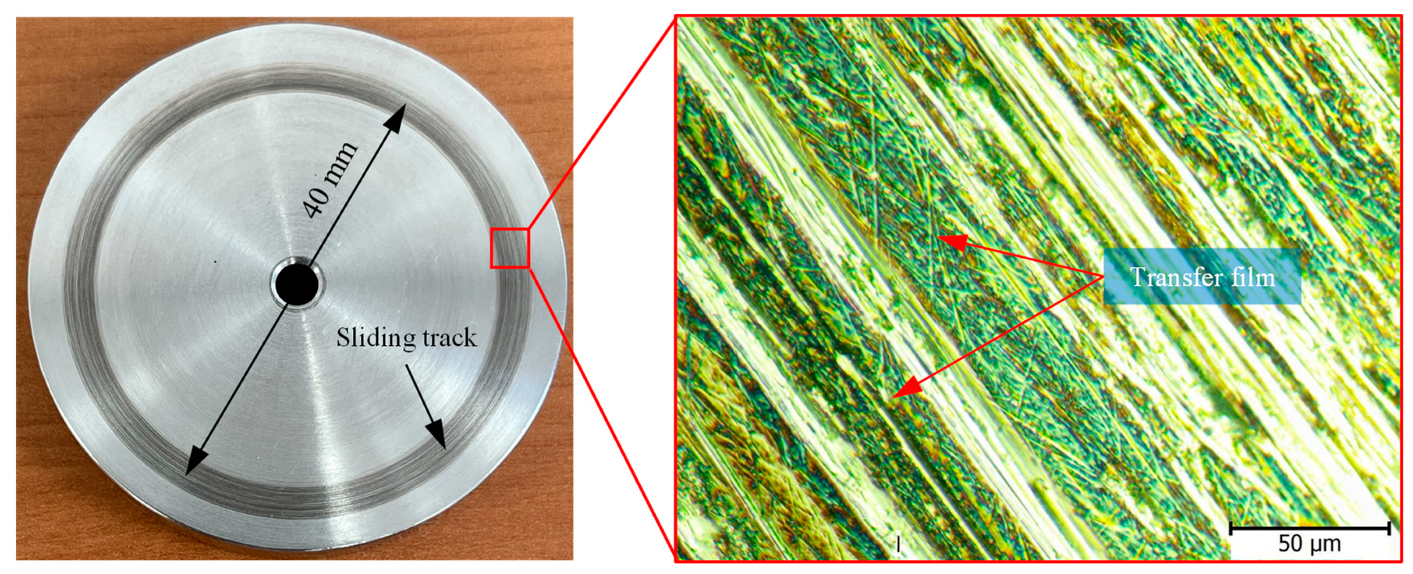
28]. Because of the lamellar structure of graphite, upon sliding against steel surface, the weak Van der Waals forces of attraction between layers allows graphite layers to be easily sheared away and be transferred into the disc surface thus increasing the interface lubricity and decreasing the steady state COF;
Figure 4 shows evidence of a transfer film attached to the sliding track on disc surface after testing graphite-filled CFR-PA12 samples. Consequently, transferred graphite layers on disc surface decreases the interfacial shear strength of adhesive junctions rendering all junctions to be sheared away at the interface rather than at polymer subsurface, and hence the frictional heating, friction-induced noise, and wear volume are decreased significantly.
The gradual increase of the COF for Z-oriented specimen at running-in stage, shown in
Figure 3(b), is attributed to the corresponding gradual increase in real contact area. At initial stages of running-in process, carbon fibers contribute to support the normal load; however, as rubbing continues, the PA12 layer that encapsulate the fibers and graphite particles is continuously removed away rendering the fibers and graphite particles prone to direct contact with disc surface. Consequently, thinning of carbon fibers occurs and more PA12 spots get into contact with disc surface that result in a corresponding increase in adhesive resistance [
19], hence the COF of Z-oriented specimen increases accordingly.
Contrarily, the steep increase in COF of specimens built along X, Y, and X45 directions during the running-in process is attributed to the frequent formation and shearing out of adhesive junctions at sliding interface since it was reported that most frictional resistance is associated with adhesion at the interface until a stable transfer film of graphite layers are formed on the disc surface, then a steady state COF is reached and manifested by a uniform wear rate. Indeed, the highest wear volume of polymer composites is associated with the running-in process [
29].
3.2. Friction-induced noise
In polymer tribology, friction-induced noise is attributed to the adhesive component of friction at sliding interface. Adhesion bonds are formed either at surface or subsurface zones of real contact. Surface adhesive bonds are formed as the gap size between polymer and countersurface is less than 100 Å by means of weak Van der Waals molecular forces. Meanwhile, subsurface adhesive bonds are formed at both sides of ploughing/cutting asperities of the harder surface. In both cases, breaking of adhesive bonds results in what is termed friction-induced noise which is a ruling parameter in polymer tribology. Therefore, by reducing the COF, the friction-induced noise is reduced significantly. The effective way to reduce the adhesive component of friction is to lubricate the interface either using liquid or solid lubricant.
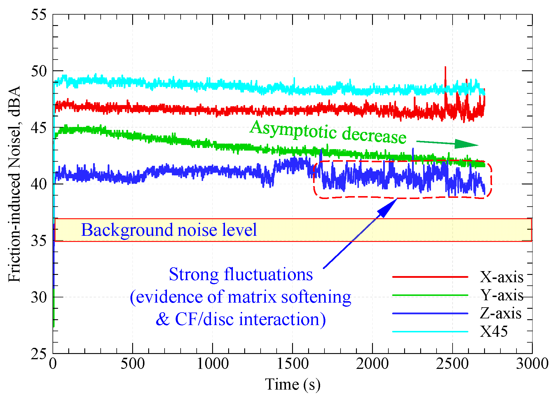
Figure 5 shows frictional noise variations with sliding time for graphite-filled CFR-PA12 specimens of various orientations. It is worth noting that the background noise in the experimentation site was 35–37 dBA.
Although the steady state COF of all specimens is remarkably close, the results from
Figure 5 depict that the test specimens have diverse levels of friction-induced noise throughout the test duration. A possible explanation for this inconsistency might be that the pattern of friction at running-in stage has a prolonged effect on the friction-induced noise. The repeated formation/breaking of adhesive junctions between X-, Y- and X45-oriented specimens and disc surface results in steep growth of both the COF and friction-induced noise at running-in stage. It is apparent from
Figure 3(b) and
Figure 5 that, during the running-in stage, the COF increases in an asymptotic manner and so does the friction-induced noise until steady state conditions are attained, and then the friction noise remains at the same level throughout the experiment duration. Another interesting finding from
Figure 4 and
Figure 5 is the remarkable synchronous pattern of evolution of friction-induced noise and COF for Y-oriented specimen at which the friction-induced noise asymptotically decreases as the steady state COF decreases. Another important remark from
Figure 5 is that the Z-oriented specimen has the lowest friction noise level, however with severe fluctuations. Since the COF of Z-oriented specimen still near the lowest value amongst all orientations throughout the test duration, this behavior may be attributed to the interaction between carbon fibers and disc surface [
19]; however, this explanation does not rule out the prominent effect of interfacial adhesion as the real area of contact increases with increasing sliding time. To emphasize the role of interfacial adhesion,
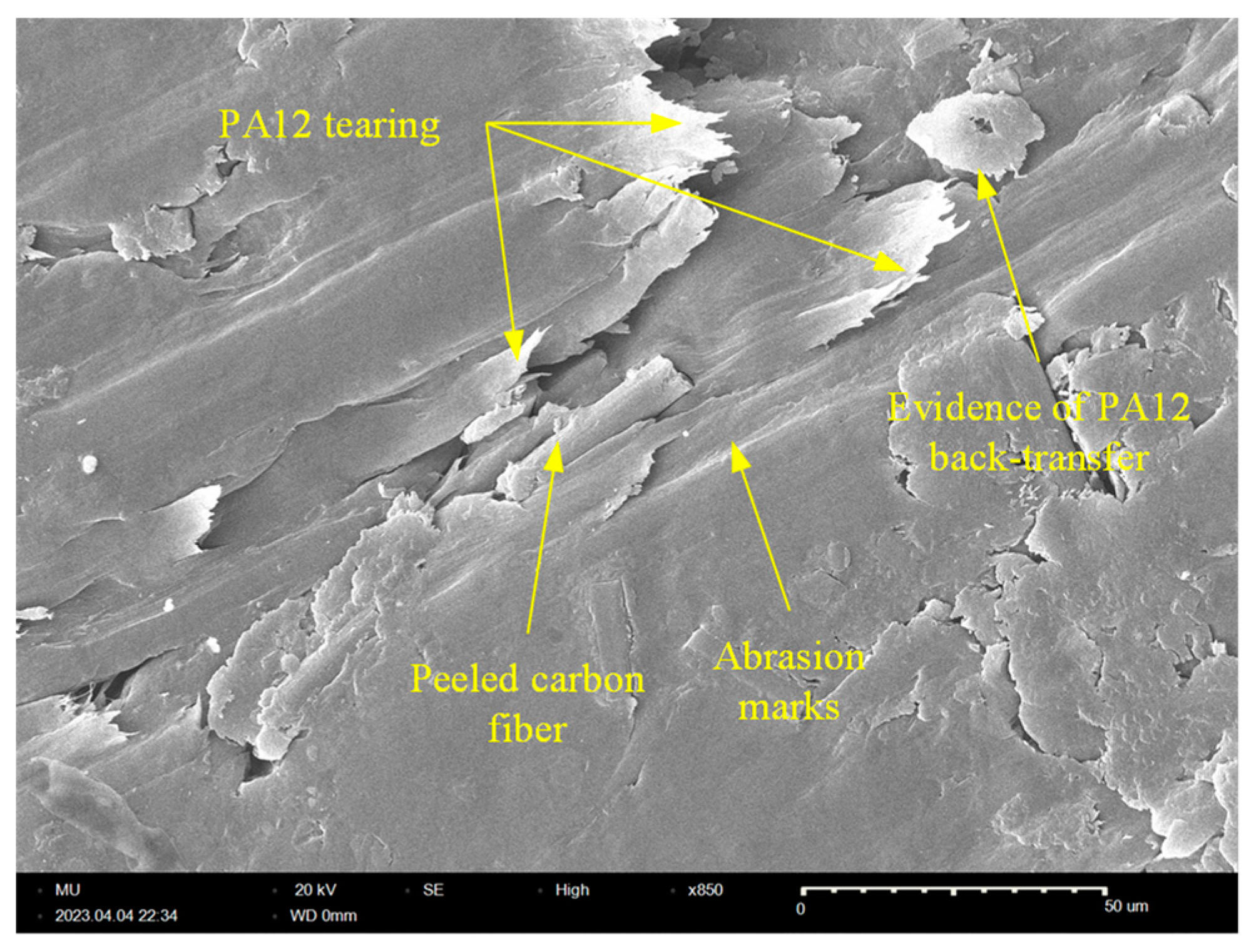
Figure 6 shows clear marks of strong tearing of PA12 matrix manifested by appearance of stringy tongues unfirmly attached to the surface. For tearing to occur, strong interfacial adhesion along with anisotropic cohesion properties must exist. Tearing results in the formation of PA12 wear flakes that may roll between surfaces or attached to a sliding surface [
30,
31,
32]. Similarly, the friction-induced noise of X-oriented specimen tends to exhibit strong fluctuations near the end of testing time. This may be influenced by the softening of PA12 matrix because of the cumulative frictional heating that fosters the formation of adhesive bonds which results in such an increase in frictional noise, see
Figure 6.
3.3. Contact temperature
When a thermoplastic slides against hard counter surface, the interfacial interaction results in frictional energy losses in one or more of the following forms: (1) losses due to subsurface plastic deformations by means of hard asperities (ploughing and/or Microcutting), (2) losses due to surface adhesion; (3) losses due to subsurface adhesion in ploughing and/or Microcutting, and (4) losses due to polymer hysteresis (difference between induced elastic deformation energy and the retained back-pushing elastic energy). Indeed, ploughing and Microcutting are principal sources of subsurface heating while adhesion can be a major source of surface as well as subsurface heating. Meanwhile, hysteresis losses contribute to subsurface heating. Moreover, repeated formation/rupture of adhesive bonds causes severe vibrations of subsurface polymer molecules that contributes to subsurface heating [
33].
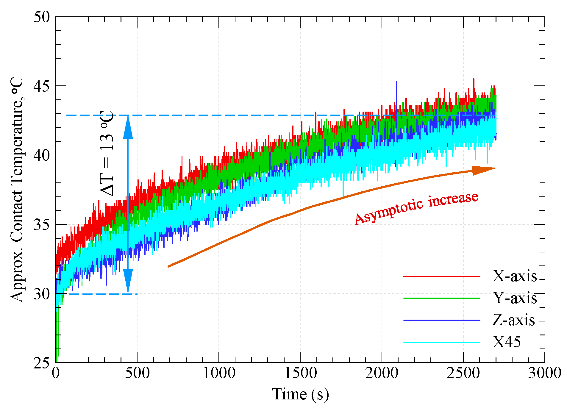
Figure 7 shows the variations of approximate contact temperature with sliding time for specimens built along the four different orientations. It is apparent from
Figure 7 that the approx. contact temperature increases in an asymptotic manner with increasing the sliding time, however there is no significant difference between the contact temperature of different specimens. Further, the cumulative increase of contact temperature is only 13
oC after 45 minutes of dry sliding. Indeed, the enhanced thermal conductivity of graphite and carbon fibers contribute to such thermal stability of graphite-filled CFR-PA12 composite regardless of build orientation. Additionally, the transfer film of graphite layers that formed on the disc surface acts to decrease surface and subsurface adhesion which is the major source of frictional heating in dry sliding conditions. The most interesting result from
Figure 7 is that increasing the sliding time is unlikely to cause a corresponding increase in contact temperature as the contact temperatures tend to reach an asymptote far below the glass transition temperature of amorphous regions of PA12 matrix. This result demonstrates the potential of this composite to replace conventional bearings operating in harsh environmental conditions.
3.4. Specific wear rate
Evaluation of material specific wear rate is an efficient method to visualize its wear resistance; wear resistance is proportional to the reciprocal of specific wear rate. The specific wear rate of polymer composite (Ks) depends on the wear volume (ΔV), normal load (F
N), and sliding distance (L) and is expressed as [
34]:
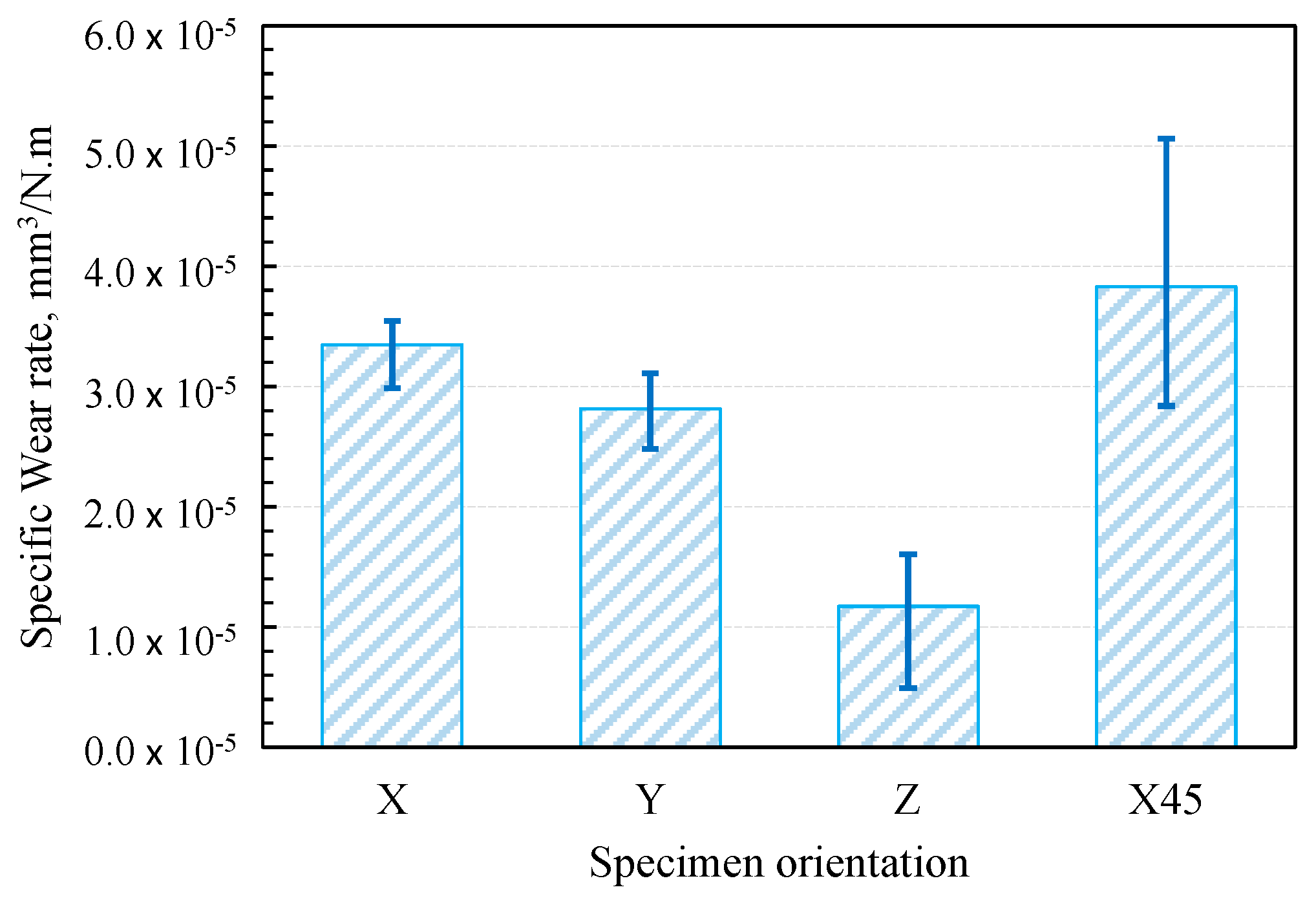
Figure 8 shows the specific wear rates of graphite-filled CFR-PA12 specimens built along the four different orientations. The results reveal that the Z-oriented specimen has the lowest specific wear rate and hence the highest wear resistance amongst all other orientations. Accordingly, the results from
Figure 8 are in good agreement with those obtained from
Figure 3,
Figure 4,
Figure 5,
Figure 6 and
Figure 7 as the Z-oriented specimen exhibited the lowest levels of COF and friction-induced noise. However, it is somewhat surprising that the X45-oriented specimen shows a comparatively high specific wear rate and hence a lower wear resistance although it has a comparable COF to other specimens. A possible explanation for this behavior might be the continuous removal of the transfer film from disc surface; it was found that the wear rate of polymers is dictated by the rate of removal of the transfer film from the countersurface, rather than by the rate of polymer transfer into the film [
28]. The transfer film can be removed from the disc surface by the peeling action of protuberant carbon fibers [
19]; this is manifested by the detected high-level of frictional noise of X45-oriented specimen, see Fig 5. Likewise, the high frictional noise can be evidence of strong surface and/or subsurface adhesion that leads to localized tearing of PA12 matrix and subsequent buildup of transferred layer on the disc surface. Eventually, the repeated rubbing causes such lumps of wear debris to be detached and replaced by a fresh migrating film. Such poorly attached transferred film is the main reason behind the increased wear rate of X45-oriented oriented specimen.
Nevertheless, it is important to bear in mind that the tribological characteristics of thermoplastic composites are susceptible to small variations in experimental conditions. Therefore, the abovementioned results cannot be extrapolated for conditions other than those mentioned in
Table 2. Hence, thorough investigations for wide range of experimental conditions combined with a proper machine learning (ML) model can help in fabricating components with customized tribological properties based on graphite-filled CFR-PA12 composite [
5]. Additionally, the results from
Figure 3,
Figure 4,
Figure 5,
Figure 6,
Figure 7 and
Figure 8 suggest that functional sliding bearing based on graphite-filled CFR-PA12 composite where the bearing surface is built normal to the Z-orientation can perform reliably under low sliding speeds and high contact pressure; such prominent features render the laser-sintered graphite-filled CFR-PA12 composite ideal for aerospace, motorsport, and electric vehicles applications.
3.5. Scanning Electron Microscopy (SEM)
The worn tribo-surfaces of the specimens were investigated using SEM to determine the prevailing wear patterns for the purpose of suggesting microstructural solutions to enhance the wear resistance of the composite.
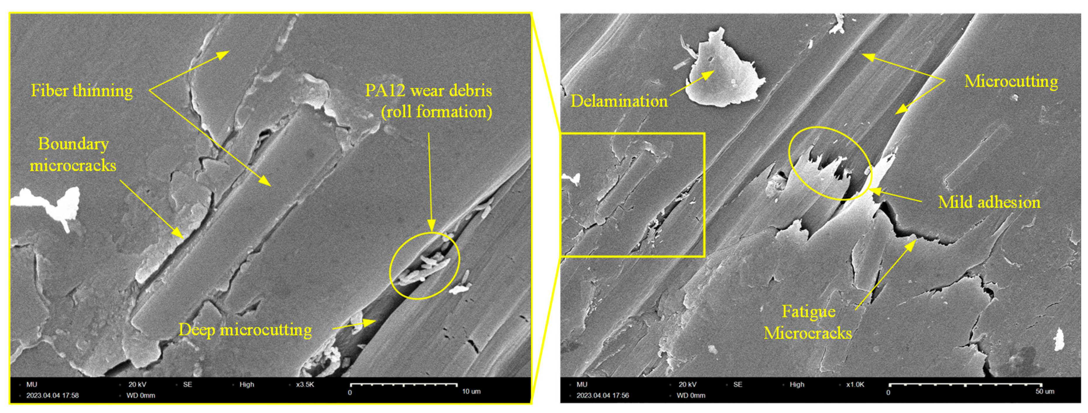
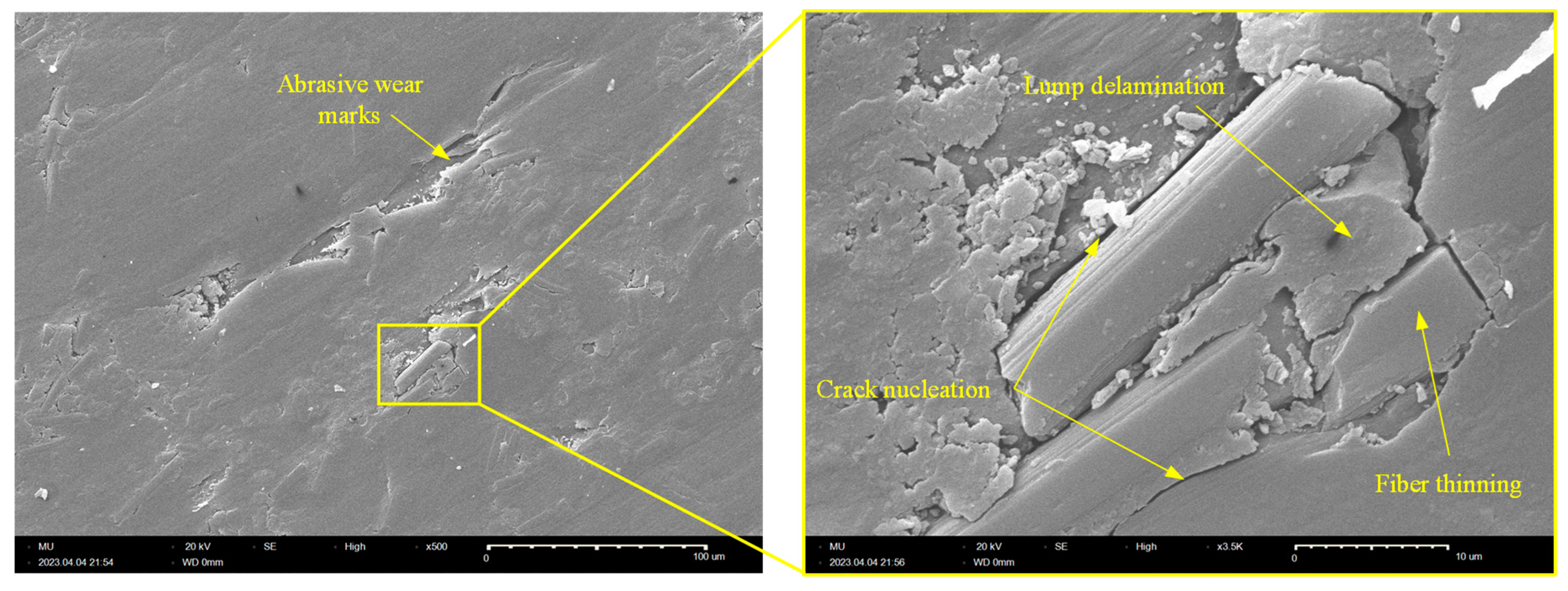
Figure 9 shows SEM picture of the worn surface of X-oriented specimen. The tribo-surface shows evidence of weak adhesion and is characterized by clear marks of abrasive wear in the form of deep Microcutting grooves. Further, the tribo-surface of X-oriented specimen features two types of microcracks: (1) boundary microcracks at CF/PA12 interface due to poor bonding that necessitate proper surface treatment of CF to enhance adhesion with PA12 matrix, (2) fatigue microcracks (aligned normal to sliding direction) due to repeated shearing of adhesive junctions at the interface. Additionally, fiber thinning was detected which supports the hypothesis that disc/fibers interaction contributes to the friction-induced noise of carbon fiber reinforced polymers (CFRPs). Moreover, the existence of tiny rolls of PA12 wear debris (i.e., roll formation) that are collected in deep micro cuts is evidence of weak interfacial adhesion. Furthermore, the tribo-surface of X-oriented specimen shows loosely attached PA12 lump as evidence of delamination. The delamination of PA12 matrix occurs as a result of the propagation and subsequent coalescence of surface microcracks (either fatigue microcracks or boundary cracks).
Similarly,
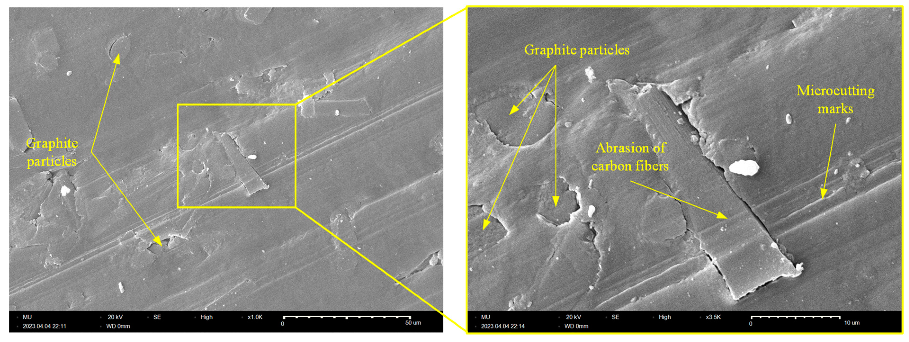
Figure 10 shows SEM picture of worn surface of Y-oriented specimen. The results from
Figure 10 indicates that abrasive wear is the dominant wear pattern of Y-oriented tribo-surface which is free from any signs of interfacial adhesion. Another interesting feature of the Y-oriented CF-PA12 tribo-surface is fibers thinning by pulverization action of steel countersurface that releases fine graphite particles and further lubricate the composite/disc interface; eventually, released graphite particles from both sources (i.e., shearing of graphite inclusions and pulverization of CFs) act to decrease the COF, friction-induced noise, and interface temperature. This may explain the remarkable asymptotic decrease of both the COF and the friction-induced noise of Y-oriented specimen. Further analysis of
Figure 10 reveals that upon coalescence of boundary cracks at CF/PA12 interface, delamination occurs and releases lumps of PA12 that may initiate a state of three-body abrasion [
35].
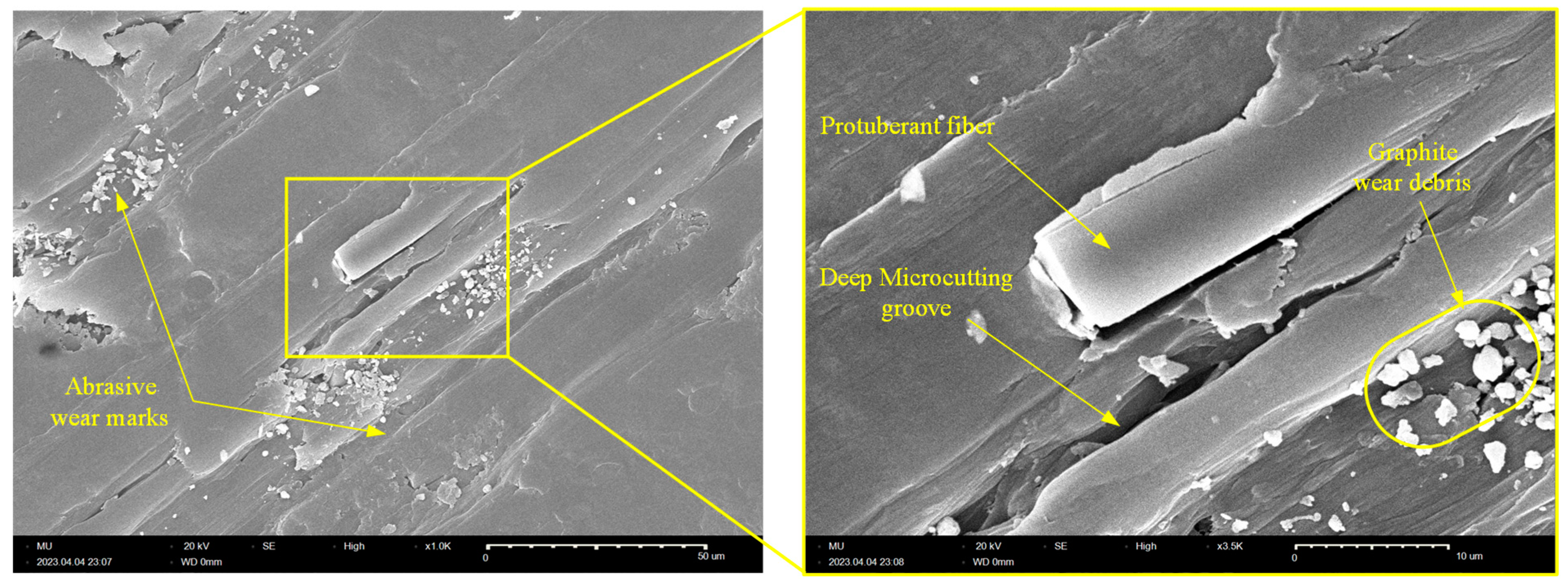
Likewise,
Figure 11 further confirms that abrasive wear is the dominant wear pattern of Z-oriented graphite-filled CFR-PA12 specimen; the tribo-surface is characterized by continuous Microcutting groove. In addition, the tribo-surface shows straightforward evidence of CF pulverization and shearing/chopping of graphite filler. Although thinning/pulverization of CFs produces further graphite powder that effectively reduces the COF and wear rate, however this comes on the expenses of frictional noise as the prolonged interaction between CFs and disc surface eventually increases the friction-induced noise of Z-oriented specimen (see
Figure 5).
Similarly,
Figure 12 shows SEM picture of the tribo-surface of X45-oriented specimen where the worn surface features clear marks of deep Microcutting grooves. Additionally, tiny graphite debris, which formed as a result of either CF crushing or shearing of graphite filler particles, are noticeable. However, the most interesting features of the tribo-surface of X45-orienetd specimen is the presence of protruded CFs and the deep Microcutting grooves; these two features were the reason behind the friction and wear characteristics of X45 specimen as the protuberant carbon fibers that are aligned parallel to sliding direction act to remove the transfer film from disc surface, hence increasing the specific wear rate of X45-oriented specimen. Further, the interaction of CF with disc surface increases the friction-induced noise as CFs are stiff amorphous material [
19]. Meanwhile, the deep Microcutting groove affirms the possibility of subsurface adhesion at either side of the cutting asperities, and hence contributes to the elevated level of frictional noise.
4. Conclusions
The present experimental study was conducted to explore the dry friction and wear characteristics of graphite-filled CFR-PA12 composite that are prepared by SLS process. The effect of part-build orientation on the tribological properties was investigated. For this purpose, the COF, contact temperature, friction-induced noise, and wear rate were measured for specimens built along 4 different orientations (X, Y, Z and X45 orientations). The experiments were conducted using pin-on-disc tribometer and scanning electron microscopy (SEM) was used to investigate the wear patterns that dominated the tribo-surfaces. The results revealed that the steady state COF, contact temperature and wear pattern of graphite-filled CFR-PA12 are orientation-independent, and that abrasive wear is the dominant wear pattern regardless of build orientation. Further, the results identified that the Z-oriented specimen possesses the highest wear resistance combined with the lowest level of frictional noise among all other orientations. Furthermore, analysis of tribo-surfaces using SEM determined that shearing of graphite inclusions and fibers thinning release graphite debris at the interface thus decreasing the COF, contact temperature, and friction-induced noise. Optical microscopy of disc surface showed that a stable transfer film was formed on the disc surface that acts to decrease the COF, surface and subsurface adhesion, and specific wear rate of Z-oriented test specimen.
However, despite the abovementioned promising features of laser-sintered graphite-filled CFR-PA12 composite, further research is needed to explore its tribological properties under a wide range of operating conditions. With this in hand, artificial intelligence can be employed to help fabricate functional bearings with customized tribological properties.
Author Contributions
Conceptualization, A.G. and S.A.A.; methodology, A.G. and S.A.A.; software, A.G. and S.A.A.; validation, A.G. and S.A.A.; formal analysis, A.G. and S.A.A.; investigation, A.G. and S.A.A.; resources, A.G. and S.A.A.; data curation, A.G. and S.A.A.; writing—original draft preparation, A.G. and S.A.A.; writing—review and editing, A.G. and S.A.A.; visualization, A.G. and S.A.A.; supervision, A.G. and S.A.A.; project administration, A.G. and S.A.A.; funding acquisition. and S.A.A. All authors have read and agreed to the published version of the manuscript.
Funding
This research was funded by the Deanship of Scientific Research at Majmaah University, grant number [R-2023-658].
Institutional Review Board Statement
Not applicable.
Data Availability Statement
The data are contained within the article.
Acknowledgments
The authors would like to thank the Deanship of Scientific Research at Majmaah University for supporting this work under project number [R-2023-658]. Also, the authors are grateful to Graphite Additive Manufacturing Ltd. (UK) for the careful preparation of test specimens.
Conflicts of Interest
The authors declare no conflict of interests.
References
- R. D. Goodridge, C. J. Tuck, and R. J. M. Hague, “Laser sintering of polyamides and other polymers,” Progress in Materials Science, vol. 57, no. 2. pp. 229–267, Feb. 2012. [CrossRef]
- M. Zhao, K. Wudy, and D. Drummer, “Crystallization kinetics of polyamide 12 during Selective laser sintering,” Polymers (Basel), vol. 10, no. 2, Feb. 2018. [CrossRef]
- L. Zárybnická, J. Petrů, P. Krpec, and M. Pagáč, “Effect of Additives and Print Orientation on the Properties of Laser Sintering-Printed Polyamide 12 Components,” Polymers (Basel), vol. 14, no. 6, Mar. 2022. [CrossRef]
- G. Yu, J. Ma, J. Li, J. Wu, J. Yu, and X. Wang, “Mechanical and Tribological Properties of 3D Printed Polyamide 12 and SiC/PA12 Composite by Selective Laser Sintering,” Polymers (Basel), vol. 14, no. 11, Jun. 2022. [CrossRef]
- S. A. Aldahash, S. A. Salman, and A. M. Gadelmoula, “Towards selective laser sintering of objects with customized mechanical properties based on ANFIS predictions,” Journal of Mechanical Science and Technology, vol. 34, no. 12, pp. 5075–5084, Dec. 2020. [CrossRef]
- K. S. Randhawa and A. D. Patel, “A review on tribo-mechanical properties of micro and nanoparticulate-filled nylon composites,” Journal of Polymer Engineering, vol. 41, no. 5. De Gruyter Open Ltd, pp. 339–355, May 01, 2021. [CrossRef]
- A. Gadelmoula and S. A. Aldahash, “Tribological Properties of Glass Bead-Filled Polyamide 12 Composite Manufactured by Selective Laser Sintering,” Polymers (Basel), vol. 15, no. 5, Mar. 2023. [CrossRef]
- S. L. Ogin, P. Brøndsted, and J. Zangenberg, “Composite materials: constituents, architecture, and generic damage,” Modeling Damage, Fatigue and Failure of Composite Materials, pp. 3–23, Jan. 2016. [CrossRef]
- A. Kausar, “Advances in Carbon Fiber Reinforced Polyamide-Based Composite Materials,” Advances in Materials Science, vol. 19, no. 4, pp. 67–82, Dec. 2019. [CrossRef]
- S. A. Aldahash and A. M. Gadelmoula, “Orthotropic properties of cement-filled polyamide 12 manufactured by selective laser sintering,” Rapid Prototyp J, vol. 26, no. 6, pp. 1103–1112, Jun. 2020. [CrossRef]
- B. Caulfield, P. E. McHugh, and S. Lohfeld, “Dependence of mechanical properties of polyamide components on build parameters in the SLS process,” J Mater Process Technol, vol. 182, no. 1–3, pp. 477–488, Feb. 2007. [CrossRef]
- L. Zárybnická, J. Petrů, P. Krpec, and M. Pagáč, “Effect of Additives and Print Orientation on the Properties of Laser Sintering-Printed Polyamide 12 Components,” Polymers (Basel), vol. 14, no. 6, Mar. 2022. [CrossRef]
- C. Yan, L. Hao, L. Xu, and Y. Shi, “Preparation, characterisation and processing of carbon fibre/polyamide-12 composites for selective laser sintering,” Compos Sci Technol, vol. 71, no. 16, pp. 1834–1841, Nov. 2011. [CrossRef]
- K. Nar, C. Majewski, and R. Lewis, “Evaluating the effect of solid lubricant inclusion on the friction and wear properties of Laser Sintered Polyamide-12 components,” Wear, vol. 522, 204873, 2023. [CrossRef]
- H. Zhang, Z. Zhang, and K. Friedrich, “Effect of fiber length on the wear resistance of short carbon fiber reinforced epoxy composites,” Compos Sci Technol, vol. 67, no. 2, pp. 222–230, Feb. 2007. [CrossRef]
- G. Srinath and R. Gnanamoorthy, “Effect of short fibre reinforcement on the friction and wear behaviour of nylon 66,” Applied Composite Materials, vol. 12, no. 6, pp. 369–383, Nov. 2005. [CrossRef]
- Y. Liu, L. Zhu, L. Zhou, and Y. Li, “Microstructure and mechanical properties of reinforced polyamide 12 composites prepared by laser additive manufacturing,” Rapid Prototyp J, vol. 25, no. 6, pp. 1127–1134, Aug. 2019. [CrossRef]
- S. Zhou, Q. Zhang, C. Wu, and J. Huang, “Effect of carbon fiber reinforcement on the mechanical and tribological properties of polyamide6/polyphenylene sulfide composites,” Mater Des, vol. 44, pp. 493–499. 2013. [CrossRef]
- A. Gadelmoula and S. A. Aldahash, “Effect of Reinforcement with Short Carbon Fibers on the Friction and Wear Resistance of Additively Manufactured PA12,” Polymers (Basel), vol. 15, no. 15, p. 3187, Jul. 2023. [CrossRef]
- K. Friedrich, “Wear of Reinforced Polymers by Different Abrasive Counterparts,” Composite Materials Series, vol. 1, no. C, pp. 233–287, Elsevier Science B.V., Netherlands. 1986. [CrossRef]
- R. Gilardi, D. Bonacchi, and M. E. Spahr, “Graphitic Carbon Powders for Polymer Applications,” in Encyclopedia of Polymers and Composites, S. Palsule, Ed., Berlin, Heidelberg: Springer Berlin Heidelberg, 2014, pp. 1–17. [CrossRef]
- Y. Meng et al., “A review of advances in tribology in 2020–2021,” Friction, vol. 10, no. 10. Tsinghua University, pp. 1443–1595, Oct. 01, 2022. [CrossRef]
- H. Unal, K. Esmer, and A. Mimaroglu, “Mechanical, electrical and tribological properties of graphite filled polyamide-6 composite materials,” Journal of Polymer Engineering, vol. 33, no. 4, pp. 351–355, Jul. 2013. [CrossRef]
- H. Wu, K. Chen, Y. Li, C. Ren, Y. Sun, and C. Huang, “Fabrication of natural flake graphite/ceramic composite parts with low thermal conductivity and high strength by selective laser sintering,” Applied Sciences (Switzerland), vol. 10, no. 4, Feb. 2020. [CrossRef]
- A. M. Gadelmoula and S. A. Aldahash, “Effects of Fabrication Parameters on the Properties of Parts Manufactured with Selective Laser Sintering: Application on Cement-Filled PA12,” Advances in Materials Science and Engineering, vol. 2019, 2019, 8404857. [CrossRef]
- N. Myshkin, A. Kovalev, D. Spaltman, and M. Woydt, “Contact mechanics and tribology of polymer composites,” J Appl Polym Sci, vol. 131, no. 3, Feb. 2014.
- Sinha Sujeet and Briscoe Brian, Polymer Tribology. Imperial College Press, 2009.
- I. M. Hutchings and P. Shipway, Tribology: friction and wear of engineering materials, Second., vol. 2nd edition. Elsevier, 2016.
- L. Chang, Z. Zhang, H. Zhang, and A. K. Schlarb, “On the sliding wear of nanoparticle filled polyamide 66 composites,” Compos Sci Technol, vol. 66, no. 16, pp. 3188–3198, Dec. 2006. [CrossRef]
- S. Bahadur, “The development of transfer layers and their role in polymer tribology,” 2000.
- J. Ye, H. S. Khare, and D. L. Burris, “Quantitative characterization of solid lubricant transfer film quality,” Wear, vol. 316, no. 1–2, pp. 133–143, Aug. 2014. [CrossRef]
- M. Rodiouchkina, J. Lind, L. Pelcastre, K. Berglund, Å. K. Rudolphi, and J. Hardell, “Tribological behaviour and transfer layer development of self-lubricating polymer composite bearing materials under long duration dry sliding against stainless steel,” Wear, vol. 484–485, Nov. 2021. [CrossRef]
- Lee Lieng-Huang, Polymer Science and Technology: Advances in polymer friction and wear, Volume 5A., vol. 5A. NEW YORK AND LONDON: PLENUM PRESS, 1974. [CrossRef]
- U. S. Tewari, J. Bijwe, J. N. Mathur, and I. Sharma, “Studies on abrasive wear of carbon fibre (short) reinforced polyamide composites,” Tribol Int, vol. 25, no. 1, pp. 53–60, 1992. [CrossRef]
- Li J. and Xia Y. C., “The reinforcement effect of carbon fiber on the friction and wear properties of carbon fiber reinforced PA6 composites,” Fibers and Polymers, vol. 10, no. 4, pp. 519–525, 2009. [CrossRef]
|
Disclaimer/Publisher’s Note: The statements, opinions and data contained in all publications are solely those of the individual author(s) and contributor(s) and not of MDPI and/or the editor(s). MDPI and/or the editor(s) disclaim responsibility for any injury to people or property resulting from any ideas, methods, instructions or products referred to in the content. |
© 2023 by the authors. Licensee MDPI, Basel, Switzerland. This article is an open access article distributed under the terms and conditions of the Creative Commons Attribution (CC BY) license (http://creativecommons.org/licenses/by/4.0/).
