
Submitted:
15 August 2023
Posted:
16 August 2023
You are already at the latest version
Abstract
This paper presents a numerical study on the vertical (axial) and lateral (flexure) behavior of CFST (Concrete-Filled Steel Tube) columns with active hoop prestress; this transverse prestressing effect is achieved by bolting together two steel half-tubes. This study refers to new construction only (i.e., no retrofit). 12 prototype CFST column specimens (segments) are analyzed. These specimens differ in the prestressing force (3 levels) and in the gravity loading ratio (4 levels); they are selected to represent typical ground columns of mid-rise buildings. The structural behavior of these column specimens is simulated with a nonlinear model implemented in Abaqus; the concrete and steel behavior are described with a damage-plasticity and a plasticity model, respectively. Finally, the interface concrete-steel interaction is represented by a hard (compression-only) surface-to-surface contact model. The calculations involve three consecutive loading steps: (i) transverse prestress, (ii) axial force, and (iii) lateral loading (shear force and bending moment). The structural behavior of the CFST columns is deeply examined and discussed; the results show that their axial-flexural capacity is adequate. Noticeably, it is concluded that the overall benefits of prestressing the columns are only modest. Preliminary studies on the aforementioned mid-rise buildings equipped with the CFST columns show that their gravity and wind capacities are largely enough; conversely, their seismic capacity is sufficient for moderate seismic ground motions only.
Keywords:
seismic behavior
; mid-rise framed buildings
; composite building columns
; concrete-filled steel tubes
; confinement effect
; active hoop prestress
1. Introduction
CFST (Concrete-Filled Steel Tube) is a composite construction technology increasingly used for columns and beam-columns of buildings and other constructions. CFST is basically an external steel tube filled with either plain or reinforced concrete. Nowadays, it is widely accepted that this solution has several relevant structural and non-structural advantages; the latter refers mainly to the fire behavior [1,2]). The structural gains have been verified both with testing [3,4,5,6,7] and numerical simulation [8,9,10,11]. Regarding structural issues, the main benefit of CFST is the confinement effect of the concrete by the steel tube; therefore, additional active hoop prestressing might provide even higher confinement. In this sense, the paper [12] numerically analyzes the performance of axially-compressed circular concrete-filled steel tubes having external hoop and longitudinal prestressing; results show that properly selected prestressing forces can provide a relevant enhancement in compressive capacity, both in terms of strength and ductility. The work [12] deals only with single short columns under centered compression; nonetheless, most actual columns also undergo relevant bending. Therefore, this paper takes a step forward, considering the joint axial and bending coupled behavior of groups of CFSTs with active hoop prestressing; the study conducted focuses only on new construction. The authors have some experience in similar fields, as one of them has carried out research on column steel jacketing for seismic retrofit of RC frame columns [13,14,15].
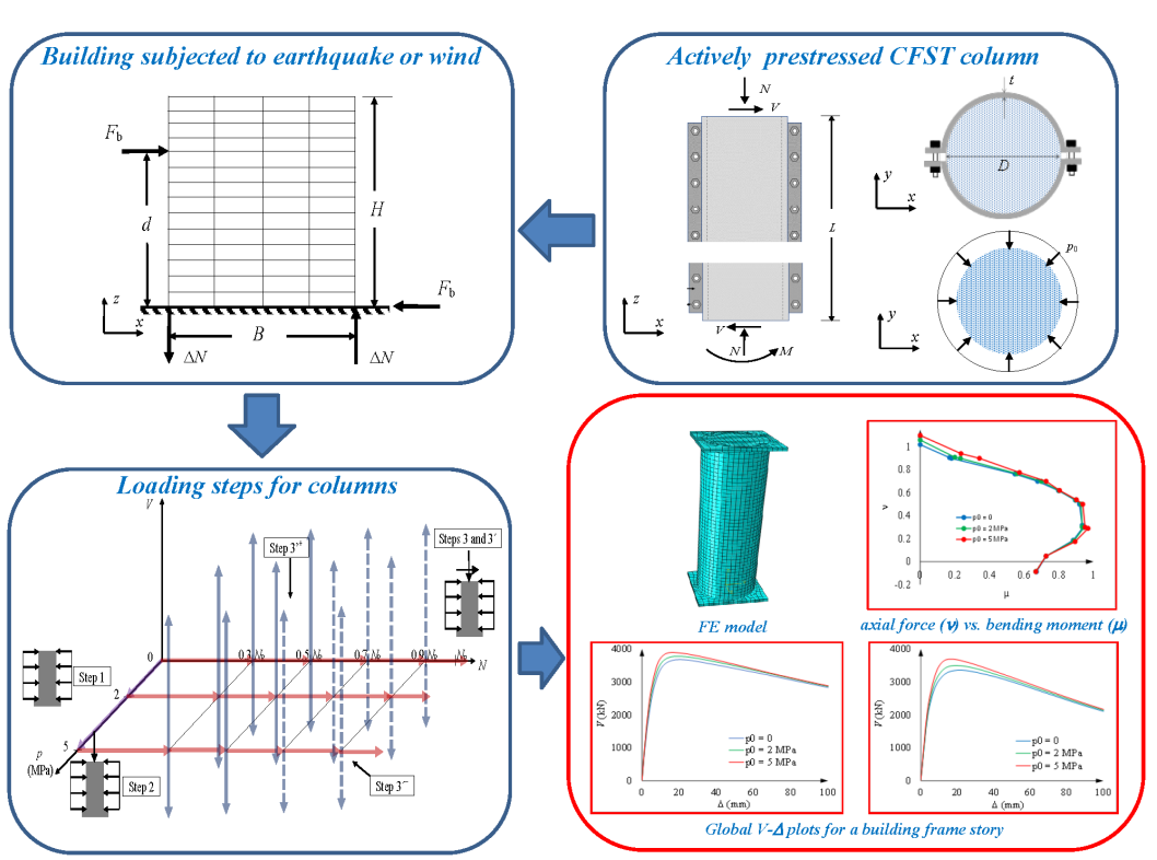
This paper numerically analyzes the structural behavior of half parts (segments) of 12 prototype building CFST columns that have active hoop prestressing and undergo axial and lateral forces. Those specimens differ in the prestressing force and gravity load ratio; are selected to represent typical ground columns of midrise buildings. The loading process is represented by three consecutive steps: transverse prestress, axial compression, and shear (lateral) force; obviously, this sequence is intended to roughly reproduce the situation in real buildings. From these results, tentative sectional interaction charts are derived. Finally, the vertical and lateral behavior of arrays of building columns (representing stories of building frames) is investigated to obtain relevant conclusions for the overall structural performance of the building.
This research is a part of a wider research effort aimed at promoting active hoop prestressing in CFST columns [12,13,14,15], mainly for buildings undergoing wind and seismic effects. Upcoming research activity will involve retrofit strategies, experimental testing, numerical parametric studies, and implementation in actual full-scale buildings [16].
2. Analyzed column segments
As discussed in section 1, the analyzed structural elements represent the lower half segment of a building column (comprised between two consecutive floors); Figure 1.b displays such full column, and Figure.c represents the aforementioned segment. In Figure 1.b, the column undergoes axial compression (N, noticeably, the upper and lower forces are alike as the column weight is neglected), shear (V), and two equal bending moments (M). As both moments are alike, in Figure 1.c, there is no bending moment in the top section of the segment (inflection point in the column middle section, where the curvature is reversed). These demanding internal forces are related through the following second-order moment equilibrium condition (Figure 1.b):
M = V L + N Δ
In equation (1), Δ is the lateral deflection of the column midsection and L is the segment length (Figure 1.b).
The column segments are considered to be clamped at their lower end (i.e., all their displacements and rotations are restrained), and free at the upper one; however, in that section, the Navier-Bernouilli condition (cross sections remain planar and orthogonal to the column axis) should hold. These boundary conditions are well suited for first-story columns, provided they are connected to a rigid foundation. For story columns, the situation is only slightly different, as the bending flexibility of the lower column and framed beams may allow some rotation in the segment lower section; hence, Δ is higher (equation (1) still applies). Therefore, although this study refers mainly to first-story columns, their conclusions can be broadly extended to story columns.
Figure 1.a and Figure 1.c present a plan view and an elevation of the column, respectively; they show that the column consists of a two-halved steel coating and a confined plain concrete (unreinforced) core. Each steel half has a curved central part and two external short vertical flat flanges, intended to hold the prestressing bolts (transversally). Therefore, the concrete core is transversally prestressed through the steel coating; the concrete-steel interaction stress (p0) is assumed to be uniformly distributed along the core perimeter, as displayed by Figure 1.d. Noticeably, simple equilibrium equations of proper steel coating parts (subsection 4.6) can relate the tensile hoop stress in the steel tube (and the forces in the bolts) to p0.
The core diameter is D = 500 mm, the steel coating thickness is t = 8 mm, the steel yield point is fy = 355 MPa, the characteristic value of the concrete compressive strength is fck = 30 MPa (C30), and the column segment height is L = 1.5 m. These values have been selected to correspond to the lower stories of most of midrise buildings (broadly speaking, between 12 and 25 floors). Apart from these common values, the analyzed cases (specimens) are distinguished by the active hoop prestress (p0) and the initial axial compression (N). The demanding axial force and bending moment are normalized with respect to their resistance values:
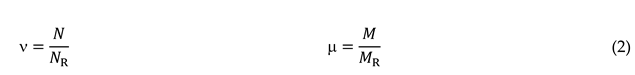
In equation(2), NR is the resisting axial force, MR is the pure moment strength (i.e., without any shear force) corresponding to zero axial force, and ν and μ are the normalized values of N and M, respectively. In this paper, ν0 refers to the initial value of ν (i.e., for V = 0, see section 3).

In equation (3), Ac is the concrete core area, α is a dimensionless parameter that accounts for the positive confinement effect of concrete and depends on its strength [17,18] (for C30 concrete, α = 2), and θ is the ratio between steel and concrete individual strengths:
In equation (4), As is the steel tube area and fy is the steel yield point. In the specimens analyzed in this paper, ; therefore, θ ≤ 1 / (α − 1)2 and, thus, the first relation in equation (3) applies:
NR = Ac fck (1 + α θ) = π × 2502 × 30 (1 + 2 × 0.7576) = 14816 kN
Analogously to ν, the normalized moment is denoted by μ and is defined as the ratio between the demanding (M) and resisting (MR) moments (equation (2)); the corresponding strength is also determined according to the Chinese regulation [17,18] as:
MR = 0.2 NR D = 0.2 × 14816 × 500 = 1482 kNm
As previously announced, different values of p0 and ν0 are considered for the analyzed specimens; the values adopted are discussed below. As for p0, three levels are taken: 0 (no hoop prestress), 2 MPa (moderate prestress), and 5 MPa (intense prestress). About ν0, 4 loading intensities are taken: 0.3 (slightly loaded column), 0.5 (intensely loaded column), 0.7 (extremely loaded column), and 0.9 (overloaded column). Table 1 displays such values of the geometric and mechanical parameters.
Table 1 shows that 3 × 4 = 12 CFST specimens are analyzed in this paper.
3. Loading steps of the column segments
As briefly discussed in section 1, the active hoop prestress (p0), axial compression (N), and lateral force (V) are applied consecutively; these three load steps are intended to reproduce the situation of columns in real buildings, as N corresponds to gravity loads and V to lateral actions. Noticeably, this sequence (p0, N and V) corresponds to new construction only; for retrofit, N should come before p0.
Regarding the lateral actions, Figure 2 displays a prototype mid-rise unbraced frame building undergoing horizontal forces (either seismic or wind-generated).
Figure 2 shows that the horizontal force Fb (base shear) is the sum (resultant) of all forces pushing on a given frame; it is located at a height d above ground level. Fb mainly generates two opposite axial forces ΔN in the external columns of the frame, while the effect on the axial forces in the inner columns can be ignored. Fb and ΔN are related by the following equilibrium condition:
Fb d = ΔN B
In equation (7), B is the horizontal separation between both extreme columns. Equation (7) shows that the ratio between Fb and ΔN is rather constant, depending mainly on the geometric characteristics of the building. Regarding the particular case depicted in Figure 2, it can be reasonably assumed that the external shear force Fb is distributed uniformly between all the columns of the frame: V = Fb / 5 (V is the column shear force due to the lateral effect). For the mid-rise buildings on which this study focusses, d ≈ 2 B; therefore, in this paper it is assumed that ΔN and V are related by:
ΔN = ± 10 V
In equation (8), the positive and negative signs correspond to the right and left columns, respectively (Figure 2). It should be kept in mind that equation (8) refers merely to a feasible and representative case.
These considerations show that, in the last loading step, the situation of the internal and external columns is different: in the internal ones only the lateral forces increase, while in the external ones both axial and lateral forces vary. Therefore, two sets of loading steps are considered in this paper:
- Internal columns. Step 1 corresponds to p0, and steps 2 and 3 to N and V, respectively.
- External columns. Steps 1 and 2 are the same than in the internal columns; regarding the last loading step, it is known as 3´, and involves variation of both N and V (these variations are represented by ΔN and V, respectively).
For further clarity, Figure 3 graphically describes such loading paths for the internal and external columns.
Figure 3 shows that loading step 1 (purple) has three possible horizontal (coaxial) branches: no load (i.e. without prestress), or reaching the p0 = 2 MPa or p0 = 5 MPa points. Then, loading step 2 consists in three parallel horizontal branches (red) starting from these points, respectively; they reach the points corresponding to ν0 = 0.3, 0.5, 0.7 or 0.9 and continue until failure. Finally, loading steps 3 and 3´ develop into 12 vertical (blue, step 3) and inclined (grey, step 3´) parallel branches that are maintained until failure. Noticeably, unlike step 3, both branches of step 3´ (upward and downward) are not symmetric; the upward one (termed next as 3´+, + sign in equation (8)) corresponds to the right external column in Figure 2, while the downward branch (termed next as 3´−, − sign in equation (8)) refers to the left column in that Figure. The loading steps depicted in Figure 3 aim to reproduce the situation of actual new buildings (or even in other constructions): step 1 corresponds to the initial prestressing (before most of the gravity loads are applied), step 2 represents the effect of gravity loads, and steps 3 and 3´ roughly reproduce the effect of lateral forces. Regarding this last effect, such forces can be extremely important (mainly in high seismicity regions); hence, steps 3 and 3´ are prolonged until collapse. It should be noted that steps 3 and 3´ for ν0 = 0.7 and 0.9 are only included for comparison purposes, as highly loaded columns are not expected in seismic areas; for this reason, these branches are indicated with dashed lines in Figure 3.
4. Numerical model of the column segments
The structural behavior of the specimens presented in section 2 is described with a model implemented in the finite element program ABAQUS 6.14-1 [19] using an implicit (standard) formulation. This software has been chosen as being highly reputable and suitable for accurately reproducing the structural behavior in complex situations; it has been considered previously by several authors for simulation of CFSTs [10,12,20].
Next subsections describe the main characteristics of the model.
4.1. Finite element mesh and boundary conditions
The finite element mesh includes the column segment itself and two fictitious (dummy) rigid steel plates (600 mm × 600 mm × 30 mm). Such plates are fixed to both segment ends to reproduce the adequate boundary conditions (bottom end clamped and top end free, although keeping the planar section condition, section 2); in this respect, the bottom plate is fixed, while the top one is free to rotate and to experience vertical and horizontal displacements.
Steel and concrete are discretized with 8-node 24-DOFs solid hexahedral (brick) elements C3D8R (Continuum, 3D, 8-node, Reduced integration) [19]; reduced integration refers to considering a single integration point in the center of the element. This element is chosen because of its accuracy (despite the reduced integration), and because shear self-locking under bending load is not likely to occur. In opposition, this element is too soft, due to the so-called hour-glassing data problem (caused by the aforementioned reduced integration); therefore, for bending, this problem can be overcome by discretizing the component (steel tube) thickness with several layers of elements.
The mesh sizes are determined through convergence studies to achieve accurate simulations with minimal increase in computational cost; the basic element size is selected as 35 mm. Figure 4 displays several views of the finite element mesh; Figure 4.c contains a general view, and Figure 4.a, Figure 4.b and Figure 4.d present detailed views of the steel tube, the concrete core and a steel plate, respectively.
Figure 4.a shows that the bolts and flanges (Figure 1.a and Figure 1.c) are not modelled, just the tube itself. Figure 4.a also shows that, to avoid hour-glassing effect, the tube thickness is discretized into three layers of elements (being 2.67 mm thick each, then), and Figure 4.d shows that two layers of elements are utilized in the plate thickness (15 mm thick each).
4.2. Concrete constitutive law
The structural behavior of in-tube (encased) concrete is totally different from the one of ordinary (uncoated) RC members, mainly due to the important confinement; as expected, the greatest effect has been found in circular columns [21]. For that reason, the average (mean) uniaxial compressive concrete behavior is described in this paper by a law that is specific for circular CFSTs [22]. Regarding tensile behavior, despite that concrete tensile stresses are anticipated (section 2), no CFST-specific tensile constitutive law has been reported (no confinement is expected in that situation); therefore, the tensile behavior is modelled according to the general purpose law in the Chinese regulation [23].
The aforementioned compressive stress-strain law consists of two segments (branches): the initial (growing) and the following (either growing or descending). These segments are described by equations (9) and (10), respectively.
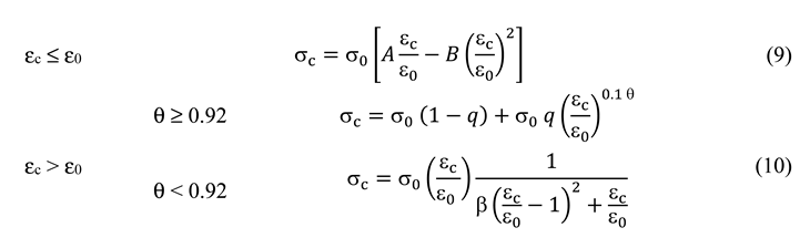
In equations (9) and (10), σc and εc are the compressive concrete stress and strain, respectively. In the first growing segment (εc ≤ ε0), σ0 is the peak stress, and ε0 is the corresponding strain; A and B are dimensionless coefficients, given by A = 2 − K and B = 1 − K, where K = 0.1 θ0.745, θ being the ratio between the steel and concrete capacities (equation (4)). In equation (9), the peak stress is Then, the corresponding strain is (stress in MPa and strain in με), where εc0 is the peak strain of plain concrete (θ = 0); it is obtained with εc0 = 1300 + 14.93 fck. The initial slope (tangent modulus of deformation) follows from E0 = σ0 A / ε0; hence, A is the ratio between the tangent and secant moduli of deformation.
Equations (10) correspond to the second segment (εc > ε0). In the top equation (θ ≥ 0.92, rather high confinement), q is an interpolation coefficient . Then, in the bottom equation (θ < 0.92, rather moderate confinement), . The top equation (10) grows continuously, but the bottom one decreases to zero, albeit slowly; this distinction is apparently aimed to reproduce the higher ductility when the confinement is more intense. In this study, θ = 0.7576 (section 2); therefore the top equation (10) must be considered.
Equation (11) describes the tensile stress-strain law:
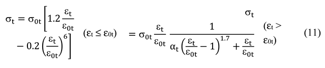
In equation (11), σ0t is the tensile peak stress; it corresponds to strain ε0t. These parameters are given by (in MPa) and (in με). Finally, αt is a dimensionless coefficient, being obtained as .
In this study, the following major values are determined: σ0 = 43.95 MPa, σ0t = 2.91 MPa, ε0 = 0.003451, and σ0 A / ε0 = 43.95 × 1.919 / 0.003451 = 24435 MPa. By using these data, Figure 5 displays the concrete compressive (Figure 5.a) and tensile (Figure 5.b) curves. Figure 5 shows that the compressive behavior is highly ductile (due to the confining effect of the steel tube), while the tensile one is quite fragile.
Concrete 3-D behavior modelling is discussed in this paragraph. Regarding initial behavior, the concrete Poisson ratio is νc = 0.18. Going into plastic behavior, the yield surface is described by parameters Kc and σb0 / σ0; Kc is the ratio between the biaxial and triaxial isobaric compressive strengths, and σb0 / σ0 is the ratio between the equi-biaxial to the uniaxial compressive maximum stress. In this paper, Kc = 2 / 3 [24] and σb0 / σ0 = 1.16 [25]. After yielding, the flow rule is characterized by the dilation angle (θ) and the eccentricity; the dilation angle is θ = 20º [26], and the eccentricity is set to 0.1 [25]. This rather unusually small dilation angle aims to compensate the fact that the confinement effect (in terms of ductility) is already taken into consideration by the highly ductile uniaxial concrete compressive constitutive law (equation (8) and Figure 5.a). Finally, the viscosity coefficient is used to adjust the constitutive law to improve the convergence efficiency in the softening stage; the assumed value is close to 0 [25].
4.3. Concrete damage plasticity model
The 3-D concrete loading-unloading behavior is represented by a CDPM (Concrete Damage Plasticity Model) [24,27,28]; as its name states, it combines plasticity and damage. The damage variables evolution is set according to a formulation specific for CFST [11]. In that work, two damage variables are defined: compressive (dc) and tensile (dt); they range between 0 (no damage) and 1 (destruction), and their evolution is set with respect the crushing () and cracking () strains, respectively. These strains are defined as the total strain minus the correspondent elastic (recovered) strain in absence of damage (when dc = dt = 0) [28]:
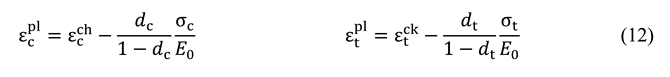
In equation (12), and are the compressive and tensile plastic strains, respectively. These equations can be solved to provide the damage variables:
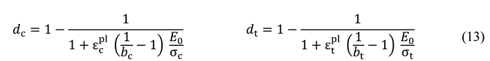
In equation (13), bc is the ratio between the plastic compressive and the crushing strains ; bt is the ratio between the plastic tensile strain and the cracking strains: . In this study, it is assumed that bc = 0.7 and bt = 0.82 [11,29]. Figure 6 displays the plots of damage variable (compressive and tensile) vs. strain.
4.4. Steel constitutive law
The tensile and compressive steel uniaxial plastic behavior of steel is described with a 5-segment stress-strain law [22]:
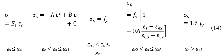
In equation (14)(14), the boundary strains are defined as εe = 0.8 fy / Es (80% of the corner yield strain), εe1 = 1.5 εe, εe2 = 10 εe1, and εe3 = 100 εe1. In the second (parabolic) segment, A, B and C are coefficients given by A = 0.2 fy / (εe1 − εe)2, B = 2 A εe1, and C = 0.8 fy + A (εe)2 – B εe.
In this study, fy = 355 MPa (Table 1) and Es = 210 GPa; then εe = 0.00135, εe1 = 0.00203, εe2 = 0.02029, and εe3 = 0.20286. From these parameters, Figure 7 displays the 5-segment curve described by equation (14).
Regarding the 3-D elastic behavior, the steel Poisson ratio is νs = 0.29. On the 3-D plastic behavior yield, the Von Mises yield criterion is employed, and the post-yield behavior is described with an isotropic strain hardening model.
4.5. Concrete-steel contact
The concrete-steel interaction at the interface between the inner core and the outer tube is described using the Abaqus surface-to-surface contact model; steel is the master surface and concrete is the slave one. The hard contact (instead of softened one) relationship is considered; this approach is compression-only (thus, bonding is neglected), and penetration is prevented. The sliding between both materials is simulated with the Mohr-Coulomb formulation using a penalty function; the friction coefficient is constant, being equal to 0.25 [30,31].
4.6. Loads application
This section describes how the loads involved in the three loading steps (Figure 3) are actually applied to the structure (Figure 4).
In step 1, the interaction initial contact pressure between concrete and steel (p0, Figure 1.d) is represented by a fictitious temperature reduction (ΔT) of the steel tube; in order to avoid undesired longitudinal axial concrete-steel interaction, the steel longitudinal thermal expansion coefficient is set equal to zero (notice that this is equivalent to having a temperature reduction “only in the transverse direction”). Given that the steel behavior is guessed to be linear in this step, the required temperature reduction can be obtained from a simple formulation: the horizontal steel tension (σs) and concrete compression (p0) are related by the equilibrium condition p0 D = 2 σs t (as announced in section 2), and the steel linear constitutive law states that σs = αs ΔT Es, where αs and Es are the steel thermal expansion coefficient and deformation modulus, respectively. By selecting αs = 10-5 ºC-1, it follows that, for p0 = 2 and 5 MPa, ΔT = −29.76 ºC and −74.41 ºC, respectively. These results have been verified comparing them with the numerical simulation using Abaqus.
In loading steps 2, 3 and 3´, the external axial (N) and shear (V) forces are applied to the upper dummy steel plate (Figure 4) as concentrated forces; as that plate is highly rigid, the effect of those forces on the real CFST tube is smoothened out sufficiently.
Finally, regarding the column self-weight, it is neglected, as being clearly lower than the external axial load.
4.7. Numerical calculation
This subsection briefs the nonlinear analyses carried out.
Geometric nonlinearity (second-order) is accounted for, since the envisaged lateral displacements (Figure 1.b) are relevant. Regarding mechanical nonlinearity, it corresponds to the constitutive laws and other issues described in subsections 4.2, 4.3, 4.4 and 4.5. The ensuing nonlinear calculations are then performed incrementally (Newton-Raphson method) using virtual time. In steps 1 and 2, the temperature (T) and axial force (N) are imposed, respectively. On the contrary, in steps 3 and 3´, the forces cannot be imposed, as negative slope in the V-Δ plot is expected, both due to the descending branches of the concrete constitutive law (Figure 5) and the simultaneous variation of N and V in step 3´ (Figure 3). Therefore, in steps 3 and 3´, the displacements are imposed instead. The initial time increment is 0.01 s, and the maximum number of iterations per step is 10000. If there is no convergence, the time step is automatically reduced to its minimum value of 0.00001 s. The convergence criterion is based on both force and displacement; the corresponding bound ratios are 0.005 and 0.01, respectively. The convergence error is 0.005.
5. Numerical results of the column segments analyses
This section presents and discusses the results of the loading steps described in section 3; subsections 5.1 through 5.4 refer to steps 1, 2, 3 and 3´, respectively. The numerical analyses are performed using the model described in section 4. It should be noted that this model cannot be calibrated with experiments, since to date no tests have been carried out with the proposed technology; the only possible corroborations are rough comparisons with simplified hand calculations and deep conceptual interpretations of the obtained results.
5.1. Loading step 1
In step 1 (concrete core prestress), the steel radial (interaction) compression generates horizontal shortening in concrete; in its turn, such strain tends to produce axial (vertical) concrete elongation. That deformation is restrained by the steel; as a result, vertical compression and tension arise in the concrete core and the steel tube, respectively. Then, a simple linear elastic calculation (by imposing the equality of the vertical strains of concrete and steel) shows that the vertical tensile stress of steel (σsz0) is equal to 15.69 and 39.23 MPa for p0 = 2 and 5 MPa, respectively; regarding concrete, the corresponding vertical compression stress (σcz0) is 1 and 2.5 MPa, respectively. These results are corroborated by the calculations with Abaqus: Figure 8 displays the sectional distribution of stress S33 (σz) in concrete (σcz) and steel (σsz). Furthermore, the points of Figure 8.c and Figure 8.d that correspond to the start of loading step 2 provide the same confirmations for concrete and steel, respectively.
Figure 8 shows that the vertical normal stresses are fairly uniformly distributed along the section (both in the concrete and steel parts); this confirms the proper reproduction of the Navier-Bernouilli hypothesis (planar sections remain planar). Regarding the longitudinal (vertical) distributions of the σcz and σsz stresses, they are also rather uniform, except for some local effects near the two dummy upper and lower end plates (Figure 4).
5.2. Loading step 2
Figure 9 displays the most meaningful and relevant results of load step 2. Figure 9.a presents the plots of normalized force vs. axial shortening (ν-w), Figure 9.b describes the variation of the concrete-steel interaction contact stress (p) with the normalized axial force (ν), and Figure 9.c and Figure 9.d exhibit, also vs. ν, the vertical axial stress of concrete (σcz) and steel (σsz), respectively.
Before analyzing the results in Figure 9 in depth, the initial slope of the ν-w plots in Figure 9.a is compared with manual calculations. Such calculations are performed according to the combination theory described in [32], and provide a vertical axial stiffness of 5994 kN/mm; this result is satisfactory, since it conforms to that of Figure 9.a (6033 kN/mm). Likewise, Figure 9.a shows that, as expected, the force capacity for the non-prestressed case (p0 = 0) corresponds approximately to ν = 1. These coincidences point out the reliability of the performed simulations; then, the remarks provided by Figure 9 are discussed in the following paragraphs. In this sense, the results are regular, predictable and compatible.
This paragraph presents, based in Figure 9, general remarks on the column segment structural behavior in step 2. Figure 9.a shows that the hoop prestress (p0) provides a positive effect, since the higher p0 is, the longer the initial near-linear branch is; moreover, the maximum force capacity is greater for higher p0. However, this effect is only moderate, since the force for w = 8 mm is approximately 7.5% larger for p0 = 5 MPa than for p0 = 0. Analogously, Figure 9.b provides similar positive remarks, as in the non-prestressed case (p0 = 0) the steel tube confines the concrete core for approximately ν ≥ 0.4 (when most needed); in the prestressed cases (p0 = 2 and 5 MPa) the prestressing is maintained continuously (except in the final collapse, for ν > 1), although it is significantly and progressively reduced as collapse approaches (mainly for p0 = 5 MPa). In other words, such a significant decrease in concrete transverse compressive stress (p) apparently precludes further increases in axial force capacity. This circumstance endorses the modelling of the prestressing effect as a “horizontal” (i.e., like a set of independent hoops) temperature reduction of the steel jacketing (subsection Error! Reference source not found.), because its representation by a constant external pressure would lead to relevant errors on the unsafe side.
Beyond the overall comments in the previous paragraph, deeper interpretations are provided below. To do this, the initial behavior (linear elastic) is analyzed; given that in loading step 2 the principal stresses directions inside the concrete core coincide with the axes in Figure 1 (more precisely, all the horizontal axes are principal), the initial values of the radial strains in concrete (throughout the core) and steel (in the inner surface of the tube) are given by:
In equations (15), subindexes r and t refer to radial and tangential directions, respectively; subindex 0 in σcz0 and σsz0 corresponds to their initial values (Figure 8). Also in equations (15), εcr and εsr represent the strain variation (shortening is positive) with respect to the initial situation (i.e., when p = p0), and σcr, σct and σcz are the actual concrete stresses (compression is positive). The top equation (15) (for concrete), has been derived by taking into consideration that, inside the core, σcr = σct = p; in the bottom equation (15) (for steel), σsr = p (compression) and σst = p (D / 2 t) (tension). Notice that, since equations (15) are linear, they require that p can take positive (compression) and negative (tension) values; Figure 9.b shows that this holds except for p0 = 0 and ν < 0.4.
Although equations (15) are derived for linear elastic behavior, the same relations still hold for higher values of the normalized axial load (however then Ec, Es, νc and νs should be replaced with the corresponding nonlinear secant values). Therefore, equations (15) can be utilized to analyze, in an approximated and unquantified way (that is, conceptually), the initial trends displayed in Figure 9. To perform this operation, it is highlighted that, except when concrete and steel are separated (this only occurs in the initial segment of the non-prestressed case, Figure 9.b) their tangential strains are equal (εct = εst); this relation provides the following expression for p:
Equation (16) is utilized next in the interpretation of the plots in Figure 9. That Figure shows that all the plots can be divided into three segments (branches): initial (linear), intermediate (moderately nonlinear), and final (more intensely nonlinear). Those segments are separated by symbols ▼ and ▲, respectively; since they correspond to the same values of ν in Figure 9.a, Figure 9.b, Figure 9.c and Figure 9.d, it is presumable that these three segments can receive common interpretations. Accordingly, next three paragraphs provide explanations for these three segments, respectively.
- Initial segments. The initial segments exhibit different characteristics in the non-prestressed and prestressed cases. In the non-prestressed case (p0 = 0), initially (that is, for small values of ν), the steel tube separates from the concrete core (i.e., εct < εst), and p remains being zero (Figure 9.b) because it cannot be negative (subsection 4.5); then, slightly before ν reaches 0.4, concrete and steel resume contact (εct = εst) and p begins to take positive values. In the prestressed cases (p0 = 2 and 5 MPa), the situation is different, as the initial value of the interaction contact stress (p) is nonzero and, thus, can decrease from the very beginning without taking negative values. These circumstances can be explained (both for the non-prestressed and prestressed cases) because the initial steel Poisson ratio is higher than that of concrete and, thus, the numerator in equation (16) is positive. For the later segments (intermediate and final) equation (16) becomes less applicable, as the behavior is nonlinear.
- Intermediate segments. Figure 9 shows three different tendencies in these segments: the linear behavior terminates (indicated by the points ▼), p increases (Figure 9.b), and the vertical axial stress is progressively transferred from concrete to steel (Figure 9.c and Figure 9.d). The first and last trends can be explained by the onset of a relevant concrete nonlinear behavior (Figure 5.a), and the growth of p is due to an increase of the concrete Poisson ratio. Regarding this last issue, concrete crushing generates significant volume expansion, resulting in an unusually high apparent Poisson ratio νc (greatly exceeding 0.5).
- Final segments. In Figure 9, the end of the intermediate segments (indicated by the points ▲) correspond to high values of ν (close to 0.8), where the steel stiffness decreases drastically (Figure 7) and, hence, most of the load is taken by the concrete (Figure 9.c and Figure 9.d). Unsurprisingly, this steel yielding causes higher axial flexibility (Figure 9.a) and less confinement (Figure 9.b).
5.3. Loading step 3
Figure 10 and Figure 11 display the force (V) vs. displacement (Δ) plots of step 3; in Figure 10 only the constitutive models in subsections 4.2 and 4.4 are considered, while in Figure 11 the concrete damage model in subsection 4.3 is also contemplated. In Figure 10 and Figure 11, the four load paths for step 3 (ν0 = 0.3, 0.5, 0.7 and 0.9, Figure 3) are plotted; however, it should be kept in mind that in seismic areas values of ν0 exceeding 0.5 are not to be presumed (indeed, cases for ν0 = 0.7 and 0.9 are included for comparison purposes only).
The maximum imposed displacements of the plots in Figure 10 and Figure 11 are selected based on two considerations: (i) they must not exceed 100 mm (in real buildings, higher displacements are not expected, as they would correspond to an interstory drift ratio near 6.67%, largely exceeding even the loosest seismic code prescriptions), and (ii) values clearly beyond the collapse points (peak of the shear force) are not totally reliable in any numerical simulation. From these considerations, the maximum displacements chosen for ν0 = 0.3, 0.5, 0.7 and 0.9, are 100, 100, 60 and 18 mm, respectively. The same values are selected for plots in Figure 13, Figure 14 (step 3’) and Figure 16 (global lateral analysis of a given building).
Figure 10 shows that, as expected, the most loaded columns (i.e., with larger ν0) exhibit less lateral force capacity; more precisely, the resistances for ν0 = 0.3 and 0.5 are rather similar, while those for ν0 = 0.7 and 0.9 are clearly smaller, particularly the latter. This trend can be explained by the combination of two quite opposite tendencies: the axial preload intensity (ν0) impairs the column capacity to resist lateral forces (V), but moderate values of ν0 can provide a rather beneficial effect, similar of that of axial prestressing in RC beams. Regarding the influence of the active prestress (p0), it is more intense for greater values of ν0; the percentages of increase for p0 = 5 MPa compared to p0 = 0 are approximately 4.6% (ν0 = 0.3), 8.4% (ν0 = 0.5), 16.3% (ν0 = 0.7) and 48.9% (ν0 = 0.9). This tendency can be explicated because in the initial situation (i.e., for V = 0), the difference between the cases for p0 = 0, 2 and 5 MPa is greater for higher values of ν0; this circumstance is highlighted by Figure 9.a. In other words, apparently, the benefit of the active transverse prestressing is not generated during step 3, but it rather is a continuation of the advantage produced through step 2.
Figure 11 reveals similar trends to Figure 10; regarding the influence of the prestress, the increase percentages for p0 = 5 MPa with respect to p0 = 0 are approximately 5.8% (ν0 = 0.3), 11.4% (ν0 = 0.5), 34.2% (ν0 = 0.7) and 335% (ν0 = 0.9). About this tendency, the same explanation than in Figure 10 (based on Figure 9.a) still holds. On the other hand, comparison between Figure 10 and Figure 11 shows that, unsurprisingly, the consideration of the concrete damage model (subsection 4.3) has a significant impact. More precisely, in Figure 11 there is a reduction in the maximum capacity of lateral force; also unsurprisingly, this reduction is higher for larger values of ν0 (as the damage is higher). Finally, Figure 11.d shows that in the most axially loaded specimen (ν0 = 0.9), the initial stiffness of the non-prestressed case is smaller than those of the prestressed ones. This indicates that the lack of active prestressing corresponds to the initial nonlinear behavior (i.e., for V = 0) of the analyzed structural element; the absence of this effect in Figure 10.d shows that it only occurs when the concrete damage model is taken into consideration.
For greater clarity, Figure 12 displays plots of compressive and tensile vertical stresses for concrete (σcz and σtz, respectively) and steel (σsz) at the extreme left and right fibers (points) of the bottom section of the analyzed column segment; those points are represented in Figure 12 as ● and , respectively. These magnitudes are plotted in Figure 12 against the lateral demanding force (V). Figure 12.a through Figure 12.d correspond to ν0 = 0.3, 0.5, 0.7 and 0.9, respectively. Figure 12.a and Figure 12.b correspond to ν0 = 0.3, and Figure 12.c and Figure 12.d to ν0 = 0.9. In all these Figures, the negative sign corresponds to compression.
Figure 12 presents regular and predictable results; in this sense, the plots of Figure 12 are a continuation of those of step 2 (Figure 9). More specific considerations are discussed next.
- Vertical stress of concrete and steel for ν0 = 0.3. The behavior described by Figure 12.a and Figure 12.b agrees with Figure 11.a. More specifically,Figure 12.a and Figure 12.b show that the initial behavior is linear, and then, for approximately V = 300 kN, the tensile concrete stress (σtz) reaches its maximum capacity; this stress is progressively taken by steel, thus generating an increase of the concrete compressive stress is also generated. Figure 12.a shows that the concrete compressive stress reaches extraordinarily high values, clearly above σ0 (Figure 5); this circumstance highlights the importance of the steel confinement, being this effect rather independent of the hoop prestress. In Figure 12.b, points marked with ■ correspond to the steel yielding.
- Vertical stress of concrete and steel for ν0 = 0.9. Figure 12.c and Figure 12.d provide rather similar remarks than Figure 12.a and Figure 12.b (for ν0 = 0.3); perhaps the main differences lie in the fact that concrete is always under compression, and the steel branches for points ● and are asymmetric due to early steel yielding at point .
5.4. Loading step 3’
Analogously to Figure 11 (for step 3), Figure 13 and Figure 14 display the force (V) vs. displacement (Δ) plots of steps 3´+ and 3´−, respectively. To understand the plots of Figure 13 and Figure 14, it should be kept in mind that in Figure 13 they correspond to simultaneous increase of V and N (positive sign in equation (8)), while in Figure 14 the opposite situation occurs (N decreases as V increases, negative sign in equation (8)).
Figure 13 shows a regular and anticipated behavior; comparison with Figure 11 shows that the aforementioned increase of the axial force has led to a significant decrease of the shear force capacity. Unsurprisingly, the higher the initial force (ν0), the more intense the reduction. Figure 13.d indicates that the initial nonlinear behavior shown by Figure 11.d extends also to the case p0 = 2 MPa.
To better understand the results displayed in Figure 14, the final approximate values (i.e., for the maximum imposed displacement) approximate values of the axial force in the left columns are presented next (equation (8)): N = −1295 kN (Figure 14.a), N = +727 kN (Figure 14.b), N = +2607 kN (Figure 14.c), and N = +4327 kN (Figure 14.d); negative values indicate tension. In general terms, the results in Figure 14 are consistent and likely. Comparison with Figure 13 indicates an important increase in shear capacity, mainly for highly loaded columns (except, perhaps, for ν0 = 0.9); in this sense, unlike Figure 11 and Figure 13, the shear capacity is higher for the specimen with the greatest initial compression (Figure 14.d). On the other hand, the influence of the active hoop prestress has almost disappeared (with the exception of ν0 = 0.9); this circumstance can be explained by the predominance of forces near zero or tensile. Finally, the ductility is significantly higher than in any other comparable situation (Figure 11 and Figure 13); seemingly, it is due to the virtual absence of second-order effects (or even positive effect for tensile forces). Regarding this trend, it should be kept in mind that plots in Figure 14.c and Figure 14.d are deliberately interrupted for consistency with the corresponding plots in Figure 11 and Figure 13.
6. Column section capacity
This section utilizes results of the loading steps 2, 3 and 3´ (section 5) to estimate the structural capacity of the column sections; results are presented in Figure 15 as interaction charts, that is, diagrams of normalized axial force (ν) vs. bending moment (μ) (equation (2)) for each value of p0 (0, 2 or 5 MPa). These charts are generated by joining the thirteen end points (i.e., section capacity) of the plots in Figure 9.a, Figure 11, Figure 13 and Figure 14; such points are represented in Figure 15 with symbols ◯, ■, ▲ and ▼, respectively. Figure 9.a (loading step 2, Figure 3) corresponds to μ = 0 (no bending); the ordinate is the ultimate value of ν (for w = 8 mm). In Figure 11 (loading step 3, Figure 3), obviously, the ordinate values are ν = 0.3, 0.5, 0.7 and 0.9; the abscissae are obtained from the second-order equilibrium equation (1) using the maximum (ultimate) value of Δ in the corresponding V-Δ plots in Figure 11. In Figure 13 and Figure 14 (loading steps 3’+ and , respectively), the values of ν are determined by integration of the normal vertical stresses of concrete and steel along the column section; the abscissae are obtained similarly as in Figure 11. Notice that second-order effects cause that the maximum values of shear force V do not always coincide with the maxima of moment M.
Figure 15 shows that, as expected, the influence of p0 is higher for large values of ν (and small values of μ, then) than in the opposite situation (ν ≈ 0); more precisely, in that case, the influence of p0 is practically negligible. Figure 15 also shows that the section capacity is not highly sensitive to the loading path, as the chart points arising from load steps 3 and 3’ (for the same value of p0) are either close to each other or belong to one of the rather smooth ν-μ interaction diagrams plotted in Figure 15. On the other hand, in the diagram for p0 = 0, unsurprisingly, μ = 0 corresponds to ν ≈ 1; however, when ν = 0, then μ ≈ 0.7. This last apparent inconsistency can be explained by the influence of the shear force in the moment strength, since μ refers to the pure moment strength MR (equation (2)).
7. Global structural behavior of the building
This section uses the results in sections 5 and 6 to expose a brief preliminary assessment of the structural capacity of a representative mid-rise unbraced frame building (such as the one in Figure 2) equipped with CFST columns. This study consists in analyzing the performance of a given story in two different situations: gravity loads only (load step 2, subsection 5.2), and lateral pushing forces as well (load steps 3 and 3’, subsections 5.3 and 5.4); these cases are discussed in subsections 7.1 and 7.2, respectively. In both situations, the vertical and lateral story behavior is modelled as a parallel combination of the column specimens analyzed in sections 2, 3, 4 and 5.
7.1. Story vertical behavior
The load distribution between the columns of a typical story of a mid-height building is almost independent on their axial stiffness, being more related to the slab flexural behavior. Therefore, the story vertical capacity can be approximately estimated by adding those of each individual column (Figure 9.a); in other words, the remarks exposed from that Figure (mainly in terms of axial force capacity) can be applied almost directly to the building overall behavior under gravity loads. Given these considerations, the obvious final conclusion is that a proper design of the CFST columns can lead to a satisfactory vertical load capacity of the building story.
7.2. Story lateral behavior
This subsection presents a numerical study about the joint shear behavior of the 5 columns of a given story of the 2-D prototype building frame in Figure 2. The behavior of the left (façade) column corresponds to loading step 3´− (subsection 5.4, Figure 14), the 3 inner columns are associated with loading step 3 (subsection 5.3) and the right (façade) column is consistent with loading step 3´+ (subsection 5.4, Figure 13). Cases ν0 = 0.7 and ν0 = 0.9 are omitted, since they are highly unfeasible in seismic regions, as discussed after Figure 3.
Before performing the announced numerical study, the demanding shear forces during wind or seismic excitations in actual situations are estimated next in order to assess the relevance of the building lateral strength. In both cases the dynamic effect is represented by static forces, and their approximate values are derived from simplified code-type calculations.
- Wind. The horizontal shear force on a bottom story of a 2-D frame ranges approximately between 180 kN (12 stories, covered situation, span length 5 m, story height 3 m) and 1125 kN (25-story building, exposed situation, span length 8 m, story height 4.5 m).
- Earthquakes. The equivalent static lateral force method shows that, for typical columns of mid-rise buildings (building fundamental period lying in the design spectrum plateau), the base shear force (V) ranges approximately between 0.4 ag W (rock-like soil, ordinary use, high response modification factor) and ag W (soft soil, essential use, moderate response modification factor), where W is the supported seismic weight (equal to the sum of the demanding axial forces N of each column) and ag is the seismic acceleration (corresponding to rock and 475 years return period) referred to the gravity acceleration (also commonly known as PGA, Peak Ground Acceleration). These considerations show that, for ν0 = 0.3, in a high seismicity area (ag = 0.4 g) the demanding base shear force for a 5-column frame like the one depicted by Figure 2 ranges between 3600 and 9000 kN; in a low seismicity area (ag = 0.1 g), such bounds become 900 and 2250 kN, respectively. Obviously, for ν0 = 0.5, these values must be multiplied by 5 / 3; the ranges are 6000-15000 kN (for ag = 0.4 g) and 1500-3750 kN (for ag = 0.1 g). It should be kept in mind that these lateral forces must be combined with the vertical ones that correspond to the seismic weight.
The results of the announced numerical study are presented and discussed next. Figure 16 displays the shear force (V) vs. lateral displacement (Δ) plots of the bottom 5-column 2-D frame story of the building depicted in Figure 2. Assuming that the beams are infinitely rigid in their axial direction, these story V-Δ plots are approximately obtained by adding those of the individual column segments (Figure 11, Figure 13 and Figure 14 for the central, right and left columns in Figure 2, respectively). Notice that Δ represents the displacement of a half-column segment, while the interstory drift is actually 2 Δ (Figure 1.b).
Figure 16 shows that the story shear capacity is rather sufficient to resist moderate seismic events (approximately corresponding to PGA = 0.2 g); it should be kept in mind that, as the considered demanding seismic forces have been divided by a rather high response modification factor, significant damage (both structural and nonstructural) is to be expected. Figure 16 also points out that the benefit provided by the active hoop prestressing is only moderate; this circumstance is predictable, given the information provided by Figure 11, Figure 13 and Figure 14. Regarding ductility, plots in Figure 16 seem to indicate quite satisfactory displacement ductility. In relation to wind, the story shear capacity is largely enough in all the cases analyzed.
8. Conclusions
This paper assesses numerically the vertical and lateral structural performances of CFST (Concrete-Filled Steel Tube) columns that are actively prestressed transversely by bolting together two steel half-tubes; the study refers to new construction only. Representative prototype CFST column specimens (segments) are analyzed; they differ in their prestressing force and gravity loading ratio. The nonlinear structural static behavior of the column specimens is simulated with a model implemented in Abaqus. The obtained results provide the following major conclusions on the CFST columns performance (sections 5 and 6):
- Vertical loads (axial force). As expected, the strength of CFST columns for vertical centered axial compression is significant (subsection 5.2). The benefit of the active hoop prestress is relevant, although not outstanding; this circumstance can be explained by the tube transverse expansion (due to Poisson effect) that impairs the concrete core confinement (although not cancelling it totally).
- Lateral forces (bending). Also as expected, the bending strength of CFST columns is significant (subsections 5.3 and 5.4). The benefits of the active hoop prestress are smaller than for the axial load; this trend is seemingly due to the lack of sectional global lateral expansion during bending.
- Axial force-bending moment interaction. The strength for eccentric axial loads is pretty high; for moderate compression, the moment capacity is clearly higher than for pure bending (section 6). The influence of the active transverse prestress is higher for large axial compression; for pure bending and for axial tension, that influence is practically negligible.
The results on the CFST columns are extended to make available preliminary estimates on the gravity, wind and seismic performance of mid-rise (roughly, between 12 and 25 floors) unbraced frame buildings equipped with such elements (section 7):
- Gravity loads. Given the notable axial capacity of the CFST columns, a proper design can make available a satisfactory vertical strength.
- Lateral forces (wind and seismic). The story shear capacity provided by CFST columns is sufficient for moderate seismic ground motions (approximately, Peak Ground Acceleration 0.2 g). This conclusion refers to a rather high response modification factor; therefore, the columns would be significantly damaged, and, thus, high ductility is required. Regarding this last issue, the displacement ductility is rather satisfactory. Finally, about wind, the story shear strength is largely enough.
Further research includes numerical analysis of retrofit strategies, experiments on the proposed active transverse prestressing technique, wider numerical parametric studies, and implementation in actual full-scale buildings. The results of the experiments are expected to allow calibration of the column segments numerical model.
Author Contributions
Conceptualization, A.A.; methodology, F.L.-A.; software, X.H.; validation, F.L.-A.; formal analysis, F.L.-A.; investigation, X.H.; resources, X.H.; data curation, X.H.; writing—original draft preparation, F.L.-A.; writing—review and editing, F.L.-A., A.A. and X.B.; visualization, F.L.-A.; supervision, A.A.; project administration, X.H.; funding acquisition, X.H. and X.B. All authors have read and agreed to the published version of the manuscript.
Funding
This research has been partially funded by the Spanish Research Agency (AEI) of the Ministry of Science and Innovation (MICIN) through project with reference: PID2020-117374RB-I00 / AEI / 10.13039/501100011033. The stay of Prof. Xiao Hu in Barcelona was funded by the State Key Laboratory of Geohazard Prevention and Geoenvironment Protection of China (Grant No. SKLGP2020K010). The study of Mr. Xiangbo Bu in the Technical University of Catalonia (UPC-BarcelonaTech) is funded by the Chinese Government Scholarship (CSC No. 201906560013). These supports are gratefully acknowledged.
Conflicts of Interest
The authors declare no conflict of interest.
Appendix A. List of symbols
A, B, C: Dimensionless parameters in equation (14).
A, B, K: Dimensionless parameters in equation (9).
Ac / As: Area of the concrete core / steel tube.
ag: Seismic acceleration (corresponding to rock and to 475 years return period).
B: Building width (Figure 2 and equation (7)).
bc / bt: Ratio between the compressive plastic and crushing strains / tensile plastic and cracking strains.
D: Diameter of the concrete core (Figure 1.a).
d: Height of the resultant of the lateral forces on a building (Figure 2 and equation (7)).
dc / dt: Compressive / tensile damage variables.
E0: Initial (tangent) modulus of deformation of concrete.
Es: Steel modulus of elasticity.
Fb: Base shear force (Figure 2 and equation (7)).
fck: Characteristic value of the concrete compressive strength.
fy: Steel yield point.
g: Gravity acceleration.
H: Clear height of the building column (L = H / 2, Figure 1.b).
Kc: Ratio between the concrete biaxial and triaxial isobaric compressive strengths.
L: Length (height) of the column segment (L = H / 2, Figure 1.b).
leq: Mesh size.
M: Demanding bending moment (Figure 1.c).
MR: Column moment strength corresponding to zero axial force (equation (6)).
N: Demanding compressive axial force (Figure 1.c).
NR: Column axial strength (equation (3)).
p: Concrete-steel normal contact interaction stress (Figure 9.b).
p0: Active hoop prestress (Figure 1.d).
q: Dimensionless parameter in equation (10).
T: Temperature (ΔT: Variation of temperature).
t: Thickness of the steel coating (Figure 1.a).
V: Demanding shear force (Figure 1.c).
W: Supported seismic weight (equal to the demanding axial force N).
w: Vertical displacement of the columns segment top section.
α: Dimensionless parameter in equation (3) that depends on the concrete strength.
αs: Steel longitudinal thermal expansion coefficient.
αt: Dimensionless parameter (equation (11)).
β: Dimensionless parameter in equation (10).
Δ: Lateral displacement of the columns segment top section (Figure 1.b).
ΔN: Variation of the axial force on the external columns a building (Figure 2 and equations (7) and (8)).
εc0: Maximum plain concrete strain (equation (9)).
Crushing / cracking / plastic strains.
μ: Normalized demanding bending moment (equation (2)). Friction coefficient.
ν0 / ν: Initial axial compression / normalized demanding axial force (equation (2)).
νc / νs: Steel / concrete Poisson ratio.
θ: Ratio between the steel and concrete strengths (equation (4)). Dilation angle.
σc / εc / σt / εt: Compressive and tensile concrete axial stress / strain. Additional subindexes r (radial), t (tangential) and z (vertical) refer to the directions (equation (15)); subindex 0 indicates initial value (in σcz0).
σs / εs: Steel axial stress / strain. Subindexes r (radial), t (tangential) and z (vertical) refer to the directions (equation (15)); subindex 0 indicates initial value (in σsz0).
σ0 / ε0: Compressive axial concrete peak stress / corresponding strain (equations (9) and (10)).
σb0: Equi-biaxial maximum compressive stress.
σ0t / ε0t: Tensile axial concrete peak stress / corresponding strain (equation (11)).
References
- Romero, M.L.; Moliner, V.; Espinos, A.; Ibañez, C.; Hospitaler, A. Fire behavior of axially loaded slender high strength concrete-filled tubular columns. J. Constr. Steel Res. 2011, 67, 1953–1965. [Google Scholar] [CrossRef]
- Zhou, K.; Han, L.-H. Experimental performance of concrete-encased CFST columns subjected to full-range fire including heating and cooling. Eng. Struct. 2018, 165, 331–348. [Google Scholar] [CrossRef]
- Portolés, J.; Romero, M.; Bonet, J.; Filippou, F. Experimental study of high strength concrete-filled circular tubular columns under eccentric loading. J. Constr. Steel Res. 2011, 67, 623–633. [Google Scholar] [CrossRef]
- Hajjar JF, Denavit MD, Perea T, Leon RT. 2012. Seismic design and stability assessment of composite framing systems. 9th International Conference on Urban Earthquake Engineering. Tokyo, Japan.
- Ekmekyapar, Al-Eliwi BJM. 2016. Experimental behavior of circular concrete filled steel tube columns and design specifications. Thin-Walled Structures. 105:220-230.
- Wang, J.; Sun, Q.; Li, J. Experimental study on seismic behavior of high-strength circular concrete-filled thin-walled steel tubular columns. Eng. Struct. 2019, 182, 403–415. [Google Scholar] [CrossRef]
- Tao, Z.; Hasan, M.; Han, D.; Qin, Q.; Ghafar, W.A. Study of the Axial Compressive Behaviour of Cross-Shaped CFST and ST Columns with Inner Changes. Buildings 2023, 13, 423. [Google Scholar] [CrossRef]
- Ouyang, Y.; Kwan, A.; Lo, S.; Ho, J. Finite element analysis of concrete-filled steel tube (CFST) columns with circular sections under eccentric load. Eng. Struct. 2017, 148, 387–398. [Google Scholar] [CrossRef]
- Hajjar JF, Schiller PH. Molodan A. 1998. A distributed plasticity model for concrete-filled steel tube beam-columns with interlayer slip. Engineering Structures. 20(8):663-676.
- Albareda-Valls, A. 2013. Numerical analysis of concrete-filled tubes with stiffening plates under large deformation axial loading. Ph.D. Dissertation, Polytechnic University of Catalonia (UPC), Barcelona.
- Du GF, Bie MX. 2016. Numerical simulation of axial compression mechanical behavior of CFST column with concrete damaged plasticity (in Chinese). Journal of Shenyang Jianzhu University (Natural Science). 32(3):444-451.
- Milan, C.C.; Albareda-Valls, A.; Carreras, J.M. Evaluation of structural performance between active and passive preloading systems in circular concrete-filled steel tubes (CFST). Eng. Struct. 2019, 194, 207–219. [Google Scholar] [CrossRef]
- Hu X, Yongjiu Q. 2013a. Experiment study of reinforced concrete short column strengthened by circular steel tube under axial loading (in Chinese). Sichuan Building Science. 39(6):96-98.
- Hu X, Yongjiu Q. 2013b. Compressive behavior of reinforced concrete short column strengthened by circular steel tube under axial compressing (in Chinese). Journal of Highway and Transportation Research and Development. 30(6):100-108.
- Hu X. 2015. Research on compressive performance and bearing capacity of RC short columns strengthened with circular steel jacketing (in Chinese). PhD Thesis. Southwest Jiaotong University.
- Swami, G.; Thai, H.-T.; Liu, X. Structural robustness of composite modular buildings: The roles of CFST columns and inter-module connections. Structures 2023, 48, 1491–1504. [Google Scholar] [CrossRef]
- Cai, SH. 2003. Modern steel confined concrete structures (in Chinese). China Communication Press.
- CECS 28-90. 1992. Specification for design and construction of concrete-filled steel tubular structures (in Chinese). China Association for Engineering Construction Standardization.
- Smith, M. 2009. ABAQUS/Standard User's Manual, Version 6.9. Providence, RI: Dassault Systèmes Simulia Corporation.
- Sarir, P.; Jiang, H.; Asteris, P.G.; Formisano, A.; Armaghani, D.J. Iterative Finite Element Analysis of Concrete-Filled Steel Tube Columns Subjected to Axial Compression. Buildings 2022, 12, 2071. [Google Scholar] [CrossRef]
- Susantha, K.; Ge, H.; Usami, T. Uniaxial stress–strain relationship of concrete confined by various shaped steel tubes. Eng. Struct. 2001, 23, 1331–1347. [Google Scholar] [CrossRef]
- Han LH, Feng J. 1995. The constitutive model of concrete and its application in numerical analysis of CFST (in Chinese). Journal of Harbin University of Architecture and Engineering. 28(5):26-32.
- GB 50010. 2010. Code for Design of Concrete Structures (in Chinese). China.
- Lubliner J, Oliver J, Oller S, Oñate E. 1989. A plastic-damage model for concrete. International Journal on Solids and Structures. 25(3):299-326.
- Hibbitt D, Karlson B, Sorensen P. 2003. ABAQUS Version 6.4: Theory manual, users’ manual, verification manual and example problems manual. Hibbitt, Karlson and Sorensen Inc.
- Long, X. 2014. Experimental and numerical investigations on concrete-filled steel tubular stub columns under axial compression (in Chinese). Master Degree Thesis. Hunan University.
- Lee, J.; Fenves, G.L. Plastic-Damage Model for Cyclic Loading of Concrete Structures. J. Eng. Mech. 1998, 124, 892–900. [Google Scholar] [CrossRef]
- Alfarah, B.; López-Almansa, F.; Oller, S. New methodology for calculating damage variables evolution in Plastic Damage Model for RC structures. Eng. Struct. 2017, 132, 70–86. [Google Scholar] [CrossRef]
- Zhang J, Wang QY, Hu S, Wang C. 2008. Parameters verification of concrete damaged plastic model of ABAQUS (in Chinese). Building Structure. 38(8):127-130.
- Srinivasan, C.N.; Schneider, S.P. Axially Loaded Concrete-Filled Steel Tubes. J. Struct. Eng. 1999, 125, 1202–1206. [Google Scholar] [CrossRef]
- Hu, H.-T.; Huang, C.-S.; Wu, M.-H.; Wu, Y.-M. Nonlinear Analysis of Axially Loaded Concrete-Filled Tube Columns with Confinement Effect. J. Struct. Eng. 2003, 129, 1322–1329. [Google Scholar] [CrossRef]
- Zhong, ST. 2006. Unified theory for CFST (in Chinese). Tsinghua University Press.
Figure 1.
Analyzed CFST with active preloading.
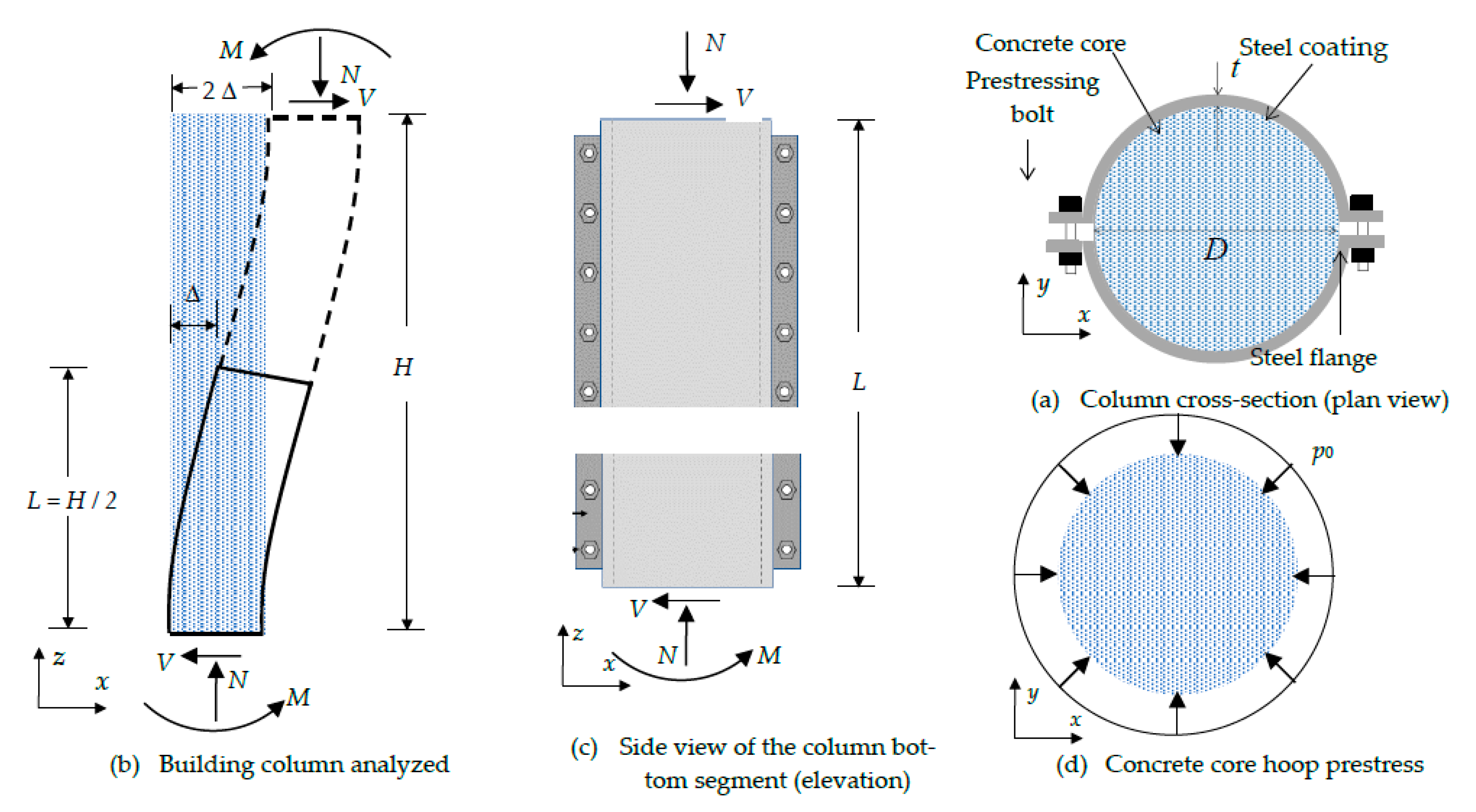
Figure 2.
Relation between the lateral force (Fb) on the axial forces (ΔN) of the building columns.
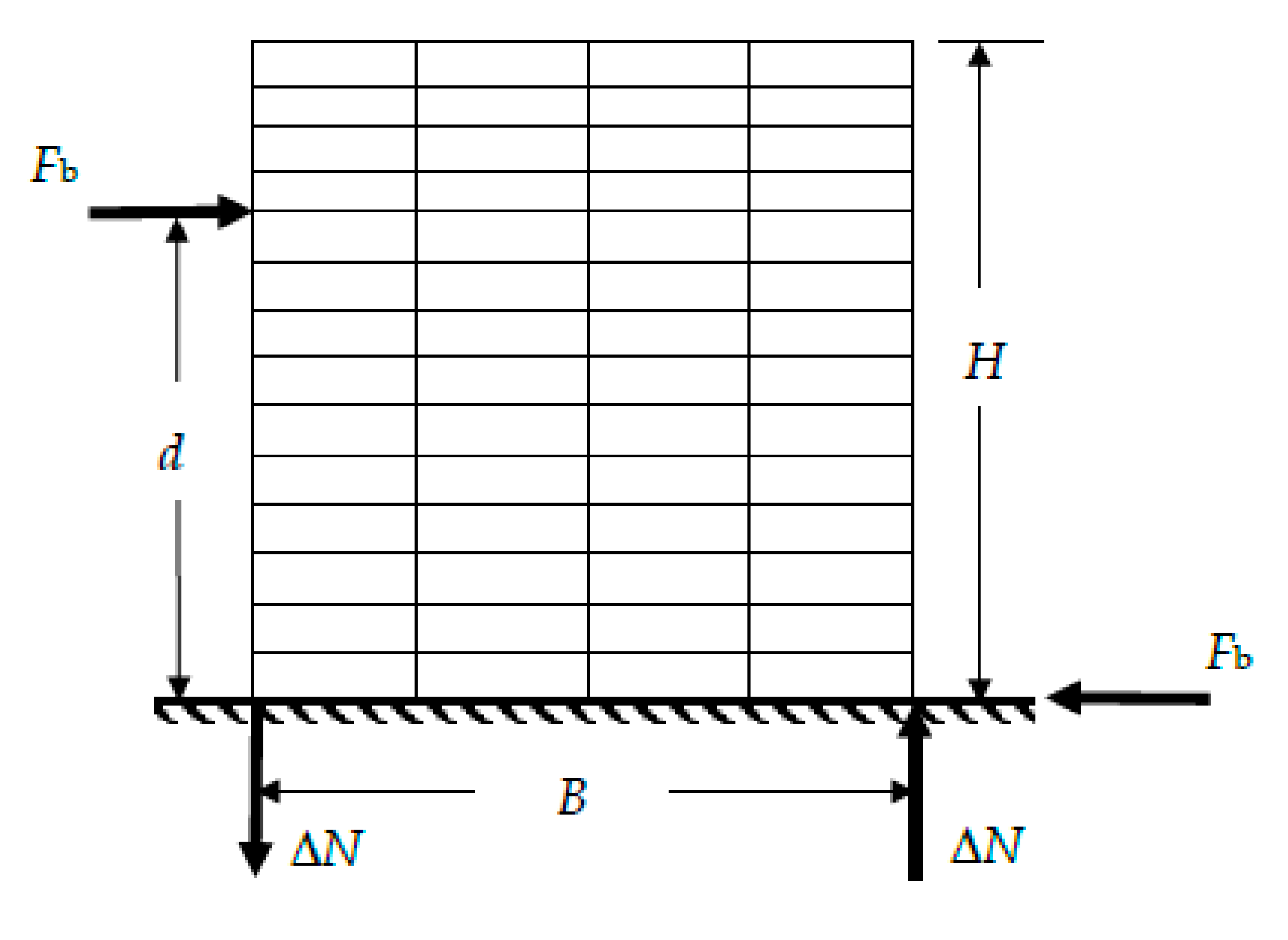
Figure 3.
Loading steps for internal columns (steps 1, 2 and 3) and external columns (steps 1, 2 and 3´) (Figure 2).
Figure 3.
Loading steps for internal columns (steps 1, 2 and 3) and external columns (steps 1, 2 and 3´) (Figure 2).
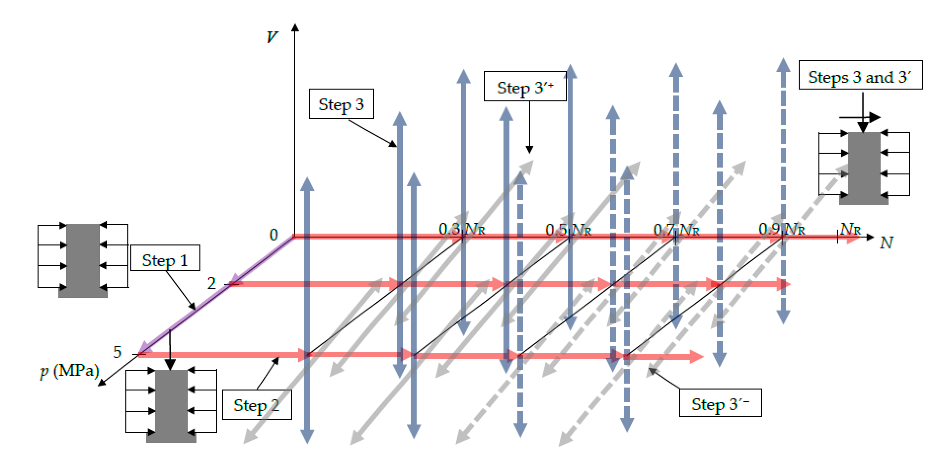
Figure 4.
Finite elements meshes.
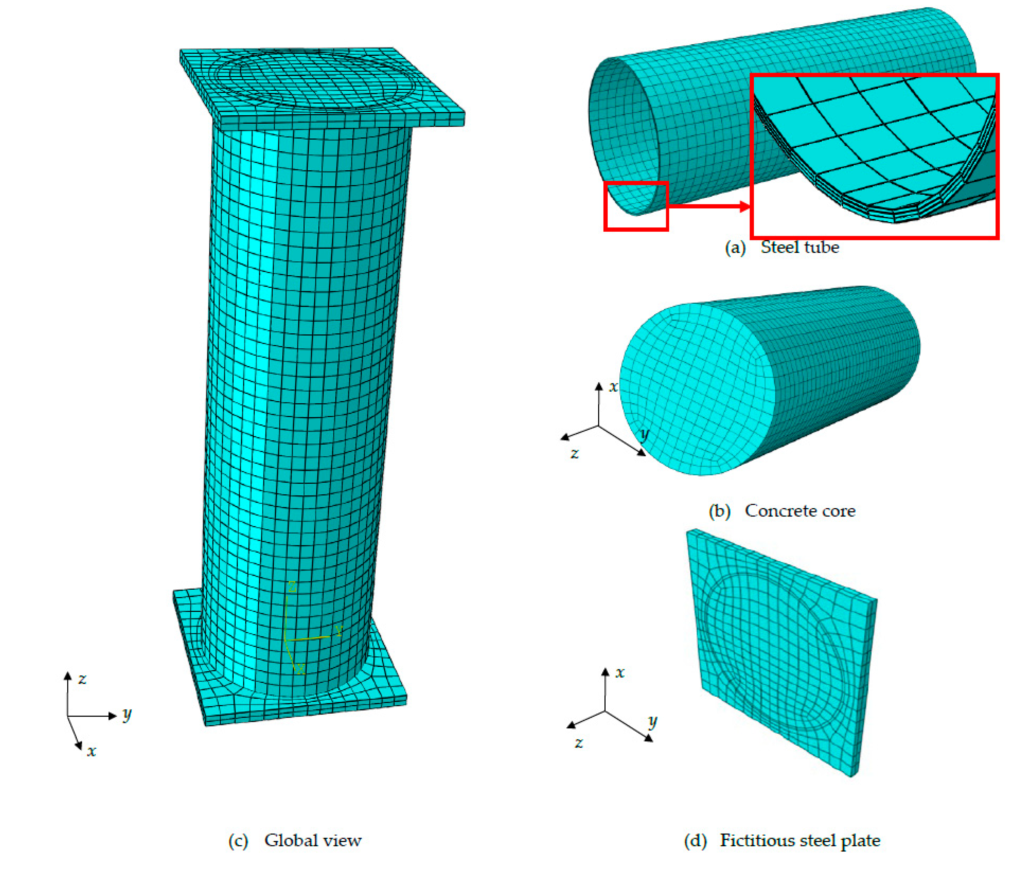
Figure 5.
Uniaxial (compressive and tensile) concrete constitutive stress-strain laws.
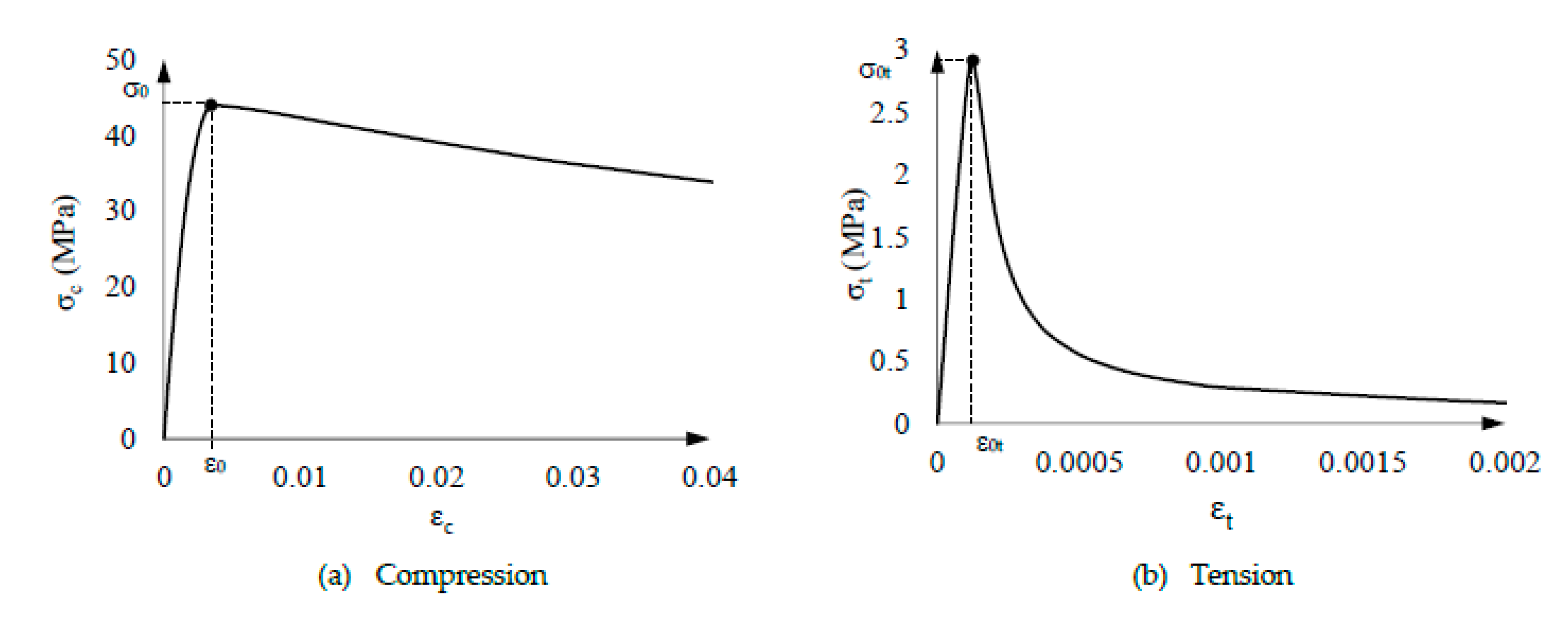
Figure 6.
Damage variables evolution.
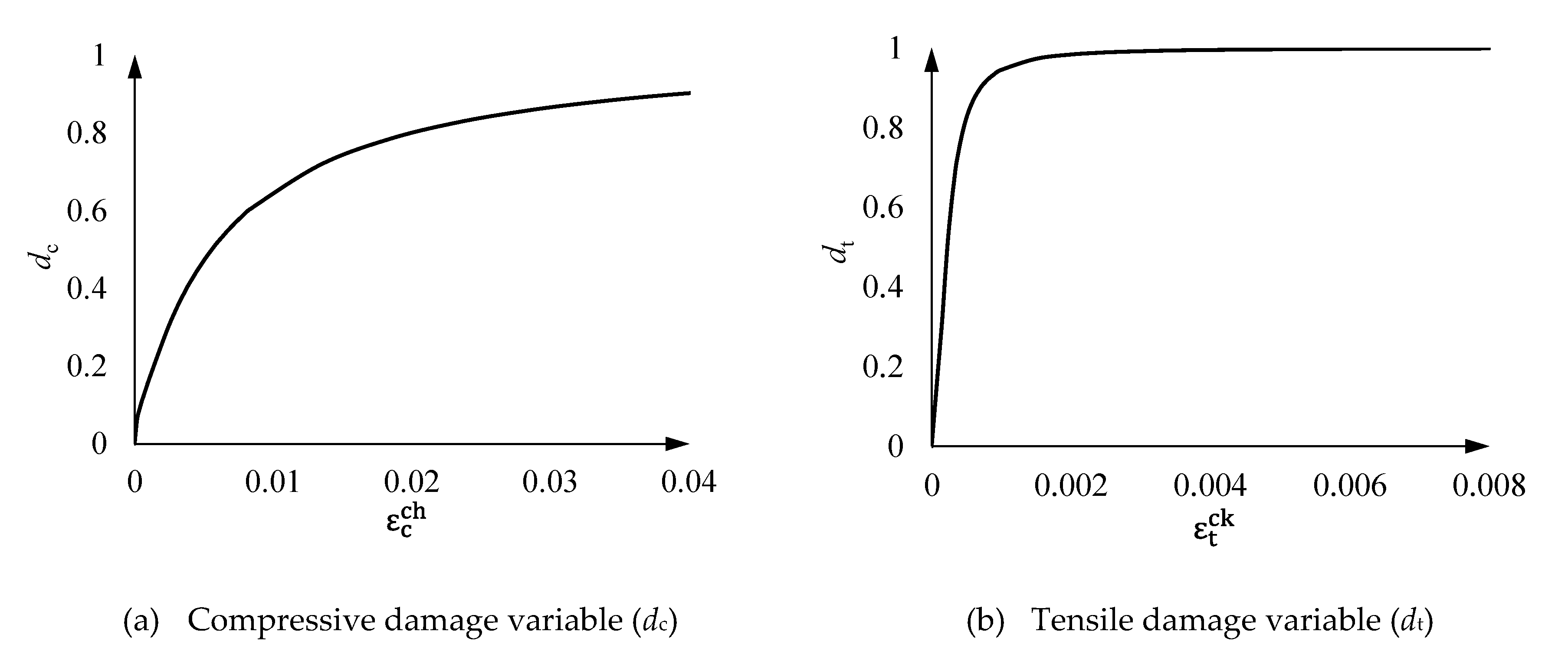
Figure 7.
Uniaxial (compressive and tensile) steel constitutive stress-strain law.
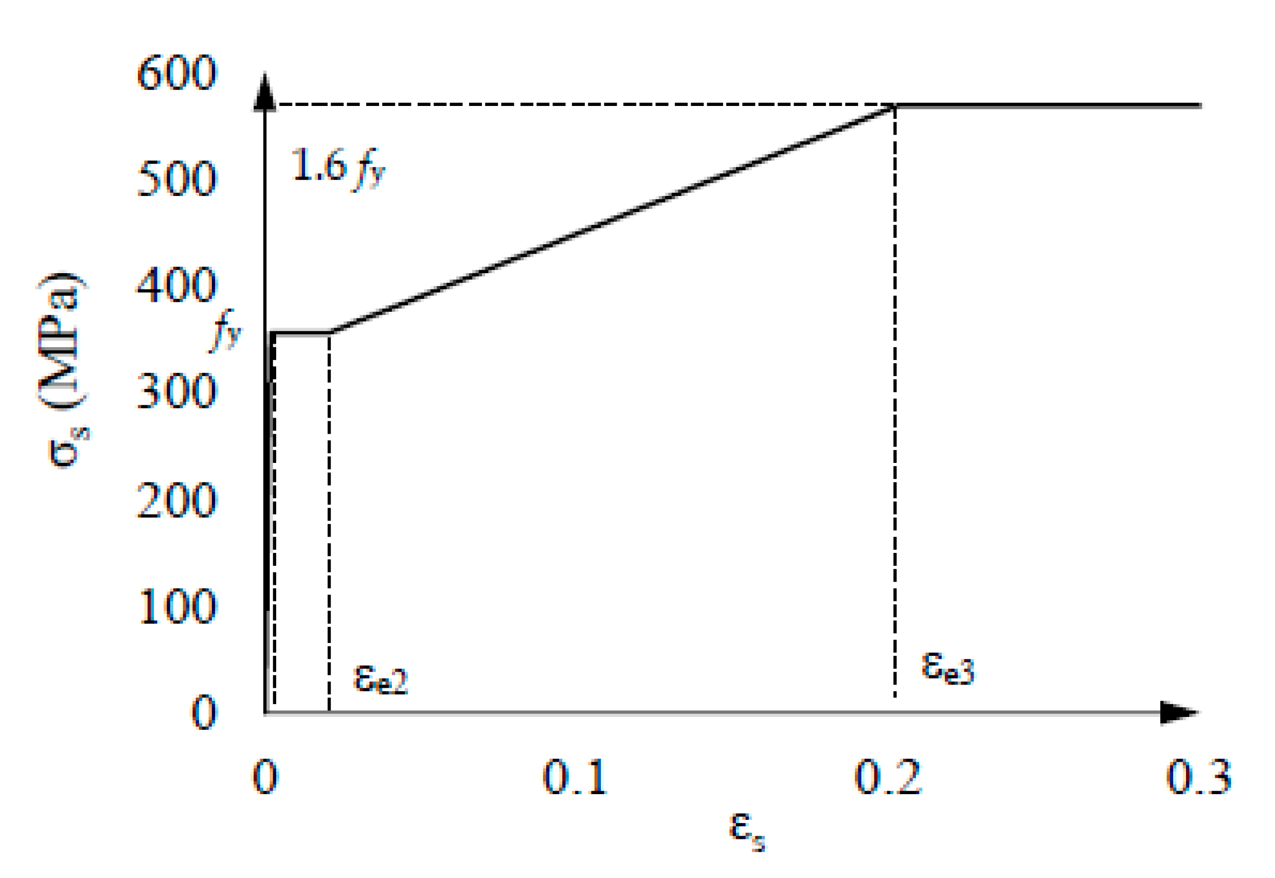
Figure 8.
Loading step 1. Vertical stresses for p0 = 2 MPa.

Figure 9.
Loading step 2. Main results.
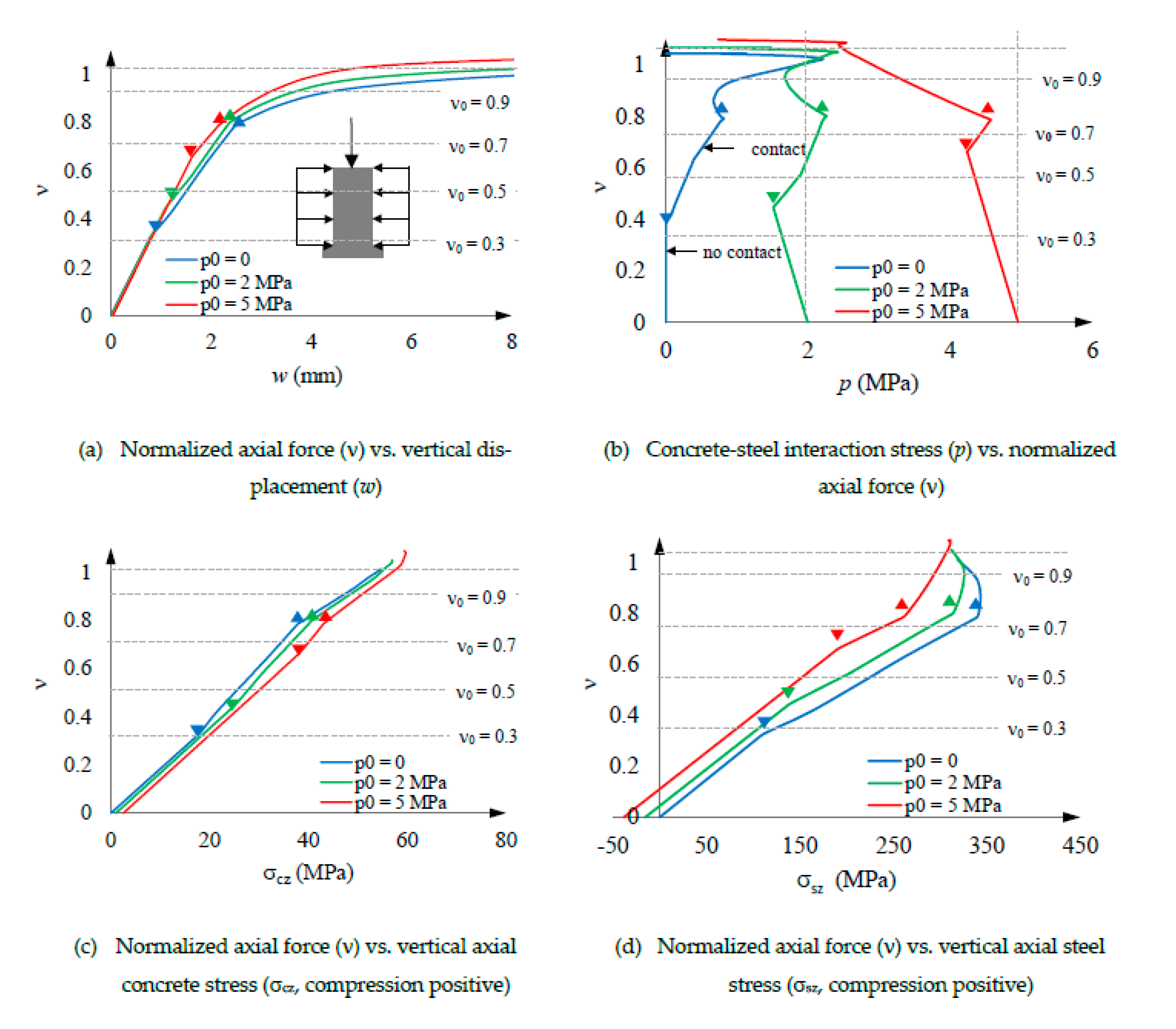
Figure 10.
Loading step 3. V-Δ curves for central columns in Figure 2. Analysis without considering the concrete damage model (subsection 4.3).
Figure 10.
Loading step 3. V-Δ curves for central columns in Figure 2. Analysis without considering the concrete damage model (subsection 4.3).
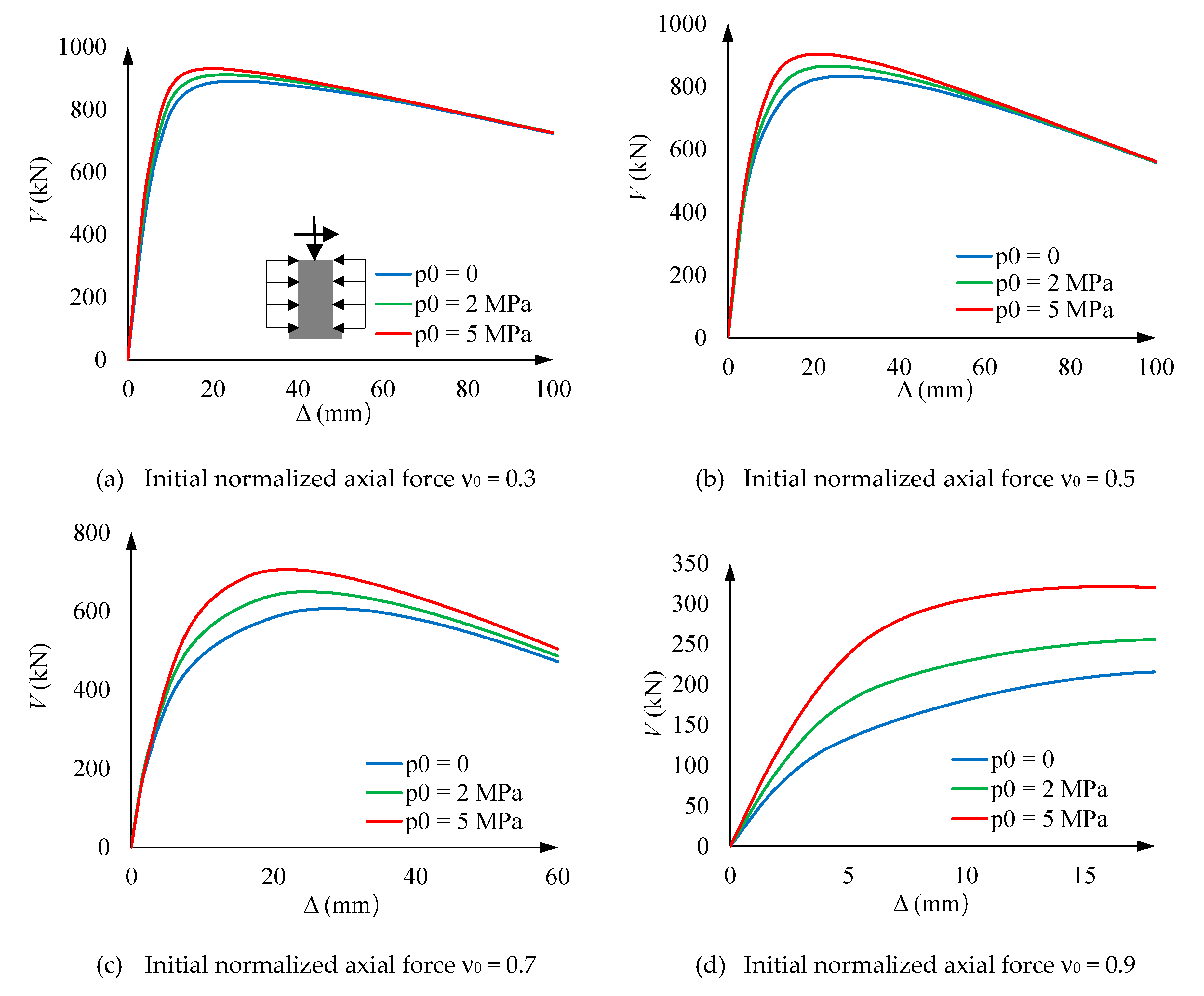
Figure 11.
Loading step 3. V-Δ curves for central columns in Figure 2. Analysis by considering the concrete damage model (subsection 4.3).
Figure 11.
Loading step 3. V-Δ curves for central columns in Figure 2. Analysis by considering the concrete damage model (subsection 4.3).
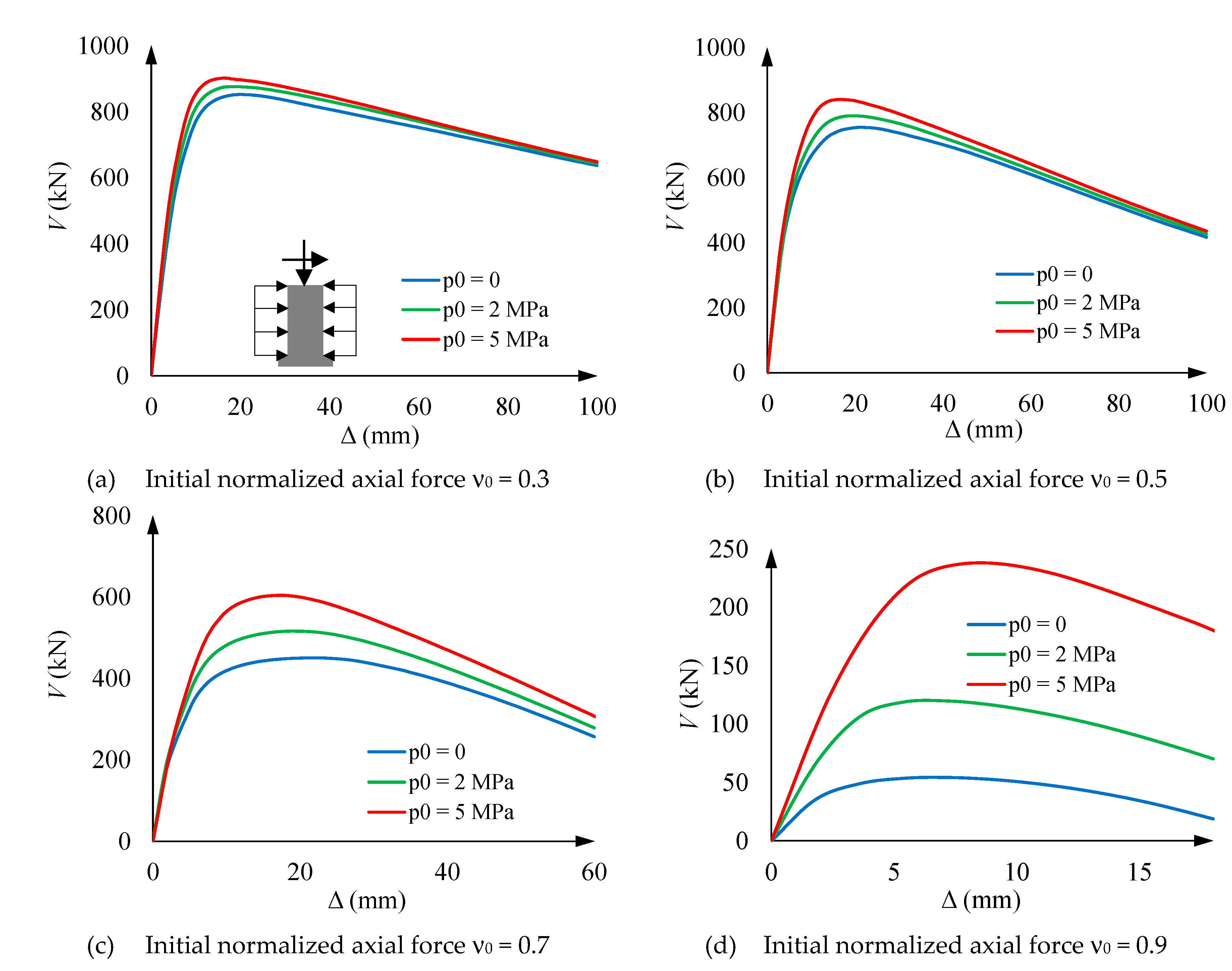
Figure 12.
Loading step 3. Shear force (V) vs. concrete (σcz) and steel (σsz) maximum compressive and tensile vertical stress in the column segment bottom section.
Figure 12.
Loading step 3. Shear force (V) vs. concrete (σcz) and steel (σsz) maximum compressive and tensile vertical stress in the column segment bottom section.
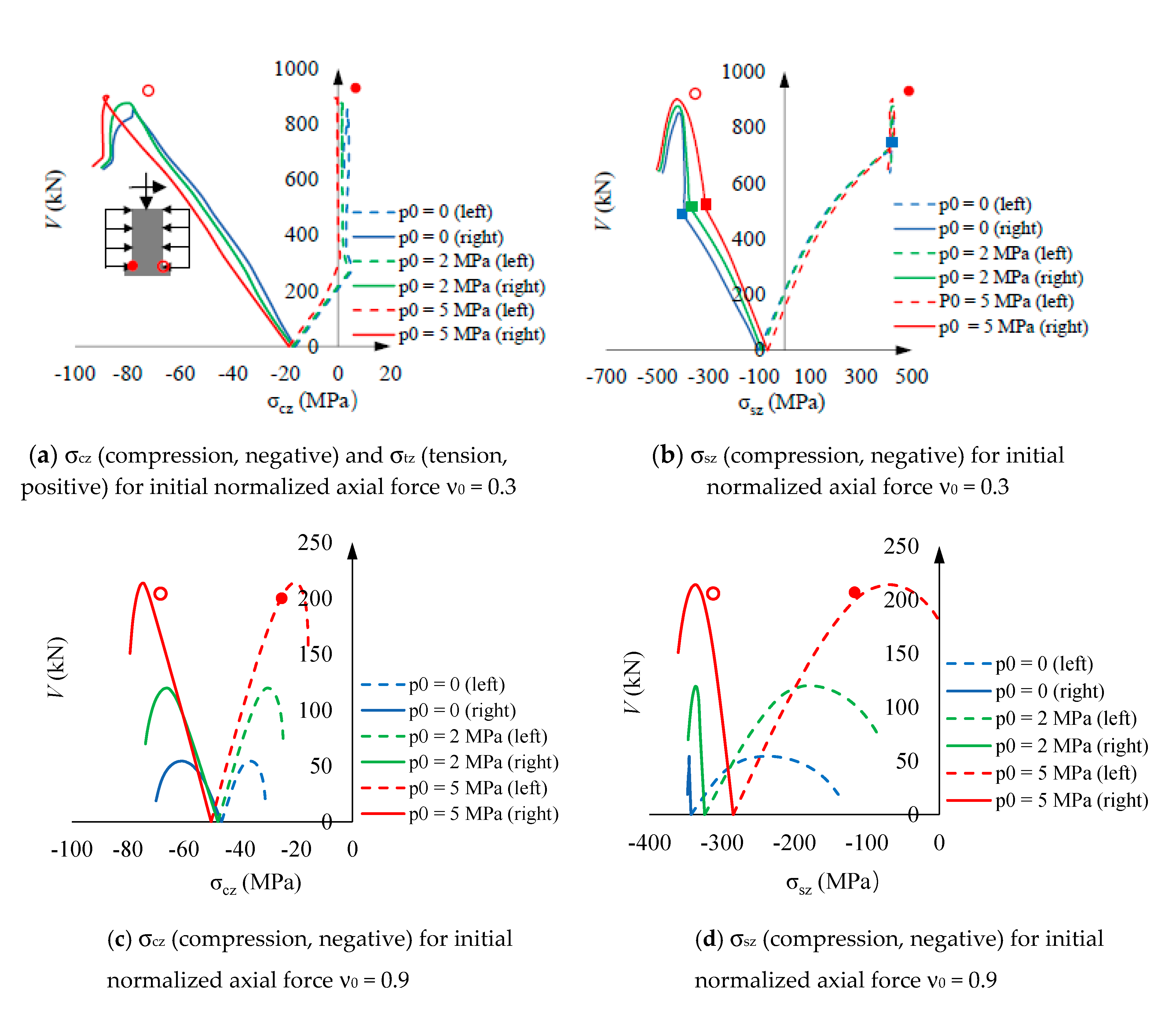
Figure 13.
Loading step 3´+. V-Δ curves for the right columns in Figure 2 (positive sign in equation (8)).
Figure 13.
Loading step 3´+. V-Δ curves for the right columns in Figure 2 (positive sign in equation (8)).
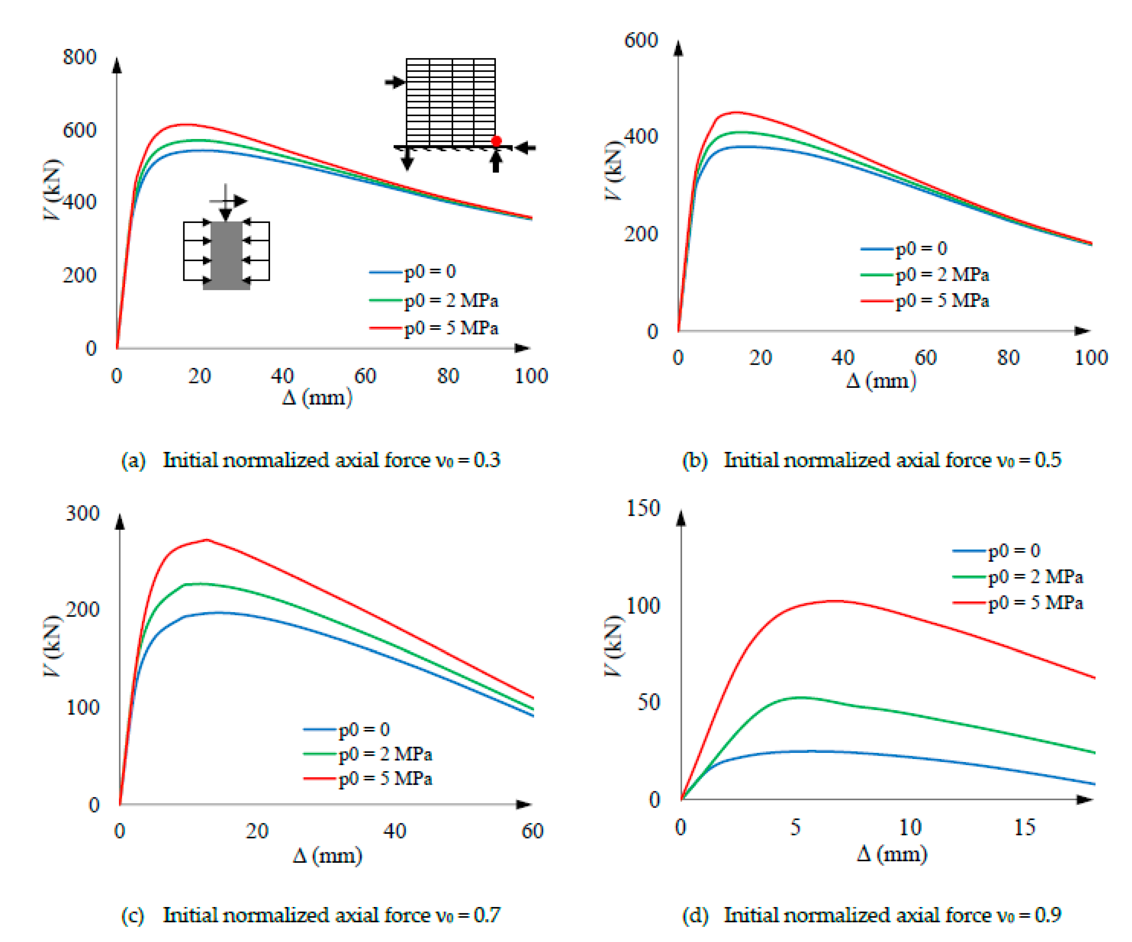
Figure 14.
Loading step 3´−. V-Δ curves for the left columns in Figure 2 (negative sign in equation (8)).
Figure 14.
Loading step 3´−. V-Δ curves for the left columns in Figure 2 (negative sign in equation (8)).
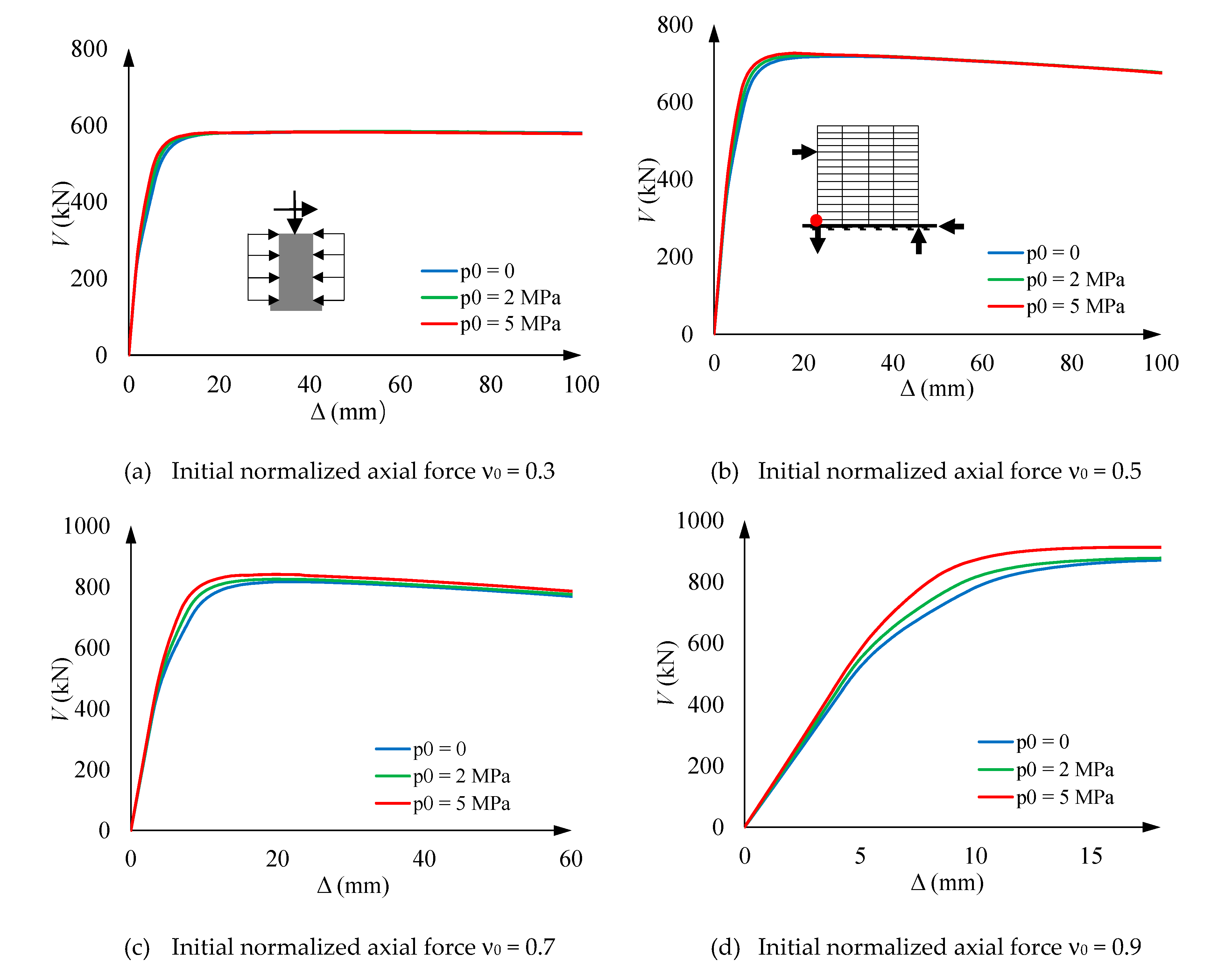
Figure 15.
Sectional interaction diagrams ν-μ (normalized axial force vs. bending moment).
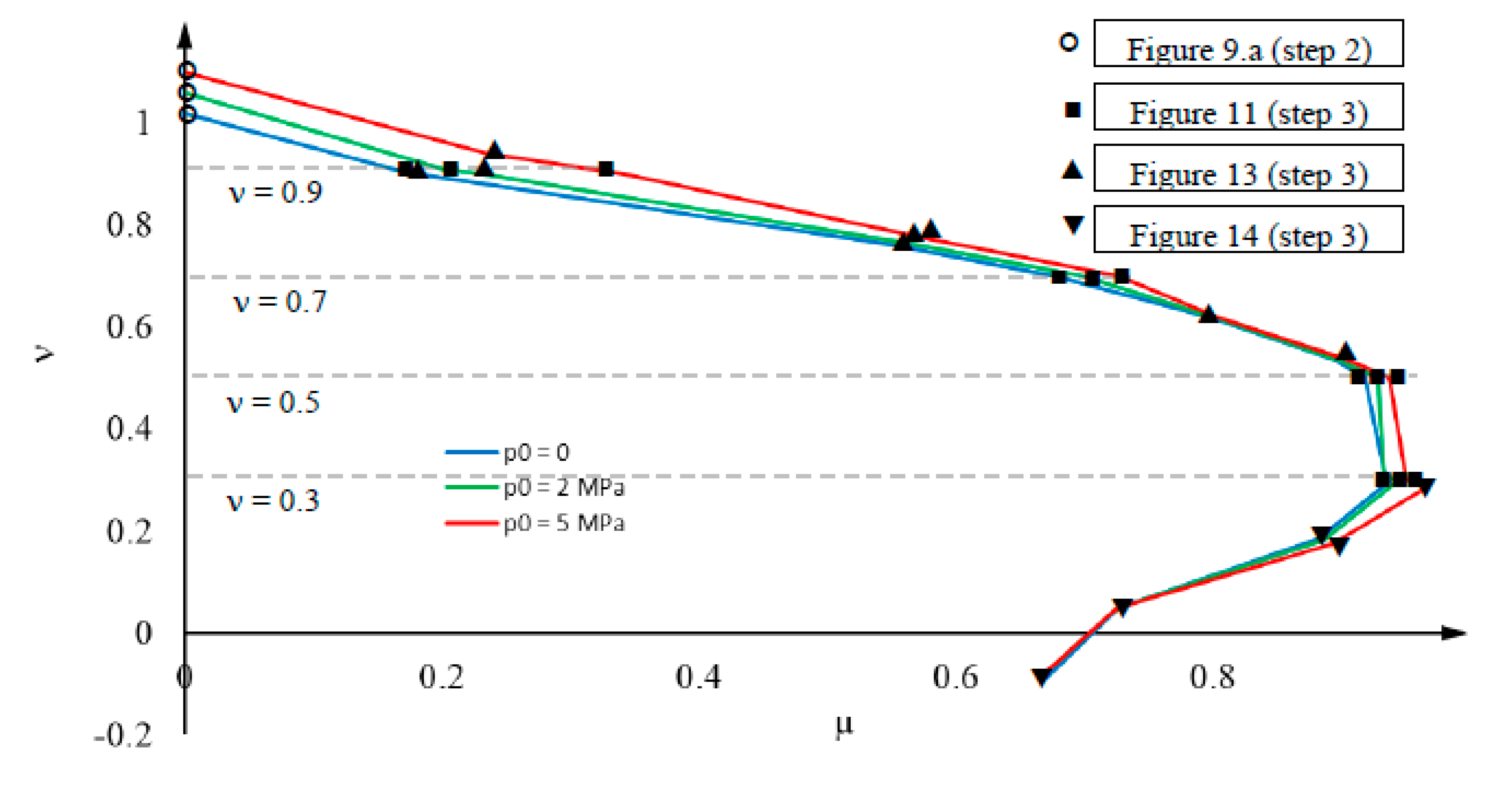
Figure 16.
Global V-Δ (shear force vs. lateral displacement) plots for a building framed story (Figure 2).
Figure 16.
Global V-Δ (shear force vs. lateral displacement) plots for a building framed story (Figure 2).
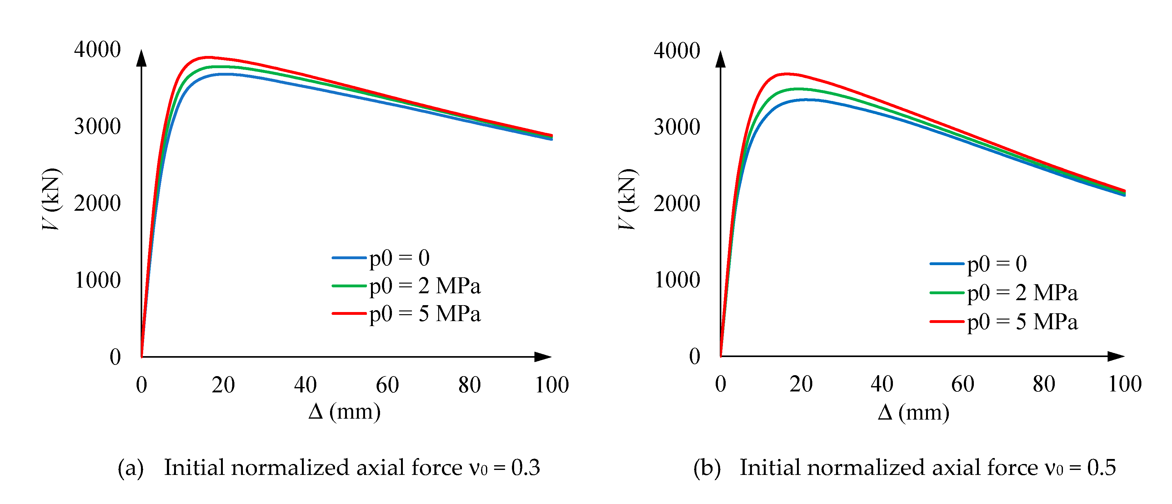

Table 1.
Geometric and mechanical properties of the analyzed column segments (specimens).
| Core diameter D (mm) | Tube thickness t (mm) | Segment length L (m) | Concrete compressive strength fck (MPa) | Steel yield point fy (MPa) | Active hoop prestress p0 (MPa) | Initial normalized axial compression ν0 |
| 500 | 8 | 1.5 | 30 | 355 | 0 / 2 / 5 | 0.3 / 0.5 / 0.7 / 0.9 |
Disclaimer/Publisher’s Note: The statements, opinions and data contained in all publications are solely those of the individual author(s) and contributor(s) and not of MDPI and/or the editor(s). MDPI and/or the editor(s) disclaim responsibility for any injury to people or property resulting from any ideas, methods, instructions or products referred to in the content. |
© 2023 by the authors. Licensee MDPI, Basel, Switzerland. This article is an open access article distributed under the terms and conditions of the Creative Commons Attribution (CC BY) license (http://creativecommons.org/licenses/by/4.0/).
Copyright: This open access article is published under a Creative Commons CC BY 4.0 license, which permit the free download, distribution, and reuse, provided that the author and preprint are cited in any reuse.


