
Submitted:
11 August 2023
Posted:
11 August 2023
You are already at the latest version
Abstract
This paper proposes a compact wideband split ring resonator (SRR) based C-shaped antenna for 5G new radio (NR) band n258 millimeter wave (mm-Wave). The proposed antenna covers a wideband frequency range from 24.1 GHz to 28.3 GHz with a reflection coefficient below -10 dB. Stubs are used at each C-shaped element for impedance matching of the antenna. The proposed antenna comprises SRRs with stubs to increase the bandwidth and gain simultaneously for better performance in mm-Wave applications. A simple SRR structure is modeled to function as a reactive impedance surface with inductive property for frequencies less than 30.2 GHz. The proposed antenna realizes an impedance bandwidth of 16.1% and covers a wideband of 4.2 GHz (24.1 GHz -28.3 GHz). The use of stubs and SRR has improved the performance of the proposed antenna at mm-Wave frequencies. Specifically, the deployment of the SRR is able to produce an improved gain for the overall direction of the antenna. The simulation and measured results agree well and maintain a 7.49 dBi gain with a bandwidth of 4.2 GHz. An average efficiency of 90% can be attained in the operating range of the antenna. The designed antenna is applicable for 5G NR Band n258.
Keywords:
SRR
; millimeter wave
; 5G
; Wide-band Antenna
1. Introduction
The viability of 5G networks extends the facility of spectrum utilization, network flexibility, and multi-connectivity in the sphere of wireless technology. The development of 5G increases the high data rate and improves the occupancy of bandwidth in many communication devices, allowing higher mobile users per unit area [1]. In 5G millimeter wave technology, various approaches have been taken to enhance bandwidth, improve antenna gain, and achieve miniaturization. These approaches could help invent future innovations that meet millimeter wireless standards and play a key role in the communication medium.
To realize a wide bandwidth in millimeter wave frequencies, a defected ground approach [2] was used in antenna design. A new wideband array antenna was considered for mm-Wave applications intended for high data rates in wireless communications [3]. In other related work, inverted L-slots were placed at radiating elements to improve the bandwidth of an individual feed and match the impedance parameter of the antenna for millimeter wave applications in 5G mobile applications [4]. An electromagnetic band gap (EBG) ground was positioned side by side in the antenna array for better matching and improved radiating properties of the antenna, making it acceptable for enabling mobile terminals in 5G communication [5]. Slots can be added to improve the bandwidth in mm-Wave frequencies and reduce the effective area in the radiating patch [6]. An EBG-based substrate-integrated waveguide (SIW) antenna has been shown and proven to operate in mm-Wave applications [7].
Apart from bandwidth enhancement, gain improvement is also considered one of the key achievements in 5G antenna designs. The split ring resonator (SRR) has been introduced in antenna design to improve gain in 5G wireless technology that operates at the low band (600-850 MHz), mid-band (3.4-3.6 GHz), and higher band in millimeter wave (mm-Wave) frequencies of (24-28) GHz, as reported in [8,9]. Array antennas have also been used for mm-Wave 5G smartphones to improve gain in the antenna design, as reported in [10]. In addition, dielectric resonator antennas (DRA) have been used to improve gain and bandwidth for mm-Wave applications, as reported in [11,12]. In the view of wireless communication under 5G technology, a dual E-shaped patch antenna generated a multiband with stubs inserted between the elements and enhanced the wideband property into ultra-wideband, which has shown better results in terms of gain, as reported in [13,14]. Furthermore, meta-surface based approach has also been used in 5G antennas to improve gain, as reported in [15].
In addition to bandwidth and gain enhancement, the design of 5G antennas is also considered in terms of miniaturization. A basic square-shaped patch loaded with a slot was proposed in [16] to achieve miniaturization. An optimized low-profile antenna is designed using an artificial magnetic conductor reflector, maintaining low cross-polarization and increasing gain and bandwidth with antenna efficiency [17]. A miniaturized mm-Wave antenna has also been designed for a multiple-input multiple-output 5G antenna that operates with beam scanning ability [18]. Nevertheless, all reported works still lack in achieving a compact antenna that operates at mm-Wave 5G new radio (NR) band and attains high gain for an omnidirectional radiation pattern.
In this work, a C-shaped patch antenna was modeled with simple split ring resonators (SRR) to improve the quasi-omnidirectional radiation pattern over a wideband for 5G mm-Wave applications. Rectangular stubs were used preceding every portion of the C-shaped patch to eliminate the dual band and enable the wideband property of the antenna. In general, monopole microstrip patch antennas face limitations such as narrow bandwidth [19] and low gain [20]. To overcome these limitations, careful analyses were carried out, and the proposed design was optimized and investigated at each phase to finally develop the antenna with wide-band, omnidirectional pattern, and high gain characteristics. A compact wideband antenna was proposed in frequency range 2 (FR2) 5G NR band n258. The impedance bandwidth of 16.1% is achieved, covering two bands centered at 25.2 GHz and 27.7 GHz frequencies.
2. Antenna Design and Analysis
The geometry of the compact wideband SRR-based antenna for 5G mm-Wave application is presented in Figure 1. The designed wideband antenna was printed on a Rogers RT/duroid 5880 substrate with a relative permittivity of 2.2, and a dielectric loss tangent of 0.0009. The overall dimension of the antenna is covered by the length Ls, width Ws, and substrate height of 1.6 mm. SL and SW are the length and width of the stub. Table 1 shows the complete dimensions of the proposed antenna. The dimensions of the ground plane Gp are placed at the lowermost sheet of the antenna to enable omni-directional radiation pattern characteristics. At each element in the array, the rectangular stubs are used prior to the C-shaped structure to reduce the losses and widen the bandwidth of the antenna as shown in the parametric analysis. Then, an SRR is used to improve the radiation pattern characteristic of the antenna. Finally, 4 elements of C-shaped radiating element SRR could be developed as shown in Figure 1.

Table 1.
Parametric Dimension table for the proposed antenna.
| Dimension | Value | Dimension | Value | Dimension | Value |
|---|---|---|---|---|---|
| LS | 43 | D | 2 | C7 | 2 |
| WS | 45 | SL | 4 | S1 | 7 |
| GP | 9 | SW | 4 | S2 | 7 |
| H | 1.6 | WP | 8 | S3 | 6.5 |
| LP1 | 4 | P1 | 2 | SP | 1 |
| LP2 | 16 | C4 | 1 | N | 1 |
| LP3 | 15 | C5 | 14 | ||
| C3 | 1.8 | C6 | 10 |
1All Dimensions are in mm.
2.1. SRR unit cell design
Figure 2 (a) shows the SRR unit cell design along with its reflection phase result. A simple 7 mm x 7 mm square-shaped SRR unit cell was adopted with a ring width of 1 mm. The slit width between the ring is C4. The boundaries of the SRR unit cell were covered by a perfect electric conductor (PEC) and perfect magnetic conductor (PMC) perpendicular to the incident electric (E) and magnetic (H) fields. This SRR was subjected to transverse electromagnetic waves (TEM) coming from the +z direction. As shown in Figure 2(b), the SRR acts as an inductor below the center frequency at 30.2 GHz which can help to store the magnetic energy that could compensate for the electrical energy [21]. This reflection phase characteristic of the SRR is expected to enhance the radiation characteristics of the antenna within the operating range from 24.2 to 28.3 GHz.
2.2. Equivalent circuit model of the SRR-based C-Shaped antenna
The equivalent circuit for the compact wideband SRR-based antenna is shown in Figure 3. Here the circuit is established based on resistor (R), inductor (L), and capacitor (C), and the equivalent circuit is considered only for one element in the array from the feed line. Zc is the characteristic impedance and Rf is the loss present in the feed line. The equivalent circuit model is adopted based on [22] and modified according to the dimension of the proposed antenna in this work. The inductor L1 and Capacitor C1 are represented [22] as microstrip lines in the equivalent circuit.
The mathematical expression for L1 and C1 are represented as follows.
where D and H represent the width of the feedline and height of the substrate respectively and is the relative permittivity. In the equivalent circuit model, S represents a stub placed for impedance matching and for widening the bandwidth. The width (Wstub) and length (Lstub) of the stub [13] are expressed in equations (3) and (4) respectively.
where c is the speed of the light and fr is the resonant frequency. Based on the C5 and C6 dimensions as shown in Figure 1, the effective length (Leff1) and width (Weff1) of the C-Shaped radiating strip for one element can be calculated as follows,
The expression for the capacitor (C2), resistor (R2), and inductor (L2) of the equivalent circuit can be expressed in equations 7, 8, and 9.
where the quality factor, Q can be expressed as,
In the equivalent circuit model, L4 is the inductance and C4 is the capacitance for the square split ring resonator. For a square split ring resonator, the resonant frequency fsrr is expressed as
where C4 is the total equivalent capacitance of the SRR,
where is the characteristic impedance and is the total equivalent inductance of the SRR. The L4 can be expressed as follows,
where γ = 2.853 for a wire loop of the square geometry and the Leff1 can be calculated based on the total length of the SRR as,
3. Results and Discussion
The simulation was carried out using the HFSS EM modeling tool. The proposed antenna was fabricated and tested using the Vector Network Analyzer of R & S ZND 40. The S-parameter and peak gain results were observed in each simulation stage to observe the effect of the sub-matching and the SRR.
3.1. The Design Evolution of The Proposed Antenna
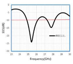
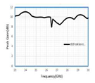
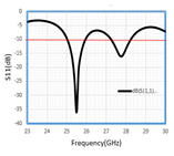
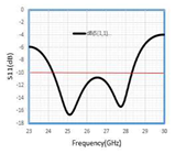
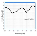
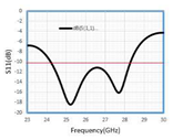
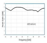
The evolution process of the proposed antenna is shown in Table 2. The reflection coefficient response for each stage is shown in Figure 4. of the proposed SRR-based antenna. Antenna 1 with diameter D2mm resonates with two resonant frequencies at 25.4 and 27.8 with S11 of -24.07 and -14.71 and covers a bandwidth in each band at 1.2 and 0.9 with a gain of 9.22. The addition of two stubs in antenna 2 increases the bandwidth of the antenna and resonates at two frequencies with an increase in S11 of -36.05 at 25.5 and -16.06 at 27.8 with a bandwidth of 1 GHz and 1.1 GHz. In antenna 3, the stubs were placed before each element of the antenna and it covers the wider bandwidth of 4.1 GHz and resonates at two frequencies of 25.1 and 27.8 GHz with a reflection coefficient of -16.6 and -15.29, and attains a peak gain of 7.1 dB. The proposed Array Antenna resonates at 25.2 and 27.7 with S11 of -18.43 and -16.11 with an increased peak gain of 7.49 dB as shown in Figure 5(b). The results from the design evaluation are summarized in Table 3.
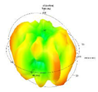
The use of SRR to improve the overall gain of the antenna may not be clearly observed through this 2D radiation pattern result, because it does not show the radiation pattern characteristic for the overall beam coverage. Therefore, in what follows, the 3D radiation pattern of the antenna is investigated.
3.2. D Radiation Pattern Analysis
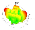
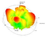
In this design, the SRR mainly helps to improve the antenna gain for most of the directions, and thus attains an omnidirectional radiation pattern. From Table 2. It can be seen that the antenna’s reflection coefficient remains the same for Antenna 3 and the proposed antenna. This explains that the wide-band property was obtained mainly from the use of stubs. The 2D radiation patterns shown in Table 2 are also almost similar for both Antenna 3 and the proposed antenna, just that a slight improvement can be obtained in terms of the peak gain. To further observe the advantage of the SRR, the 3D radiation pattern results are compared. Figure 6 and Figure 7 show the radiation pattern results for
Antenna 3 and the proposed antenna, respectively. The results also compared two operating frequencies, 25.1 GHz and 27.8 GHz. Compared with Antenna 3, the proposed antenna manages to radiate with more gain for a wide range of angles. Hence, it shows that the high gain is not limited to certain directions/angles but covers most of the directions with the use of the SRR. The results were also further validated with the observation of the total efficiency and the peak gain proposed antenna and the antenna without SRR. It can be seen from Figure 8 that the antenna efficiency reaches 99% with better gain in the operating range of the antenna.
3.3. The Fabricated Antenna and The Measurement Results
The measurement and simulation results of S11 against frequency are shown in Figure 9 (a). The top view and rear view of the fabricated Antenna are shown in Figure 9 (b). The measurement was made in the laboratory using a Vector network analyzer (R & S ZND 40). After measuring the proposed wideband antenna resonates at 25.2GHz and 27. 7 GHz in the mm-Wave band (24.1 GHz - 28.3 GHz) below -10 dB. Table 4 shows the comparison of simulated and measured results relevant to the impedance bandwidth. The impedance bandwidth of simulated results is 16.1(%) and 13.40(%) is for measured results. This slight mismatch could be due to the soldering effect of the SMA port on the transmission line.
Figure 10 shows the polar radiation pattern cut xz plane for 25.2 and 27.7 GHz frequencies. It shows that a high gain can be obtained for most directions with acceptable cross-polarization.
Table 5 presents the comparison of the proposed antenna with similarly proposed works for mm-Wave operating frequencies. In terms of dimension, the proposed antenna has a comparable size to most of the works. Only works [23] and [24] have smaller sizes compared with the proposed antenna. In terms of bandwidth and gain the proposed antenna have better results compared with most of the existing works reported in the literature. Specifically, the use of SRR cannot be compared with the existing works as the 3D radiation patterns are not revealed. Therefore, the advantage of the SRR was comprehensively analyzed and discussed.
4. Conclusion
This paper proposed a C-shaped SRR-based 5G mm-Wave antenna, which is a significant contribution to the field of wireless communication. The antenna's stub matching technique improves its bandwidth, while the SRR enhances its radiation characteristics. This study modeled a simple SRR to have inductive properties for frequencies below 30.2 GHz, which enables the antenna to have better radiation characteristics at its operating range. The proposed antenna operates with a wide band that resonates at 25.2 GHz and 27.7 GHz frequencies, with an impressive impedance bandwidth of 4.02 (24.1-28.3 GHz) and a reflection coefficient of -18.431 dB and -16.113 dB, respectively. The proposed compact wideband array antenna has an acceptable peak gain of 7.49 dBi with the use of SRR. These results outperform most of the existing works reported in the literature in terms of bandwidth and gain. Furthermore, the proposed antenna is applicable for use in 5G NR Band n258 FR2 (mm-Wave) at the 5G spectrum. The comprehensive analyses and discussions of the SRR's advantages in this paper demonstrate its potential to improve the antenna's radiation properties and bandwidth. Overall, the proposed C-shaped SRR-based 5G mm-Wave antenna is a promising candidate for future wireless communication systems and can contribute to the development of 5G technology.
Author Contributions
Conceptualization, Suresh Angadi and Thennarasan Sabapathy; Data curation, Mohamed Himdi; Formal analysis, N.S. Raghava; Funding acquisition, Hamsakutty Vettikalladi and Ali M. Almuhlafi; Investigation, Suresh Angadi, Muzammil Jusoh and Hamsakutty Vettikalladi; Methodology, Suresh Angadi and N.S. Raghava; Project administration, Hamsakutty Vettikalladi; Resources, N.S. Raghava; Software, Ali M. Almuhlafi; Validation, Thennarasan Sabapathy and Ali M. Almuhlafi; Visualization, Muzammil Jusoh; Writing – original draft, Suresh Angadi and Thennarasan Sabapathy; Writing – review & editing, Thennarasan Sabapathy and Mohamed Himdi. All authors have read and agreed to the published version of the manuscript.
Funding
Researchers Supporting Project number (RSP2023R482), King Saud University, Riyadh, Saudi Arabia.
Data Availability Statement
Not applicable.
Acknowledgments
Not applicable.
Conflicts of Interest
The authors declare no conflict of interest.
Patents
Not applicable.
References
- J. R. James and P. S. Hall, Eds., Handbook of Microstrip Antennas, Volume 1. Institution of Engineering and Technology, 1989. [CrossRef]
- M. Khalid et al., “4-Port MIMO Antenna with Defected Ground Structure for 5G Millimeter Wave Applications,” Electronics, vol. 9, no. 1, p. 71, Jan. 2020. [CrossRef]
- H. Alwareth, I. M. Ibrahim, Z. Zakaria, A. J. A. Al-Gburi, S. Ahmed, and Z. A. Nasser, “A Wideband High-Gain Microstrip Array Antenna Integrated with Frequency-Selective Surface for Sub-6 GHz 5G Applications,” Micromachines, vol. 13, no. 8, p. 1215, Jul. 2022. [CrossRef]
- M. Sanad, “Comments on ‘Wide-band E-shaped patch antennas for wireless communications,’” IEEE Trans. Antennas Propagat., vol. 51, no. 9, p. 2541, Sep. 2003. [CrossRef]
- E. M. Wissem, I. Sfar, L. Osman, and J.-M. Ribero, “A Textile EBG-Based Antenna for Future 5G-IoT Millimeter-Wave Applications,” Electronics, vol. 10, no. 2, p. 154, Jan. 2021. [CrossRef]
- P. Merlin Teresa and G. Umamaheswari, “Compact Slotted Microstrip Antenna for 5G Applications Operating at 28 GHz,” IETE Journal of Research, vol. 68, no. 5, pp. 3778–3785, Sep. 2022. [CrossRef]
- A. Verma and S. N. Raghava, “Circularly polarized hybrid mode substrate integrated waveguide antenna for two quadrant scanning beamforming applications for 5G,” Int J RF Microw Comput Aided Eng, vol. 31, no. 10, Oct. 2021. [CrossRef]
- Wen Tao Li, Yong Qiang Hei, Wei Feng, and Xiao Wei Shi, “Planar Antenna for 3G/Bluetooth/WiMAX and UWB Applications With Dual Band-Notched Characteristics,” Antennas Wirel. Propag. Lett., vol. 11, pp. 61–64, 2012. [CrossRef]
- T. S. Rappaport et al., “Millimeter Wave Mobile Communications for 5G Cellular: It Will Work!,” IEEE Access, vol. 1, pp. 335–349, 2013. [CrossRef]
- W. Hong, K.-H. Baek, and S. Ko, “Millimeter-Wave 5G Antennas for Smartphones: Overview and Experimental Demonstration,” IEEE Trans. Antennas Propagat., vol. 65, no. 12, pp. 6250–6261, Dec. 2017. [CrossRef]
- N. S. Murthy, “Improved Isolation Metamaterial Inspired Mm-Wave MIMO Dielectric Resonator Antenna For 5g Application,” PIER C, vol. 100, pp. 247–261, 2020. [CrossRef]
- M. D. Alanazi, “A Review of Dielectric Resonator Antenna at Mm-Wave Band,” Eng, vol. 4, no. 1, pp. 843–856, Mar. 2023. [CrossRef]
- K. K. Naik, “Improvement of wider bandwidth using dual e–shaped antenna for wireless communications in 5G applications,” Analog Integr Circ Sig Process, vol. 109, no. 1, pp. 93–101, Oct. 2021. [CrossRef]
- “Wideband Slotted Planar Inverted-F Antenna using Eccosorb MCS Absorber for Millimeter-Wave Applications,” IJPAP, Jun. 2021. [CrossRef]
- S. Tariq, S. I. Naqvi, N. Hussain, and Y. Amin, “A Metasurface-Based MIMO Antenna for 5G Millimeter-Wave Applications,” IEEE Access, vol. 9, pp. 51805–51817, 2021. [CrossRef]
- M. Ikram, M. S. Sharawi, and A. Shamim, “A millimeter-wave connected antenna array for 5G applications,” in 2017 IEEE International Symposium on Antennas and Propagation & USNC/URSI National Radio Science Meeting, San Diego, CA, USA: IEEE, Jul. 2017, pp. 1449–1450. [CrossRef]
- Z. Jiang, Z. Wang, L. Nie, X. Zhao, and S. Huang, “A Low-Profile Ultrawideband Slotted Dipole Antenna Based on Artificial Magnetic Conductor,” Antennas Wirel. Propag. Lett., vol. 21, no. 4, pp. 671–675, Apr. 2022. [CrossRef]
- M. M. Hossain, M. J. Alam, and S. I. Latif, “Orthogonal Printed Microstrip Antenna Arrays for 5G Millimeter-Wave Applications,” Micromachines, vol. 13, no. 1, p. 53, Dec. 2021. [CrossRef]
- P. Kumar et al., “An Ultra-Compact 28 GHz Arc-Shaped Millimeter-Wave Antenna for 5G Application,” Micromachines, vol. 14, no. 1, p. 5, Dec. 2022. [CrossRef]
- M. N. Hasan, S. Bashir, and S. Chu, “Dual band omnidirectional millimeter wave antenna for 5G communications,” Journal of Electromagnetic Waves and Applications, vol. 33, no. 12, pp. 1581–1590, Aug. 2019. [CrossRef]
- N. S. Shamsuri Agus et al., “Combined RIS and EBG Surfaces Inspired Meta-Wearable Textile MIMO Antenna Using Viscose-Wool Felt,” Polymers, vol. 14, no. 10, p. 1989, May 2022. [CrossRef]
- A. Balanis, Antenna theory: analysis and design, 3rd ed. Hoboken, NJ: John Wiley, 2005.
- X. Shen, Y. Liu, L. Zhao, G.-L. Huang, X. Shi, and Q. Huang, “A Miniaturized Microstrip Antenna Array at 5G Millimeter-Wave Band,” Antennas Wirel. Propag. Lett., vol. 18, no. 8, pp. 1671–1675, Aug. 2019. [CrossRef]
- K. Bangash, M. M. Ali, H. Maab, and H. Ahmed, “Design of a Millimeter Wave Microstrip Patch Antenna and Its Array for 5G Applications,” in 2019 International Conference on Electrical, Communication, and Computer Engineering (ICECCE), Swat, Pakistan: IEEE, Jul. 2019, pp. 1–6. [CrossRef]
Figure 1.
The Geometry of SRR-based C shaped antenna.
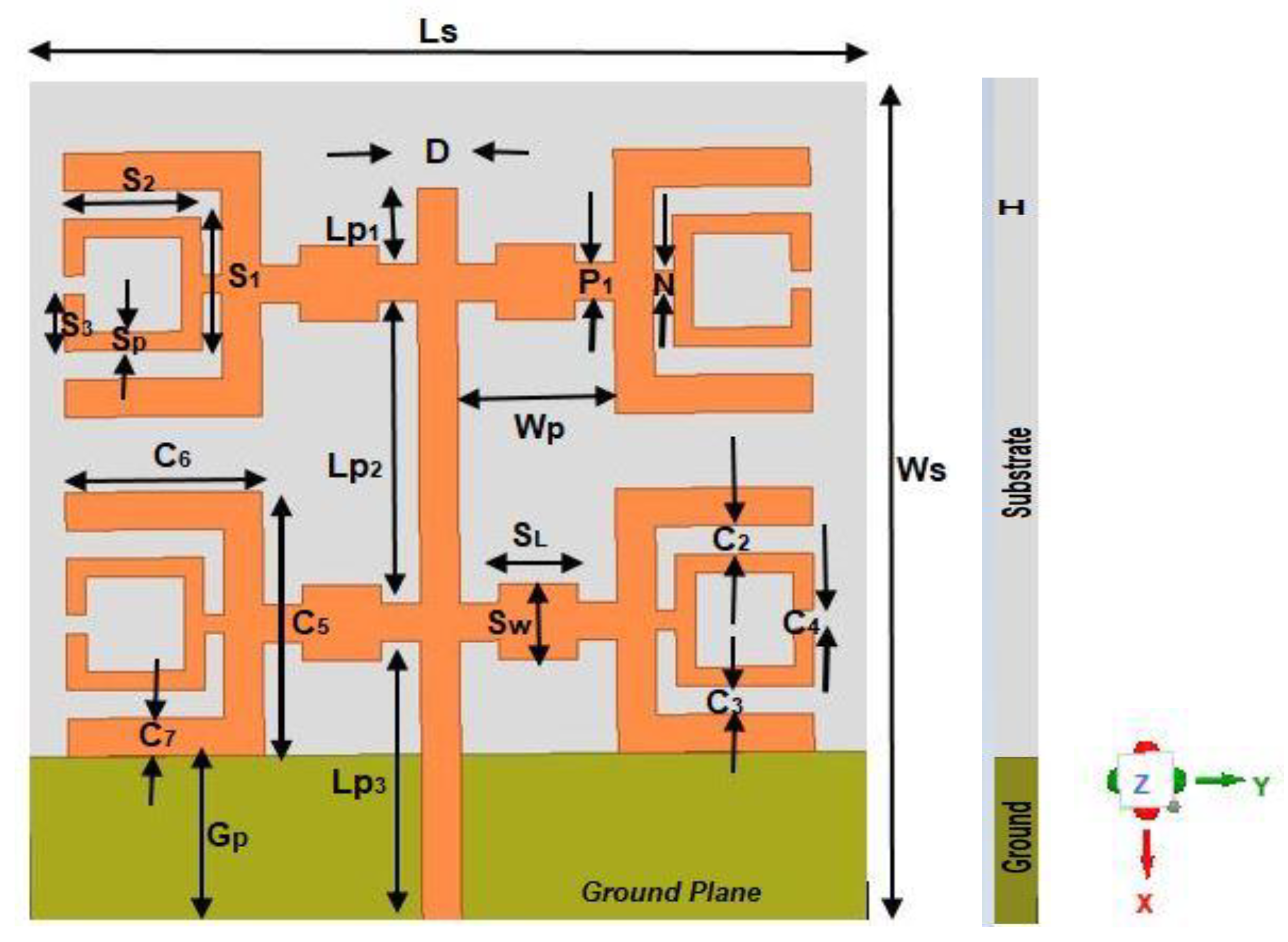
Figure 2.
The SRR design: (a) unit cell (b) Reflection phase result.
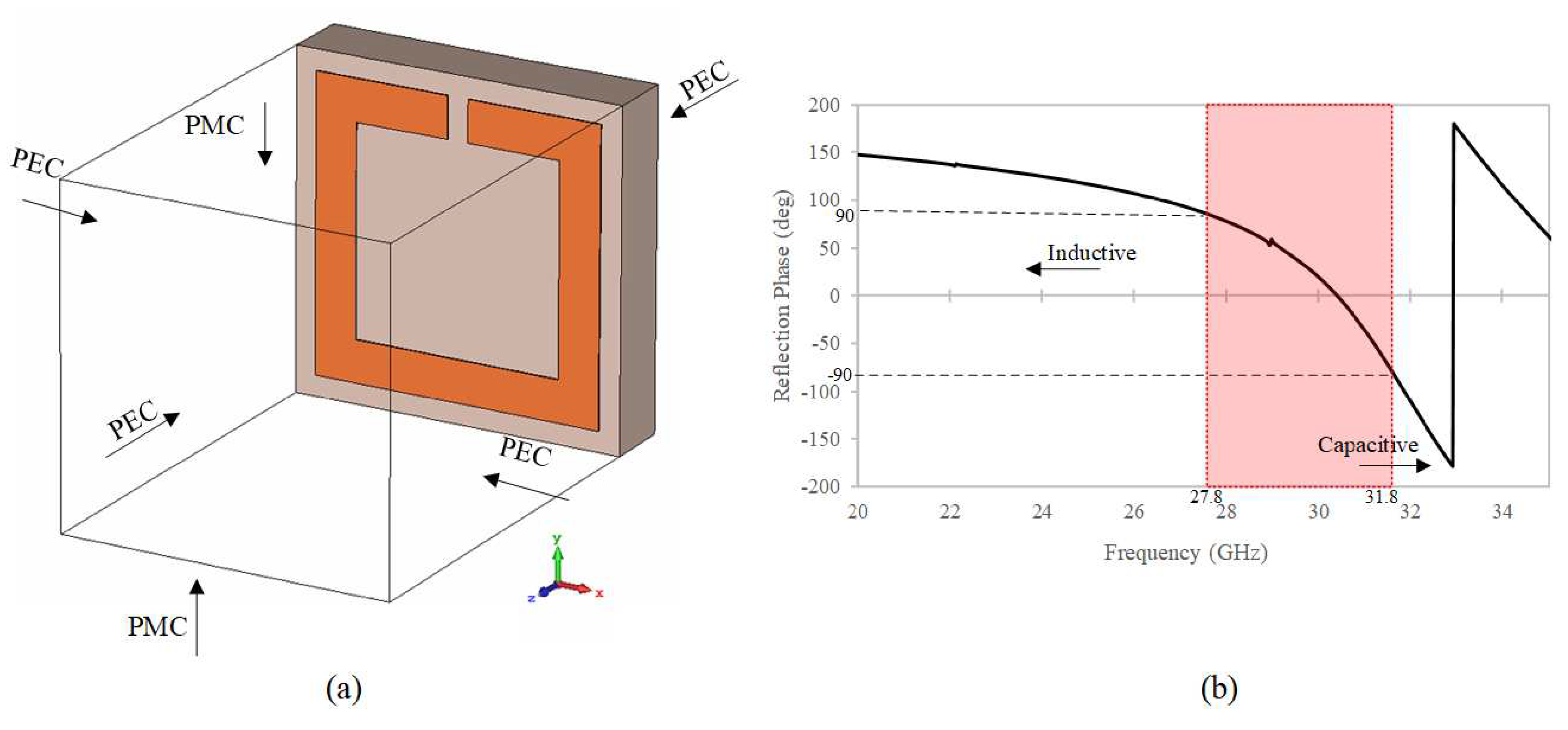
Figure 3.
Equivalent Circuit Model for a single element in the proposed antenna.
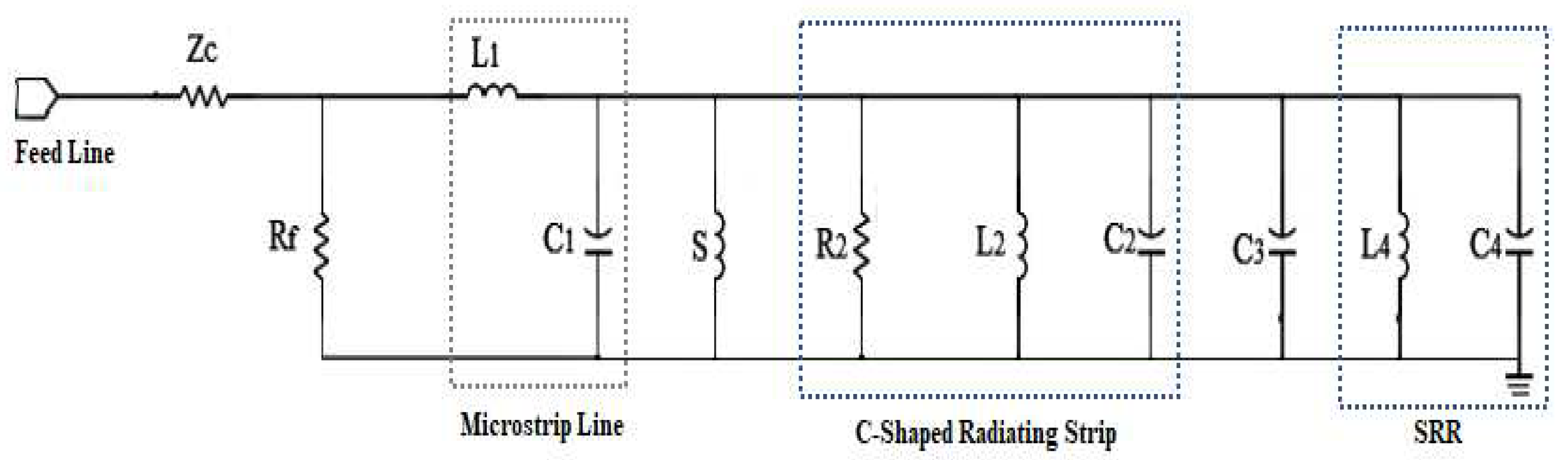
Figure 4.
Parametric Analysis SRR-based C-Shaped Antenna.
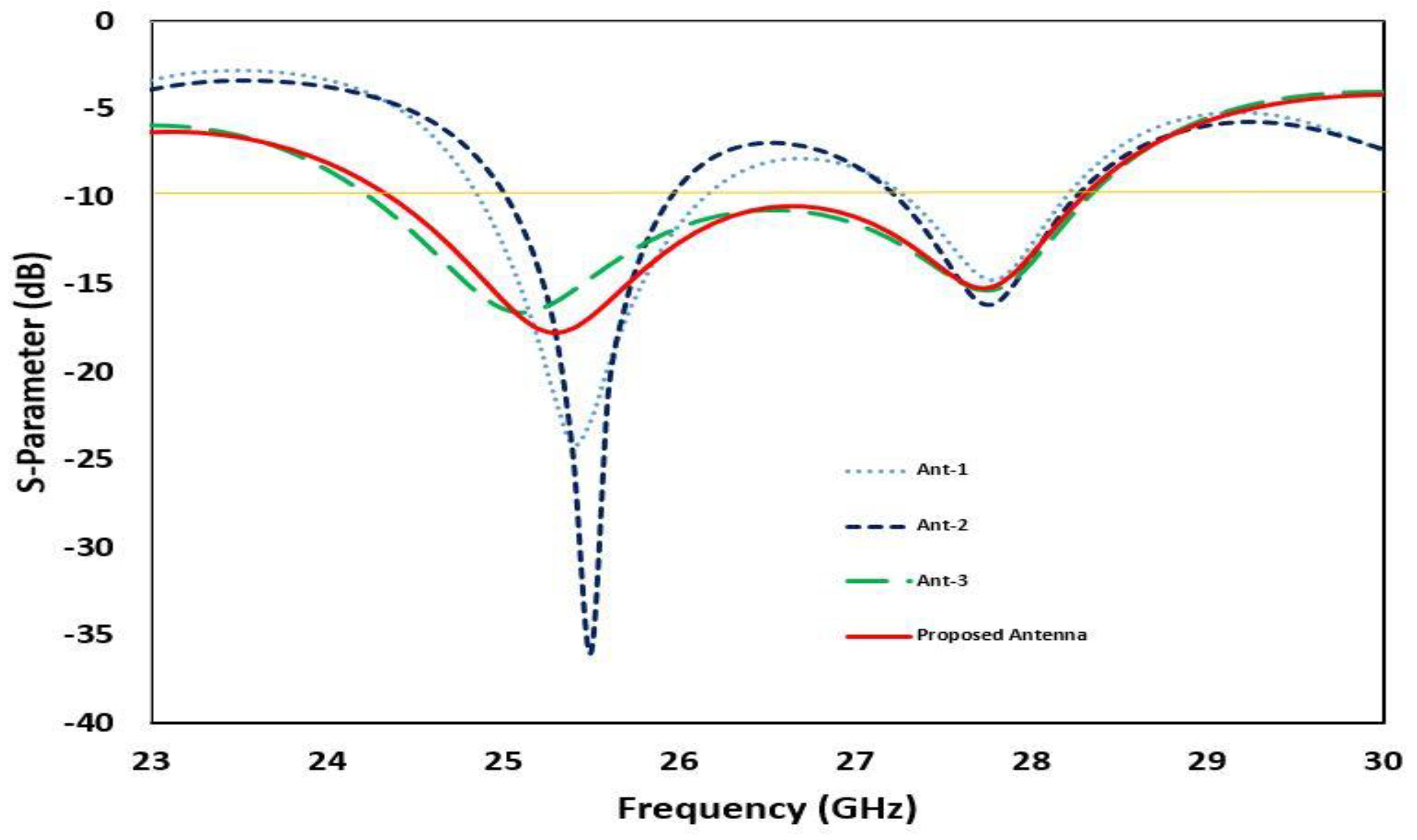
Figure 5.
Simulation results of SRR-based C-Shaped Antenna: (a) Response of S11 Vs Frequency; (b) Response of Peak Gain Vs Frequency.
Figure 5.
Simulation results of SRR-based C-Shaped Antenna: (a) Response of S11 Vs Frequency; (b) Response of Peak Gain Vs Frequency.
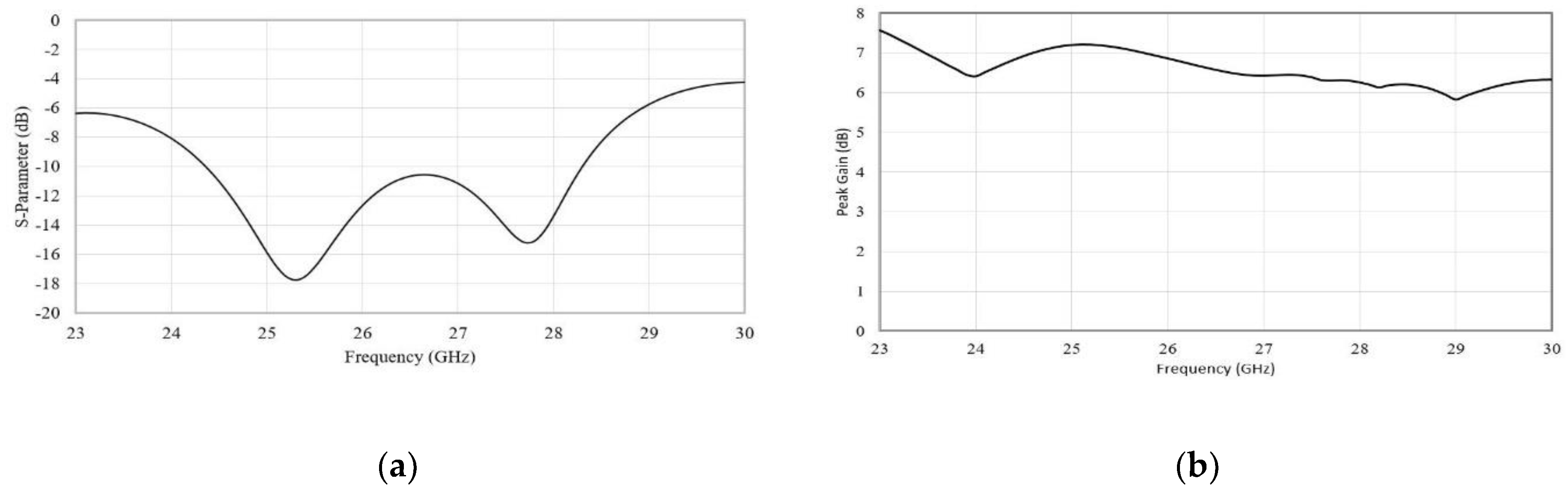
Figure 6.
3D radiation pattern results for Antenna 3 at :(a) 25.1 GHz and; (b) 27.8 GHz.
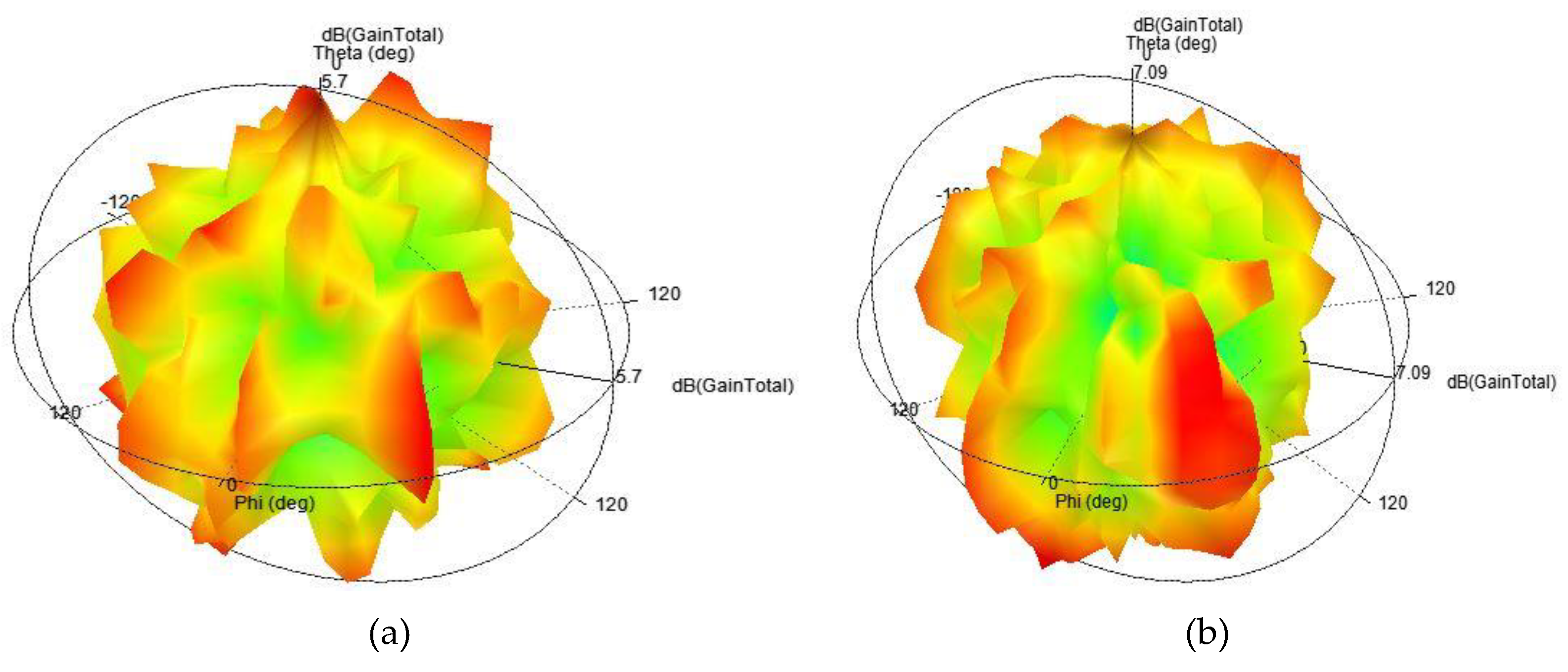
Figure 7.
3D radiation pattern results for the proposed antenna at :(a) 25.1 GHz and; (b) 27.8 GHz.
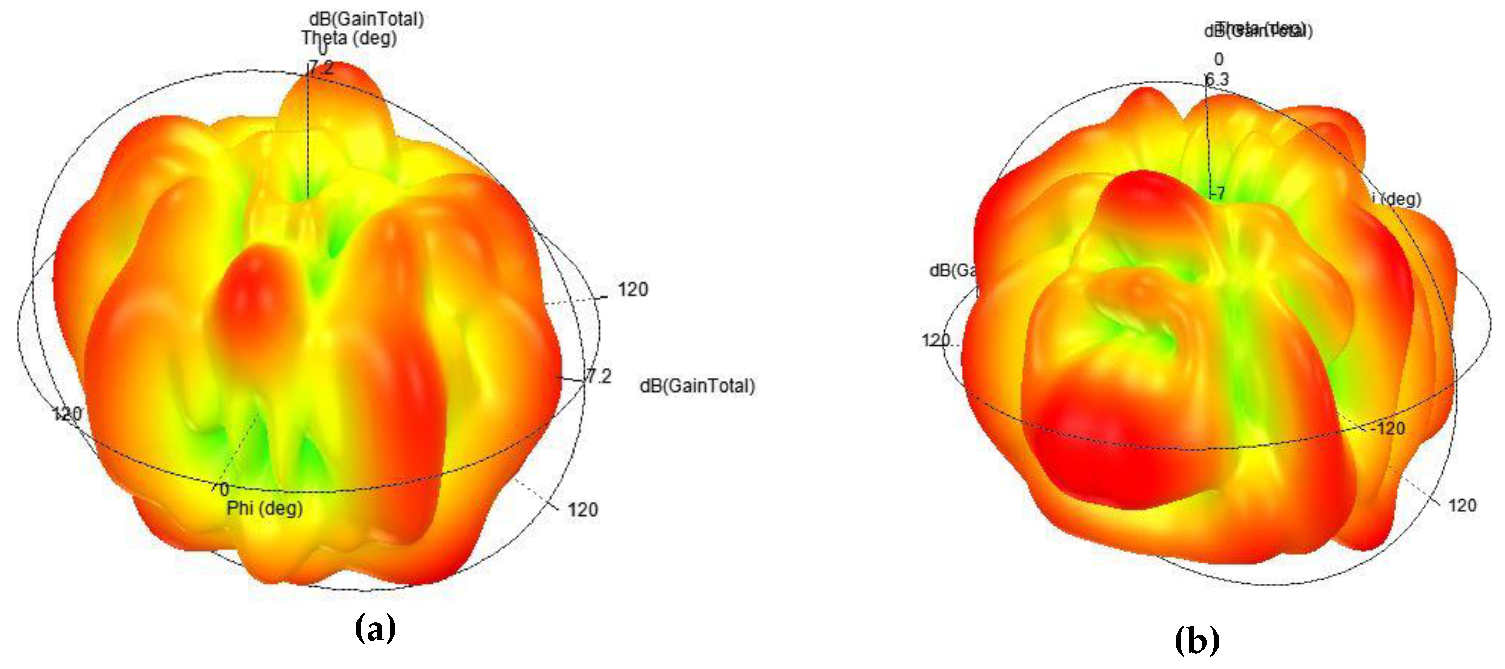
Figure 8.
Total efficiency and peak gain of the proposed Antenna.
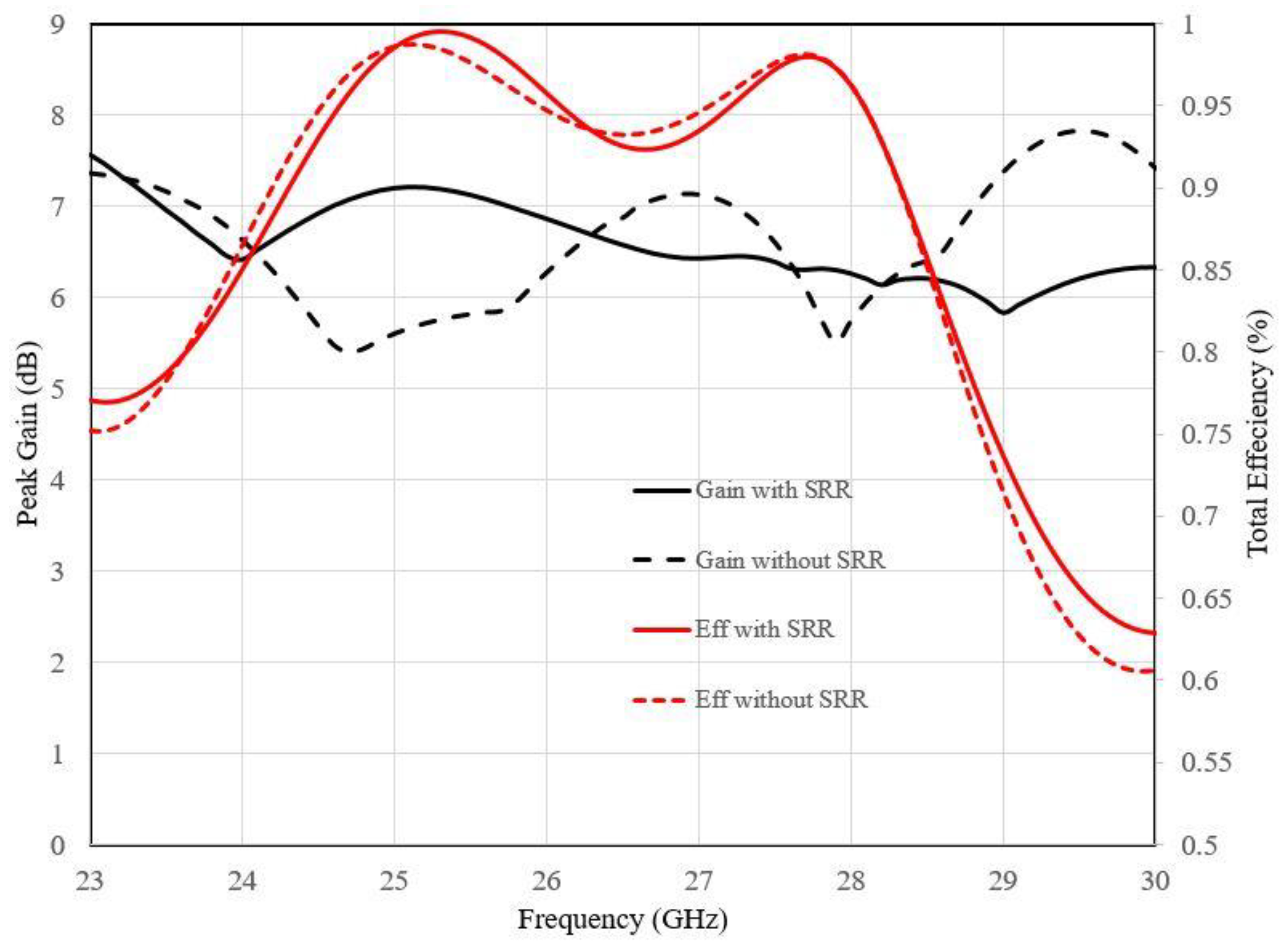
Figure 9.
Fabrication and Measurement Results of the proposed antenna: (a) Simulation and Measurement results of the Proposed Antenna; (b) Fabrication of the proposed antenna; (c) Measurement Set-up; (d) VNA Measured Results.
Figure 9.
Fabrication and Measurement Results of the proposed antenna: (a) Simulation and Measurement results of the Proposed Antenna; (b) Fabrication of the proposed antenna; (c) Measurement Set-up; (d) VNA Measured Results.
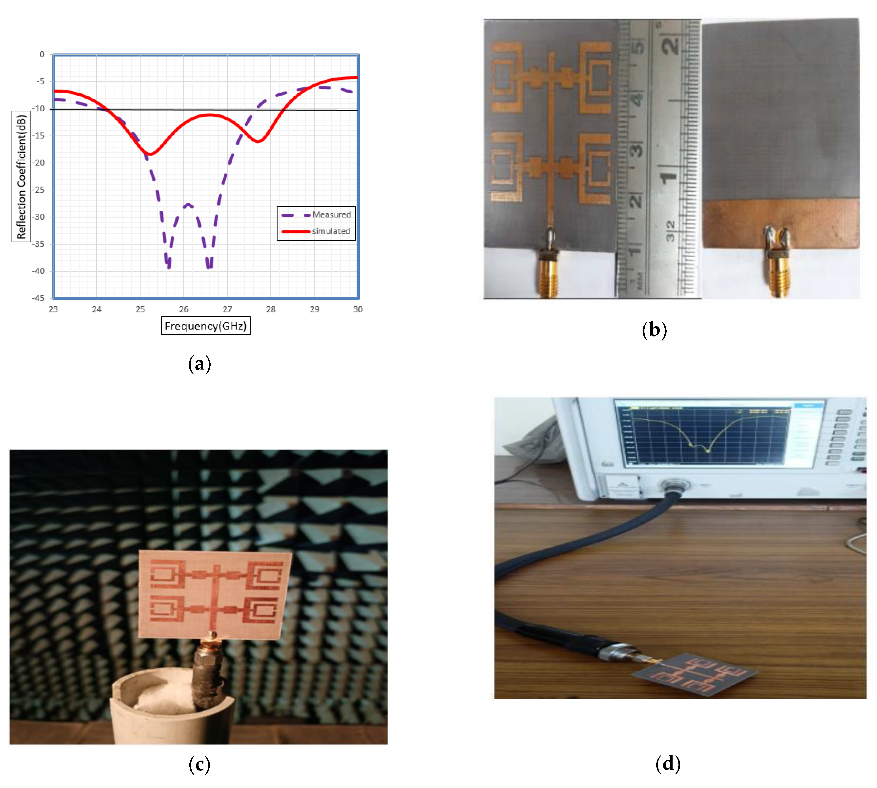
Figure 10.
The polar radiation patterns at xz-plane: (a) 25.2 GHz and; (b) 27.7 GHz.
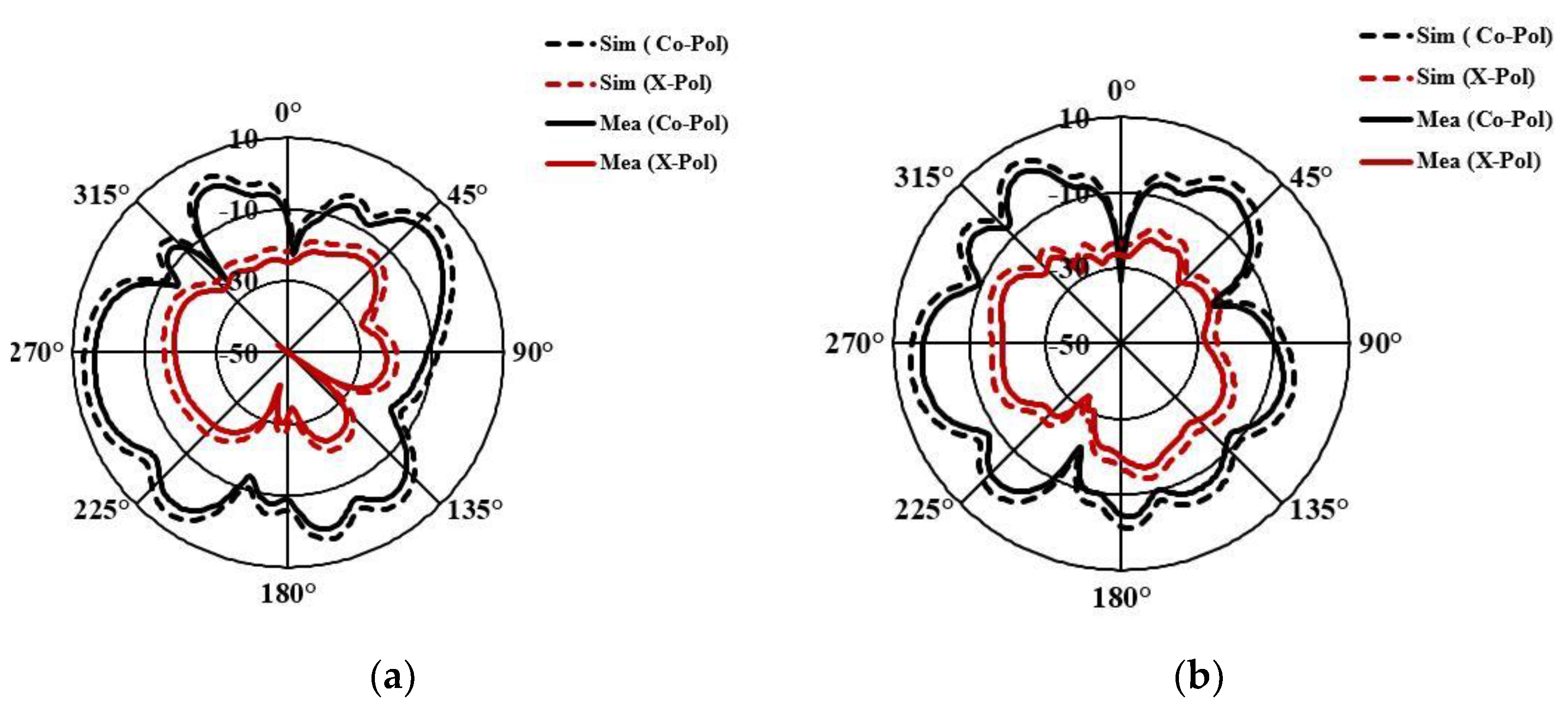
Table 2.
The evolution process of SRR based C-Shaped Antenna.
| Antenna Evolutions | 3D Model | S-Parameter | Gain Plot | 3D Plot |
|---|---|---|---|---|
| Antenna 1 | 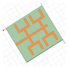 |
 |
 |
 |
| Antenna 2 | 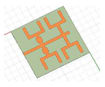 |
 |
 |
 |
| Antenna 3 | 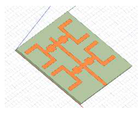 |
 |
 |
 |
| Proposed Antenna |  |
 |
 |
 |
Table 3.
Summary results of design evaluation.
| Antenna Steps | Operating Frequency(GHz) | S11 (dB) | B.W(GHz) | Peak Gain (dB) |
|---|---|---|---|---|
| Antenna-1 | 25.4 | -24.07 | 1.2 | 9.22 |
| 27.8 | -14.71 | 0.9 | ||
| Antenna-2 | 25.5 | -36.05 | 1 | 8.3044 |
| 27.8 | -16.06 | 1.1 | ||
| Antenna-3 | 25.1 | -16.6 | 4.1 | 7.1 |
| 27.8 | -15.29 | |||
| Proposed Antenna | 25.2 | -18.43 | 4.2 | 7.49 |
| 27.7 | -16.11 |
Table 4.
Comparison Results of Proposed Antenna.
| Type | Reflection Coefficient (dB) | Bandwidth (GHz) | Impedance Bandwidth (%) |
|---|---|---|---|
| Simulated | below -10dB | 4.2 | 16.03 |
| Measured | below -10dB | 3.5 | 13.4 |
Table 5.
Comparison of the proposed antenna performance with the existing models.
| Reference | Dimensions (LXW) (mm)² | Coverage bands (GHz) | Band width (GHz) | Peak gain (dBi) |
|---|---|---|---|---|
| [7] | 21x85 | 28 | 1.95 | 10.17 |
| [11] | 20x40 | 26.71-28.91 | 2.2 | 7 |
| [16] | 61x54 | 28 | 0.83 | 6.68 |
| [18] | 90x160 | 24.25-27.50 | 3.25 | 14 |
| [23] | 15x12.7 | 28 | 3 | 7 |
| [24] | 10x10 | 24.85 | 1.318 | 6.48 |
| Proposed Antenna | 43x45 | 24.1-28.3 | 4.2 | 7.49 |
Disclaimer/Publisher’s Note: The statements, opinions and data contained in all publications are solely those of the individual author(s) and contributor(s) and not of MDPI and/or the editor(s). MDPI and/or the editor(s) disclaim responsibility for any injury to people or property resulting from any ideas, methods, instructions or products referred to in the content. |
© 2023 by the authors. Licensee MDPI, Basel, Switzerland. This article is an open access article distributed under the terms and conditions of the Creative Commons Attribution (CC BY) license (https://creativecommons.org/licenses/by/4.0/).
Copyright: This open access article is published under a Creative Commons CC BY 4.0 license, which permit the free download, distribution, and reuse, provided that the author and preprint are cited in any reuse.


