Submitted:
01 August 2023
Posted:
02 August 2023
You are already at the latest version
Abstract
In this article, metallic additive manufacturing (AM) processes were classified and demonstrated. AM technology can be applied to a wide range of industrial areas because of its great feasibility in the design and manufacturing of various complex parts. The main factor that distinguishes various metallic AM processes from each other is the deposition method. Deposited metal can be imported in the form of melt or semi-solid. AM technology also covers a wide range of materials like aluminum, titanium, and many other alloys. Some of the common applications of metallic AM processes are the quick manufacturing of the parts which utilized in various industries like medical, automotive, aerospace, and jewelry industries. AM can help to fabricate parts that are impossible to be manufactured by other processes.
Keywords:
metal additive manufacturing
; metal 3D-Printing
; deposition
1. Introduction
The additive manufacturing process (or 3D-Printing), as a new and strategic process, has attracted considerable attention in the industry in recent years and as a result, has been growing drastically. Typically, AM is a layered manufacturing process [1,2,3] that includes forming and processing of material. It is worth noting that this process is fully computer-controlled [4].
According to ASTM 52900 [5], the additive manufacturing is defined as “a process of joining materials to make parts from 3D model data, usually layer upon layer, as opposed to subtractive manufacturing and formative manufacturing methodologies.”
Additive manufacturing is a process based on discrete stacking, which is controlled via software and a material control system. Generally, 3D-manufactured parts are made by stacking multiple layers. Hence, this process is so flexible that high-speed manufacturing can be achieved while having minimum material waste. One of the main advantages of AM process is the production of complex-structured parts which find application in aerospace, medical industries, etc. because traditional manufacturing processes for these specific parts are extremely limited. This extensive attention toward this process has motivated many researchers to develop new advanced metal additive manufacturing techniques [6,7,8,9]. A classification of metal AM methods is presented in Figure 1.
These processes have been classified with regard to various criteria such as the form of utilized material (e.g., wire, powder, etc.), types of heating sources (e.g., laser, arc, electron beam, etc.), build volume, etc. According to the above-mentioned classifications, metallic additive manufacturing processes can be divided into multiple methods like SLA, SLS, SLM, WAAM, etc. [2,10,11,12]. The main aim of this article is to present the classification and introduction of metal additive manufacturing based on the heating source, materials, and the deposition methods.
2. Material Jetting
Material Jetting (MJ) is a class of AM techniques; in which feedstock droplets of the material are selectively deposited [1].
2.1. Liquid Metal Jetting
Liquid Metal Jetting (LMJ) is a solid freeform fabrication technique for making metallic parts as well as electronic interconnects. It is a process similar to inkjet printing in which molten droplets are printed. By controlling the solidification speeds and the composition of the alloy, LMJ can create parts with outstanding properties. Liquid metal jet printing (LMJP) is an emerging manufacturing process that addresses several challenges in solid freeform fabrication (SFF). The method is based on the technology analogous to inkjet printing. Unlike the spray forming and spray deposition techniques that spray the materials in an uncontrolled manner, the LMJP controls and dispenses every “single molten droplet” of the material to a determined location by computer-aided design (CAD) data. The possible applications of the LMJP involve the ability to quickly fabricate 3D electronic circuitry and mechanical parts [13,15,16].
There are two jetting techniques; drop-on-demand and continuous jetting. The schematics of these processes are shown in Figure 2. Continuous jetting is applied when the material is continuously jetted. A thin liquid jet is considered to be discontinuous if the jet breaking up happens, and then the formation of the droplets takes place at the orifice or nozzle of the jet. Table 1 depicts the differences between drop-on-demand and continuous methods and their applications [16,17].
2.2. Nano-particle inkjet printing
Inkjet printing is a deposition method used for liquid-phase materials. These materials or inks involve a solute-dissolved material or a dispersed material in a solvent. The technique essentially includes the ejection of a fixed amount of ink in a chamber from a nozzle and quasi-adiabatic reduction of the volume of the chamber via piezoelectric action. A chamber filled with the liquid is contracted in response to the utilization of an external voltage. This sudden reduction sets up a shockwave in the liquid, which makes a liquid drop eject from the nozzle. The schematic of this technique is depicted in Figure 3 [18]. The deposition process in inkjet printing may also be carried out continuously (as opposed to drop-wise deposition of the material) [8].
Nano-particles possess several exceptional properties that are different from the bulk material. The thermodynamic size lowers the melting point of nanoparticles compared to the bulk material. This property of the nanoparticles is very useful for flexible electronics. In order to obtain highly conducting printed tracks, metallic nanoparticles such as gold, silver, and copper are utilized. Silver nanoparticles become an appropriate material for ink formulation compared to gold especially for obtaining low cost, low resistivity, and low oxidation rate [7].
2.3. Aerosol Jet Printing
Aerosol Jet Printing (AJP) is the spraying of ink composed of small-size droplets which are dispersed in the liquid (Figure 4). The technique involves two components: an atomizer and a deposition head. The atomizer is a pneumatic or ultrasonic device that produces a dense vapor of droplets. A carrier gas like nitrogen moves [10] across the atomizer in order to transfer the dense vapor into the section of the deposition head. The resulting material flow leaves the head from a nozzle onto the substrate. This process is suited for 3D utilizations because the deposition head could be mounted to a 5-axis positioning stage to follow the substrate contour at 1 to 5 mm of fixed distance. Furthermore, it is achievable to acquire fine characteristics because the aerosol involves a large density of micro-droplets, which are focused on fabricating lines by thickness values of about 10 μm [11,24,25].
3. Powder Bed Fusion
Powder Bed Fusion (PBF) methods are based on coating a metal powder layer with a thickness of 20 to 200 microns on a platform and then scanning the powder bed with a source of heat that melts and then solidifies the powder along the beam path. The layer-by-layer laser scanning is managed by the CAD program of the part being manufactured. Figure 5 depicts the schematic steps of this process [14,28].
3.1. Selective Laser Melting
Selective Laser Melting (SLM) is one of the PBF processes which are the most widely utilized in AM industries. A layer of metallic powders is utilized to coat the building platform on the substrate or the previously deposited layer by a blade and then melted by a laser beam. The laser beam melts the powders as programmed by the CAD data. Afterward, the building platform moves to the downside and then a new layer of the powder is subjected to the laser. The technique is repeated until the height of the part is completed. The thickness value of each layer varies from 15 µm to 150 µm. Several parameters have to be considered carefully to produce a defect-free sample. Some of the important parameters are laser scan speed, laser power, hatch overlaps, hatch distance, and hatch style, which have an important influence on the mechanical properties of the produced parts. The process is performed inside a chamber. The chamber is filled with Ar or N2 as inert gases. The used gas depends on the metal powder reactivity. Moreover, the chamber is subjected to overpressure situations. The presence of the inert gas in the chamber reduces the oxidization during this process. The substrate plate is preheated between 200 °C to 500 °C to minimize the solidification rate in the produced part [29,30,31]. The schematic of the SLM process is depicted in Figure 6.
3.2. Electron Beam Melting
The Electron Beam Melting (EBM) process (Figure 7) applies the electron beam energy in order to melt the metallic powders. Each layer is provided by the following steps:
- ✓
- Spreading the metallic powder.
- ✓
- Preheating and then sintering the powder with a defocused beam which gives mechanical stability as well as electrical conductivity to the metallic powder layer.
- ✓
- Melting the powder by using a focused beam.
- ✓
- Lowering of the building platform by the thickness of 1 layer that may vary from 50 µm to 200 µm.
The process is occurred in a vacuum with a pressure of roughly 10−5 mbar and at high temperatures. The materials produced with EBM have microstructural features better than that of wrought and cast materials because this method produces stress-relieved materials with microstructures free from martensitic features. The helium gas with a partial pressure of 2 × 10⁻³ mbar is introduced to the EBM chamber during the melting process to protect the chemical specification of produced material. Therefore, EBM is suited for the production of materials with a high affinity to reacting with O2 such as Ti alloys [28,32,33].
3.3. Direct Metal Laser Sintering
Direct Metal Laser Sintering (DMLS) is an advanced laser-based additive manufacturing process that utilizes the 3D design data to create a part by a layer-by-layer consolidation route. DMLS initiates using the application of a thin layer of metallic powder on the platform. As depicted in Figure 8, a laser beam with high power liquid-phase-sinters each layer of the powder. Afterward, the build platform moves on lowering, and then the re-coater blade spreads the powder on the platform after each scanning. Because of its flexibility in shapes and feedstock, this process provides great potential for producing complex products that cannot be manufactured by other methods. DMLS is a much more effective process among different types of AM processes which can manufacture any complex shape. The other advantage of DMLS is less wastage of powder materials used [34,35].
3.4. Selective Laser Sintering
The Selective Laser Sintering (SLS) technique is a process that fabricates layers with predesigned geometry through sintering the powders with the laser beam (Nd-YAG or CO2). The technique follows as: (1) the substrate is moved down to a depth equal to the thickness of the layer; (2) a layer of powder is rolled out on the substrate; (3) the deposited layer of powder is scanned by the laser to sinter powders at determined area. The stages 1, 2, and 3 are repeated until the designed sample is completed. A schematic of SLS is depicted in Figure 9 [36,37,38].
4. Binder Jetting
Binder Jetting (BJG) is an AM technology capable of handling alloys such as Al-, Cu-, Fe-, Ni-, and Co-based alloys as well as ceramics such as glasses, sand, and graphite. However, this process could use any material which is available in powder form and allows the color printing. This process applies two materials; one is the ceramic/metal-based material of which the part is to be built, and the other is the binder material, which glues the ceramic/metal powder material within and between the layers [30]. The binder is normally liquid, while the ceramic/metal powder is in the form of a solid. In this process, the ceramic/metal powder is firstly spread on a substrate, and then a layer of the binder is deposited on the ceramic/metal layer. This is performed by the CAD model. The BJG process includes some post-processing such as infiltration, sintering, de-powdering, curing, and finishing. The post-processing usually takes a longer time compared with the actual printing especially in the sintering part. One of the important advantages of this process is that the products can be manufactured without support structures [40].
As BJG utilizes binders as the adhesive materials, the characteristics of the material are not always suitable for the automobile and aerospace applications because the binder could lead to the porosity formation in the conventional sintering techniques. The speed of this process is faster than that of the EBM/SLM techniques and could be accelerated by the increase of the number of the print-head holes which deposit the binder and the material. It also lets the two-material approach, in which different binder-powder combinations lead to various mechanical properties by changing the binder-powder ratio [41,30]. The process schematic is depicted in Figure 10.
In this process, a powder layer is first spread by a counter-rotating roller. Then, the inkjet printing head sprays the liquid agent on the bed in order to fabricate the 2D pattern for each layer. Some powder/binder systems may utilize heaters in order to control the curing and moisture. However, the heat is not a basic requirement in the process. After making each layer, the build platform is moved down to provide the room for the next layer. As-printed parts are normally brittle and usually are subjected to the post-processing to improve their mechanical properties [43,44].
Nowadays, much percentage of industrial BJ manufacturing is associated with metallic materials. A large number of these processes focus on the powder metallurgy of alloys like stainless steels. Many industrial applications need high-density alloys. Although high densities have been obtained in different materials, it is still a challenge to decrease defects and provide geometric accuracy. The maximum level of density obtained for the steel powders after the sintering is about 92-95%. Hot-Isostatic Pressing (HIP) process is a technique to densify the powder-based products to over 99% density [43,42].
5. Cold Spray Additive Manufacturing
Cold Spray Additive Manufacturing (CSAM) is a process in which solid-state particles are delivered to the substrate through a carrier gas with a supersonic speed to deposit a layer on the substrate. Figure 11 shows the schematic of the process. High velocity is an essential requirement for the particle deposition and achieving dense coating. Parameters such as nozzle geometry, particle characteristics, and gas conditions affect the velocity. The deposition happens at low temperatures. This process is suitable for thermally-sensitive coatings such as nano-crystalline, amorphous materials, and oxygen-sensitive materials like titanium, aluminum, and magnesium composites. The application of this process is the surface upgrading of metals in order to increase the wear and corrosion resistance and thermal/electrical conductivity. This technique is also appropriate for obtaining coatings on light metals such as Mg alloys because of its low temperature-tolerance. The process can be designed in either manual or automated operation mode. Gases with aerodynamic properties such as N2, He, combinations of N2 and He, and dry air (21% O2 + 79% N2) are used in this process [45–47]. The main components of the process include:
- ✓
- Powder feeder and spray gun;
- ✓
- Gas source;
- ✓
- The pre-nozzle entry of the gas heater to compensate for the cooling due to fast nozzle expansion;
- ✓
- Supersonic nozzle;
- ✓
- Spray chamber with a motion mechanism;
- ✓
- Monitoring and controlling the gas temperature and pressure of the spraying.
Figure 12 represents cold spray components. Compressed gases like He, O2, and N2 pass through a system that consists of a powder feeder and a gas heater at pressure values in the range of 1.4–3.4 MPa, which is maintained at about 1.7 MPa. The gas is heated electrically between 100-600 °C and then travels across a diverging/converging nozzle till it reaches the supersonic speed. The powder is subjected to the stream of the gas before the converging zone of the nozzle. The extending gas accelerates the process. A decrease in the temperature happens in the middle of the supersonic expansion of the nozzle. Consequently, the temperature of the gas stream is almost below the melting point of the particles, which develops a solid-state coating from particles without any oxidation [46,48].
The cold spray technique could be divided into two classes based on the propulsive gas pressure: high-pressure cold spray (more than 1 MPa) and low-pressure cold spray (less than 1 MPa). Figure 13(a) depicts a schematic of a high-pressure cold spray process. Compressed gas is separated into two streams before entering the spray system. One stream which is named propulsive gas passes across a gas heater and is heated to high temperature. The second stream which is named carrier gas passes across the powder feeder, where it is loaded with the feedstock. Then, these gas streams are mixed before entering the nozzle and expanding to produce a supersonic gas and also a powder stream. Figure 13(b) represents a schematic of a low-pressure cold spray process [49,47].
6. Hybrid Metal Extrusion & Bonding Additive Manufacturing
Hybrid Metal Extrusion & Bonding Additive Manufacturing (HYB-AM) is a new solid-state technique that uses metal feedstock wire to deposit the material in a stringer-like manner in order to form layers and produce a net-shape structure. After the deposition, the produced part is finished by the machining to create the desired net shape [50].
The flow of the material in this process is based on continuous rotary extrusion, which is also recognized as Conform extrusion. The extrusion sequence involves two steps. In the first step, the feedstock is deformed in the extruder. This step causes the oxides present on the surface of the feedstock to become dispersed into the extrudate. In the second step, the extruder supplies the pressure to acquire bonding at the interface between the underlying structure and the extrudate. According to Figure 14(a), the extrusion pressure is produced by the frictional force between the tapered groove and the feedstock wire in the rotating wheel. The feedstock is pressed into the groove and also driven forward by the wheel rotation. Then, the feedstock wire is blocked by the abutment, and axial compression is induced. This causes the material to be yielded and fill the cross-section. This enhances the contact surface and also the friction, leading to a build-up in further pressure and causing the material to be flowed out of the die. Figure 14(b) represents the HYB-AM deposition process. The extruder adds the material as these shifts in the deposition direction and places stringers side by side to create a layer. Then, it allows new layers to be built on top of the material. The die is constantly scrapping the underlying layer top during deposition and then the adjacent stringer side wall removes the surface oxide. Before the deposition, a metal strip is fixed on the heated bed to behave as a substrate on the first layer of the material deposited. In the HYB-AM process, the merging metal streams must be considered as the mating streams of substrate and extrudate, as shown in Figure 15 [51,52].
7. Sheet Lamination
The sheet lamination processes used in metal additive manufacturing are divided into three categories; Ultrasonic Additive Manufacturing (UAM), Friction Stir Additive Manufacturing (FSAM), and Friction-Forging Tubular Additive Manufacturing (FFTAM) techniques [53].
7.1. Ultrasonic Additive Manufacturing
The UAM technique uses metallic sheets, which are bound together by using ultrasonic welding. Different alloys used in this process include copper alloys, aluminum alloys, titanium alloys, and stainless steels. The process happens at a low temperature. One advantage of this process is that the technique can bond different materials, and it requires little energy. The alloy is not melted. The layers are bonded together using a combination of ultrasonic oscillation and pressure [54].
This process which also known as Ultrasonic Consolidation (UC) is a hybrid process that combines ultrasonic metal seam welding and computer numerical control (CNC) milling. In this method, the part is built up on a base plate which is rigidly bolted onto a heated platen. The temperature of this platen ranges from room temperature to approximately 200 oC. Parts are manufactured in a bottom-to-top manner, and each layer is built up of metal tape-like foils laid side by side and then cut utilizing CNC. As depicted schematically in Figure 16, in this process, a rotating sonotrode advance along the length of a thin metal foil (usually 100–150 μm thick) while applying a normal force to the new layer, keeping it in close contact with the base plate or previous layer. This ultrasonic oscillatory force is applied transversely to the direction of motion at a constant frequency of 20 kHz and a user-set amplitude. After the deposition of a foil, another foil is deposited just right next to the previous one. This process is repeated until the completion of a layer. All these deposited layers experience the same procedure. Each level of UAM consists of four layers of deposited metal foils. After the deposition of one level, the CNC head cuts the deposited layers to their contour. It should be noted that the geometry of the part dictates the contouring procedure. The consecutive addition-subtraction of layers is continued until the final geometry of the part is achieved. Furthermore, each layer is deposited as an assemblage of foils laid side by side rather than a single continuous sheet, unlike the other sheet lamination processes [53,55].
7.2. Friction Stir Additive Manufacturing
FSAM falls into the category of solid-state additive manufacturing processes that can be considered a combination of layer-by-layer AM and FSW processes. Owning to its exceptional ability for microstructural engineering and grain refinement, it can be useful in tuning microstructures to fit the customer’s requirements. It is reported that high-strength alloys can be fabricated using this process. In FSAM, the principle of layer-by-layer AM is employed. Hence, a stack of overlapping sheets/plates is penetrated by a consumable tool and the FSLW process is conducted along the defined direction. Figure 17 illustrates a schematic diagram for the FSAM process. Friction and plastic deformation in a workpiece create enough heat for the joining of the layers. The joint creation is made possible as a result of the heat generation, material transfer, and the consolidation of material from the front to rear parts of the tool. In addition to process parameters, the tool geometry during FSAM also partially defines the macroscopic and microscopic aspects of the manufactured parts [57,58,59].
The sequential steps carried out in the FSAM process are illustrated in Figure 18 and can be described as follows:
- The plates/sheets that are additively manufactured are prepared with regard to surface properties. These plates are made in the desired dimensions and degreased with acetone.
- Stacking metal sheets: In this step, two plates should be overlapped, one over the other, and oriented as desired.
- Performing a complete FSLW run: After the stacking of the two plates/sheets, FSLW is performed. After the first run, provided the required build height is achieved, the process will be finalized. Otherwise, the process will proceed to step 4.
- Flattening of upper build surface: If the required build height is not achieved, the deposition of new layers over the build is needed. Therefore, the upper surfaces of the previously fabricated layers are flattened in order to remove the flash developed during FSLW. After surface preparation, a new plate/sheet is placed over the top layer, and steps 2–4 are repeated until the desired height of the build is achieved [60].
7.3. Friction-Forging Tubular Additive Manufacturing
A solid-state, three-dimensional fabrication route similar to the FSAM process can be proposed in which the materials are plasticized; therefore, tubular structures can be deposited layer by layer. This newly invented processing route is referred to as friction-forging tubular additive manufacturing (FFTAM). The schematic representations of Figure 19(a)-(d) show different steps for layer-upon-layer deposition of metallic materials in the FFTAM method. As depicted in the schematic diagram of Figure 19(a), first of all, the powder mixture, in the form of prepared chips is inserted from the storage chamber into the free space in the central shoulder cavity via the screwing action of a rotating screw mandrel. After inserting the material, the main hollow cylindrical punch with a groovy surface will forge the powder and consolidate it via rotational movement, as represented in the schematic plot of Figure 19(b). Through conducting such thermomechanical treatment, the powder mixture or chips will be plasticized drastically and form a solid layer. In order to apply the maximum shear strain at an elevated temperature, the rotational directions for the main outer hollow shoulder/sheath and cylindrical punch have to be in the opposite direction with respect to each other. Chip consolidation can be enhanced at high temperatures and shear strains through a deformation-assisted diffusion mechanism under hydrostatic pressure. It should be pointed out that in the constant heat input, excessive ejection of the powder mixture/chips can result in the unsuccessful deposition of layers caused by incomplete solidification of feeding material. On the other hand, lower amounts of feeding powder mixture/chips for each layer can lead to overheating along the thickness and induce hot cracking between them. Therefore, the feeding powder volume is a critical parameter. The optimization of rotational speed for the primary outer shoulder, visceral punch, and the number of feeding chips per deposition layer is obtained via several trials and errors. According to Figure 19(a), it is possible to manufacture a short tube through several passes of the layer-upon-layer deposition process [57].
8. Direct Energy Deposition
3D cladding and 3D welding are the main techniques in the direct energy deposition (DED) AM process. In 3D cladding, a laser or plasma beam melts the metal powder ejected from the feeding nozzle in order to form a layer. 3D welding also called shaped metal deposition (SMD) is a wire-based process in which a small-diameter wire is fed and melted, binding to the previous layers via welding. There are different types of direct energy deposition systems including powder-feed and wire-feed-based DED (based on the type of feedstock), melt-based DED, and kinetic energy-based DED (based on the type of the energy source). The melting DEDs can be categorized based on the plasma, laser, electric arc, and electron beam. The flowchart in Figure 20 shows the different DED classes. Some important points can be given as:
- The DED process takes place during several stages, which include placing a substrate on the work table.
- In the case of using the laser process, the chamber of the device is filled with inert gas, and in the case of using the electron beam process, a vacuum is used to reduce the oxygen level in the chamber.
- At the beginning of the process, the laser or electron beam creates a molten pool on the surface. The material transfer is done by a nozzle (laser as powder and beam as wire). The nozzle and the beam move along the path determined by the CAD data.
8.1. Powder Feed Systems
Figure 21 depicts a schematic of the DMD technology (laser-based metal deposition). Utilizing the powder feeders, numerous organizations have tried to develop powdered DED machines, which are also known as laser-engineered net shaping (LENS), direct metal deposition (DMD), and laser consolidation (LC). Even though the general method seems to have no variation, subtle nuances have been distinguished including the laser powder, laser spot size, laser type, powered delivery method, inert gas delivery method, feedback control scheme, and/or a type of motion control. The final parts seem to acquire a dense structure during the build process because all these processes are comprised of the deposition, melting, and solidification of powdered material consuming a traveling melt pool. A wide range of lasers have been utilized in the laser-based processes including CO2 laser, Nd: YAG laser, diode lasers, and the fiber laser. The LENS process was originally developed by Sandia national laboratories in 1997 and then licensed to Optomec (USA), whereas the DMD process was jointly developed by the POM group and the University of Michigan. DMD and LENS technologies also offer the ability to deposit multiple materials in a single built and the ability to add metal to existing parts [44,63,64,65].
Accufusion laser consolidation is quite analogous to the LENS process, where a powder is deposited into a molten metal bath using a laser which provides the required energy for the deposition. Similar to the LENS method, the laser consolidation is carried out in a tightly sealed chamber. This process produces better as-built surface finishes than the LENS systems, however it suffers from lower deposition rates. Table 2 is a list of equipment manufacturers and the specifications of their equipment [66].
8.2. Wire Feed System
The volume of the deposit always equals the volume of the fed wire in the wire feeding, and there is near-unity feedstock capture efficiency (if the “splatter” from the melt pool is neglected). At the simple geometries, “blocky” geometries are without many thin/thick transitions and most effective coatings are mainly fabricated by wires [67,68].
8.2.1. Wire-Arc Additive Manufacturing
Wire-Arc Additive Manufacturing (WAAM) is one of the modern methods among the additive manufacturing processes of metals and is also known as shaped metal deposition (SMD) or rapid plasma deposition (RPD). The schematic of this process is demonstrated in Figure 22. The main components of the WAAM system include a wire feeding, welding torch, power source, and computer system, which are used to control the arc, deposition rate, and the wire feeding [10].
In the WAAM process, three methods are conventional to provide the heat input, which includes the metal inert gas (MIG) welding, tungsten inert gas (TIG) welding, and the plasma arc welding (PAW). Among these methods, using the MIG process is easier and more convenient than the other two methods because of the connection of the wire with the welding torch. In PAW and TIG, an external system is required to transfer the wire [68,69].
8.2.2. Wire-Laser Additive Manufacturing
Wire-Laser Additive Manufacturing (WLAM) is capable of producing full-density metal using metal wires as the additive material and the laser source energy. The WLAM system is composed of multiple parts, a laser, an automatic wire-feeding system, and a computer-controlled worktable. As shown in Figure 23, the laser generates a melt pool and molten wire metal simultaneously. Then, by feeding the molten wire to the melt pool a metallurgical bound with the substrate can be formed. By movement of the laser processing head and the wire feeder on the substrate, a bead-shaped solid is formed. The performance in the WLAM process is determined by many terms like surface finish, geometry and the quality of the deposit, the final microstructure of the deposited layer, and resulting mechanical properties [69,70,71].
8.2.3. Electron Beam Additive Manufacturing
Electron Beam Additive Manufacturing (EBAM) can create and sustain a molten pool using a focused electron beam in a high-vacuum chamber. It is worth noting that the feeding material in this process is mainly wire metal. CNC sequencing offers a singular or integral combination of movement involving a part, electron beam, or wire feeder, which facilitates the forming of complicated structures. The main advantage of EBAM compared to other DED technologies is the prevention of the surface oxidation which leads to higher purity of deposited layers. Another benefit of this process is superior and faster beam control through electromagnetic lenses, which eases the deposition rate increase in electrically conductive materials even in highly reflective alloys such as aluminum and copper, and improves the sensitivity index. The sensitivity index is defined as the ratio of component volume and the size of the actual deposition (Figure 24) [69,72,73].
9. Electrochemical Methods
It is reported that currently, there are two electrochemical metal-AM processes, electro-chemical fabrication (EFAB) and Fluid FM 3DP.
9.1. Electrochemical Fabrication
Electrochemical Fabrication (EFAB) is a recent solid free-form fabrication (SFF) process with high economic efficiency for fabricating prototypes or different parts on a massive scale. EFAB generates a whole layer simultaneously versus serially, like most SFF processes. EFAB can be utilized to form structures from electrodepositable metals. Based on the electrodeposition, EFAB can deposit ultra-thin layers (2-10 µm or thinner) with minimized stairsteps, which leads to a fully-dense metal structure with the possibility of being homogeneous and isotropic. The minimum deposited linewidth is about 25 µm, which can be further reduced. Electrochemical fabrication can be used to fabricate micromachines and micro-electro-mechanical systems (MEMS), offering high efficiency and considerable advantages over current processes including true 3-D geometry, compatible IC, process automation, and low capital investment. In order to build 3D micro-objects with the EFAB method, layer-by-layer electrochemical deposition, and subtractive planarization are used. Each layer deposition involves three main steps: electroplating of sacrificial support material through a special method known as “instant masking”, electroplating of build material, and planarization. The steps for the fabrication of metal parts in the EFAB method are illustrated in Figure 25. By placing the first layer as a sacrificial metal, all devices will be fully separated from the substrate. It should be pointed out that this method is usually used for medical devices. Currently, the EFAB process is compatible with three fully-commercialized and specific materials like Valloy™-120, nickel-cobalt alloy, palladium, Edura™-180, and a rhodium (Rh) formulation. These materials can be used for a wide range of applications because of their diverse functionality. It is worth noting that it is possible to use other materials in the EFAB process depending on the final application requirements [75,76].
9.2. Fluidic Force Microscope
Cynosure AG has recently developed an electrochemical technique known as the Fluidic Force Microscope (Fluid FM) process. In this process, electrodeposition, scanning probe microscopy (SPM), and precise liquid ink dispense the coalesce. This technique makes the use of atomic force microscopy (AFM) cantilevers with a microfluidic channel and a hollow tip. The electrolyte solution contained in a reservoir is pushed through the cantilever and out of the tip via the application of the pressure by a microfluidics control system (Figure 26). The tip is part of the printing head that can move in three dimensions inside the buffer bath. The metal cations are deposited to form the solid metal through the application of a proper potential to the built substrate. A real-time feedback system is employed for the detection of any tip deflection. As the formation of a voxel is completed, the upper face of the voxel interacts with the tip, exerting a force that leads to a few-nanometer deflection of the cantilever. When the deflection reaches a certain amount, the voxel is considered to be printed, and the tip moves to the next voxel [14,77].
Summary
Metal additive manufacturing processes are relatively new methods that allow the production of complex structures. In this review, AM processes were categorized based on their deposition methods, and then they were investigated from a broad perspective by focusing on the process steps, materials, and heat source types. In AM processes, feeding materials can exist in many forms such as powder, bulk wire, foil, etc. The feeding system, even for a single type of the feed material, may vary from one process to another. Computer control systems play an important role in automating of the AM processes resulting in higher surface quality and geometrical accuracy. Some advanced technologies of the heat sources such as laser beam, electron beam, and laser–arc hybrid used in these methods make them an interesting spectrum of solutions for the manufacturing challenges.
References
- Katz-Demyanetz, V. V Popov, A. Kovalevsky, D. Safranchik, and A. Koptyug, “Powder-bed additive manufacturing for aerospace application: Techniques, metallic and metal/ceramic composite materials and trends,” Manuf. Rev., vol. 6, 2019. [CrossRef]
- N. Guo and M. Leu, “Additive manufacturing: Technology, applications and research needs,” Front. Mech. Eng., vol. 8, Sep. 2013. [CrossRef]
- Y. Song, Y. Yan, R. Zhang, D. Xu, and F. Wang, “Manufacture of the die of an automobile deck part based on rapid prototyping and rapid tooling technology,” J. Mater. Process. Technol. - J MATER Process TECHNOL, vol. 120, pp. 237–242, Jan. 2002. [CrossRef]
- N. Asnafi, “Metal Additive Manufacturing—State of the Art 2020,” Metals (Basel)., vol. 11, p. 867, May 2021. [CrossRef]
- T. Method, “ISO/ASTM 52900-Standard Terminology for Additive manufacturing–general principles–terminology.,” vol. i, pp. 1–9, 2015.
- F. He, et al., “Research and application of artificial intelligence techniques for wire arc additive manufacturing: a state-of-the-art review,” Robot. Comput. Integr. Manuf., vol. 82, p. 102525, 2023. [CrossRef]
- M.J. Mirzaali, V. Moosabeiki, S.M. Rajaai, J. Zhou, and A.A. Zadpoor, “Additive Manufacturing of Biomaterials—Design Principles and Their Implementation,” Materials, vol. 15, no. 15. 2022. [CrossRef]
- Lyons, “Additive manufacturing in aerospace: Examples and research outlook,” Bridg., vol. 44, no. 3, 2014.
- 9. M. Ni, et al., “Microstructure and mechanical properties of additive manufactured Inconel 718 alloy strengthened by oxide dispersion with 0.3 wt% Sc addition,” J. Alloys Compd., vol. 918, p. 165763, 2022. [CrossRef]
- S. Singh, S. kumar Sharma, and D.W. Rathod, “A review on process planning strategies and challenges of WAAM,” Mater. Today Proc., vol. 47, pp. 6564–6575, 2021. [CrossRef]
- M. Yakout, M. Elbestawi, and S.C. Veldhuis, “A Review of Metal Additive Manufacturing Technologies,” Solid State Phenom., vol. 278, pp. 1–14, Jul. 2018. [CrossRef]
- Y. Chen, et al., “Laser powder deposition of carbon nanotube reinforced nickel-based superalloy Inconel 718,” Carbon N. Y., vol. 107, pp. 361–370, 2016. [CrossRef]
- T.Y. Ansell, “Current Status of Liquid Metal Printing,” Journal of Manufacturing and Materials Processing, vol. 5, no. 2. 2021. [CrossRef]
- M. Vaezi, P. Drescher, and H. Seitz, “Beamless Metal Additive Manufacturing,” Materials, vol. 13, no. 4. 2020. [CrossRef]
- T. Wang, T.-H. Kwok, and C. Zhou, “In-situ Droplet Inspection and Control System for Liquid Metal Jet 3D Printing Process,” Procedia Manuf., vol. 10, pp. 968–981, 2017. [CrossRef]
- J.W. Priest, C. Smith, and P. DuBois, “Liquid Metal Jetting for Printing Metal Parts,” Proc. 8th Solid Free. Fabr. Symp., pp. 1–9, 1997.
- Hill, “liquid metal 3D printing,” Transplantation, vol. 97, no. 12, p. 1200, 2014.
- M. Singh, H.M. Haverinen, P. Dhagat, and G. E. Jabbour, “Inkjet printing-process and its applications,” Adv. Mater., vol. 22, no. 6, pp. 673–685, 2010. [CrossRef]
- L. Nayak, S. Mohanty, S.K. Nayak, and A. Ramadoss, “A review on inkjet printing of nanoparticle inks for flexible electronics,” J. Mater. Chem. C, vol. 7, no. 29, pp. 8771–8795, 2019. [CrossRef]
- N.C. Raut and K. Al-Shamery, “Inkjet printing metals on flexible materials for plastic and paper electronics,” J. Mater. Chem. C, vol. 6, no. 7, pp. 1618–1641, 2018. [CrossRef]
- B.K. Lee, Y. H. Yun, J.S. Choi, Y.C. Choi, J.D. Kim, and Y.W. Cho, “Fabrication of drug-loaded polymer microparticles with arbitrary geometries using a piezoelectric inkjet printing system,” Int. J. Pharm., vol. 427, no. 2, pp. 305–310, 2012. [CrossRef]
- M. Alhendi, R.S. Sivasubramony, D.L. Weerawarne, J. Iannotti, P. Borgesen, and M.D. Poliks, “Assessing Current-Carrying Capacity of Aerosol Jet Printed Conductors,” Adv. Eng. Mater., vol. 22, no. 11, p. 2000520, Nov. 2020. [CrossRef]
- Capel, et al., “Digitally Driven Aerosol Jet Printing to Enable Customisable Neuronal Guidance,” Front. Cell Dev. Biol., vol. 9, Aug. 2021. [CrossRef]
- M. Seiti, O. Degryse, and E. Ferraris, “Aerosol Jet® printing 3D capabilities for metal and polymeric inks,” Mater. Today Proc., vol. 70, pp. 38–44, 2022. [CrossRef]
- D.E. Kravchenko, A. Matavž, V. Rubio-Giménez, H. Vanduffel, M. Verstreken, and R. Ameloot, “Aerosol Jet Printing of the Ultramicroporous Calcium Squarate Metal–Organic Framework,” Chem. Mater., vol. 34, no. 15, pp. 6809–6814, Aug. 2022. [CrossRef]
- Carrozza, A. Aversa, P. Fino, and M. Lombardi, “A study on the microstructure and mechanical properties of the Ti-6Al-2Sn-4Zr-6Mo alloy produced via Laser Powder Bed Fusion,” J. Alloys Compd., vol. 870, p. 159329, 2021. [CrossRef]
- N.D. Dejene and H.G. Lemu, “Current Status and Challenges of Powder Bed Fusion-Based Metal Additive Manufacturing: Literature Review,” Metals, vol. 13, no. 2. 2023. [CrossRef]
- M. Leary, “Design of titanium implants for additive manufacturing,” in Woodhead Publishing Series in Biomaterials, F. H. Froes and M. B. T.-T. in M. and D. A. Qian, Eds. Woodhead Publishing, 2018, pp. 203–224.
- F. Trevisan, et al., “Additive manufacturing of titanium alloys in the biomedical field: processes, properties and applications,” J. Appl. Biomater. Funct. Mater., vol. 16, no. 2, pp. 57–67, 2018. [CrossRef]
- P.K. Gokuldoss, S. Kolla, and J. Eckert, “Additive manufacturing processes: Selective laser melting, electron beam melting and binder jetting-selection guidelines,” Materials (Basel)., vol. 10, no. 6, 2017. [CrossRef]
- B. Gao, H. Zhao, L. Peng, and Z. Sun, “A Review of Research Progress in Selective Laser Melting (SLM),” Micromachines, vol. 14, no. 1. 2023. [CrossRef]
- F. Trevisan, et al., “Additive manufacturing of titanium alloys in the biomedical field: processes, properties and applications” J. Appl. Biomater. Funct. Mater., vol. 16, Sep. 2017. [CrossRef]
- Gibson, D. Rosen, and B. Stucker, “Additive Manufacturing Technologies – Rapid Prototyping to Direct Digital Manufacturing”, vol. 5. 2010.
- J. Nandy, H. Sarangi, and S. Sahoo, A Review on Direct Metal Laser Sintering: Process Features and Microstructure Modeling, vol. 6, no. 3. Lasers in Manufacturing and Materials Processing, 2019.
- T. Grünberger and R. Domröse, “Direct Metal Laser Sintering” Laser Tech. J., vol. 12, Jan. 2015. [CrossRef]
- J. Natarajan, “Advances in Additive Manufacturing Processes”, Bentham Science Publishers, 2021.
- F. Liou, “Rapid Prototyping and Engineering Applications: A Toolbox for Prototype Development”, 2007.
- S. Kumar, “Selective laser sintering: A qualitative and objective approach,” JOM, vol. 55, no. 10, pp. 43–47, 2003. [CrossRef]
- J.P. Kruth, X. Wang, T. Laoui, and L. Froyen, “Lasers and materials in selective laser sintering”, Assem. Autom., vol. 23, no. 4, pp. 357–371, Jan. 2003. [CrossRef]
- F.F. Liou and F.F. Liou, “Additive manufacturing processes”, 2019.
- Kumar, et al., “Low temperature additive manufacturing of three dimensional scaffolds for bone-tissue engineering applications: Processing related challenges and property assessment,” Mater. Sci. Eng. R Reports, vol. 103, pp. 1–39, 2016. [CrossRef]
- H. Fayazfar, et al., “A critical review of powder-based additive manufacturing of ferrous alloys: Process parameters, microstructure and mechanical properties,” Mater. Des., vol. 144, pp. 98–128, 2018. [CrossRef]
- M. Ziaee and N.B. Crane, “Binder jetting: A review of process, materials, and methods,” Addit. Manuf., vol. 28, pp. 781–801, 2019. [CrossRef]
- B. Dutta, S. Babu, and B. Jared, “Additive manufacturing technology” in Additive Manufacturing Materials and Technologies, B. Dutta, S. Babu, and B. B. T.-S. Jared Technology and Applications of Metals in Additive Manufacturing, Eds. Elsevier, 2019, pp. 11–53.
- S. Pathak and G.C. Saha, “Development of Sustainable Cold Spray Coatings and 3D Additive Manufacturing Components for Repair/Manufacturing Applications: A Critical Review”, Coatings, vol. 7, no. 8. 2017. [CrossRef]
- G. Prashar and H. Vasudev, “A comprehensive review on sustainable cold spray additive manufacturing: State of the art, challenges and future challenges,” J. Clean. Prod., vol. 310, p. 127606, 2021. [CrossRef]
- Irissou, J.-G. Legoux, A. N. Ryabinin, B. Jodoin, and C. Moreau, “Review on Cold Spray Process and Technology: Part I—Intellectual Property”, J. Therm. Spray Technol., vol. 17, no. 4, pp. 495–516, 2008. [CrossRef]
- S. Pathak and G. C. Saha, “Cold Spray in the Realm of Additive Manufacturing”, Springer International Publishing, 2020.
- S. Yin, et al., “Cold spray additive manufacturing and repair: Fundamentals and applications”, Addit. Manuf., vol. 21, no. April, pp. 628–650, 2018. [CrossRef]
- J. Blindheim, Ø. Grong, U.R. Aakenes, T. Welo, and M. Steinert, “Hybrid Metal Extrusion & Bonding (HYB) - a new technology for solid-state additive manufacturing of aluminium components”, Procedia Manuf., vol. 26, pp. 782–789, 2018. [CrossRef]
- J. Blindheim, Ø. Grong, T. Welo, and M. Steinert, “On the mechanical integrity of AA6082 3D structures deposited by hybrid metal extrusion & bonding additive manufacturing”, J. Mater. Process. Technol., vol. 282, no. February, p. 116684, 2020. [CrossRef]
- J. Blindheim, T. Welo, and M. Steinert, “Investigating the Mechanics of Hybrid Metal Extrusion and Bonding Additive Manufacturing by FEA”, Metals, vol. 9, no. 8. 2019. [CrossRef]
- Diegel, A. Nordin, and D. Motte, “Additive Manufacturing Technologies”, 2019.
- C.D. Hopkins, M.J. Dapino, and S.A. Fernandez, “Statistical characterization of ultrasonic additive manufacturing Ti/Al composites”, J. Eng. Mater. Technol., vol. 132, no. 4, pp. 1–9, 2010. [CrossRef]
- Gujba and M. Medraj, “Power Ultrasonic Additive Manufacturing: Process Parameters, Microstructure, and Mechanical Properties”, Adv. Mater. Sci. Eng., vol. 2020, pp. 1–17, Feb. 2020. [CrossRef]
- Hehr and M.J. Dapino, “Dynamics of ultrasonic additive manufacturing”, Ultrasonics, vol. 73, pp. 49–66, 2017. [CrossRef]
- H. Aghajani Derazkola, F. Khodabakhshi, and A.P. Gerlich, “Friction-forging tubular additive manufacturing (FFTAM): A new route of solid-state layer-upon-layer metal deposition”, J. Mater. Res. Technol., vol. 9, no. 6, pp. 15273–15285, 2020. [CrossRef]
- H. Venkit and S. K. Selvaraj, “Review on latest trends in friction-based additive manufacturing techniques,” Proc. Inst. Mech. Eng. Part C J. Mech. Eng. Sci., vol. 236, p. 095440622211017, May 2022. [CrossRef]
- S. Rathee, M. Srivastava, S. Maheshwari, T. K. Kundra, and A. Siddiquee, Friction Based Additive Manufacturing Technologies: Principles for Building in Solid State, Benefits, Limitations, and Applications. 2018.
- M. Srivastava, S. Rathee, S. Maheshwari, A. Noor Siddiquee, and T. K. Kundra, “A Review on Recent Progress in Solid State Friction Based Metal Additive Manufacturing: Friction Stir Additive Techniques,” Crit. Rev. Solid State Mater. Sci., vol. 44, no. 5, pp. 345–377, Sep. 2019. [CrossRef]
- Dass and A. Moridi, “State of the Art in Directed Energy Deposition: From Additive Manufacturing to Materials Design,” Coatings, vol. 9, no. 7. 2019. [CrossRef]
- Dutta and F. H. Froes, “Chapter 1 - The Additive Manufacturing of Titanium Alloys,” B. Dutta and F. H. B. T.-A. M. of T. A. Froes, Eds. Butterworth-Heinemann, 2016, pp. 1–10.
- V. Bhavar, P. Kattire, S. Thakare, S. patil, and R. K. P. Singh, “A Review on Functionally Gradient Materials (FGMs) and Their Applications,” IOP Conf. Ser. Mater. Sci. Eng., vol. 229, p. 12021, Sep. 2017. [CrossRef]
- Dutta, “Directed Energy Deposition (DED) Technology,” in Reference Module in Materials Science and Materials Engineering, 2020.
- W. E. Frazier, “Metal Additive Manufacturing: A Review,” J. Mater. Eng. Perform., vol. 23, no. 6, pp. 1917–1928, 2014. [CrossRef]
- D. Herderick, “Additive Manufacturing of Metals: A Review,” 2011.
- Gibson, D. Rosen, B. Stucker, and A. Khorasani, Additive Manufacturing Technologies. 2020.
- M. Navarro, A. Matar, S. F. Diltemiz, and M. Eshraghi, “Development of a Low-Cost Wire Arc Additive Manufacturing System,” Journal of Manufacturing and Materials Processing, vol. 6, no. 1. 2022. [CrossRef]
- Ding, Z. Pan, D. Cuiuri, and H. Li, “Wire-feed additive manufacturing of metal components: technologies, developments and future interests,” Int. J. Adv. Manuf. Technol., vol. 81, May 2015. [CrossRef]
- M. Abuabiah et al., “Advancements in Laser Wire-Feed Metal Additive Manufacturing: A Brief Review,” Materials, vol. 16, no. 5. 2023. [CrossRef]
- Casalino, M. Karamimoghadam, and N. Contuzzi, “Metal Wire Additive Manufacturing: A Comparison between Arc Laser and Laser/Arc Heat Sources,” Inventions, vol. 8, no. 2. 2023. [CrossRef]
- M. Weglowski, S. Błacha, J. Pilarczyk, J. Dutkiewicz, and L. Rogal, Electron beam additive manufacturing with wire – Analysis of the process, vol. 1960. 2018.
- Zhang, H. Xiong, H. Yu, R. Qin, W. Liu, and H. Yuan, “Microstructure evolution and mechanical properties of wire-feed electron beam additive manufactured Ti-5Al-2Sn-2Zr-4Mo-4Cr alloy with different subtransus heat treatments,” Mater. Des., vol. 195, p. 109063, 2020. [CrossRef]
- S. Stecker, K. Lachenberg, H. Wang, and R. Salo, “Advanced Electron Beam Free Form Fabrication Methods & Technology,” Am. Weld. Soc., vol. 2, p. 12, 2006, [Online]. Available: http://www.aws.org/conferences/abstracts/2006/012.pdf.
- Cohen, R. Chen, U. Frodis, M.-T. Wu, and C. Folk, “Microscale metal additive manufacturing of multi-component medical devices,” Rapid Prototyp. J., vol. 16, pp. 209–215, Apr. 2010. [CrossRef]
- “EFAB: Batch Production of Functional, Fully-Dense Metal Parts with Micron-Scale Features,” 1998. [CrossRef]
- W. W. Koelmans, T. Merle, G. Ercolano, M. Gabi, and E. Hepp, “Pinpoint additive manufacturing of complex 3D microstructures of pure metal,” eu spen ’ s 1 8 th Int. Conf., no. June, pp. 3–4, 2018.
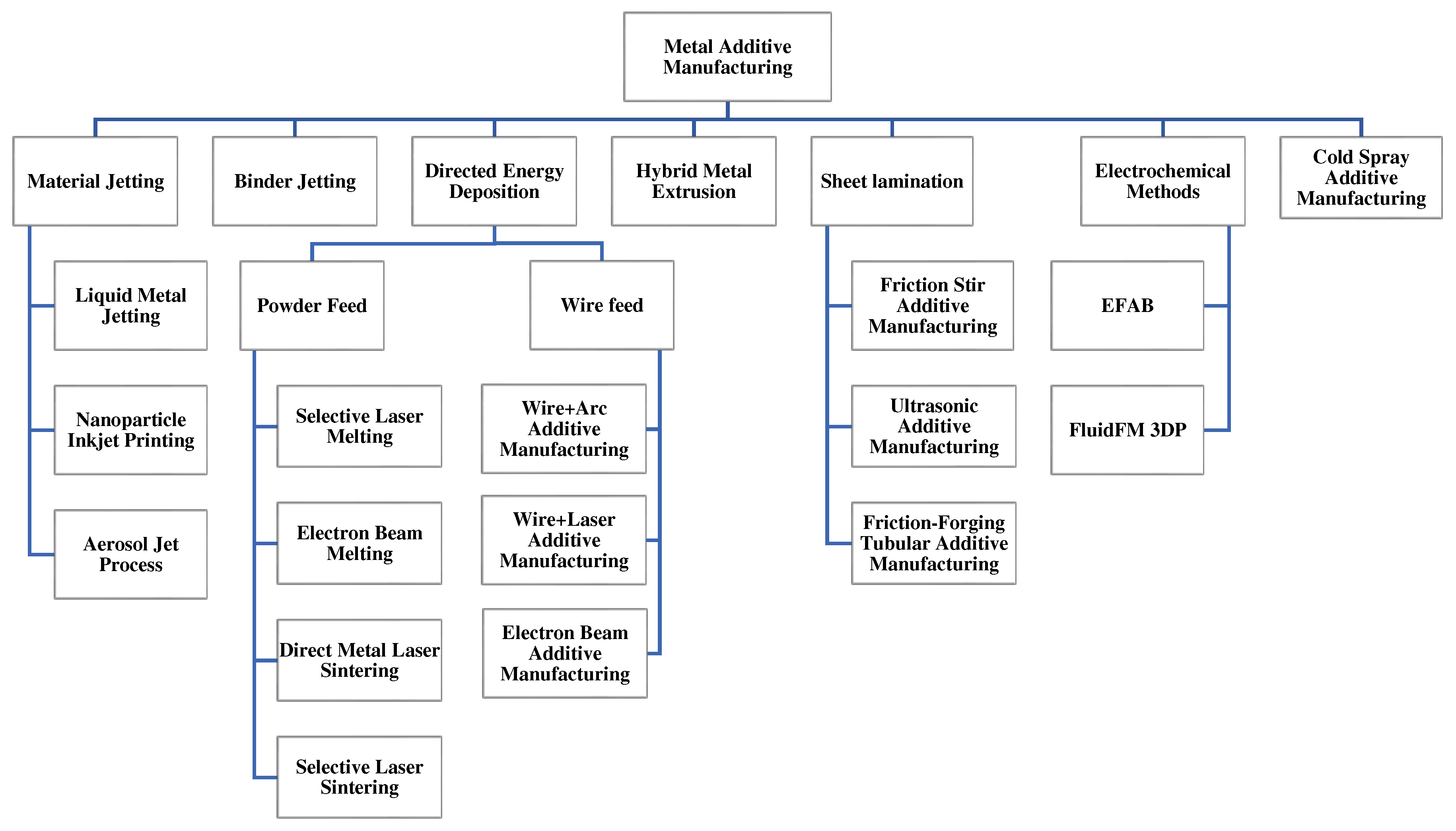
Figure 2.
Continuous and drop-on-demand methods of jetting 3D printing methods [17].
Figure 2.
Continuous and drop-on-demand methods of jetting 3D printing methods [17].
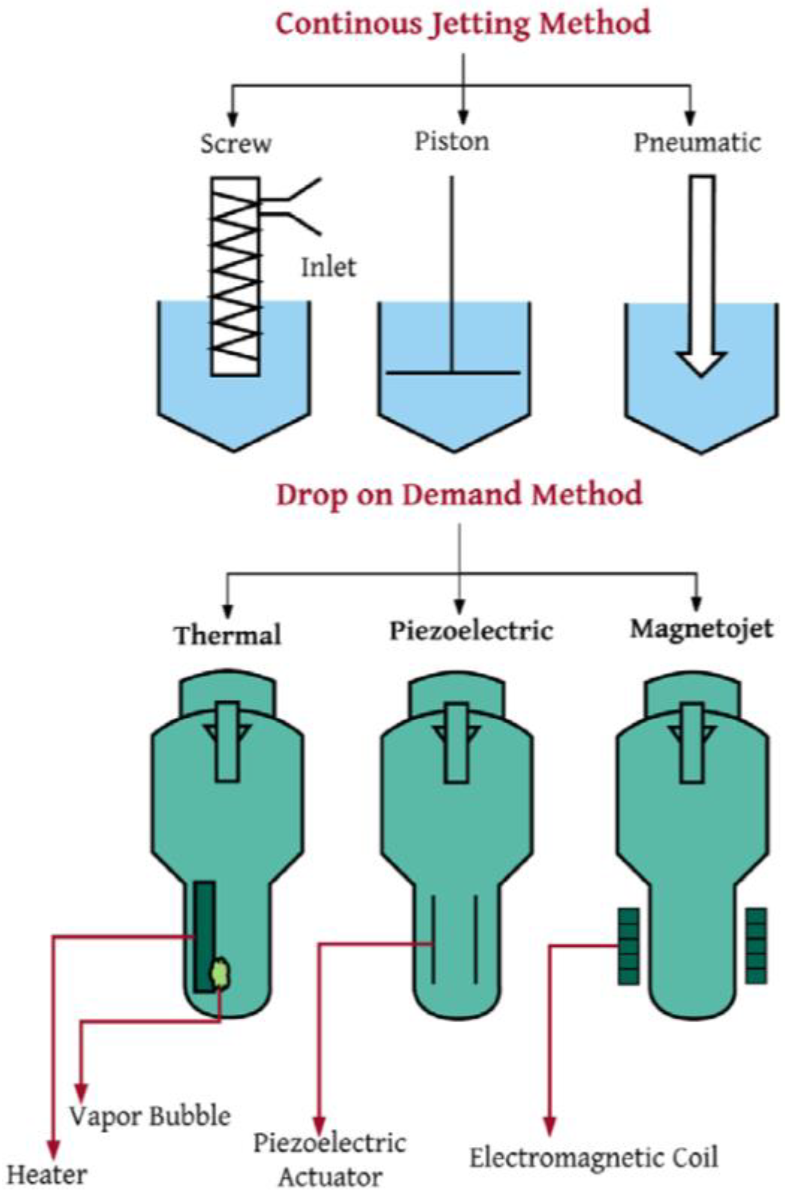
Figure 3.
Schematic of the piezoelectric inkjet system [21].
Figure 3.
Schematic of the piezoelectric inkjet system [21].
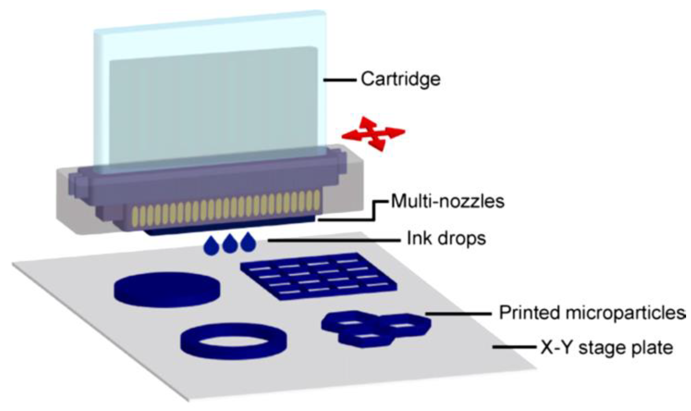
Figure 4.
Schematic of the system of aerosol jet printing [22].
Figure 4.
Schematic of the system of aerosol jet printing [22].
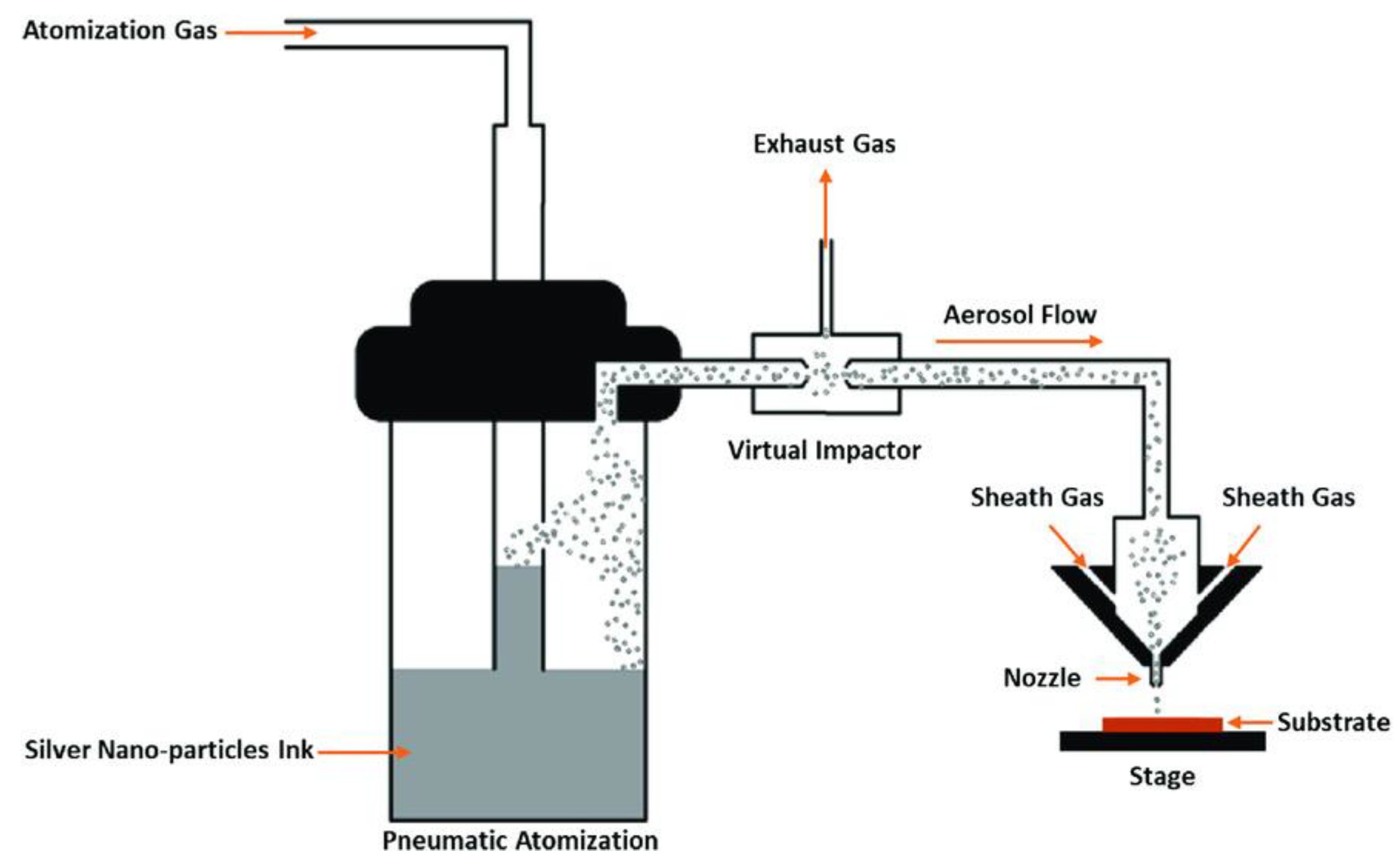
Figure 5.
Schematic of the PBF process [27].
Figure 5.
Schematic of the PBF process [27].
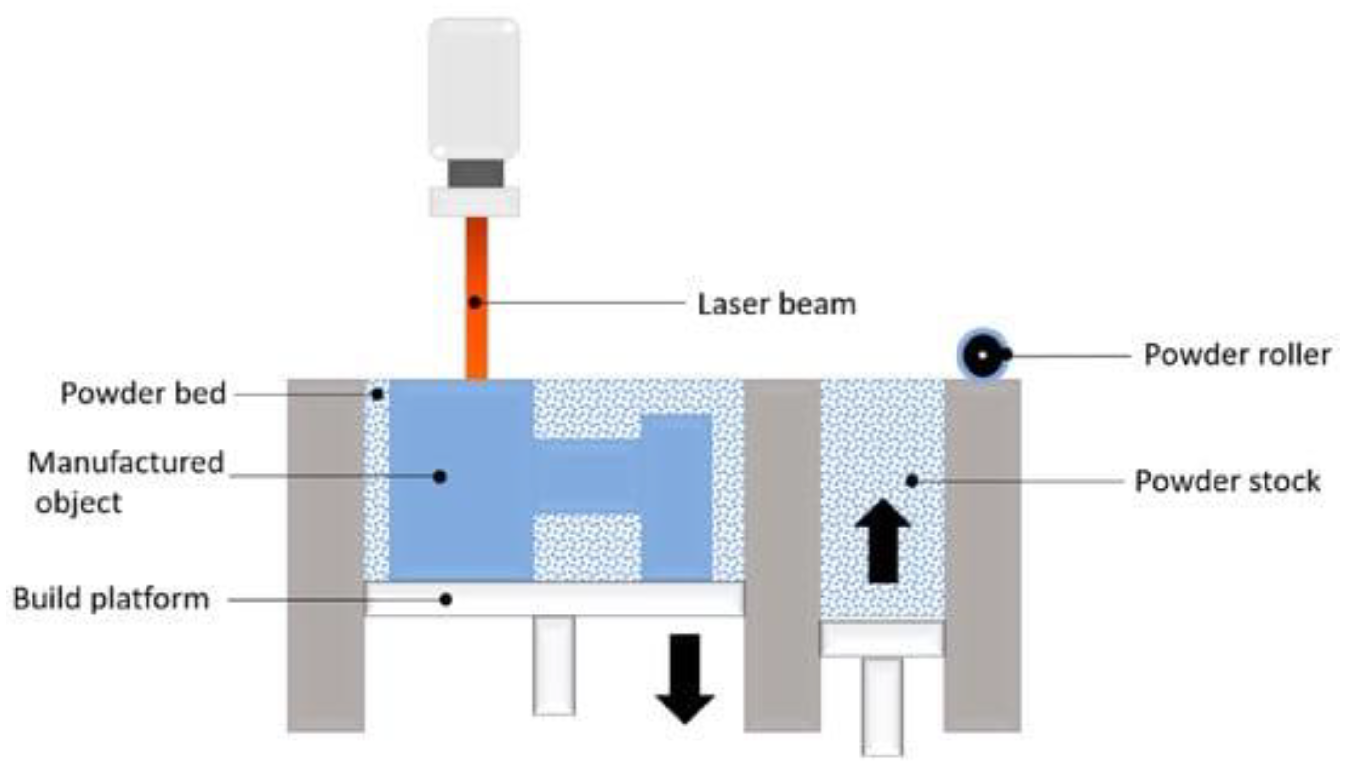
Figure 6.
A schematic of the SLM machine [29].
Figure 6.
A schematic of the SLM machine [29].
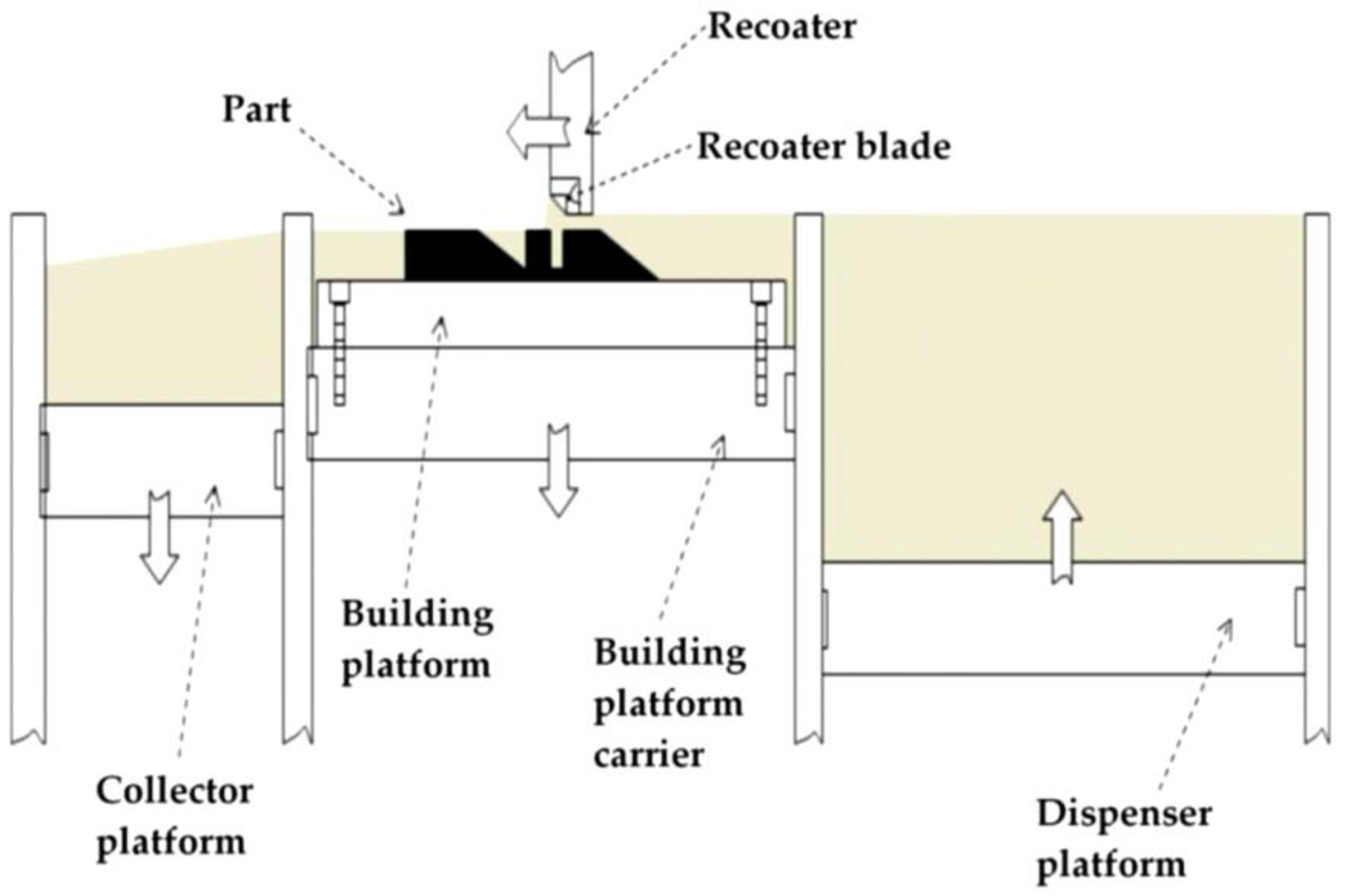
Figure 7.
A schematic of the EBM process [29].
Figure 7.
A schematic of the EBM process [29].
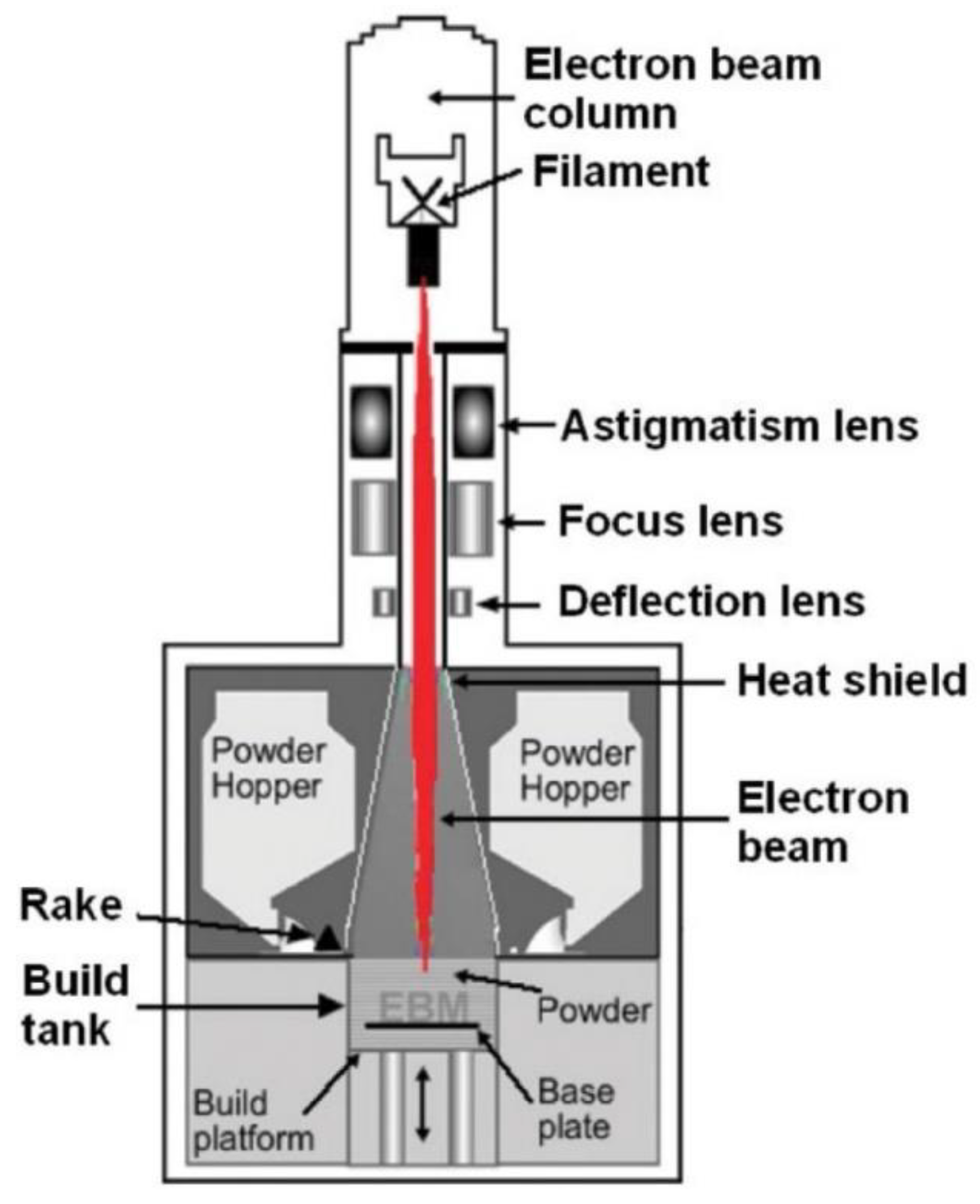
Figure 8.
Schematic diagram of the DMLS process [34].
Figure 8.
Schematic diagram of the DMLS process [34].
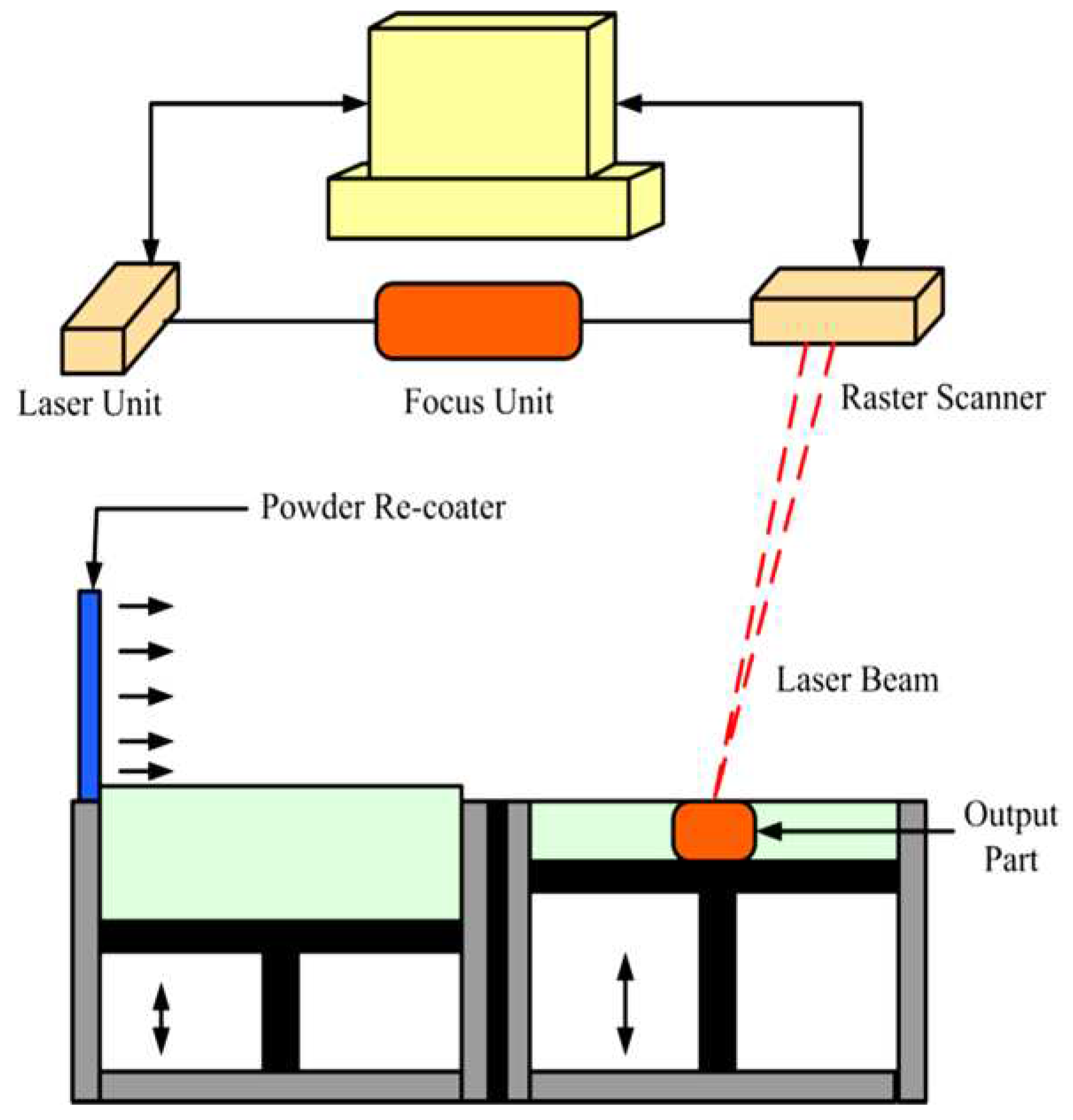
Figure 9.
A schematic of the SLS process [39].
Figure 9.
A schematic of the SLS process [39].
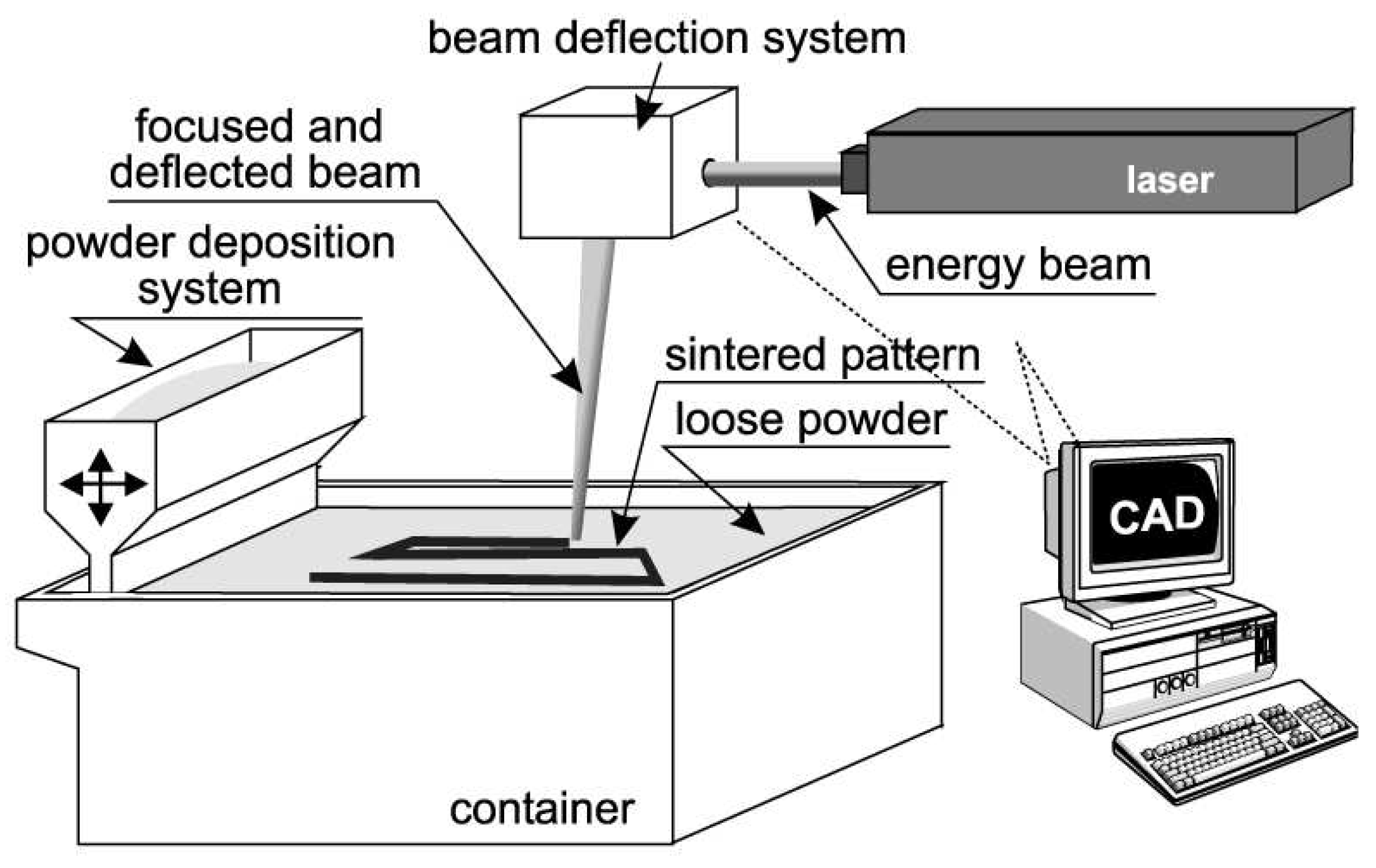
Figure 10.
The schematic of the binder jetting process [42].
Figure 10.
The schematic of the binder jetting process [42].
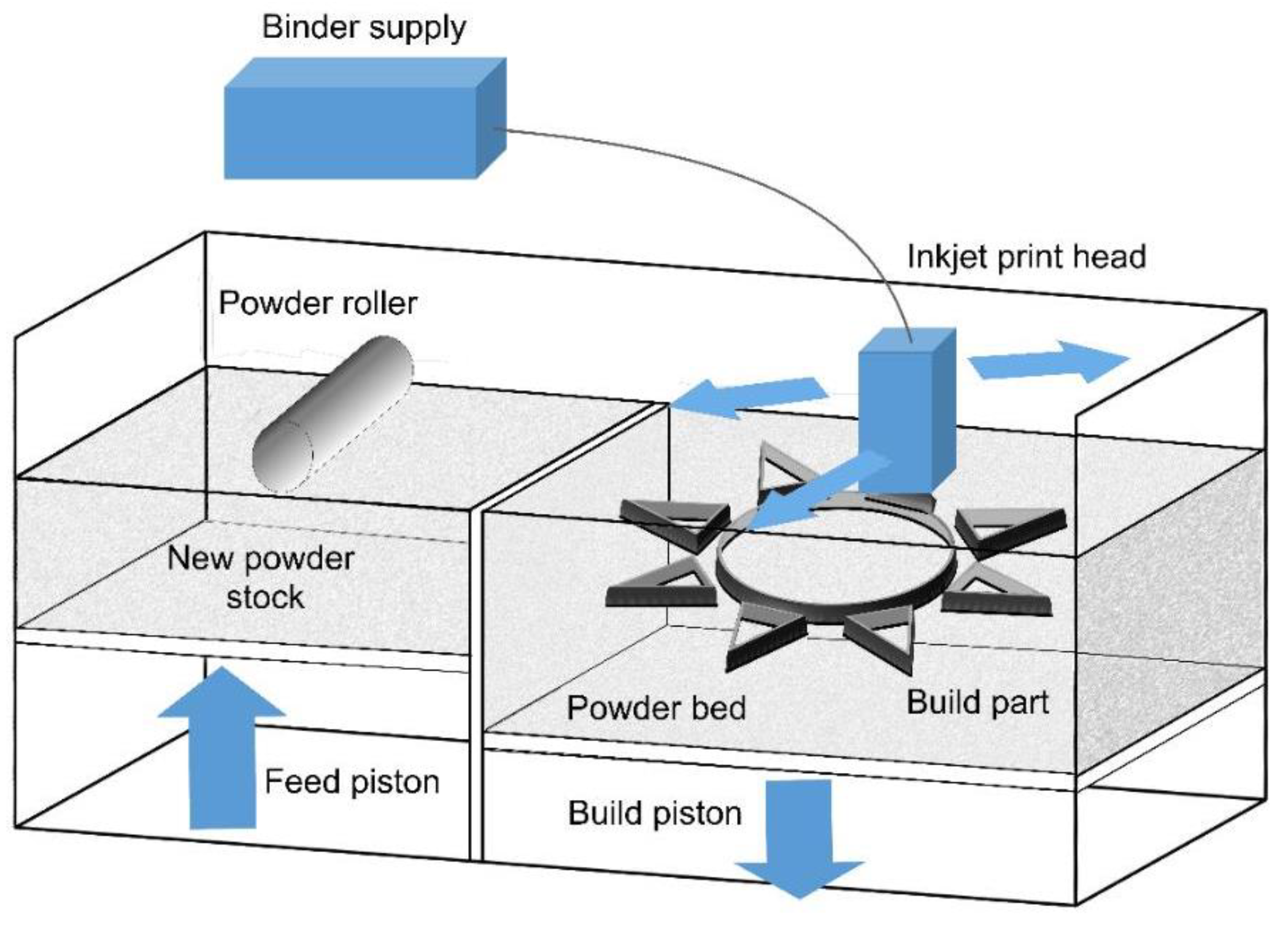
Figure 11.
A schematic of a cold spray gun [45].
Figure 11.
A schematic of a cold spray gun [45].
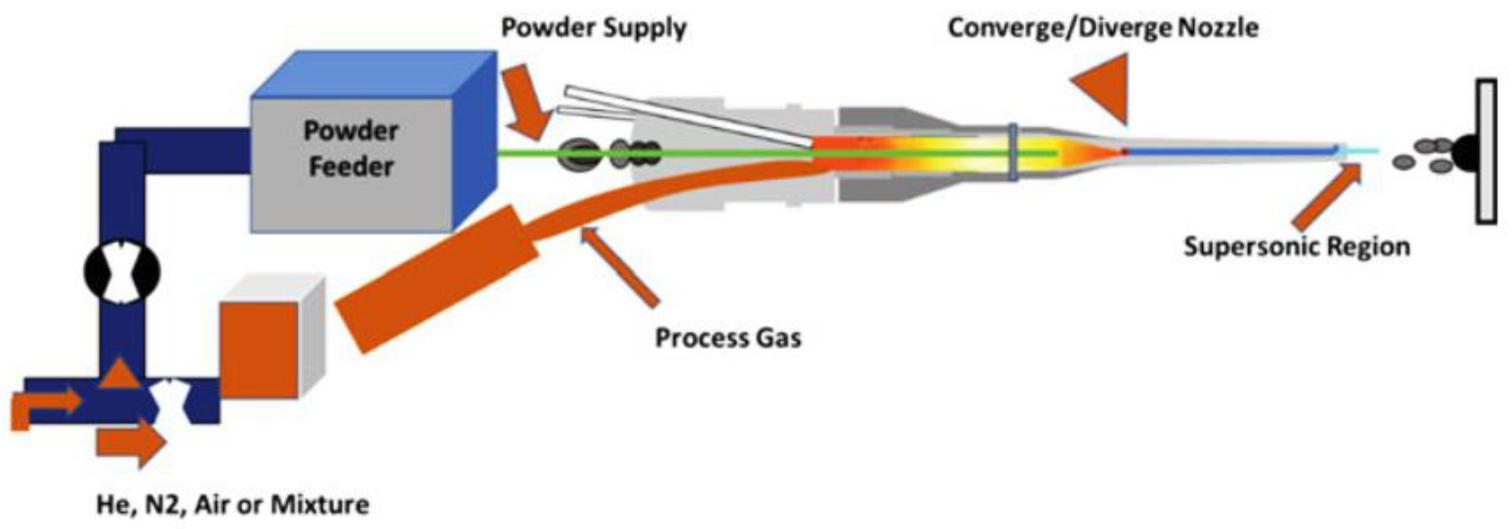
Figure 12.
A schematic of the cold spray components [49].
Figure 12.
A schematic of the cold spray components [49].
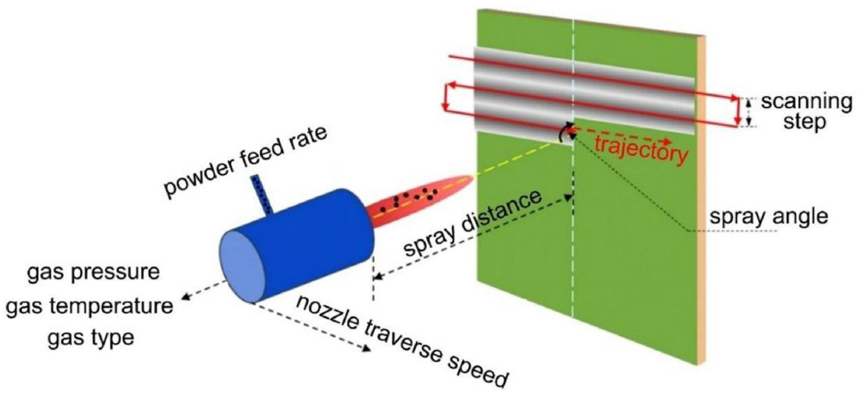
Figure 13.
Schematic of (a) high and (b) low pressure cold spray processes [49].
Figure 13.
Schematic of (a) high and (b) low pressure cold spray processes [49].
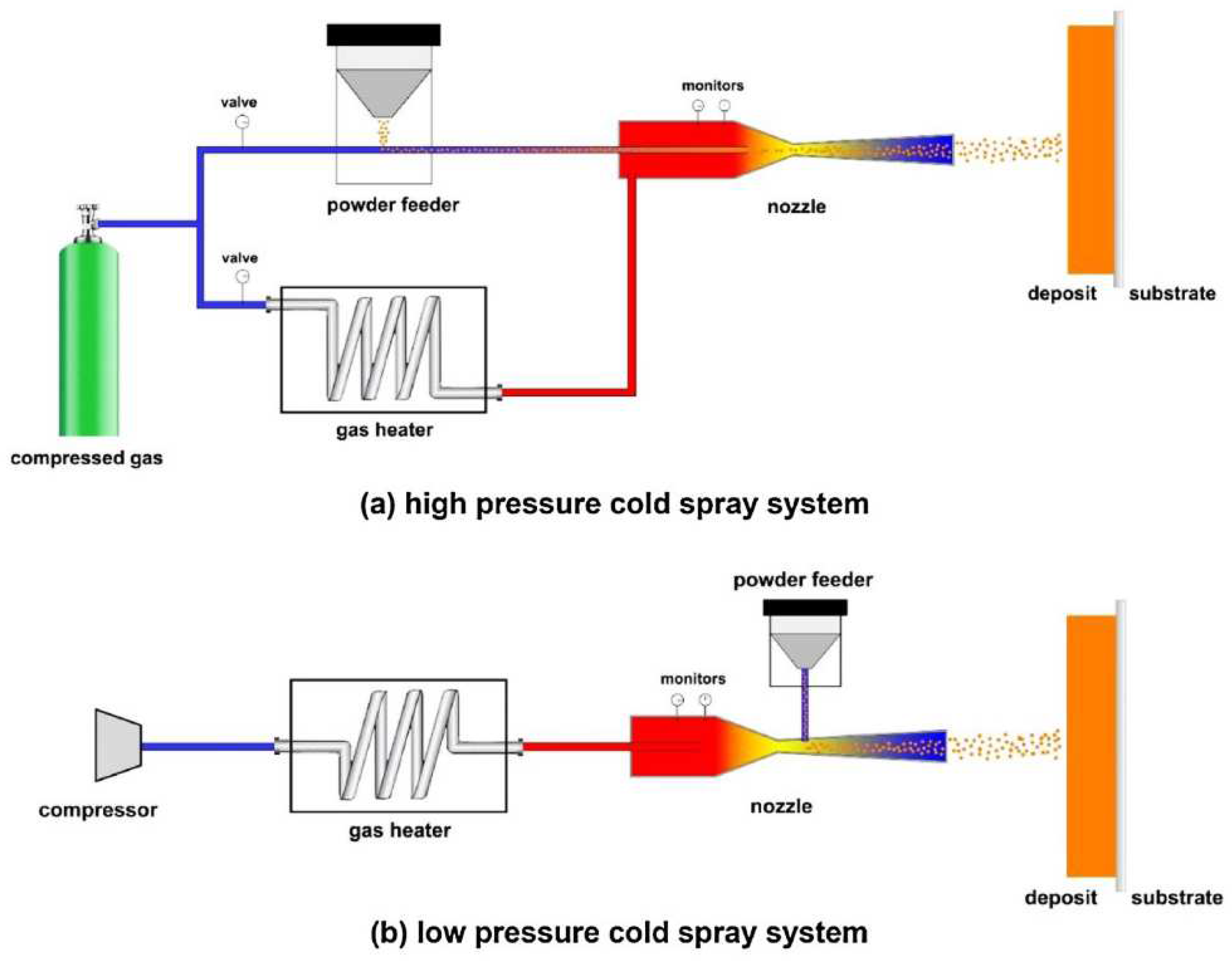
Figure 14.
A schematic of (a) an HYB-AM extruder and (b) an extruder and the deposited structure [51].
Figure 14.
A schematic of (a) an HYB-AM extruder and (b) an extruder and the deposited structure [51].
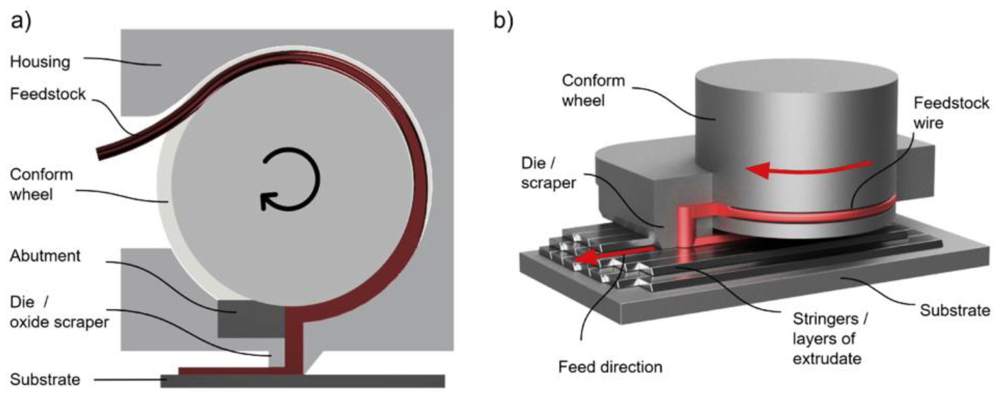
Figure 15.
A schematic of the bonding achieved between the extrudate and the substrate at the pressure exceeding the materials flow stress in the HYB-AM process [51].
Figure 15.
A schematic of the bonding achieved between the extrudate and the substrate at the pressure exceeding the materials flow stress in the HYB-AM process [51].
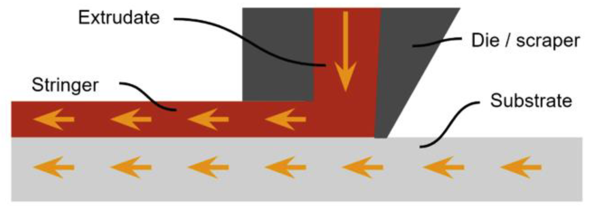
Figure 16.
Schematic of ultrasonic additive manufacturing [56].
Figure 16.
Schematic of ultrasonic additive manufacturing [56].
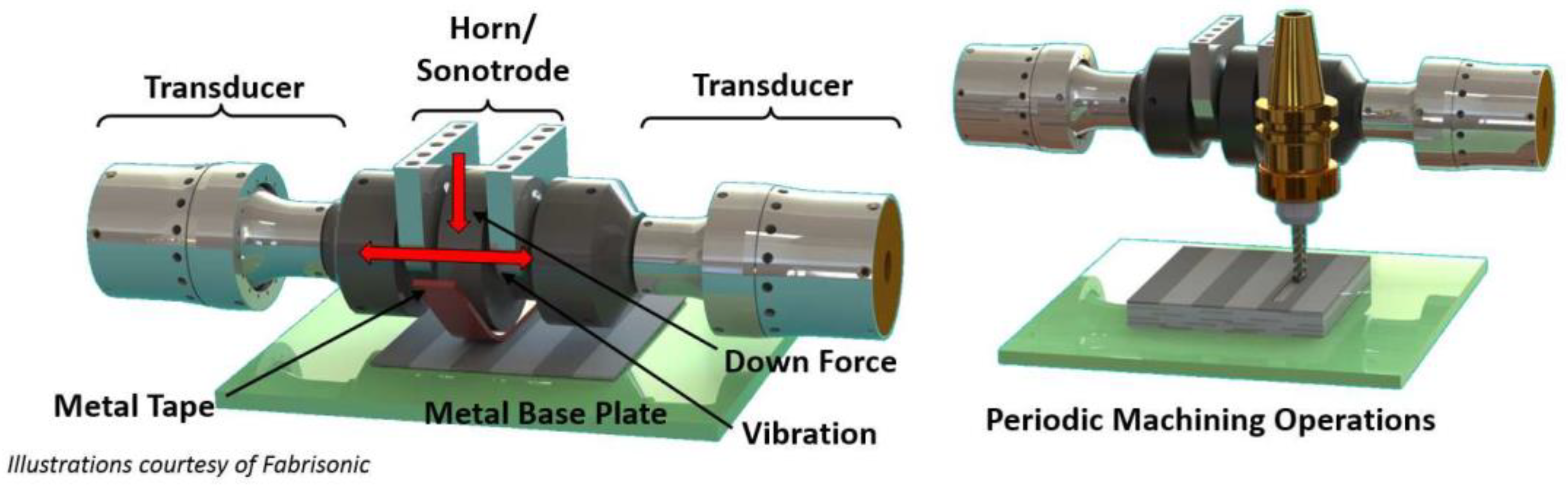
Figure 17.
Schematic arrangement of FSAM [57].
Figure 17.
Schematic arrangement of FSAM [57].
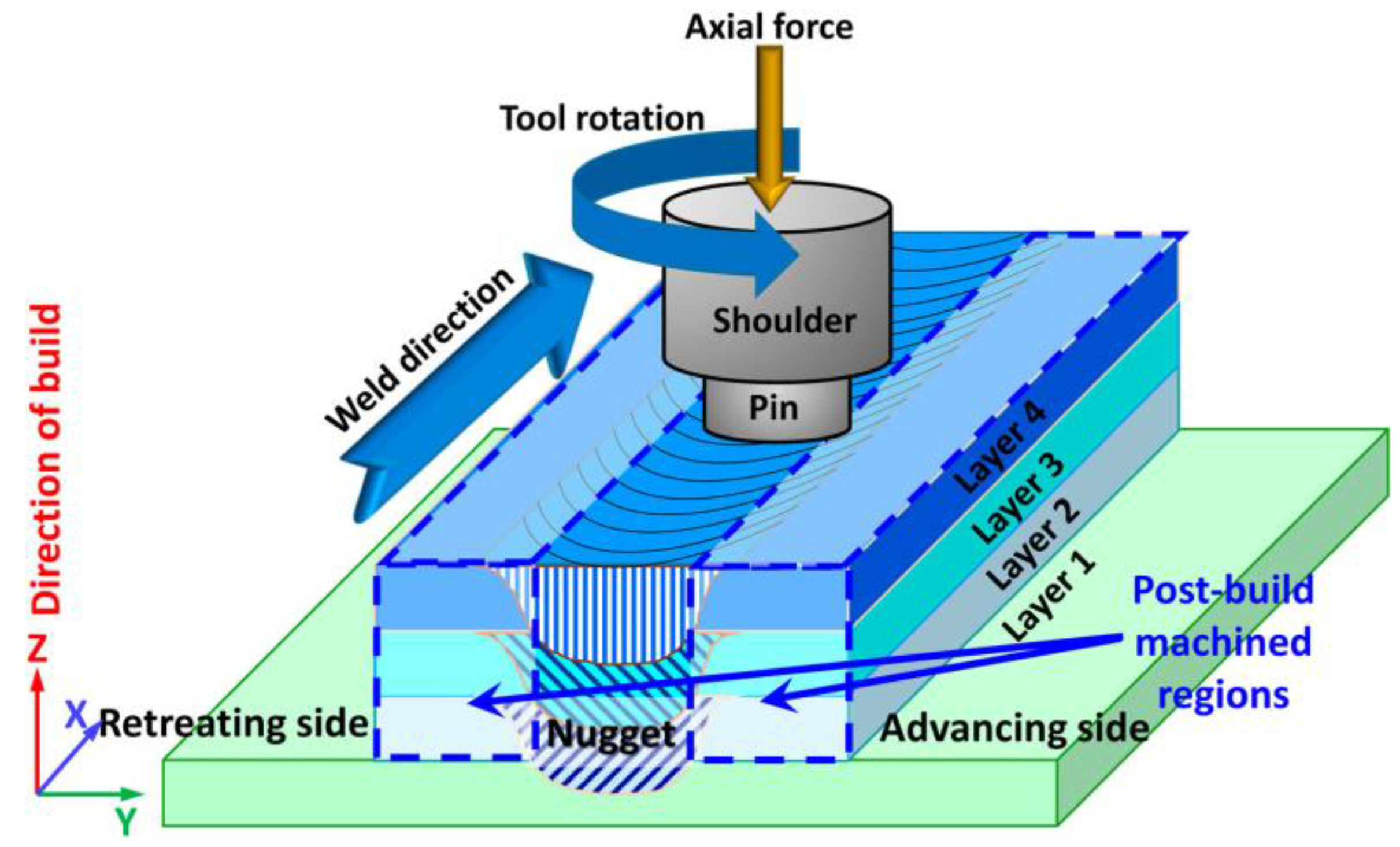
Figure 18.
Steps utilized in FSAM [60].
Figure 18.
Steps utilized in FSAM [60].
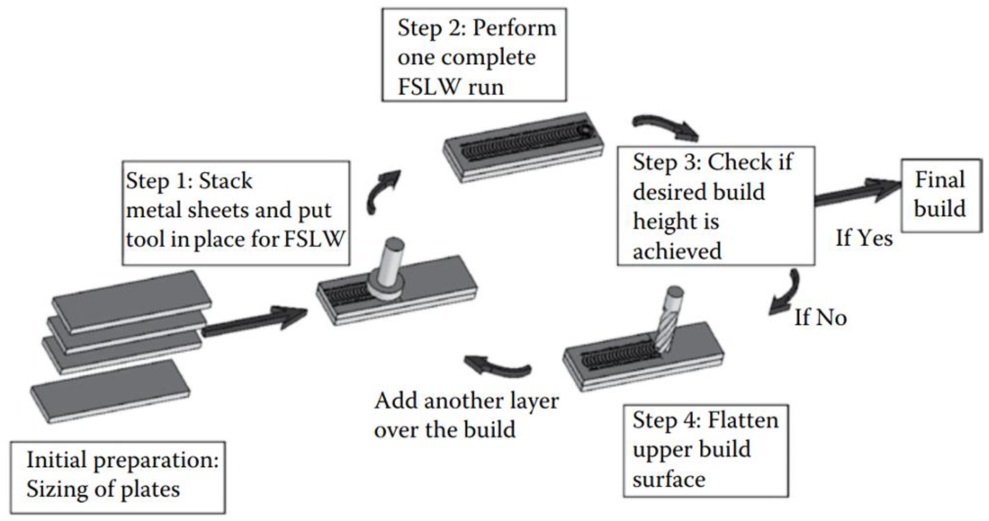
Figure 19.
Different steps of FFTAM process accomplishment: (a) Powder introducing, (b) powder compaction by forging and rotational friction stirring, (c) addition of next powder layer, and (d) new layer consolidation under friction forging [57].
Figure 19.
Different steps of FFTAM process accomplishment: (a) Powder introducing, (b) powder compaction by forging and rotational friction stirring, (c) addition of next powder layer, and (d) new layer consolidation under friction forging [57].
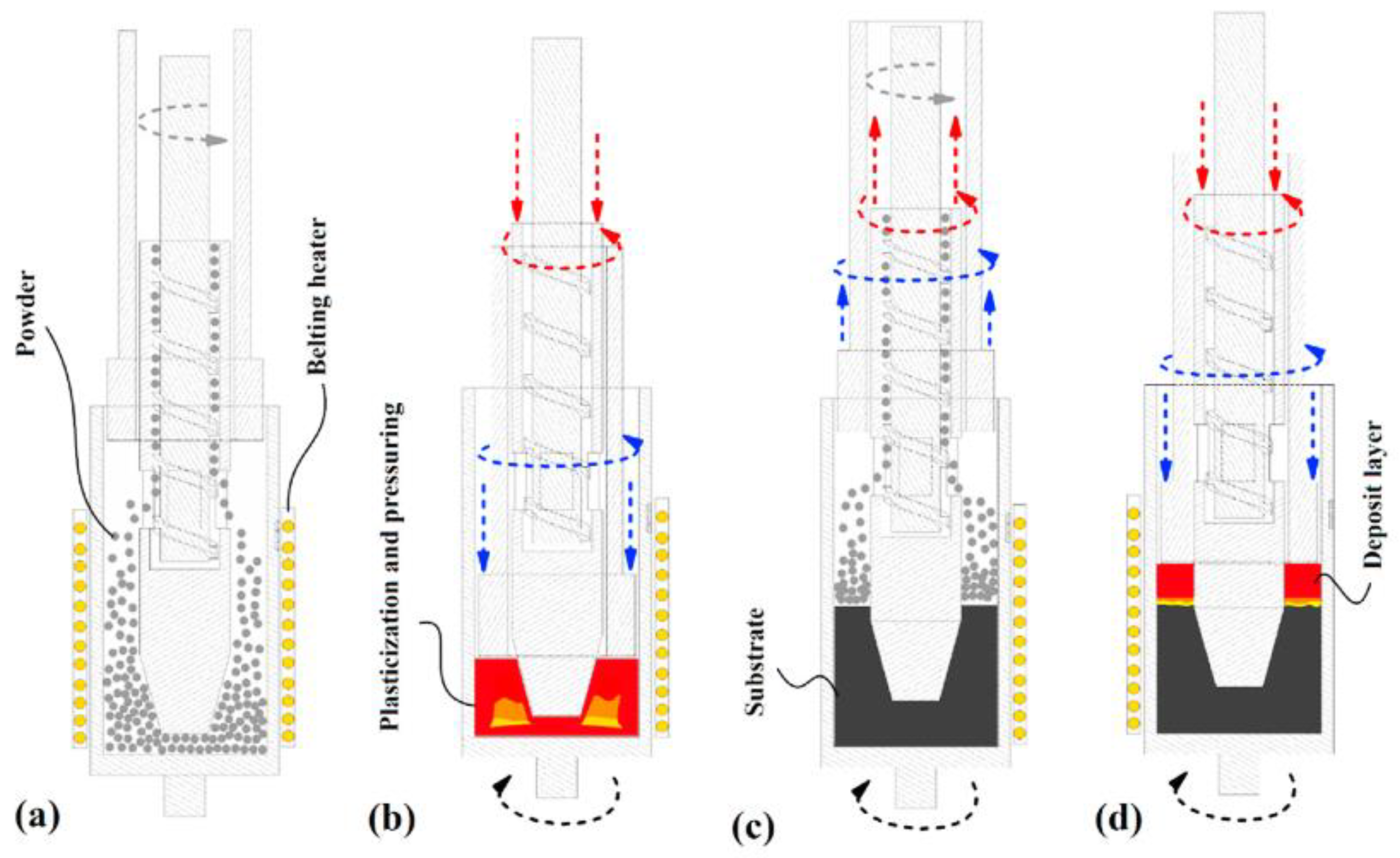
Figure 20.
Classification of directed energy deposition systems [61].
Figure 20.
Classification of directed energy deposition systems [61].
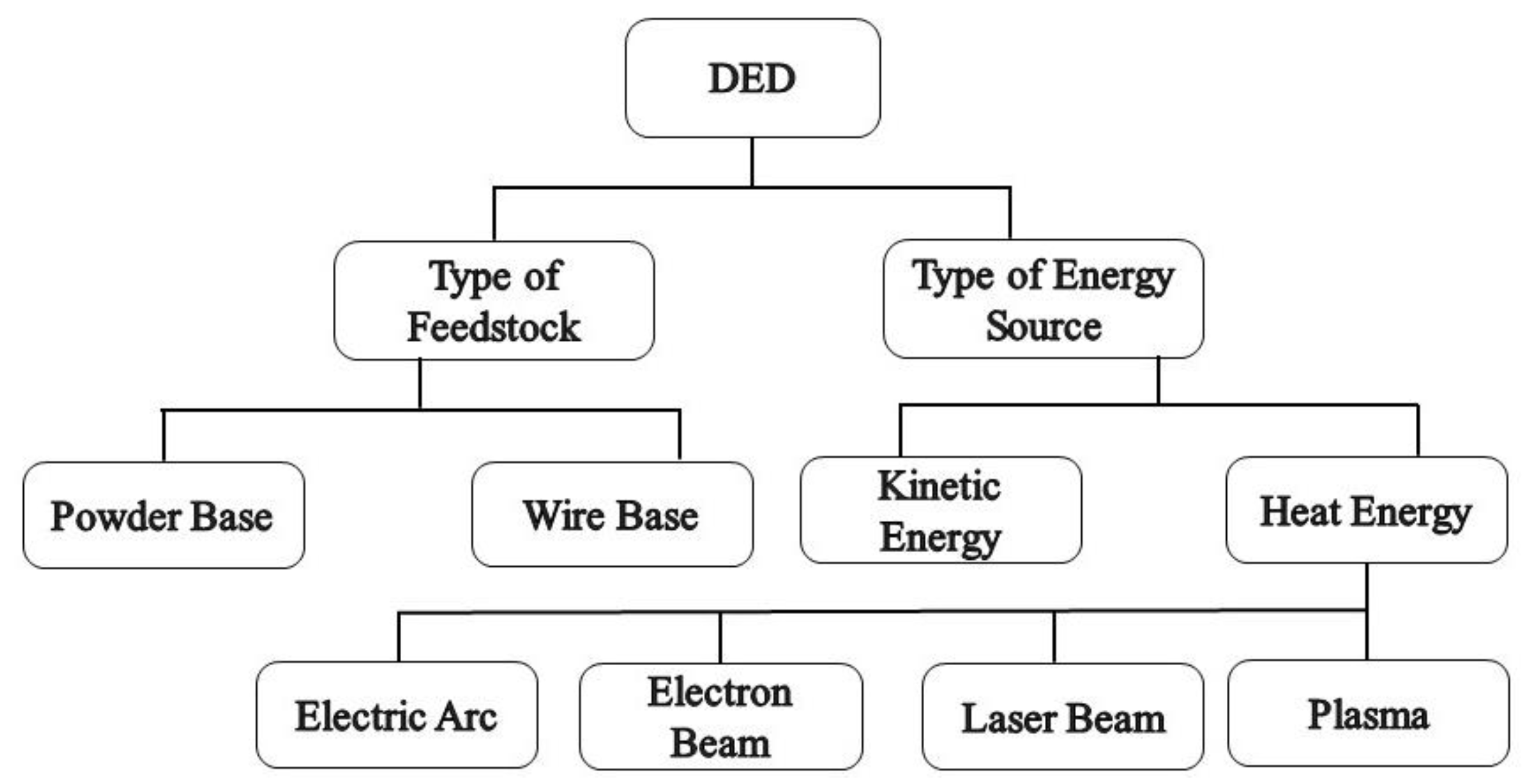
Figure 21.
Schematic of the powder feed system [65].
Figure 21.
Schematic of the powder feed system [65].
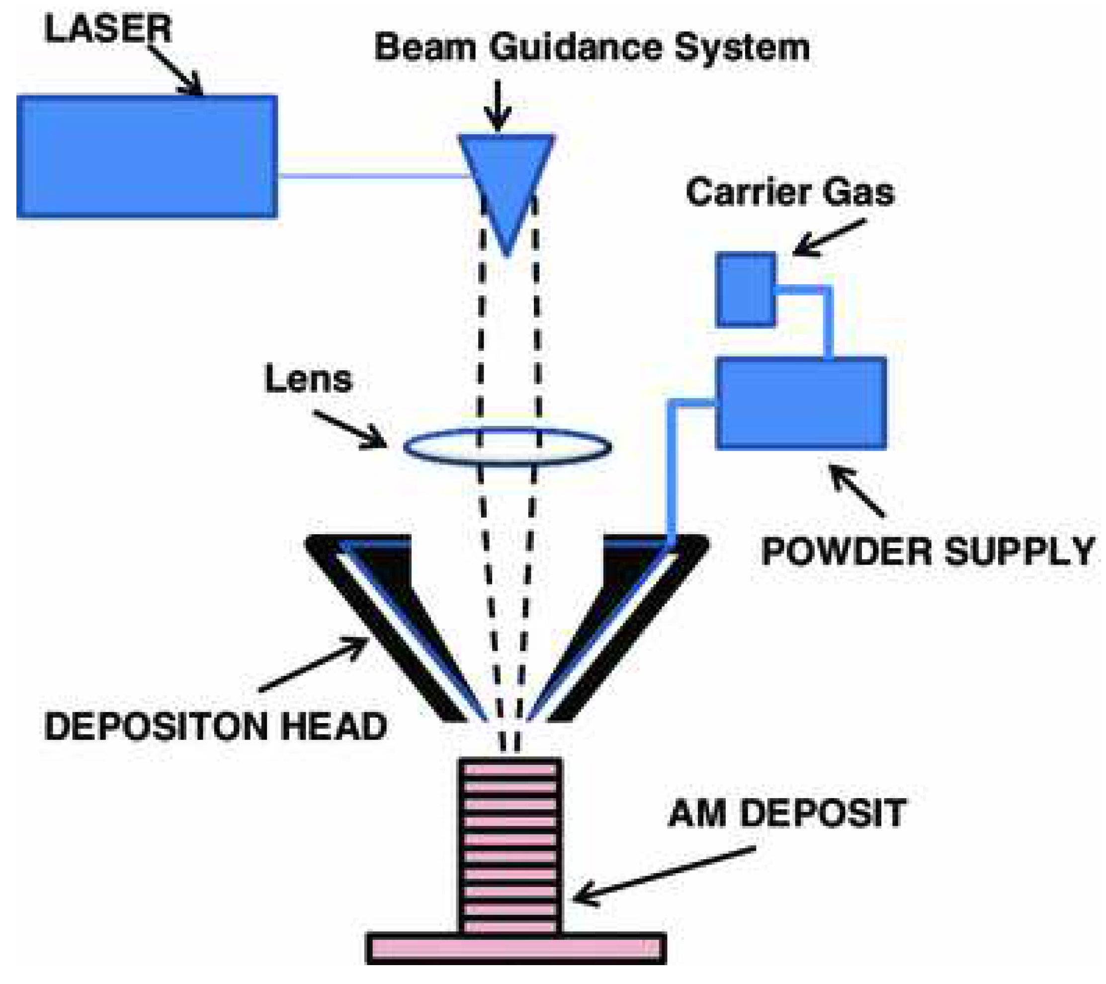
Figure 22.
Basic WAAM process [10].
Figure 22.
Basic WAAM process [10].
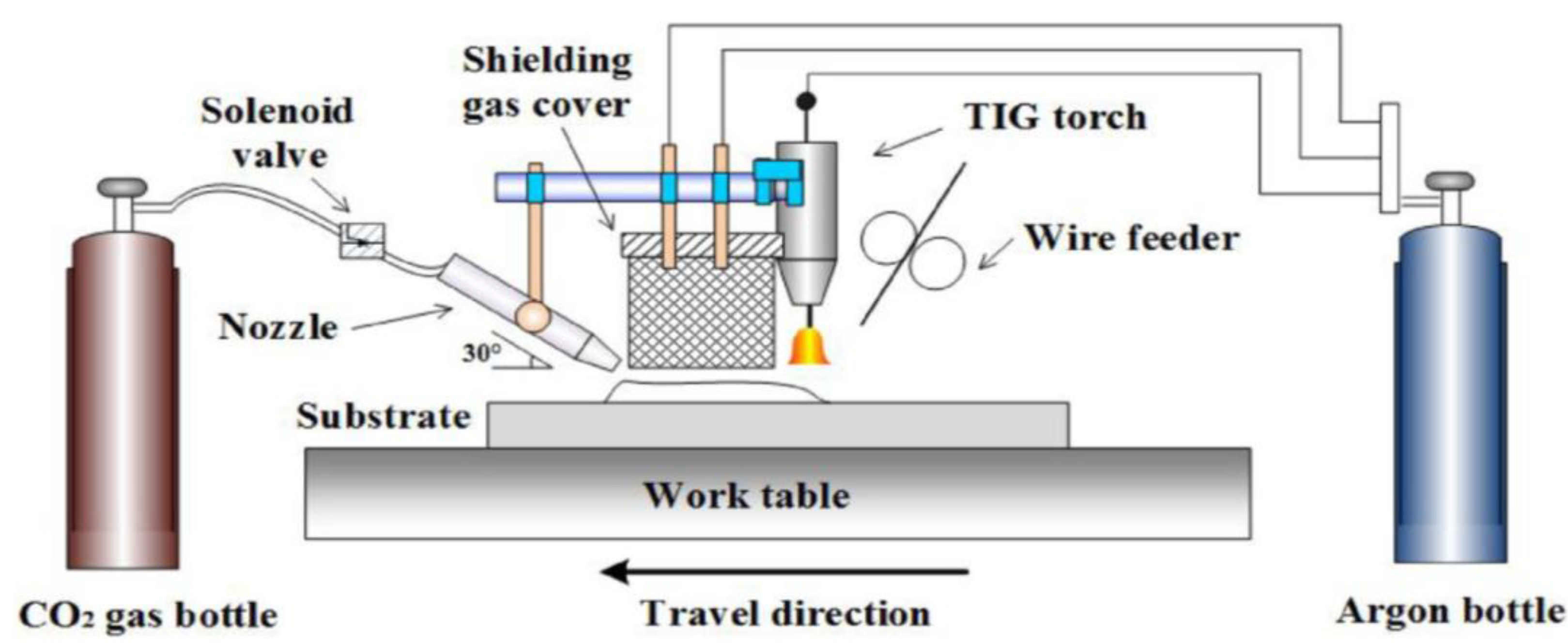
Figure 23.
Schematic drawing of the wire-laser additive manufacturing and top-slide view images of the real process [69].
Figure 23.
Schematic drawing of the wire-laser additive manufacturing and top-slide view images of the real process [69].
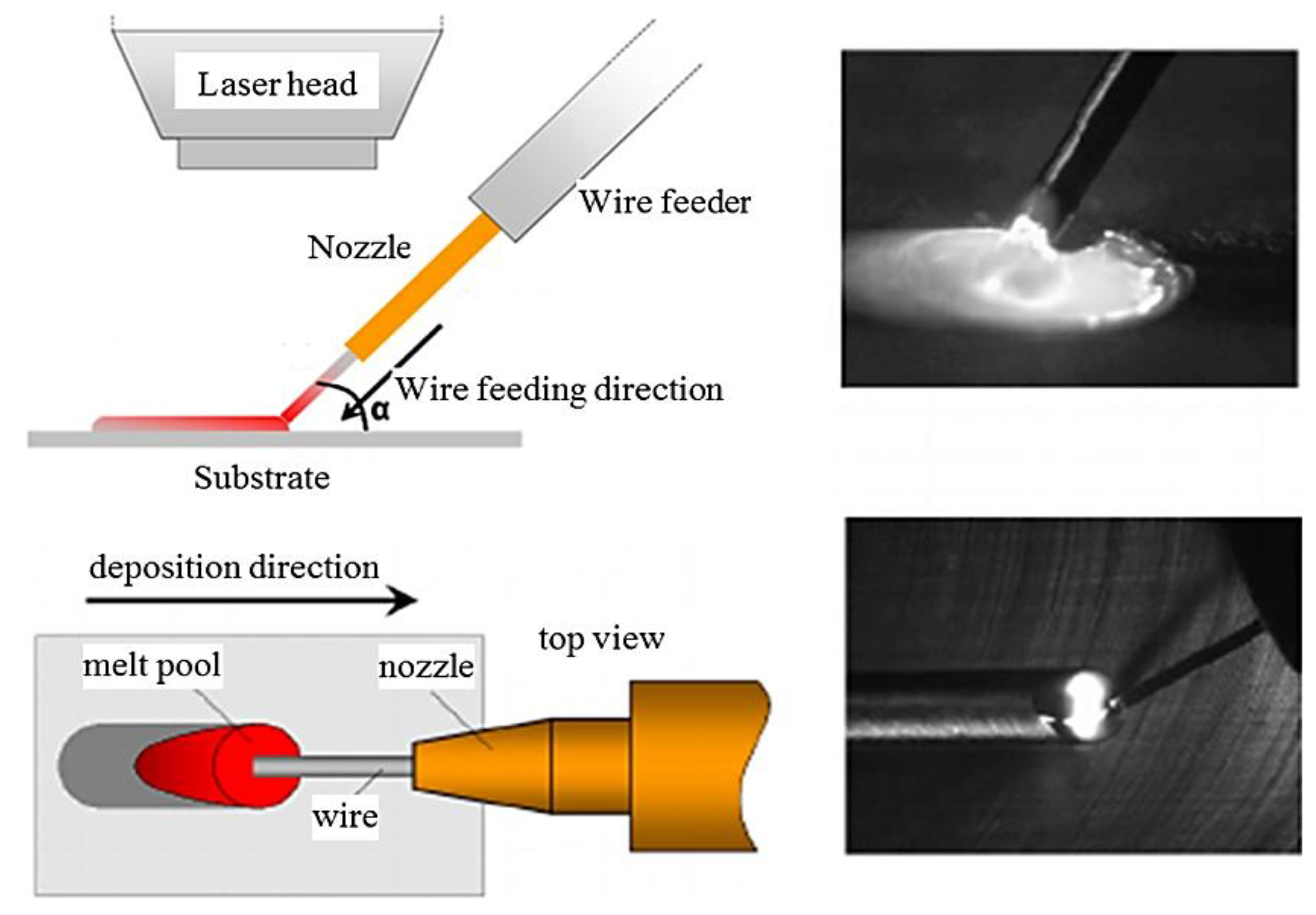
Figure 24.
Basic electron beam additive manufacturing process [74].
Figure 24.
Basic electron beam additive manufacturing process [74].
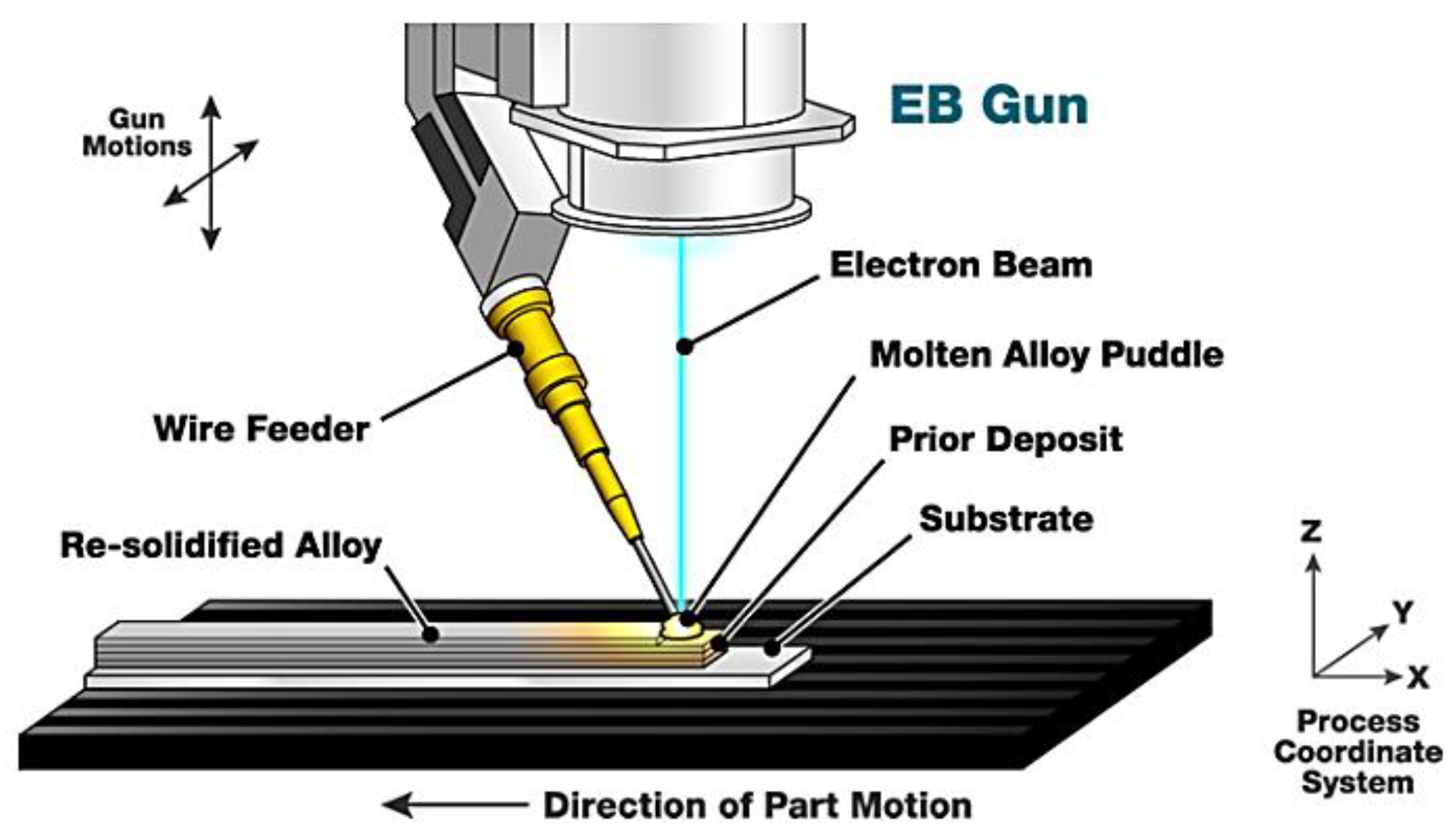
Figure 25.
The EFAB process. A 3-step process is performed on each layer using two materials. Eventually, one material is etched to release the structure [75].
Figure 25.
The EFAB process. A 3-step process is performed on each layer using two materials. Eventually, one material is etched to release the structure [75].
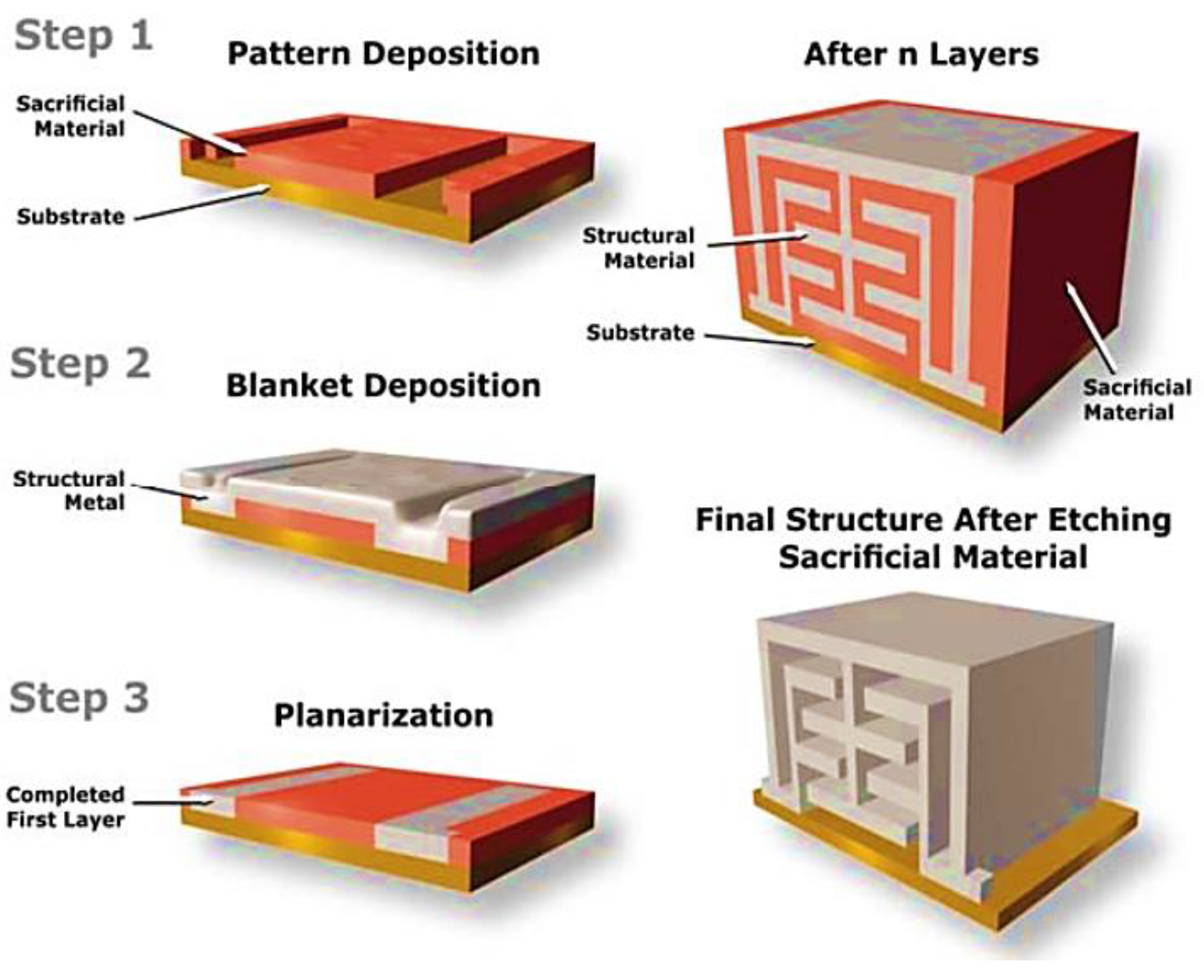
Figure 26.
Fluid FM printing cell. The ion tip dispenses the electrolyte into a buffer bath. At the working electrode, Cu2+ ions are deposited as solid copper [77].
Figure 26.
Fluid FM printing cell. The ion tip dispenses the electrolyte into a buffer bath. At the working electrode, Cu2+ ions are deposited as solid copper [77].
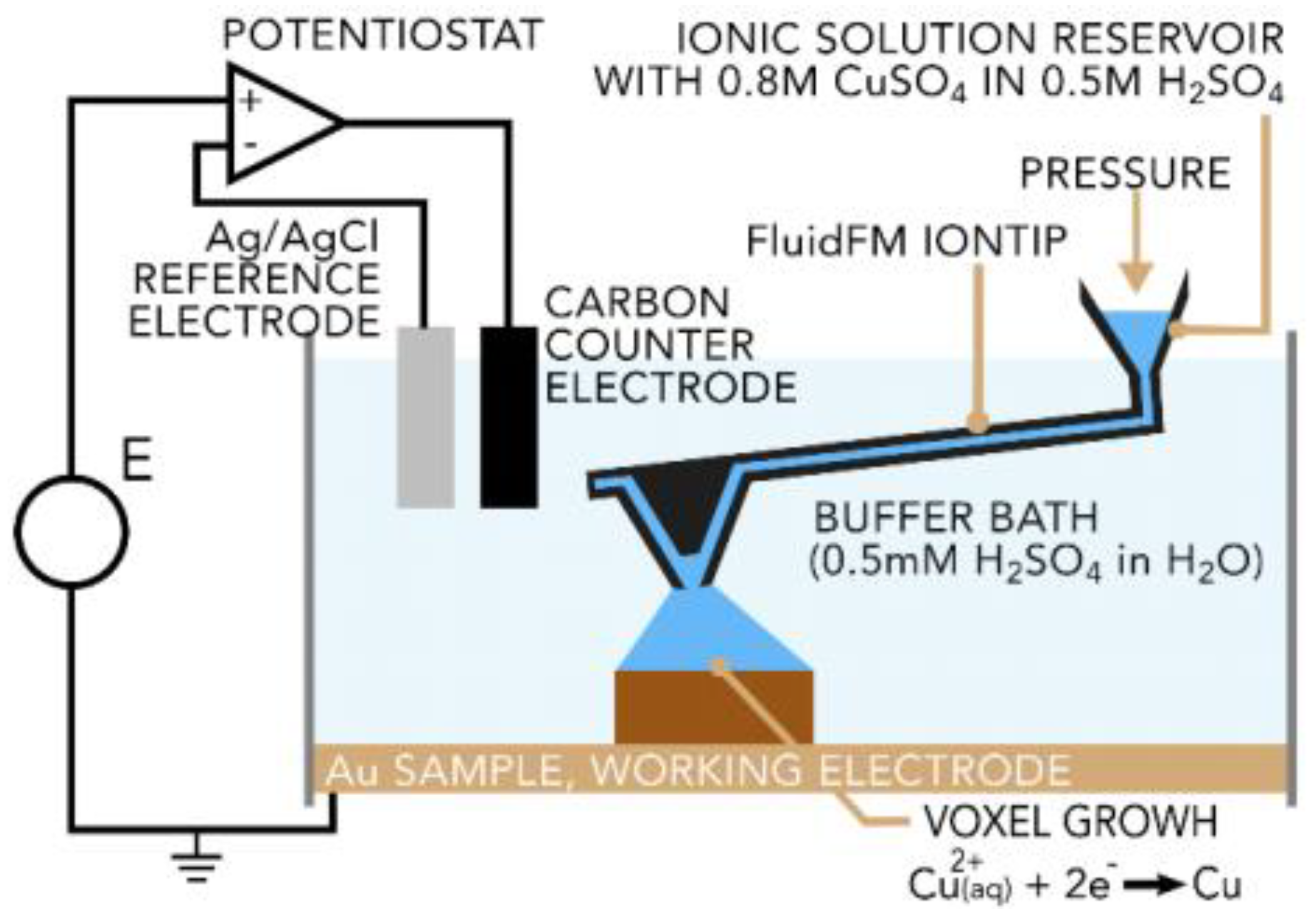

Table 1.
Differences between drop-on-demand (DOD) and continuous methods and their utilizations [16].
Table 1.
Differences between drop-on-demand (DOD) and continuous methods and their utilizations [16].
| Parameters | Drop-on-Demand | Continuous |
|
Jet Speed (droplets per second) |
Less than 10 (kHz) | 10 to 100 (kHz) in a cylindrical configuration and 5 to 20 (kHz) in a pump configuration. |
|
Drop Size Relative to Orifice Size (diameter to diameter) |
Same Which is better for producing smaller drops | Droplet is 1.8 times larger than the orifice diameter, which is better for producing larger drops. |
| Material Usage | Less | Must gutter unwanted droplets. This unused material can be reused in many applications. |
|
Generator (Force/Energy Required) |
More | Less |
Table 2.
Representative powder based DED equipment sources and specifications.
| System | Process | Build volume (mm) | Energy source |
| Optomec (LENS 750) | LENS | 300 × 300 × 300 | 500 W, 1 kW or 2 kW IPG fiber laser |
| Optomec (LENS 850-R) | LENS | 900 × 1500 × 900 | 1 or 2 kW IPG fiber laser |
| POM DMD (66R) | DMD | 3,200°× 3°,670° × 360° | 1-5 kW fiber diode or disk laser |
| Accufusion laser consolidation | LC | 1,000 × 1,000 × 1,000 | Nd:YAG laser |
Disclaimer/Publisher’s Note: The statements, opinions and data contained in all publications are solely those of the individual author(s) and contributor(s) and not of MDPI and/or the editor(s). MDPI and/or the editor(s) disclaim responsibility for any injury to people or property resulting from any ideas, methods, instructions or products referred to in the content. |
© 2023 by the authors. Licensee MDPI, Basel, Switzerland. This article is an open access article distributed under the terms and conditions of the Creative Commons Attribution (CC BY) license (http://creativecommons.org/licenses/by/4.0/).
Copyright: This open access article is published under a Creative Commons CC BY 4.0 license, which permit the free download, distribution, and reuse, provided that the author and preprint are cited in any reuse.


