
Submitted:
01 July 2023
Posted:
04 July 2023
You are already at the latest version
Abstract
Urea, a prevalent component found in wastewater, shows great promise as an alternative substrate to water for energy-efficient hydrogen production by electrolysis. However, the sluggish kinetics of the anodic urea oxidation reaction (UOR) significantly hampers the overall reaction rate. To address this challenge, this article presents a comprehensive study focusing on the controlled fabrication of hierarchically structured nanomaterials as potential catalysts for UOR. The prepared MnO2@NiCo-LDH hybrid catalyst demonstrates remarkable improvements in reaction kinetics, benefiting from synergistic enhancements in charge transfer and efficient mass transport facilitated by its unique three-dimensional architecture. Notably, the catalyst exhibits an exceptionally low onset potential of 1.228 V and requires only 1.326 V to achieve an impressive current density of 100 mA cm-2, representing a state-of-the-art performance in UOR. These findings highlight the tremendous potential of this innovative material-designing strategy to drive advancements in electrocatalytic processes.
Keywords:
urea oxidization
; hierarchical nanostructure
; nickel cobalt hydroxide
1. Introduction
As a promising and environmentally-friendly energy carrier, hydrogen (H2) has garnered significant attention as a potential substitute for fossil fuels in future energy systems [1,2]. The electrochemical water splitting reaction (2H2O → 2H2 + O2) provides an eco-friendly and sustainable pathway for hydrogen production, enabling the efficient conversion of surplus or low-quality electricity into chemical energy stored in the form of hydrogen gas [3,4,5,6]. Regrettably, the efficiency of the water-splitting process is significantly impeded by the high theoretical reaction potential of 1.23 V and the sluggish kinetics of the oxygen evolution reaction (OER) occurring at the anode side [7]. In order to address this limitation, several novel reaction schemes have been proposed as alternatives to the OER. The urea oxidation reaction (UOR), with a favourable thermodynamic potential of only 0.37 V, has therefore attracted considerable research interest [8]. Urea, which naturally occurs in abundance in human urine, serves as an abundant resource for this reaction. Despite its great promise, the UOR still encounters significant kinetic barriers that hinder its efficiency [9,10]. Therefore, the development of active catalysts is imperative to overcome these challenges. Numerous transition metal-based compounds have been extensively investigated as potential catalysts for the UOR [10,11,12,13,14,15,16,17,18]. Among the various catalysts investigated for UOR, Ni-Co binary hydroxides stand out as particularly attractive options due to their abundant availability in nature and remarkable catalytic performance [17,19,20]. Despite advancements, there is still considerable scope for enhancing performance to meet the demands of practical applications, necessitating the implementation of innovative material-design strategies.
In this article, we present the design and fabrication of hierarchically structured MnO2@NiCo-LDH nanosheet arrays supported on nickel foam (NF) and their applications as an efficient UOR electrocatalyst. Ultrathin MnO2 nanosheet arrays were first formed on NF via hydrothermal growth, which serves as a conductive substrate for the electrodeposition of (Ni,Co)-based layered double hydroxide (NiCo-LDH) nanosheet. The NiCo-LDH loading density was readily controlled by tuning the deposition current density and time. Remarkably, the hierarchical MnO2@NiCo-LDH exhibited dramatically enhanced catalytic performance for UOR, showing an onset potential of only ~1.228 V and over doubly increased current densities over a wide potential range.
2. Materials and Methods
2.1. Preparation of MnO2@NiCo-LDH Nanosheet Arrays
Commercial nickel foam (NF), with a thickness of 1 mm, was cut into pieces measuring 1 cm × 3 cm for subsequent use. These nickel foam pieces underwent an initial treatment in a 1 M hydrochloric acid solution to remove the naturally formed oxide layer at the surface.
Ultrathin MnO2 nanosheet arrays were grown on the surface of the cleaned NF via hydrothermal synthesis by adopting our previously reported method. For the preparation of MnO2@NiCo-LDH, electrodeposition was carried out in a three-electrode system. The MnO2-coated nickel foam acted as the working electrode, a piece of platinum (Pt) foil served as the counter electrode, and a saturated calomel electrode (SCE) was utilized as the reference electrode. An aqueous solution containing 0.1 M Ni(NO3)2·6H2O and 0.1 M Co(NO3)2·6H2O served as the electrolyte. By adjusting the electrodeposition current density, samples with varying NiCo-LDH loading ratios were obtained.
2.2. Characterizations
Scanning electron microscopy (SEM) and transmission electron microscopy (TEM) investigations were conducted on the FEI APREO-S field emission scanning electron microscope and the JEOL JEM-F200 scanning transmission electron microscope, respectively. X-ray photoelectron spectroscopy (XPS) data were acquired using a Thermo Fisher Scientific ESCALAB X-ray photoelectron spectrometer, with all the spectra calibrated to align the C 1s peak at 284.8 eV. X-ray diffraction (XRD) patterns were collected on a RIGAKU Miniflex X-ray diffractometer, with Cu–Kα radiation, at a scan rate of 5° per minute.
2.3. Electrochemical Measurements
The OER tests were conducted in a standard 1 M KOH (pH = 13.6) solution, with the addition of 0.5 M urea in the alkaline solution for the UOR tests. To record the linear sweep voltammetry (LSV) curves, a scan rate of 5 mV/s was employed, and iR-correction was applied using the current interrupt (CI) method. Electrochemical impedance spectroscopy (EIS) measurements were performed in the potential static mode, with frequencies ranging from 1 to 105 Hz and an oscillation amplitude of 10 mV at an overpotential of 450 mV vs. Hg/HgO (balanced with 1 M KOH). To account for pH effects, potentials were converted to the reversible hydrogen electrode (RHE) scale using the Nernst equation (E vs. RHE = E vs. ref + 0.059 * pH + 0.114 V). The potential of the Hg/HgO electrode was also calibrated against a Pt|H2 (g) electrode in the 1 M KOH electrolyte by using a multimeter [21], showing a potential of 0.916 V (Figure S1), which is consistent with the above calculation.
3. Results and Discussion
3.1. Fabrication and Electrocatalytic Performance of MnO2/NF
Ultrathin MnO2 nanosheet arrays supported on NF were utilized as a substrate for the deposition of NiCo-LDH. These MnO2 nanosheet arrays were selected because of their easy synthesis, large accessible surface areas, as well as half-metallic electronic properties. SEM images (Figure S2) confirm the formation of vertically aligned MnO2 nanosheets on the surface of NF, which is consistent with our previous report [21]. The bare NF and NF-supported MnO2 nanosheet arrays were employed as substrates for the electrodeposition of the NiCo-LDH active layer from solutions containing nickel and cobalt nitrate salts. As depicted in Equations (1) and (2), the deposition was triggered through the increase of local pH at the surface of the electrode as a result of the electrochemical reduction of nitrate ions.
The formation of NiCo-LDH over the MnO2 was investigated using SEM. As shown in Figure 1, when the deposition was carried out at the current density of -20 mA cm-2 and kept for a short time of 50 s, a uniform coating of LDH nanosheets was observed on the surfaces of individual MnO2 nanosheets. Importantly, there were still ample free spaces present among the MnO2@NiCo-LDH hybrid nanosheets. However, as the deposition time increased, a continuous overcoating of LDH occurred. For example, after deposition for 150 s, nearly all the available spaces between the primary MnO2 nanosheets were occupied with LDH, and concurrently, cracks started to form within the overall deposition layer. These cracks became more pronounced as the deposition time was further extended to 200 s. As a control, NiCo-LDH was also deposited on bare NF, and the SEM image reveals that the LDH nanosheets were organized into close-packed microspheres (Figure S3).
With a hierarchical structure, the MnO2@NiCo-LDH fabricated with a deposition time of 50 s was further investigated in TEM. The presence of vertically aligned NiCo-LDH over the MnO2 sheets was clearly demonstrated by the emergence of conspicuous black strips observed atop the bulk nanosheets in the TEM image (Figure 2a). Upon further analysis using high-resolution transmission electron microscopy (HRTEM), distinct lattice fringes with a measured spacing of 0.46 nm (Figure 2b) were observed. These fringes are indicative of the interlayer spacing of the (001) atomic planes of the hydroxide, as documented in the hydroxide's crystallographic database entry (PDF#73-1520). Notably, the selected area electron diffraction (SAED) pattern (Figure 2c) exhibited exclusive diffraction rings that matched the δ-MnO2 phase (PDF#80-1098), suggesting the low crystallinity of the hydroxide deposits. Moreover, the high-angle annular dark-field (HAADF) and energy-dispersive X-ray spectroscopy (EDS) mapping images (Figure 2d–g) provided compelling evidence of the homogeneous distribution of the Mn, Ni, and Co elements throughout the sample. The general atomic contents of these elements were determined to be 16.41 % (Mn), 7.13% (Ni), and 4.81% (Co) according to the EDS spectrum (Figure S4).
The performance of MnO2@NiCo-LDH for urea oxidation reaction (UOR) was assessed in a 1 M KOH solution containing 0.5 M urea. NiCo-LDH/NF, MnO2/NF, and bare NF were used as reference catalysts. The LSV curves and potential statistics required to achieve specified current densities are presented in Figure 3a,b, respectively. It is evident that the MnO2@NiCo-LDH possesses a significantly improved performance for UOR compared to the reference catalysts. Notably, by enlarging the low current density region of the LSV curves (Figure S5), the onset potential of MnO2@NiCo-LDH was measured as 1.228 V vs. RHE. This value is below both the thermodynamic redox potential of the OER (1.230 V) and the onset potentials of NiCo-LDH/NF (1.267 V), MnO2/NF (1.311 V), and bare NF (1.377 V). Significantly, when subjected to an applied potential of 1.5 V vs. RHE, the current density of MnO2@NiCo-LDH impressively reaches 905 mA cm-2. This value surpasses the current densities of NiCo-LDH/NF (398 mA cm-2) and MnO2/NF (337 mA cm-2) by more than two-fold. Similarly, to achieve current densities of 10 and 100 mA cm-2, the MnO2@NiCo-LDH requires potentials of 1.261 and 1.326 V vs. RHE, respectively. These values represent a considerable reduction compared to the potentials required by the reference catalysts. Furthermore, they are on par with the most superior UOR catalysts reported in the literature [20] (Table S1), underscoring the exceptional electrochemical capability of MnO2@NiCo-LDH. In addition, Tafel plots (Figure 3c) were generated based on the LSV curves for analyzing the kinetics of the UOR on the different catalysts. MnO2/NF displayed a Tafel slope of 45.8 mV dec-1, indicating a rapid UOR rate. However, its overall performance was limited due to a high onset potential. On the other hand, NiCo-LDH/NF exhibited a small Tafel slope of 42.2 mV dec-1 in the low potential region, but this slope significantly increased to 111.5 mV dec-1 at higher applied potentials. This discontinuity is likely attributed to an increase in mass transport resistance caused by an insufficient exposed surface area at high potentials. In comparison to the aforementioned catalysts, MnO2@NiCo-LDH demonstrated a relatively larger Tafel slope of 62.3 mV dec-1, but this value remained consistent across the displayed potential range. These findings corroborate our hypothesis that the combination of high conductivity in MnO2 nanosheets and the low onset potential of NiCo-LDH work synergistically to enhance the activity of the hybrid catalyst. The electrochemical surface areas of the catalysts were estimated by measuring their double-layer capacitance (Cdl) at the non-faradaic region through CV scanning at different rates. The definitive Cdl values were calculated as half of the slopes of the plots that depict the difference in current densities (Δj) between the anodic and cathodic scans against the scanning rate (Figure 3d and Figure S6). The Cdl of MnO2@NiCo-LDH reaches 4.03 mF cm-2, which is almost twice that of MnO2/NF (2.16 mF cm-2) and 2.8 times that of NiCo-LDH (1.44 mF cm-2). This significant increase in Cdl of MnO2@NiCo-LDH reflects a much greater accessible surface area for the electrocatalytic reaction. Electrochemical Impedance Spectroscopy (EIS) was employed to further explore the charge transport kinetics of the UOR. As shown in Figure 3e, all the samples exhibit typical semicircular curves in their EIS, where the diameters of the semicircles reflect the charge transfer resistances (Rct). MnO2@NiCo-LDH has the smallest semicircle diameter, indicating a lowered Rct at the catalyst/electrolyte interface. In previous studies, Botte et al. [23,24] proposed that the UOR process on nickel-based catalysts follows an indirect “electrochemical-chemical” (E-C) mechanism. Based on this mechanism, electrochemically generated Ni3+ ions act as the active species responsible for the oxidation of adsorbed urea molecules. Therefore, the potential for the regeneration of Ni2+ to Ni3+ plays a crucial role in the catalytic process. Figure 3f illustrates the cyclic voltammetry (CV) curves of MnO2@NiCo-LDH and bare NF, revealing that the redox potential of Ni2+/Ni3+ in MnO2@NiCo-LDH is shifted to a lower value compared to the pure nickel-based sample. This shift indicates that urea oxidation on MnO2@NiCo-LDH can occur at a lower onset potential, consistent with the results obtained from the LSV curves of UOR.
XPS was employed to probe the possible change in the chemical states of the Ni and Co components during the electrolysis. Figure 4a shows the high-resolution spectra of Ni 2p before and after the UOR test. The initial sample exhibit typical features of 2p3/2 and 2p1/2 and two satellites at the binding energy of 855.5, 873.3 eV, 861.5 and 879.3 eV, which signifies that the Ni has a valence state of 2+. Notable, after the UOR test, the Ni 2p presents no noticeable change in the valence state. In contrast, in the spectra of Co 2p (Figure 4b), the 2p3/2 component was shifted to a lower binding energy, and meanwhile, the satellite peaks were depleted, indicating the formation of Co3+ species after UOR [14]. During the UOR tests at the high potential region, both Ni2+ and Co2+ ions undergo partial oxidation, resulting in the formation of Ni3+ and Co3+ species, respectively. However, the Ni 2p spectrum of the sample after UOR revealed the absence of Ni3+, indicating the rapid reduction of these high-valency species back to Ni2+. The results obtained provide compelling evidence in favour of the indirect electrochemical (E-C) mechanism of UOR, where the electrochemically generated Ni3+ species undergo a simultaneous reaction with urea molecules, leading to their reduction back to Ni2+. Importantly, the regenerated Ni2+ species can actively partake in subsequent cycles of the electrocatalysis process.
The samples obtained with longer deposition times (100 s, 150 s, 200 s) were also assessed as catalysts for the urea oxidation reaction (UOR). However, their performances were found to be subpar compared to the sample deposited for 50 s, particularly in the high-potential regions (Figure S7). This outcome is to be expected due to the presence of additional NiCo-LDH over-coatings, which exhibit poor conductivity and consequently impede the efficient transfer of electrons from the supporting electrode to the catalytic sites. Furthermore, these over-coatings obstruct the available space between the nanosheets, thereby impeding the mass-transport processes at the surfaces of the electrodes. These results also demonstrate that the designed hierarchical structure can facilitate the electrocatalysis.
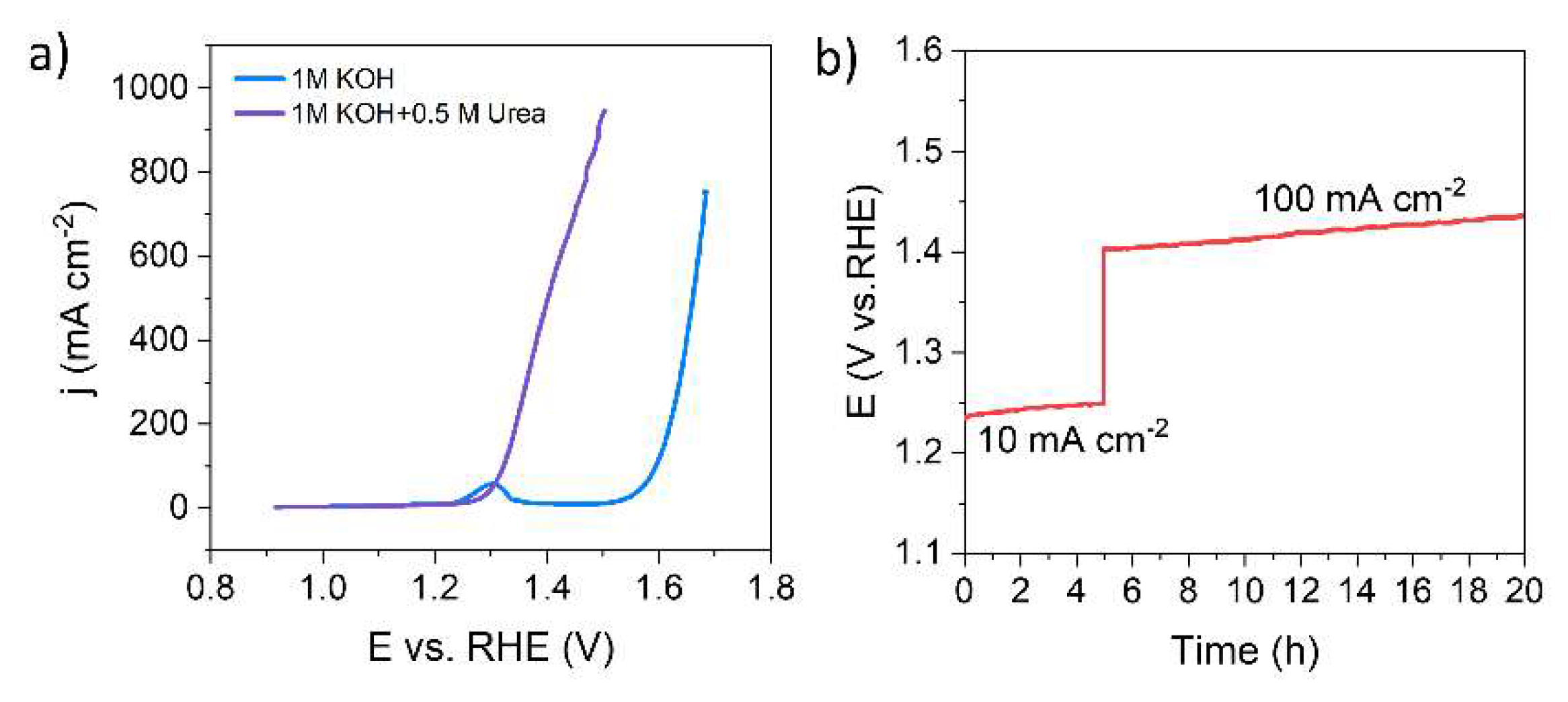
Figure 5a shows a comparison of the LSV curves of NiCo-LDH deposited on MnO2/NF with or without the addition of urea in the electrolyte. It is evident that the LSV curve for UOR (with urea) emerges at a lower potential region with a shift of up to 300 mV compared to that of OER (without urea). This finding suggests the great promise of adopting UOR as an alternative anodic reaction in energy-saving hydrogen production. Constant-current chronopotentiometry measurement was carried out to evaluate the stability of the catalyst. Figure 5b displays the potential recorded for a time course of 20 h at the current densities of 10 and 100 mA cm-2. As can be seen, the potential experienced only a slight change at each current density, indicating that the MnO2@NiCo-LDH possesses excellent catalytic stability for UOR.
5. Conclusions
In summary, this study focused on the development of a precisely engineered hierarchical structure of MnO2@NiCo-LDH nanoarrays for effective electrocatalytic urea oxidation. The synthesized hybrid catalyst showcased improved reaction kinetics, which can be attributed to the combined advantages of the high electrical conductivity of MnO2 nanosheets and the intrinsic activity of the NiCo-LDH deposits. Additionally, the three-dimensional hierarchical architecture provided ample space for efficient mass transport during the reaction. Remarkably, the resulting catalyst exhibited an onset potential of only 1.228 V for UOR and required only 1.326 V to achieve a current density of 100 mA cm-2. Overall, the controlled fabrication of hierarchically structured nanoarrays offers a potential pathway for efficient electrocatalytic urea oxidation and holds great promise for application in energy conversion and storage systems.
Supplementary Materials
The following supporting information can be downloaded at the website of this paper posted on Preprints.org, Figure S1: Potential calibration of the SCE and Hg/HgO against a Pt|H2(g) electrode in 1 M KOH; Figure S2: SEM images of MnO2 nanosheet arrays grown on nickel foam (NF); Figure S3: SEM image of CoNi-LDH deposited on NF; Figure S4: EDS spectrum of the mapping area; Figure S5: Enlarged view of the UOR LSV curves of different catalysts; Figure S6: CV curves of a) MnO2@NiCo-LDH, b) NiCo-LDH/NF, c) MnO2/NF, and d) NF at different potential scan rates at the non-Faradaic region; Figure S7: LSV curves of UOR by MnO2@NiCo-LDH with different deposition times; Table S1: Performance comparison of UOR catalysts reported recently.
Author Contributions
Conceptualization, Wenbo Xu, Guofa Dong and Ming Fang; Data curation, Wenjun Liu and Guofa Dong; Formal analysis, Wenjun Liu and Ming Fang; Investigation, Wenjun Liu and Wenbo Xu; Methodology, Wenbo Xu, Guofa Dong and Ming Fang; Resources, Guofa Dong and Ming Fang; Supervision, Ming Fang; Validation, Wenbo Xu; Writing – original draft, Ming Fang; Writing – review & editing, Wenjun Liu and Ming Fang. All authors have read and agreed to the published version of the manuscript.” Please turn to the CRediT taxonomy for the term explanation. Authorship must be limited to those who have contributed substantially to the work reported.
Funding
This research was funded by the Natural Science Foundation of Shenzhen City, grant number JCYJ20190808141015383; the Natural Science Foundation of Fujian Province, grant number 2022I0043; and the Science and Technology Project of Fuzhou, Grant No. 021-S-237.
Acknowledgments
We thank the Instrumental Analysis Center of Shenzhen University for their assistance in TEM imaging.
References
- Chu, S.; Majumdar, A. Opportunities and Challenges for a Sustainable Energy Future. Nature 2012, 488, 294–303. [Google Scholar] [CrossRef] [PubMed]
- Taibi, E.; Miranda, R.; Vanhoudt, W.; Winkel, T.; Lanoix, J.-C.; Barth, F. Hydrogen from Renewable Power: Technology Outlook for the Energy Transition Available online: https://www.h2knowledgecentre.com/content/policypaper1306.
- Shih, A.J.; Monteiro, M.C.O.; Dattila, F.; Pavesi, D.; Philips, M.; da Silva, A.H.M.; Vos, R.E.; Ojha, K.; Park, S.; van der Heijden, O.; et al. Water Electrolysis. Nat. Rev. Methods Primer 2022, 2, 1–19. [Google Scholar] [CrossRef]
- Yu, Z.-Y.; Duan, Y.; Feng, X.-Y.; Yu, X.; Gao, M.-R.; Yu, S.-H. Clean and Affordable Hydrogen Fuel from Alkaline Water Splitting: Past, Recent Progress, and Future Prospects. Adv. Mater. 2021, 33, 2007100. [Google Scholar] [CrossRef] [PubMed]
- Miller, H.A.; Bouzek, K.; Hnat, J.; Loos, S.; Bernäcker, C.I.; Weißgärber, T.; Röntzsch, L.; Meier-Haack, J. Green Hydrogen from Anion Exchange Membrane Water Electrolysis: A Review of Recent Developments in Critical Materials and Operating Conditions. Sustain. Energy Fuels 2020, 4, 2114–2133. [Google Scholar] [CrossRef]
- Qi, J.; Zhang, W.; Cao, R. Solar-to-Hydrogen Energy Conversion Based on Water Splitting. Adv. Energy Mater. 2018, 8, 1701620. [Google Scholar] [CrossRef]
- Chatenet, M.; Pollet, B.G.; Dekel, D.R.; Dionigi, F.; Deseure, J.; Millet, P.; Braatz, R.D.; Bazant, M.Z.; Eikerling, M.; Staffell, I.; et al. Water Electrolysis: From Textbook Knowledge to the Latest Scientific Strategies and Industrial Developments. Chem. Soc. Rev. 2022, 51, 4583–4762. [Google Scholar] [CrossRef]
- Xiao, Z.; Qian, Y.; Tan, T.; Lu, H.; Liu, C.; Wang, B.; Zhang, Q.; Sarwar, M.T.; Gao, R.; Tang, A.; et al. Energy-Saving Hydrogen Production by Water Splitting Coupling Urea Decomposition and Oxidation Reactions. J. Mater. Chem. A 2022, 11, 259–267. [Google Scholar] [CrossRef]
- Geng, S.-K.; Zheng, Y.; Li, S.-Q.; Su, H.; Zhao, X.; Hu, J.; Shu, H.-B.; Jaroniec, M.; Chen, P.; Liu, Q.-H.; et al. Nickel Ferrocyanide as a High-Performance Urea Oxidation Electrocatalyst. Nat. Energy 2021, 6, 904–912. [Google Scholar] [CrossRef]
- Qin, H.; Ye, Y.; Li, J.; Jia, W.; Zheng, S.; Cao, X.; Lin, G.; Jiao, L. Synergistic Engineering of Doping and Vacancy in Ni(OH)2 to Boost Urea Electrooxidation. Adv. Funct. Mater. 2023, 33, 2209698. [Google Scholar] [CrossRef]
- Ji, Z.; Song, Y.; Zhao, S.; Li, Y.; Liu, J.; Hu, W. Pathway Manipulation via Ni, Co, and V Ternary Synergism to Realize High Efficiency for Urea Electrocatalytic Oxidation. ACS Catal. 2022, 12, 569–579. [Google Scholar] [CrossRef]
- Cai, M.; Zhu, Q.; Wang, X.; Shao, Z.; Yao, L.; Zeng, H.; Wu, X.; Chen, J.; Huang, K.; Feng, S. Formation and Stabilization of NiOOH by Introducing α-FeOOH in LDH: Composite Electrocatalyst for Oxygen Evolution and Urea Oxidation Reactions. Adv. Mater. 2023, 35, 2209338. [Google Scholar] [CrossRef] [PubMed]
- Sun, H.; Liu, J.; Kim, H.; Song, S.; Fei, L.; Hu, Z.; Lin, H.-J.; Chen, C.-T.; Ciucci, F.; Jung, W. Ni-Doped CuO Nanoarrays Activate Urea Adsorption and Stabilizes Reaction Intermediates to Achieve High-Performance Urea Oxidation Catalysts. Adv. Sci. 2022, 9, 2204800. [Google Scholar] [CrossRef] [PubMed]
- Fang, M.; Xu, W.-B.; Han, S.; Cao, P.; Xu, W.; Zhu, D.; Lu, Y.; Liu, W. Enhanced Urea Oxidization Electrocatalysis on Spinel Cobalt Oxide Nanowires via on-Site Electrochemical Defect Engineering. Mater. Chem. Front. 2021, 5, 3717–3724. [Google Scholar] [CrossRef]
- Fang, M.; Xu, W.-B.; Shen, Y.; Cao, P.; Han, S.; Xu, W.; Zhu, D.; Lu, Y.; Liu, W. Electrochemical Tuning of Nickel Molybdate Nanorod Arrays towards Promoted Electrocatalytic Urea Oxidization. Appl. Catal. Gen. 2021, 622, 118220. [Google Scholar] [CrossRef]
- Tong, Y.; Chen, P.; Zhang, M.; Zhou, T.; Zhang, L.; Chu, W.; Wu, C.; Xie, Y. Oxygen Vacancies Confined in Nickel Molybdenum Oxide Porous Nanosheets for Promoted Electrocatalytic Urea Oxidation. ACS Catal. 2018, 8, 1–7. [Google Scholar] [CrossRef]
- Wang, X.-H.; Hong, Q.-L.; Zhang, Z.-N.; Ge, Z.-X.; Zhai, Q.-G.; Jiang, Y.-C.; Chen, Y.; Li, S.-N. Two-Dimensional Nickel–Cobalt Bimetallic Hydroxides towards Urea Electrooxidation. Appl. Surf. Sci. 2022, 604, 154484. [Google Scholar] [CrossRef]
- Li, D.; Zhou, X.; Liu, L.; Ruan, Q.; Zhang, X.; Wang, B.; Xiong, F.; Huang, C.; Chu, P.K. Reduced Anodic Energy Depletion in Electrolysis by Urea and Water Co-Oxidization on NiFe-LDH: Activity Origin and Plasma Functionalized Strategy. Appl. Catal. B Environ. 2023, 324, 122240. [Google Scholar] [CrossRef]
- Song, W.; Xu, M.; Teng, X.; Niu, Y.; Gong, S.; Liu, X.; He, X.; Chen, Z. Construction of Self-Supporting, Hierarchically Structured Caterpillar-like NiCo2S4 Arrays as an Efficient Trifunctional Electrocatalyst for Water and Urea Electrolysis. Nanoscale 2021, 13, 1680–1688. [Google Scholar] [CrossRef]
- Wang, P.; Bai, X.; Jin, H.; Gao, X.; Davey, K.; Zheng, Y.; Jiao, Y.; Qiao, S.-Z. Directed Urea-to-Nitrite Electrooxidation via Tuning Intermediate Adsorption on Co, Ge Co-Doped Ni Sites. Adv. Funct. Mater. 2023, 33, 2300687. [Google Scholar] [CrossRef]
- Fang, M.; Han, D.; Xu, W.-B.; Shen, Y.; Lu, Y.; Cao, P.; Han, S.; Xu, W.; Zhu, D.; Liu, W.; et al. Surface-Guided Formation of Amorphous Mixed-Metal Oxyhydroxides on Ultrathin MnO2 Nanosheet Arrays for Efficient Electrocatalytic Oxygen Evolution. Adv. Energy Mater. 2020, 10, 2001059. [Google Scholar] [CrossRef]
- Wang, H.; Zhang, J.; Hang, X.; Zhang, X.; Xie, J.; Pan, B.; Xie, Y. Half-Metallicity in Single-Layered Manganese Dioxide Nanosheets by Defect Engineering. Angew. Chem. Int. Ed. 2015, 54, 1195–1199. [Google Scholar] [CrossRef] [PubMed]
- Vedharathinam, V.; Botte, G.G. Direct Evidence of the Mechanism for the Electro-Oxidation of Urea on Ni(OH)2 Catalyst in Alkaline Medium. Electrochimica Acta 2013, 108, 660–665. [Google Scholar] [CrossRef]
- Vedharathinam, V.; Botte, G.G. Understanding the Electro-Catalytic Oxidation Mechanism of Urea on Nickel Electrodes in Alkaline Medium. Electrochimica Acta 2012, 81, 292–300. [Google Scholar] [CrossRef]
Figure 1.
SEM images of MnO2@NiCo-LDH with electrodeposition time of a) 50 s, b) 100 s, c) 150 s, and d) 200 s.
Figure 1.
SEM images of MnO2@NiCo-LDH with electrodeposition time of a) 50 s, b) 100 s, c) 150 s, and d) 200 s.
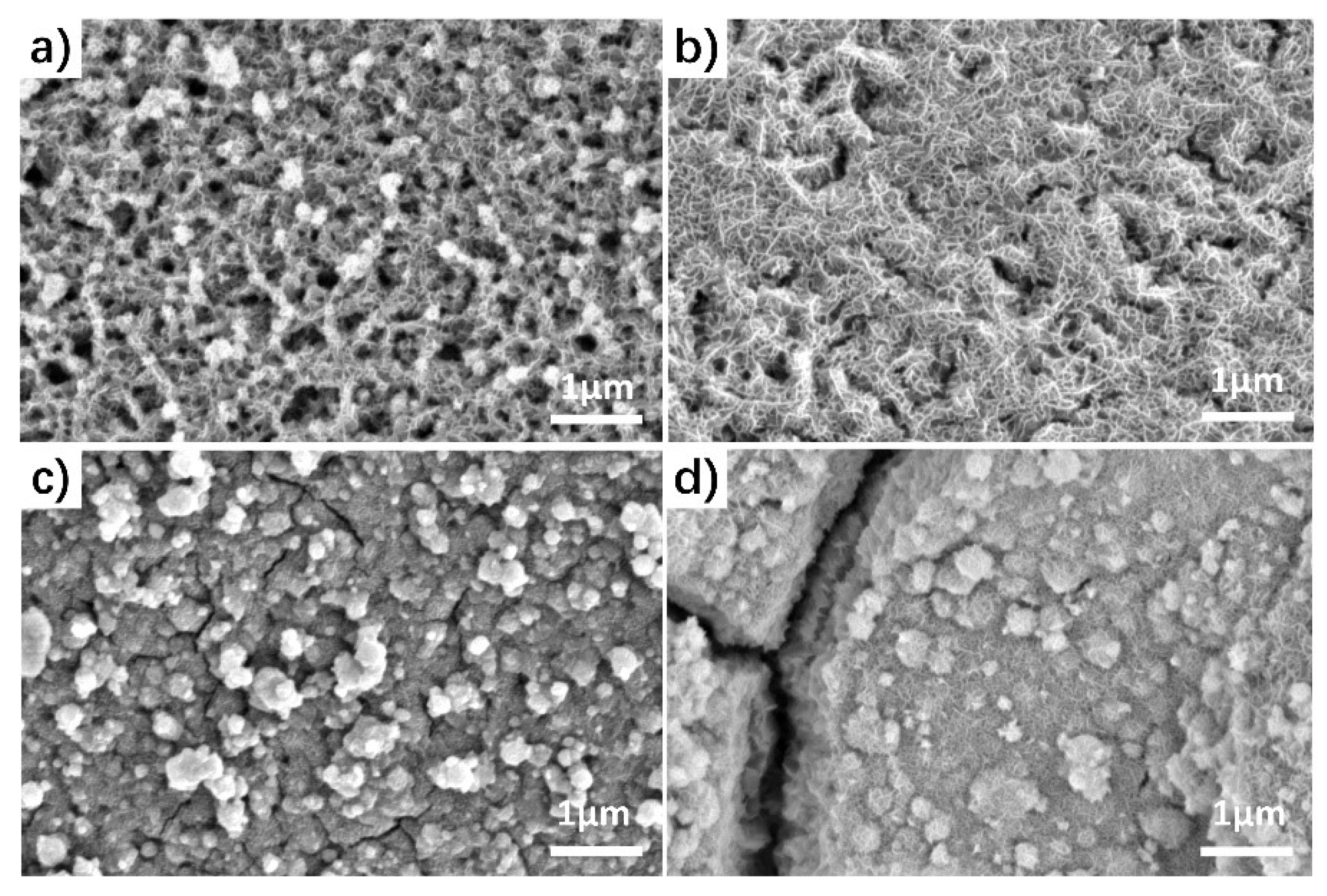
Figure 2.
a) TEM, b) HRTEM, c) SAED pattern, and d-g) HAADF STEM image and the corresponding EDS elemental mapping images of MnO2@NiCo-LDH.
Figure 2.
a) TEM, b) HRTEM, c) SAED pattern, and d-g) HAADF STEM image and the corresponding EDS elemental mapping images of MnO2@NiCo-LDH.
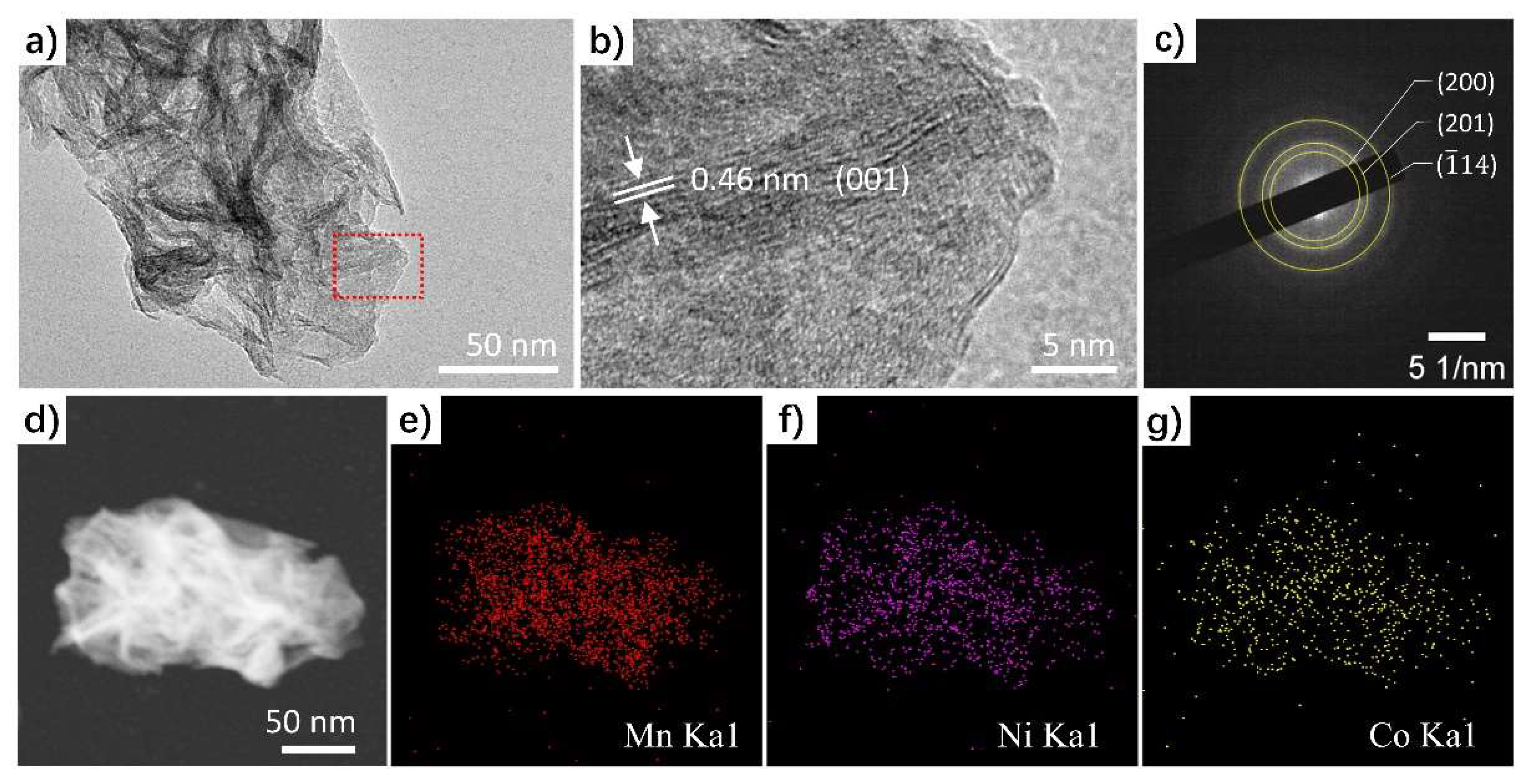
Figure 3.
a) LSV curves, b) performance statistics, c) Tafel curves, d) double layer capacitance calculation, e) EIS spectra of MnO2@NiCo-LDH and the references of NiCo-LDH/NF, MnO2/NF, and NF tested in a solution containing 1 M KOH and 0.5 M urea. f) CV curves of MnO2@NiCo-LDH and bare NF tested in 1 M KOH.

Figure 4.
High-resolution XPS spectra of (a) Ni 2p and (b) Co 2p of the MnO2@NiCo-LDH before and after UOR tests.
Figure 4.
High-resolution XPS spectra of (a) Ni 2p and (b) Co 2p of the MnO2@NiCo-LDH before and after UOR tests.
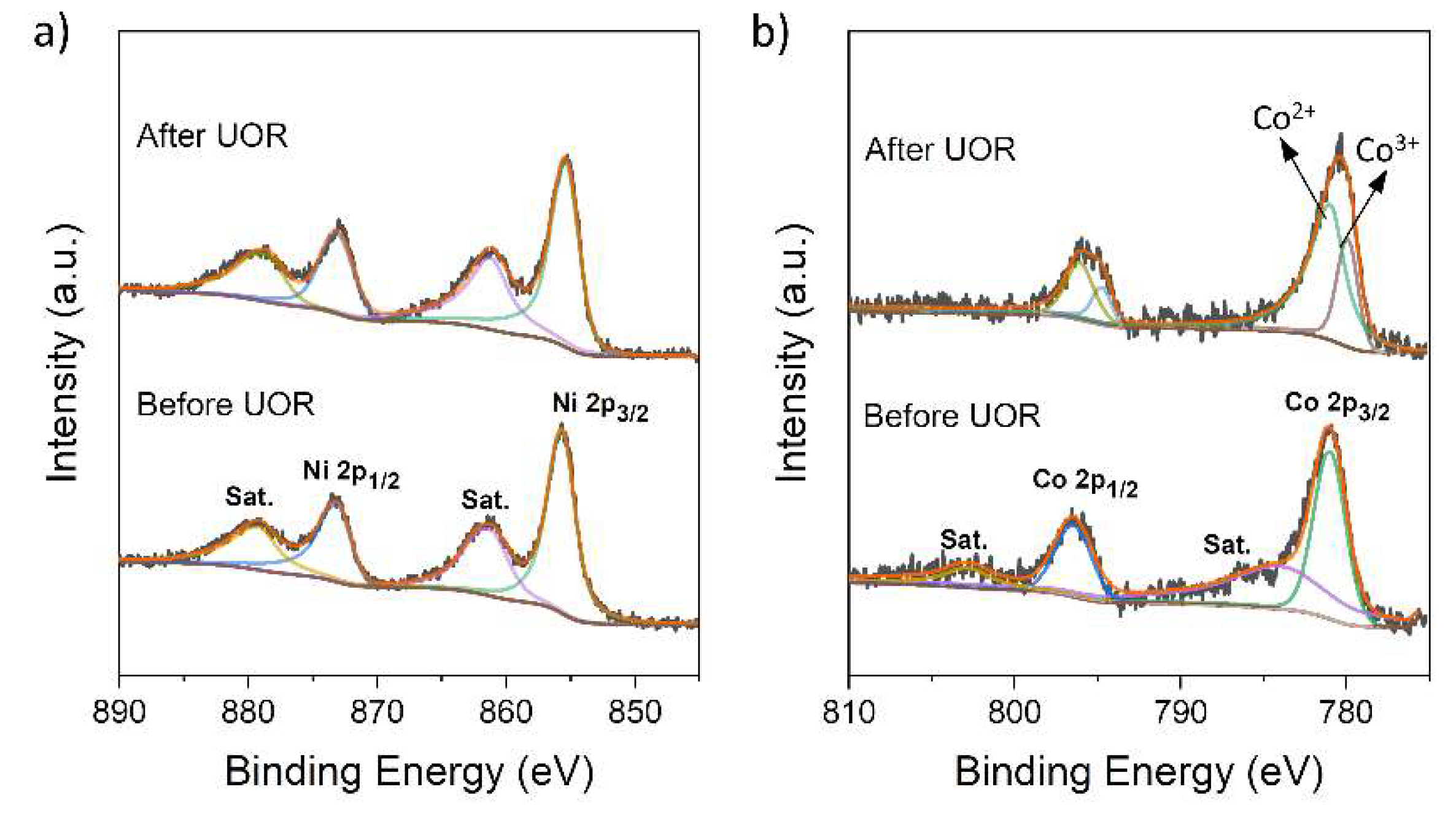
Figure 5.
a) LSV curves of MnO2@NiCo-LDH for UOR and OER. b) Chronopotential curve of MnO2@NiCo-LDH at 10 and 100 mA cm-2.
Figure 5.
a) LSV curves of MnO2@NiCo-LDH for UOR and OER. b) Chronopotential curve of MnO2@NiCo-LDH at 10 and 100 mA cm-2.
Disclaimer/Publisher’s Note: The statements, opinions and data contained in all publications are solely those of the individual author(s) and contributor(s) and not of MDPI and/or the editor(s). MDPI and/or the editor(s) disclaim responsibility for any injury to people or property resulting from any ideas, methods, instructions or products referred to in the content. |
© 2023 by the authors. Licensee MDPI, Basel, Switzerland. This article is an open access article distributed under the terms and conditions of the Creative Commons Attribution (CC BY) license (http://creativecommons.org/licenses/by/4.0/).
Copyright: This open access article is published under a Creative Commons CC BY 4.0 license, which permit the free download, distribution, and reuse, provided that the author and preprint are cited in any reuse.


