Submitted:
14 June 2023
Posted:
16 June 2023
You are already at the latest version
Abstract
This paper will present the torque control design of an AFPMSM, one stator, and one rotor, using an FLC and ANFIS in-wheels fed by a three-level T-type inverter. The Surgeon ambiguous inference file of the FLC controller is built by two input vectors, the stator current error and the derivative of the stator error. These input variables include five membership functions, Negative big (NB), Negative small (NS), Equal zero (ZE), Positive small (PS), and Positive big (PB). The FLC controller is implemented with a 5x5 matrix so that the output stator voltage of the controller is required. The ANFIS controller for the neural network-based feature set and the fuzzy system. The neural network develops the dataset on the stator current error (e) and error integral (∆e). Then, the generated dataset is fed to the fuzzy logic method, and the control rules are developed. This ANFIS controller is caused by the training and testing phases. Finally, the FLC and ANFIS torque controllers are compared with the PI controller. The correctness of the proposed control structured solution is demonstrated by the simulation results of MATLAB/SIMULINK.
Keywords:
AFPMSM
; Fuzzy Logic Controller
; ANN
; NFC
; FOC.
1. Introduction
Electric cars are a revolutionary trend in transportation today. Electric cars have advantages compared to cars with internal combustion engines while eliminating complicated gearboxes and emissions and being environmentally friendly [1,2]. The powertrain structure of electric vehicles tends to use an in-wheel distributed electric drive system consisting of multiple motors, which ensures traction at the front or rear of the car on two or four wheels, making the car becomes a front-wheel drive, rear-wheel drive, or four-wheel drive system [3,4]. This electric powertrain improves the driving performance of electric cars by differentiating between the wheels, makes full use of vehicle energy, improves transmission efficiency, increases range, eases braking, has good heat dissipation, and is more convenient for installation and maintenance [5,6]. The axial flux permanent magnet synchronous motor (AFPMSM) is widely used for electric buses and tanks in the in-wheel motor drive system. Because this motor has short shaft length characteristics, the rotor is lightweight, has good vibration resistance, and has a long service life, thus improving the engine’s reliability and safety and reliability [7]. Although AFPMSM motors enhance the performance of electric vehicles, each vehicle needs to be installed with multiple motors, resulting in complex system control [8]. In addition, the in-wheel motor increases the vehicle’s cost and has high requirements for the vehicle’s control technology, such as power balancing, electronic differential, and energy recovery. In addition, motor in-wheel for electric cars require a small size, lightweight, small torque, high efficiency, large overload capacity, and wide speed range [9]. Therefore, scientists have been interested in studying the control of traction and torque of the AFPMSM motor in-wheel leading to having the motor’s response transmit traction from the motor to the wheels as required. Torque and speed controllers are controlled based on direct torque control (DTC) and based on field-oriented control (FOC). In addition, these controllers are designed by linear and nonlinear control methods such as PI, LQR, Dead beat, sliding control, flatness, fuzzy, [10,11,12,13] or hybrid controller such as fuzzy-neural, fuzzy-sliding mode control [14,15,16,17]. This research results only stop to evaluate the effectiveness of each solution for torque and speed control in the case of AFPMSM motors operating with unchanged load torque or motor parameters. However, the torque response has a slight pulsation, and the actual speed response quickly and accurately tracks the required speed [18,19,20]. Thereby, it is found that researching intelligent control solutions to improve an AFPMSM motor torque integrated with electric car in-wheel, combined with the required torque component by the physical properties of the vehicle car. For example, brake pedals, accelerator pedals, the impact of road inclination, and wind resistance. Therefore, these parameters are necessary to improve the performance and torque of electric vehicles.
This paper will present the control design of a in-wheel AFPMSM motor, one stator, and one rotor, using a fuzzy logic and neuro-fuzzy controller for electric vehicle. In this FLC controller, the Surgeon ambiguous inference file is built by two input vectors, the stator current error and the derivative of the stator error. These input variables include five membership functions, Negative big (NB), Negative small (NS), Equal zero (ZE), Positive small (PS), and Positive big (PB). The fuzzy logic controller is implemented with a 5x5 matrix so that the output stator voltage of the controller is met as required [21,22,23]. Other hand, NFC controller for the neural network-based feature set and the fuzzy system. A forward-looking structured network characterizes the neural network, and the training algorithm is back-propagated. The data is trained based on the network error in the back-propagation training algorithm. The network error is the difference between the target and actual values. Therefore, an appropriate control model can be developed. The proposed fuzzy inference system model is based on the Sugeno model containing a set of rules. The vague concept consists of three steps: fuzzy, rule-based decision-making, and defuzzification. In this hybrid system, the neural network develops the dataset on the deviation between the natural is line with the set is (e) and its integral (∆e). Then, the generated dataset is fed to the fuzzy system, and the control rules are developed [24,25]. This NFC controller is caused by the training and testing phases. The FLC and NFC torque controllers are compared with the PI controller.
The present paper consists of six main parts. First, the state model of the electric car traction transmission system is shown in part 2. Then, based on mathematical equations, design torque controller by the FLC and NFC method in parts 3 &4. The theory’s correctness will be proved by the simulation results and evaluation of the current, speed, and torque responses between the proposed controller and compared with the PI controller in part 5. Finally, concluding the contributions. The research results and recommendations for future solutions to improve and enhance the torque response with simple controller design theory and experimental implementation
2. Thematical model and control of electric car power system
2.1. Mathematical model of the AFPMSM motor
It is possible to utilize the standard PMSM model for an AFPMSM. The stator parameters change between the two models, such as the inductor calculation. Furthermore, the Back-EMF produced by an excitation coil and a permanent magnet is same. Therefore, the radial PMSM of a permanent axial flux magnet synchronous motor and the model are mathematically related.
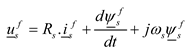
The stator voltage equation in the d-q frame of reference is given by Eq. (1).
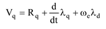
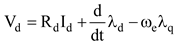
The stator voltage math as follow:
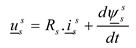
Where:Rs: stator resistance; : stator flux
Then, covert Eq. (3) from the phase winding system of the stator to the coordinate system quasi-rotor flux:
The relationship between stator and rotor flux is described:
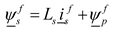
In Eq. (5), is the polar flux vector. Since the axis of the coordinate system coincides
with the axis of the polar flux, the perpendicular component (q axis component)
of will be zero. Thus, the flux vector has
only real components.

Equation of flux components such as:
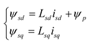
Substitute two Eq. (5) and Eq. (6) into Eq. (4) and pass through the dq coordinate system to have the system of equations of PMSM motor:
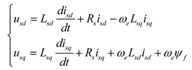
Where: isd ; isq are stator current in the d-q coordinate axis.
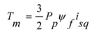
The equation for calculating the torque of the motor is described:
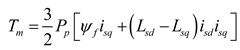
The motor’s torque comprises two components: the primary component and the reactive component. In order to
create a control system, the stator current vector must be adjusted so that the
vertical current vector is parallel to the polar flux. Therefore, there is a
torque-generating current component, not a magnetizing current component. The
following equation gives the motor torque.
2.2. Mathematical model of electric vehicle
The gearbox model shows the angular speed and torque relationships according to the gear ratio as
shown in the Eq. (9):
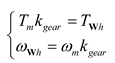
Where: Tm is motor torque;the torque
acting on the wheel; with Ti = TWhis the load moment J
is the moment of inertia of the motor.
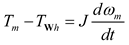
The equation of newton’s second law in the rotation of the motor, as shown in the Eq. (12):
Drive wheel model is expressed in the Eq. (13):
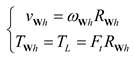
The vehicle will act on the road surface with a force of F while the wheel is resting on it with a force of N and is being propelled by a torque of Twh. In contrast, the road surface will act against the vehicle with a point of the same value in the opposite direction of Ft. The reasonable force that propels the car at speed in this scenario is the frictional force or Ft.
The frictional force is calculated by Eq. (14):

Where: μ
Vehicle equation of motion with external force components the following equation results from applying Newton’s second law to the parts of the outside force operating on the vehicle's body
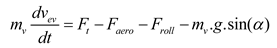
Air resistance as show in Eq. (16):
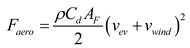
In some cases, in simulations, the wind speed can be set
Rolling resistance exists in the case of an
underinflated tire are expressed in the Eqs. (17), (18).
 where: FzY is the vertical surface reaction, is the rolling resistance coefficient.
3. FLC torque controller design
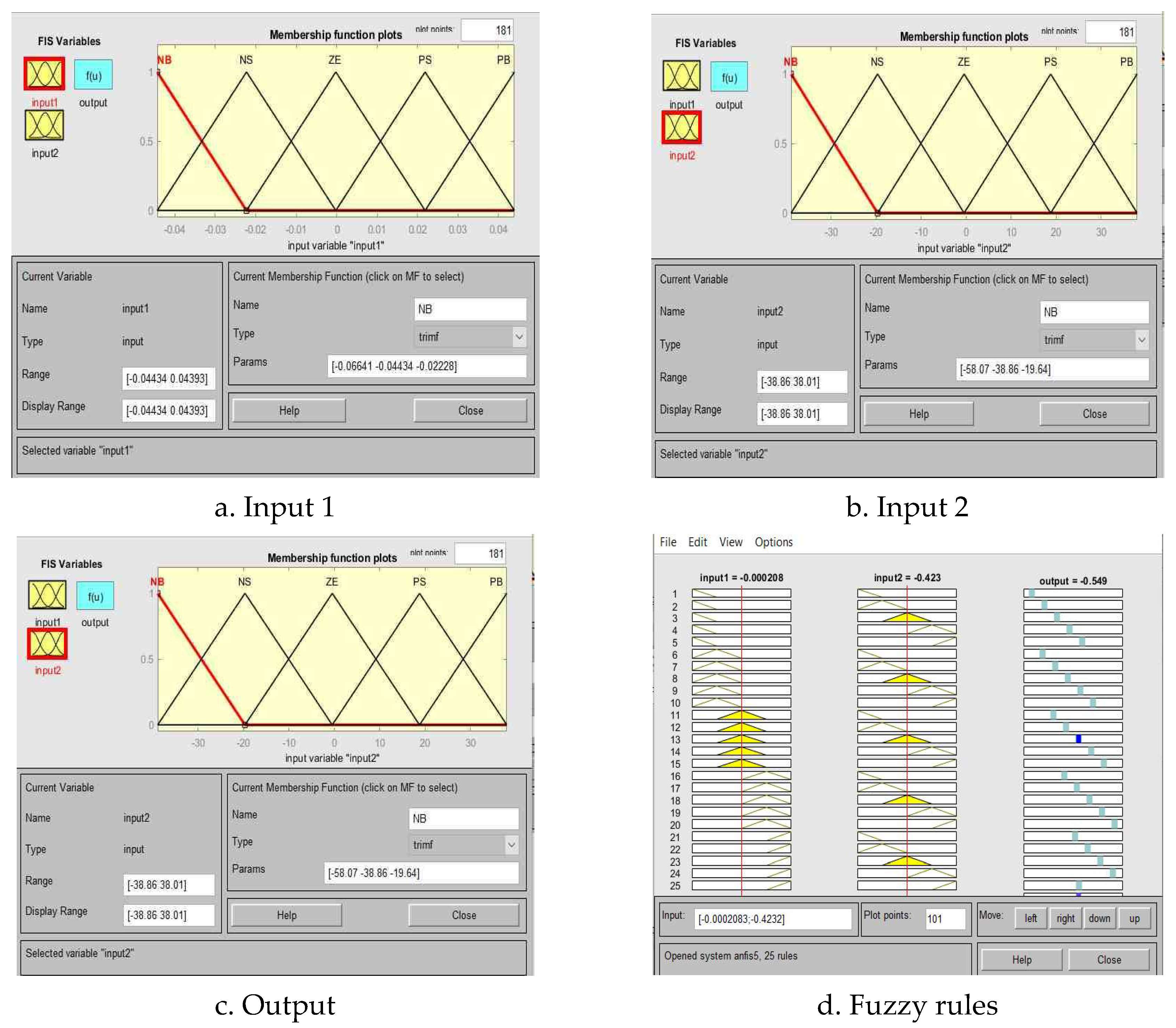
By calculating the necessary voltage usd, usq, the fuzzy logic controller controls the system so that the difference between current isd and isq is as tiny as possible. The exactly planned isd and isq stator currents are used here to regulate the motor’s torque control current. This paper will outline the modern controller design for the isd. The control strategy for an AFPMSM motor, one stator, and one rotor utilizing a FLC controller for electric car in-wheels is presented in this work. The stator current error and the derivative of the stator error are used as the two input vectors in this controller to build the Surgeon ambiguous inference file. Five membership functions are included in these input variables: Positive big (PB), Positive small (PS), Equal zero (ZE), and Negative big (NB) (PB). As seen in Table 1 and Figure 1 the fuzzy logic controller is constructed using a 5x5 matrix.
The fuzzy logic control rule consists of 25 rules, which are implemented as follows:
- If (input 1 is NB) and (input 2 is NB), then (output is NB)
- If (input 1 is NB) and (input 2 is NS), then (output is NB)
- If (input 1 is NB) and (input 2 is ZE), then (output is NB)
- …………………..
- If (input 1 is PB) and (input 2 is PB), then (output is PB)
4. NFC torque controller design
The neuro-fuzzy controller (NFC) is a combination of neural network and fuzzy logic implemented according to the structure of Figure 2. This hybrid controller is proposed to satisfy the required voltage, considering the influence of noise. This hybrid controller reduces system complexity and improves torque response on demand.
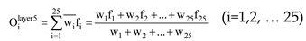
The structure of the NFC controller consists of five layers: input layer, input member function layer, rule layer, output member function layer, and output layer. Decision tree fuzzy interference is to classify the data into one of the linear regression models to minimize the total squared error (SSE) is calculated by Eq. (19):
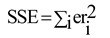
Where n is the number of input variables; P is the fuzzy division for each input variable, and eri2 is the error between the desired and actual output.
The two-input Sugeno fuzzy model is given in Figure 3.
The NFC controller for current isq consists of two inputs, the difference (e) between isq* anq isq, and error integral (∆e). The input signal is fuzzy into five triangular membership functions, negative big (NB), negative small (NS), equal zero (ZE), positive small (PS), and positive big (PB). The 5x5 = 25 fuzzy rules that combine with the output according to the two-input first-order Surgeon model:
- If x1 is A1 (NB) and x2 is B1 (NB), then f1 = p1e + q1∆e + r1
- If x1 is A1 (NB) and x2 is B2 (NS), then f2 = p2e + q2∆e + r2
- If x1 is A1 (NB) and x2 is B3 (ZE), then f3 = p3e + q3∆e + r3
- If x1 is A1 (NB) and x2 is B4 (PS), then f4 = p4e + q4∆e + r4
- If x1 is A1 (NB) and x2 is B5 (PB), then f5 = p5e + q5∆e + r5
- …
- If x1 is A25 (PB) and x2 is B25 (PB), then f25 = p25e + q25∆e + r25
Where: Ai and Bi are the premise fuzzy sets, and the parameters pi, qi and ri are the fuzzy design parameters calculated during the training process (i=1, 2,…n). The two-input and one-output NFC structure is given as follows:
The first layer 1: The fuzzy process takes place the input signal is blurred into five triangular membership functions. For each output value of the first layer, we can quickly compute a membership function value denoted μ.
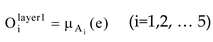
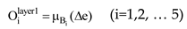
Where: i is the membership level of the dataset (A1, A2, B1, B2) and, is the output of the i node in layer 1.
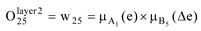
The second layer is to check the weight of each function. This layer takes input values from the first layer and acts as optimization functions to represent data sets of corresponding input variables. The output of this node is described:
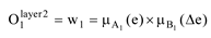
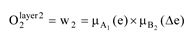
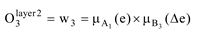
…………………..
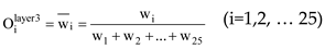
3rd layer: This is a rule layer and takes input from the previous layer. Each node (each neuron) in this layer performs conditional matching of the rules. This layer calculates the activation level of each rule, and the number of layers is equivalent to the number of fuzzy rules. Each node of this class computes a weight that will be normalized. Layer 3 nodes calculate the ratio of the rule’s activation strength to the sum of all active rules:
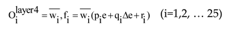
4th layer: Defuzzification provides output values due to inference rules. The node output is calculated by multiplying the layer 3 output value and the corresponding f-rule:
5th layer: the output layer aggregates all inputs coming from the 4th layer and converts fuzzy classification results into the required value:
5. Simulation results
5.1. Building trajectories of accelerator, brake and operating modes of electric vehicles
The trajectories of accelerators and brakes of electric cars are built according to the function y = F (x1, x2, …xn). The trajectories of the accelerator and brakes of electric cars are created, as shown in Figure 5.
Where F is a function that can be obtained experimentally, the output value is calculated by looking up or interpolating the table of deals you define using the block parameters according to the method, such as linear (linear gradient), Lagrange (Linear Lagrange), point closest, block spline and Akima spline interpolation methods. The Fcos function can range in size from 1 to 30 values. Besides the first input defining the dimension breakpoints (rows), the second input defines the dimension breakpoints (columns). Trajectories of the accelerator and brake of electric vehicles are determined as shown in Figure 6.
5.2. Simulation results for PI, FLC and NFC torque controllers
The control structure of the traction drive system for electric cars using the in-wheel AFPMSM motor is shown in Figure 7. Simulation parameters are determined in Table 2.
Evaluating the effectiveness of the controller for the traction transmission system for electric cars using an in-wheel AFPMSM motor, the system is simulated on MATLAB with the following simulation scenario:
- Assume the speed of the wind is 0.
- The car moves on a flat road, but at t= 3.5s to 4.3s, the car goes downhill.
- At t = 0s, the car starts to accelerate the accelerator value increases from 0 to 1 after 0.45s. Torque reaches a maximum of 205 Nm and remains for 2s.
The torque gradually decreases to the value -205 Nm and returns to the value 0 at time t= 4.66s.
5.2.1. Subsubsection Ld, Lq parameters of the in-wheel AFPMSM motor remain unchanged
The PI controller is calculated with a set of integral and gains parameters, as shown in Table 3. The stator current responses of the FLC, and NFC torque controller are compared with the PI controller shown in Figure 8, Figure 9 and Figure 10. The evaluation table of criteria of stator current response of PI, FLC, and NFC controllers is presented in Table 4.
Figure 8, Figure 9 and Figure 10 show that the stator current response or three controllers is fast (0.4s) and accurate in the steady-state mode. However, the proposed FLC and NFC controllers perform better than the PI controller in over-regulating (no over-throttling). In contrast, the PI controller with an over-regulating current at an over-regulating time is 10%.
The torque and speed responses of the FLC, and NFC torque controllers are compared with the PI controller shown in Figure 11, Figure 12 and Figure 13. The evaluation table of the torque and speed response criteria of the controller PI, FLC and NFC controllers are shown in Table à6. The speed response of the electric car transmission system is shown in Figure 14.
Figure 11, Figure 12 and Figure 13 show that the torque of the three controllers has the same form as the isq stator current. The NFC controller has a torque ripper response that is the best of the two controllers (3%). Other hand, the FLC controllers for torque ripper response have less pulse rate (5%) than the PI controller (8%).
In addition, the actual speed response of the electric car of the two controllers is in line with the set requirements, and the speed response does not have too much speed adjustment at starting, accelerating, and decelerating (Figure 14).
5.2.2. Ld , Lq parameters of the in –wheel AFPMSM motor changed by 20%
The stator current responses of the FLC and NFC torque controllers are compared with PI shown in Figure 15, Figure 16 and Figure 17. The evaluation table of criteria of stator current response of PI, FLC, and NFC torque controllers is presented in Table 6.
The results of Figure 15, Figure 16 and Figure 17 show that the stator current response of all three methods is exact (0.5s) and is accurate in steady-state mode (the actual signal follows the set signal). However, the proposed NFC controller gives better results than the PI, and FLC controllers (no over-tuning), while the PI controller with isd over-regulating current is 10%, and isq is 20%, FLC controller with current regulation isd, isq is 5%.
5. Conclusions
The research has successfully designed an in-wheel AFPMSM motor torque controller for a traction drive system using an FLC and NFC controllers by MATLAB simulation. Two controllers are compared with the PI controller. Through simulation results when the motor parameters are unchanged and Ld, Lq change by 20%, it is found that the torque response of the FLC and NFC controllers has a fast response and follows the set value. In contrast, the controller has a slower response PI control and high throttling transients. In addition, according to the NFC controller, the resulting torque amplitude is smaller than that of the PI and FLC control methods. Finally, the stability of the PI controller destabilizes when the motor parameter changes. The FLC and NFC controllers give better system stability than the PI control structure. However, these FLC and NFC controllers have a complicated design, thus it is necessary to study simple, intelligent control solutions in theoretical implementation and experimental performance in the future.
Acknowledgments
This research is funded by University of Transport and Communications (UTC) under grant number T2023-DT-001TĐ
References
- X. Zhang, D. Göhlich and J. Li, "Energy-Efficient Toque Allocation Design of Traction and Regenerative Braking for Distributed Drive Electric Vehicles," in IEEE Transactions on Vehicular Technology, vol. 67, no. 1, pp. 285-295, Jan. 2018. [CrossRef]
- N. Mutoh, "Driving and Braking Torque Distribution Methods for Front- and Rear-Wheel-Independent Drive-Type Electric Vehicles on Roads With Low Friction Coefficient," in IEEE Transactions on Industrial Electronics, vol. 59, no. 10, pp. 3919-3933, Oct. 2012. [CrossRef]
- X. Yuan and J. Wang, "Torque Distribution Strategy for a Front and Rear-Wheel-Driven Electric Vehicle," in IEEE Transactions on Vehicular Technology, vol. 61, no. 8, pp. 3365-3374, Oct. 2012. [CrossRef]
- R. Wrobel, J. Goss, A. Mlot and P. H. Mellor, "Design Considerations of a Brushless Open-Slot Radial-Flux PM Hub Motor," in IEEE Transactions on Industry Applications, vol. 50, no 3, pp. 1757-1767, May-June 2014. [CrossRef]
- Wei Xu; Jianguo Zhu; Youguang Guo; Shuhong Wang; Yi Wang; Zhanghai Shi,” Survey on electrical machines in electrical vehicles”, 2009 International Conference on Applied Superconductivity and Electromagnetic Devices.
- Mohamed Arbi Khlifi, Marwa Ben Slimene, Ahmad Alradedi, Salah,” Al Ahmadi “Investigation of a Leakage Reactance Brushless DC Motor for DC Air Conditioning Compressor Engineering”, Technology & Applied Science Research, Vol. 12, No. 2, 2022.
- Merve Yıldırım, Mehmet Polat, H. Kurum,” A survey on comparison of electric motor types and drives used for electricvehicles,” 16th International Power Electronics and Motion Control Conference and Exposition Antalya, Turkey 21-24 Sept 2014.
- Tahir Aja Zarma, Ahmadu Adamu Galadima, Aminu A. Maruf,” Review of Motors for Electrical Vehicles”, October 2019 Journal of Scientific Research and Reports.
- Garcia, X. D. T. et al. Comparison between FOC and DTC Strategies for Permanent Magnet Synchronous Motors. Advances in Electrical and Electronic Engineering 5, 76-81, (2011).
- Pooja Bhatt, Hemant Mehar, Manish Sahajwani,” Electrical Motors for Electric Vehicle – A Comparative Study,” Proceedings of Recent Advances in Interdisciplinary Trends in Engineering & Applications (RAITEA) 2019.
- W. Yu and C. Gu, "Dynamic analysis of a novel clutch system for in-wheel motor drive electric vehicles," in IET Electric Power Applications, vol. 11, no. 1, pp. 90-98, 1 2017. [CrossRef]
- A. Darba, M. Esmalifalak and E. S. Barazandeh, Implementing SVPWM technique to axial flux permanent magnet synchronous motor drive with internal model current controller, 2010 4th International Power Engineering and Optimization Conference (PEOCO), Shah Alam, Malaysia, (2010), 126-131. [CrossRef]
- Krishnan, Ramu. Electric Motor Drives: Modeling, Analysis, and Control, Prentice-Hall Of India Pvt. Limited, (2001).
- Phạm Thi Giang, Vo Thanh Ha*, Vu Hoang Phương "Drive Control of a Permanent Magnet Synchronous Motor Fed by a Multi-level Inverter for Electric Vehicle Application" - Engineering, Technology & Applied Science Research, Vol. 12, No. 3, June 2022. [CrossRef]
- Vo Thanh Ha, Phạm Thi Giang, Vu Hoang Phương "T-type Multi-Inverter Application for Traction Motor Control" - Engineering, Technology & Applied Science Research, Vol. 12, No. 2, April 2022. [CrossRef]
- Vo Quang Vinh, Vo Thanh Ha ," Improved Torque Ripple of Switched Reluctance Motors using Sliding Mode Control for Electric Vehicles" - Engineering, Technology & Applied Science Research, Vol. 13, No. 1, February 2023. [CrossRef]
- Chunyu Yang; Leping Shen; Linna Zhou,” Fuzzy Sliding Mode Control for Permanent Magnet Synchronous Motors,” 2018 5th International Conference on Information, Cybernetics, and Computational Social Systems (ICCSS). [CrossRef]
- Trong Duy Nguyen, Student Member, IEEE, King-Jet Tseng, Senior Member, IEEE, Shao Zhang, Student Member, IEEE, and Hoan Thong Nguyen, “A Novel Axial Flux Permanent-Magnet Machine for Flywheel Energy Storage System: Design and Analysis”, IEEE Transactions on Industrial Electronics, Vol.58, No.9, September 2011. [CrossRef]
- Trong Duy Nguyen, Gilbert Foo Hock Beng, King-Jet Tseng, Don Mahinda Vilathgamuwa, and Xinan Zhang, “Modeling and Position-Sensorless Control of a Dual-Airgap Axial Flux Permanent Magnet Machine for Flywheel Energy Storage Systems”, Journal of Power Electronics, Vol. 12, No. 5, September 2012. [CrossRef]
- Quang Dich Nguyen and Satoshi Ueno, “Analysis and Control of NonSalient Permanent Magnet Axial-Gap Self-Bearing Motor”, IEEE Transactions on Industrial Electronics, Vol. PP, No. 99, pp. 1-8, 2010 (early access). [CrossRef]
- Garcia, X. D. T. et al. Comparison between FOC and DTC Strategies for Permanent Magnet Synchronous Motors. Advances in Electrical and Electronic Engineering 5, 76-81, (2011).
- S. Nakashima, Y. Inagaki, I. Miki, Sensorless initial rotor position estimation of surface permanentmagnet synchronous motors, IEEE Transactions on Industry Applications, 36, 6, (2000), 1598-1603. [CrossRef]
- Sensorless PMSM Vector Control, Design Reference Manual, freescale , semiconductor , (2009).
- V.K., Arun Shankar & Subramaniam, Umashankar & Sanjeevikumar, P. & Paramasivam, Sathesh, Adaptive Neuro-Fuzzy Inference System (ANFIS) based Direct Torque Control of PMSM driven centrifugal pump. International Journal of Renewable Energy Research. 7, (2017), 1437–1447.
- D. V. Lukichev, G. L. Demidova, A. Y. Kuzin and A. V. Saushev, Application of adaptive Neuro Fuzzy Inference System (ANFIS) controller in servodrive with multi-mass object, 2018 25th International Workshop on Electric Drives: Optimization in Control of Electric Drives (IWED), Moscow, (2018), 1-6. [CrossRef]
- Nagham Farhan, Abdulrahim T. Humod, Fadhil A. Hasan,” Field Oriented Control of AFPMSM for Electrical Vehicle Using Adaptive Neuro-Fuzzy Inference System (ANFIS),” Engineering Engineering and Technology Journal. [CrossRef]
Figure 1.
Inputs, output and fuzzy rules for FLC controller.
Figure 2.
The NFC controller structure.
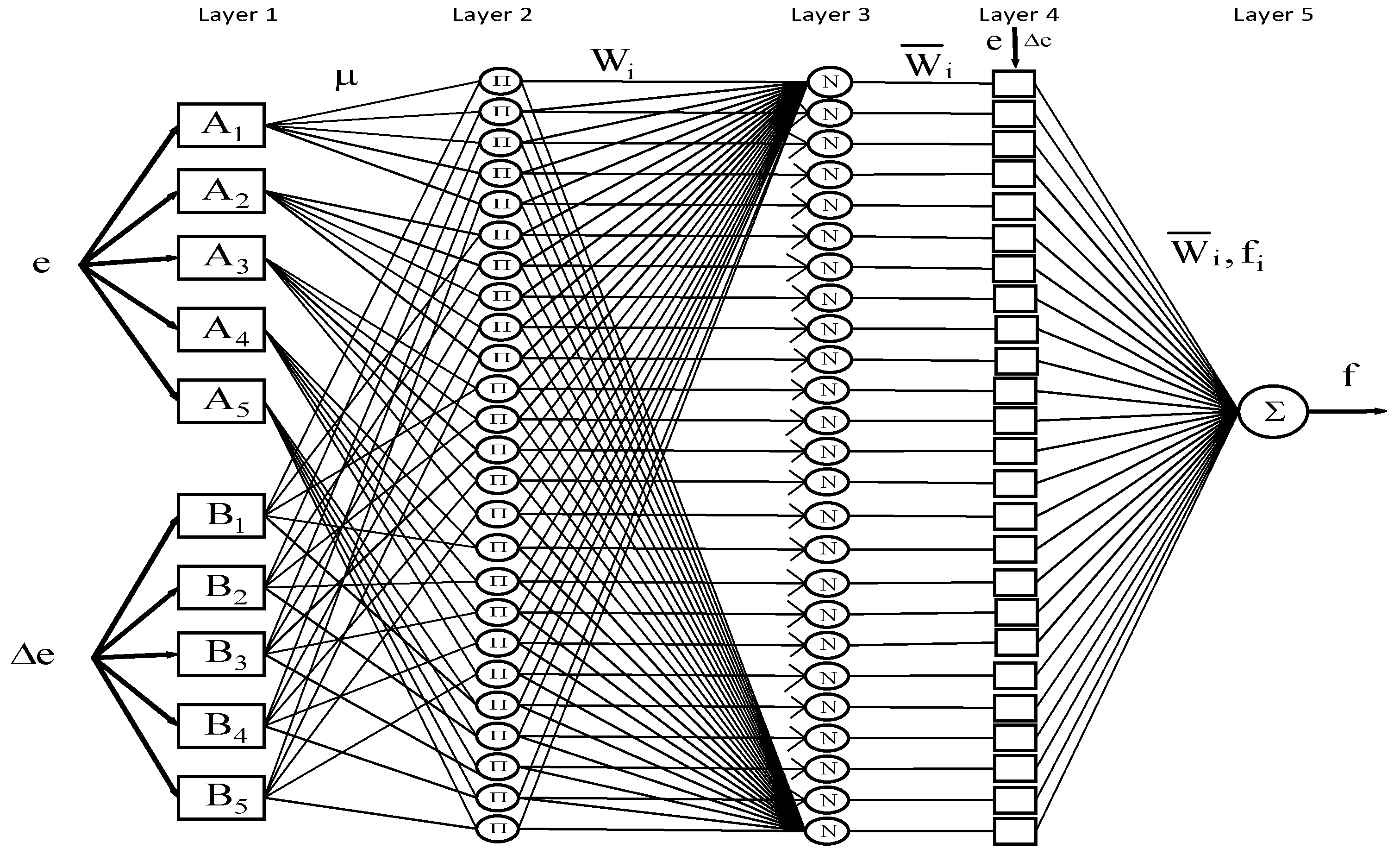
Figure 3.
The two-input Sugeno fuzzy model.
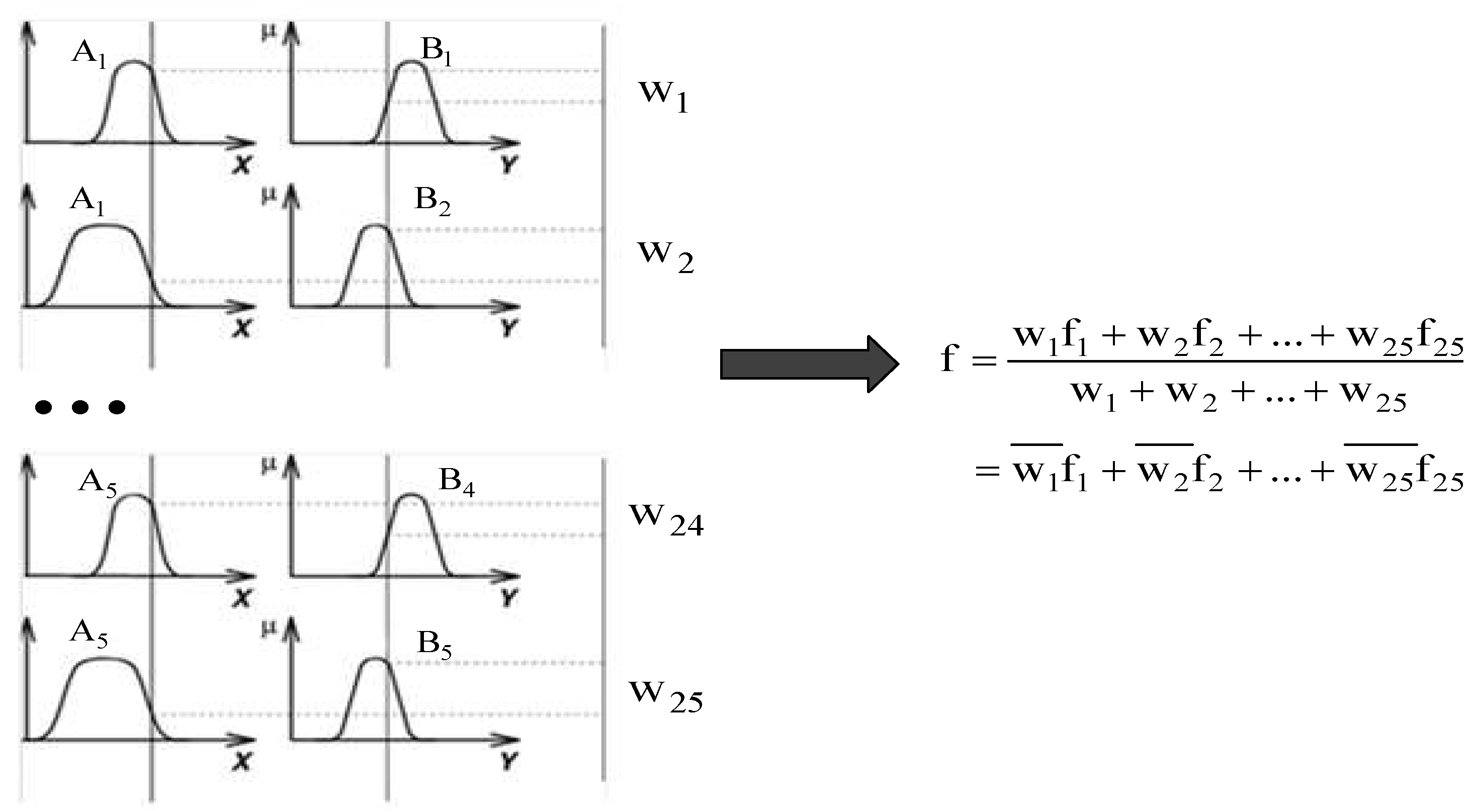
Figure 4.
Two-input for NFC structure.
Figure 5.
The trajectories of the accelerator and brakes.
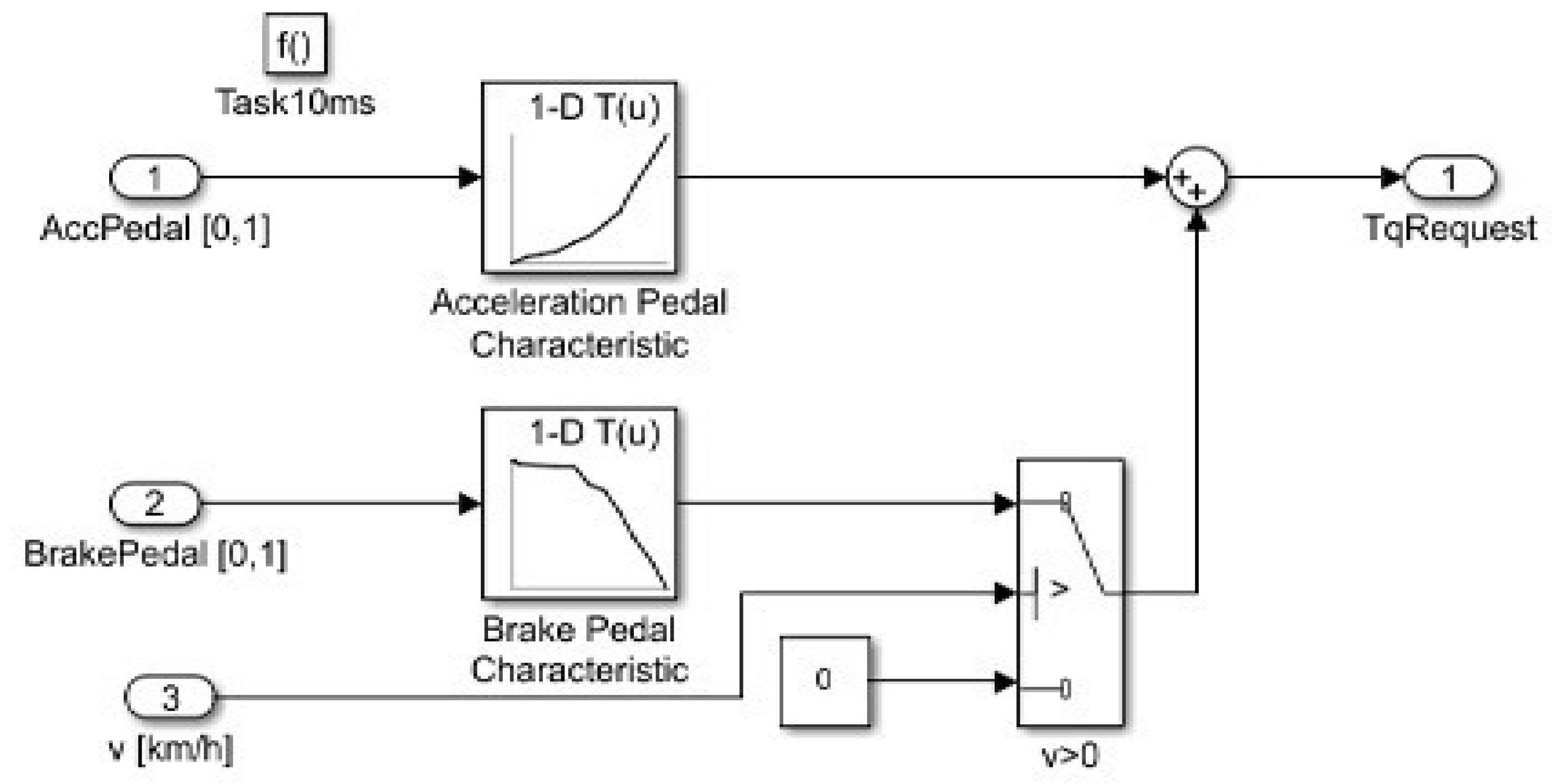
Figure 6.
The parameters trajectories of the accelerator and brakes.
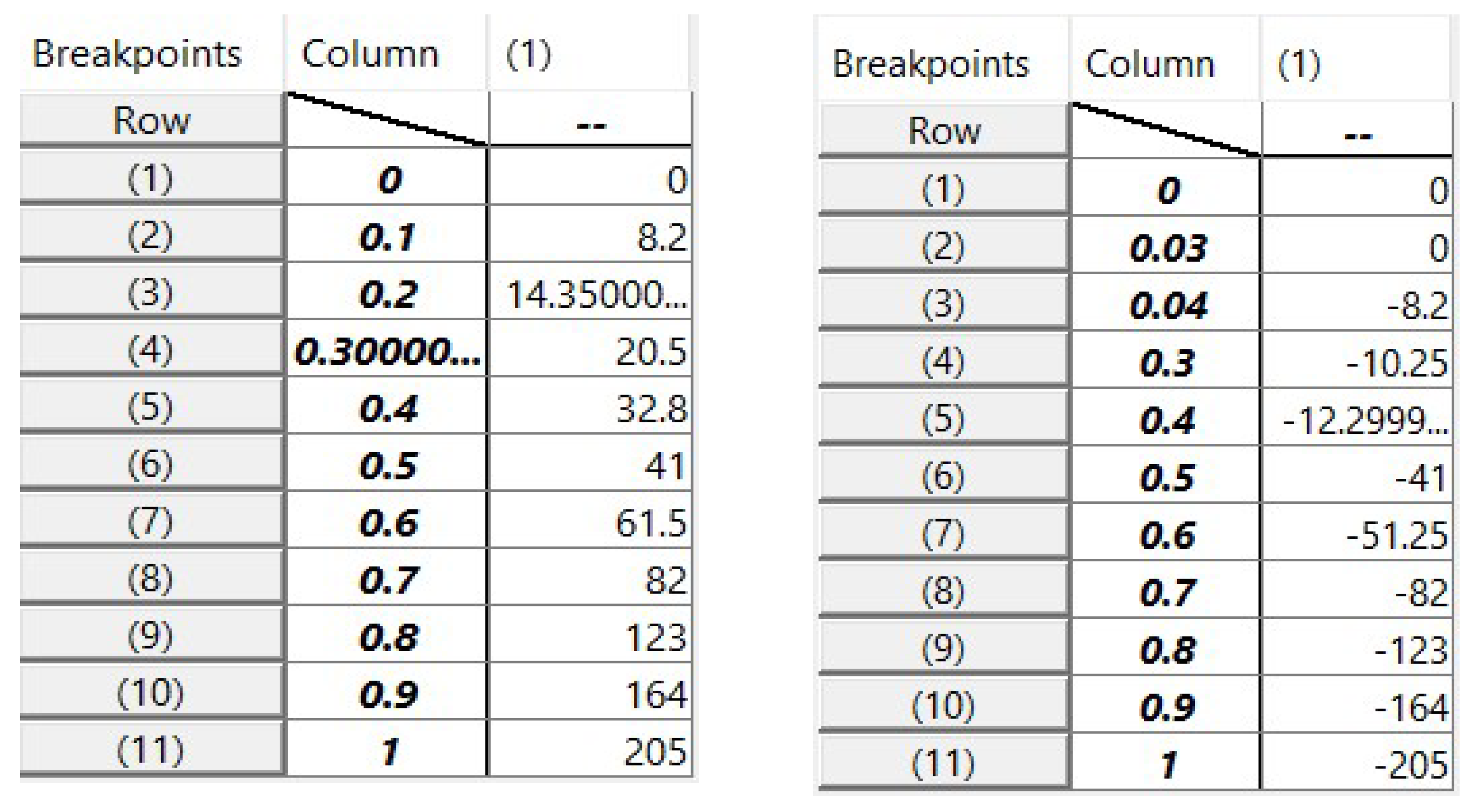
Figure 7.
The control structure for electric cars using an in-wheel AFPMSM motor based FOC method.
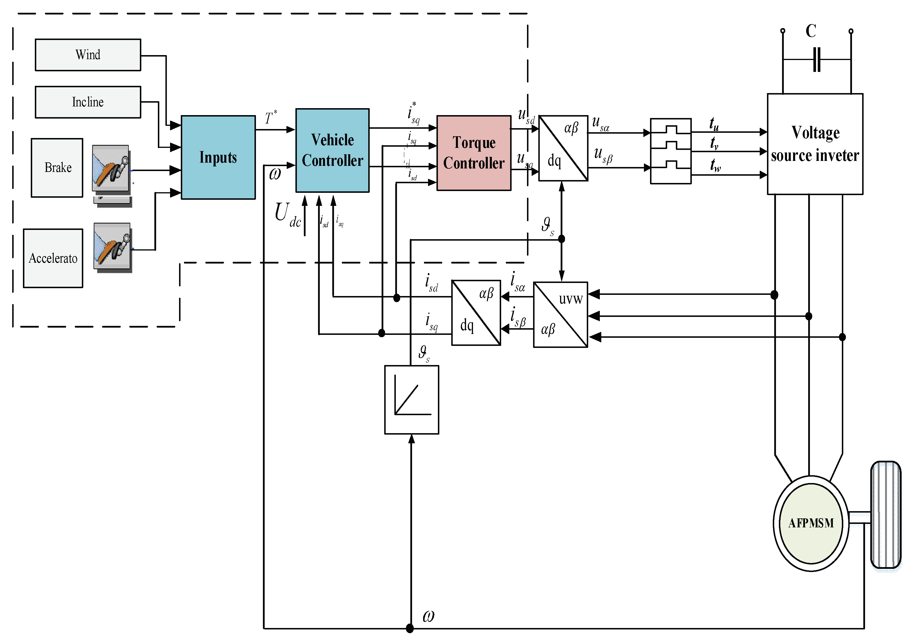
Figure 8.
Current responses , for PI controller.
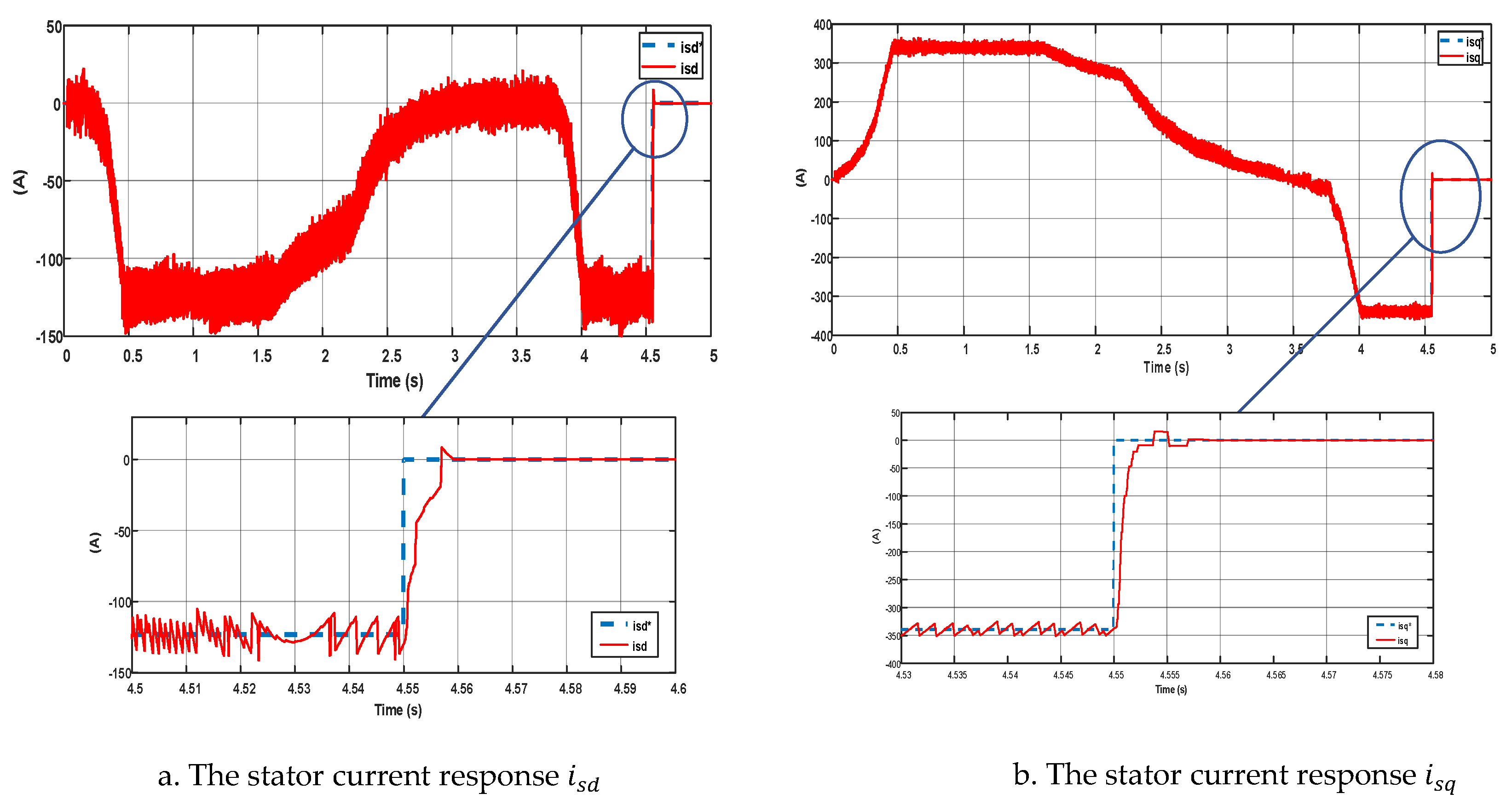
Figure 9.
Current responses , for FLC controller.

Figure 10.
Current responses , for FLC controller.
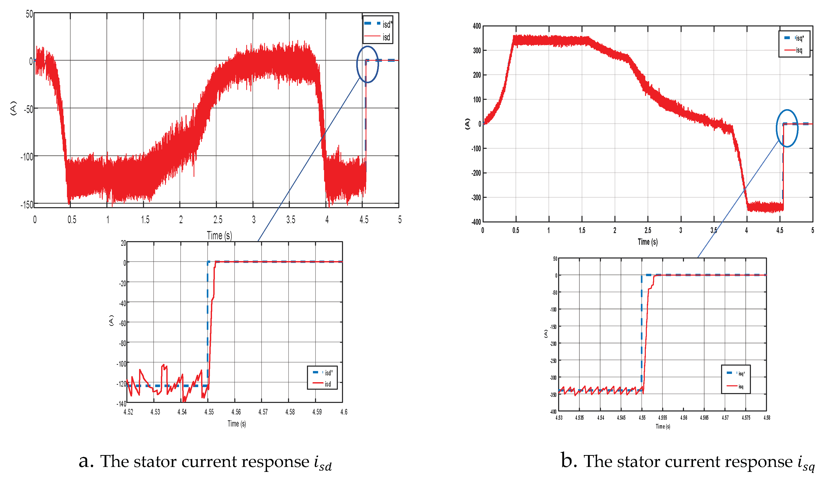
Figure 11.
Torque responses for PI controller.
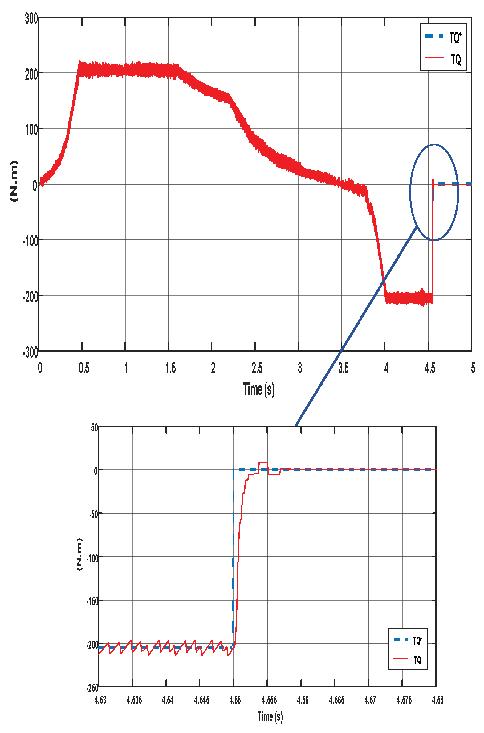
Figure 12.
Torque responses for FLC controller.
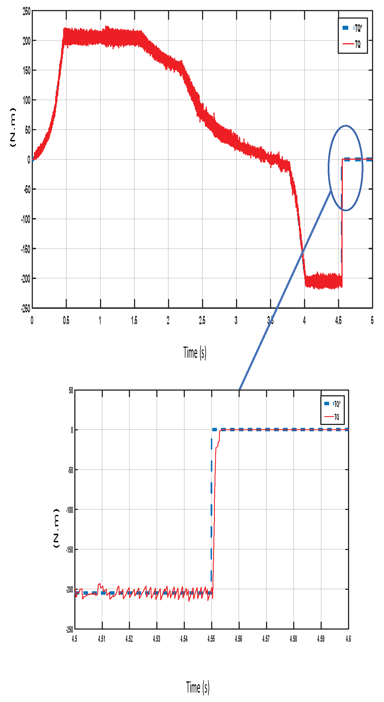
Figure 13.
Torque responses for NFC controller.
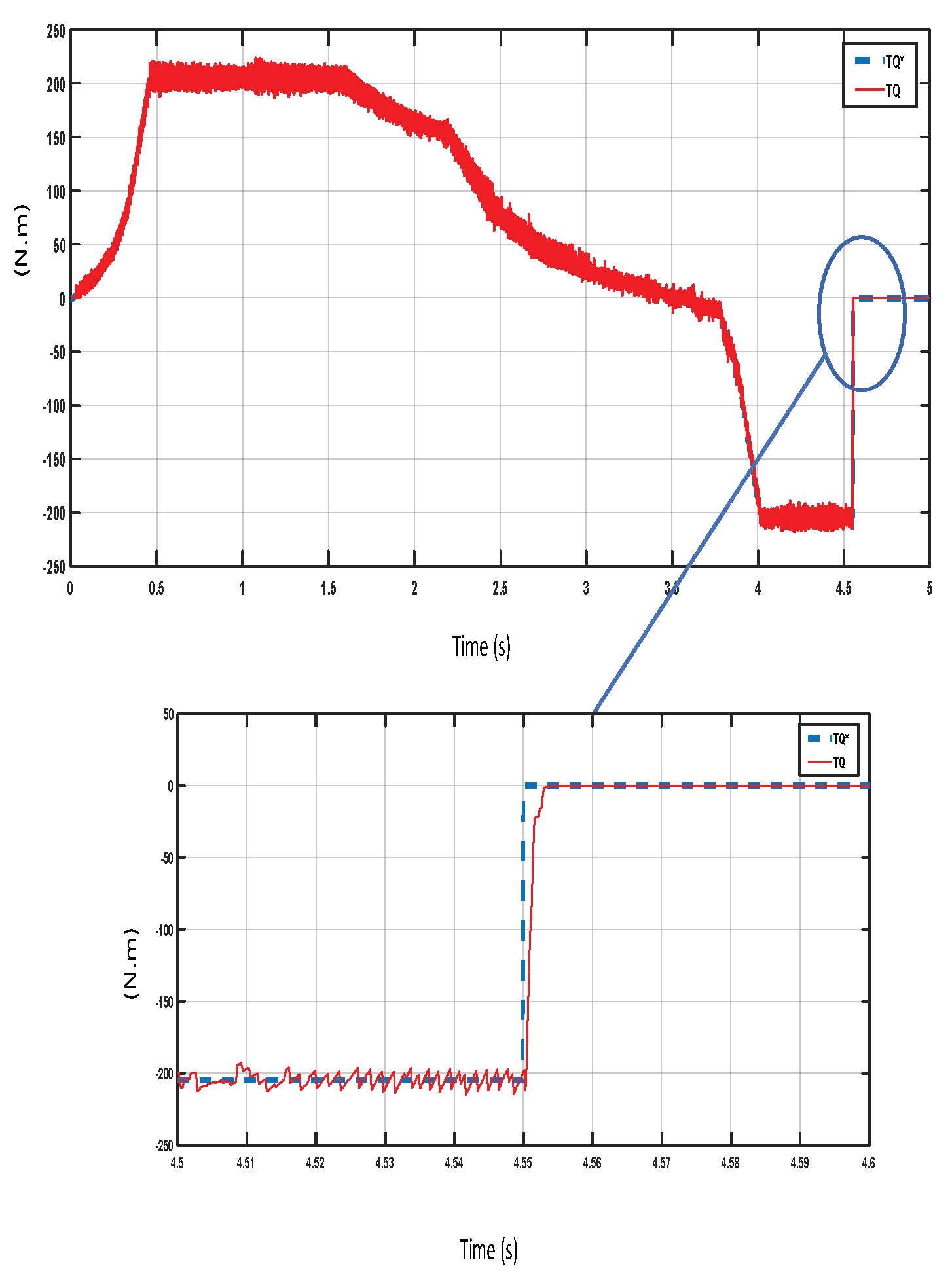
Figure 14.
Speed responses for PI, FLC and NFC controller.
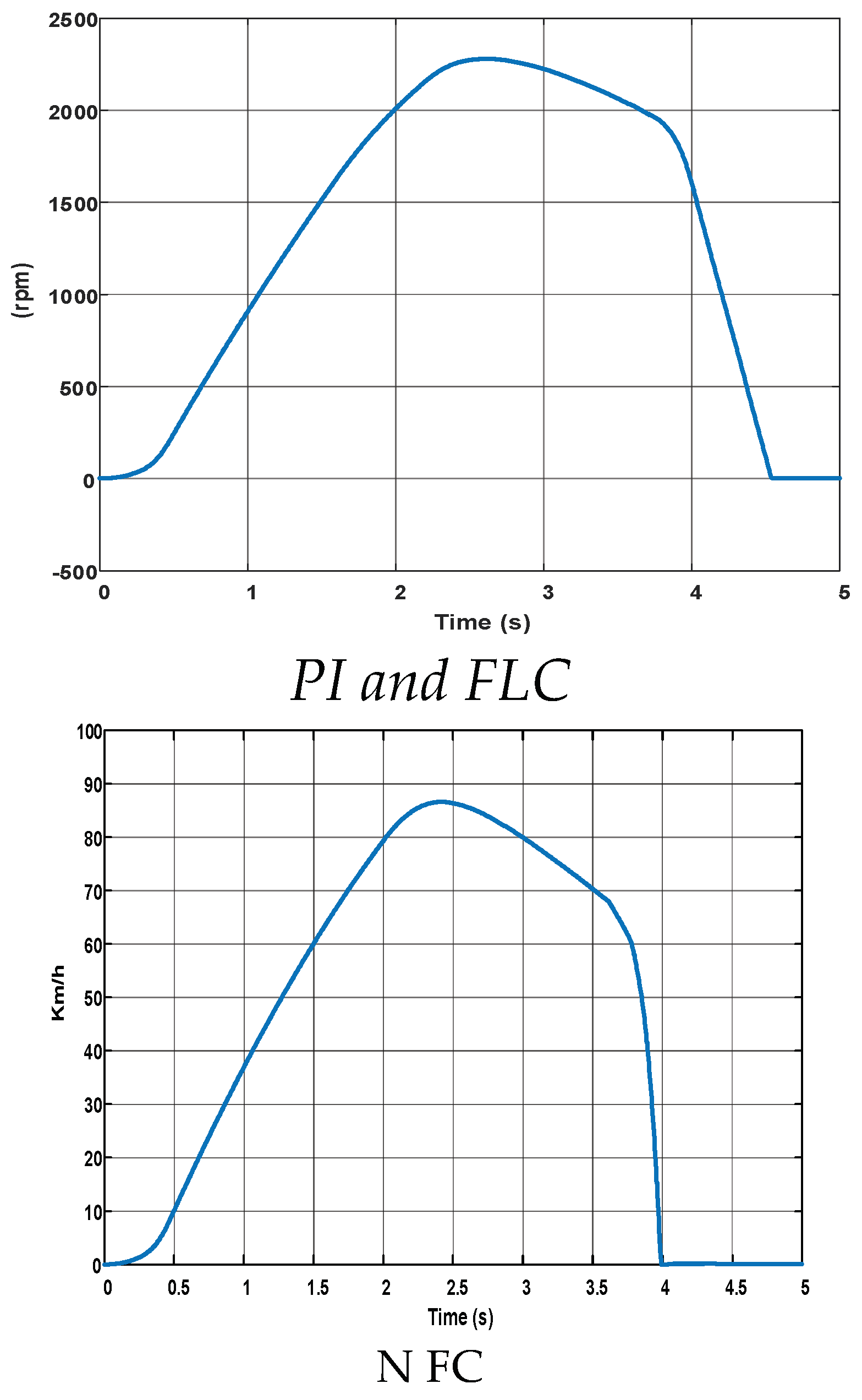
Figure 15.
Stator curent responses for PI controller when changing parameters Ld, Lq by 20%.
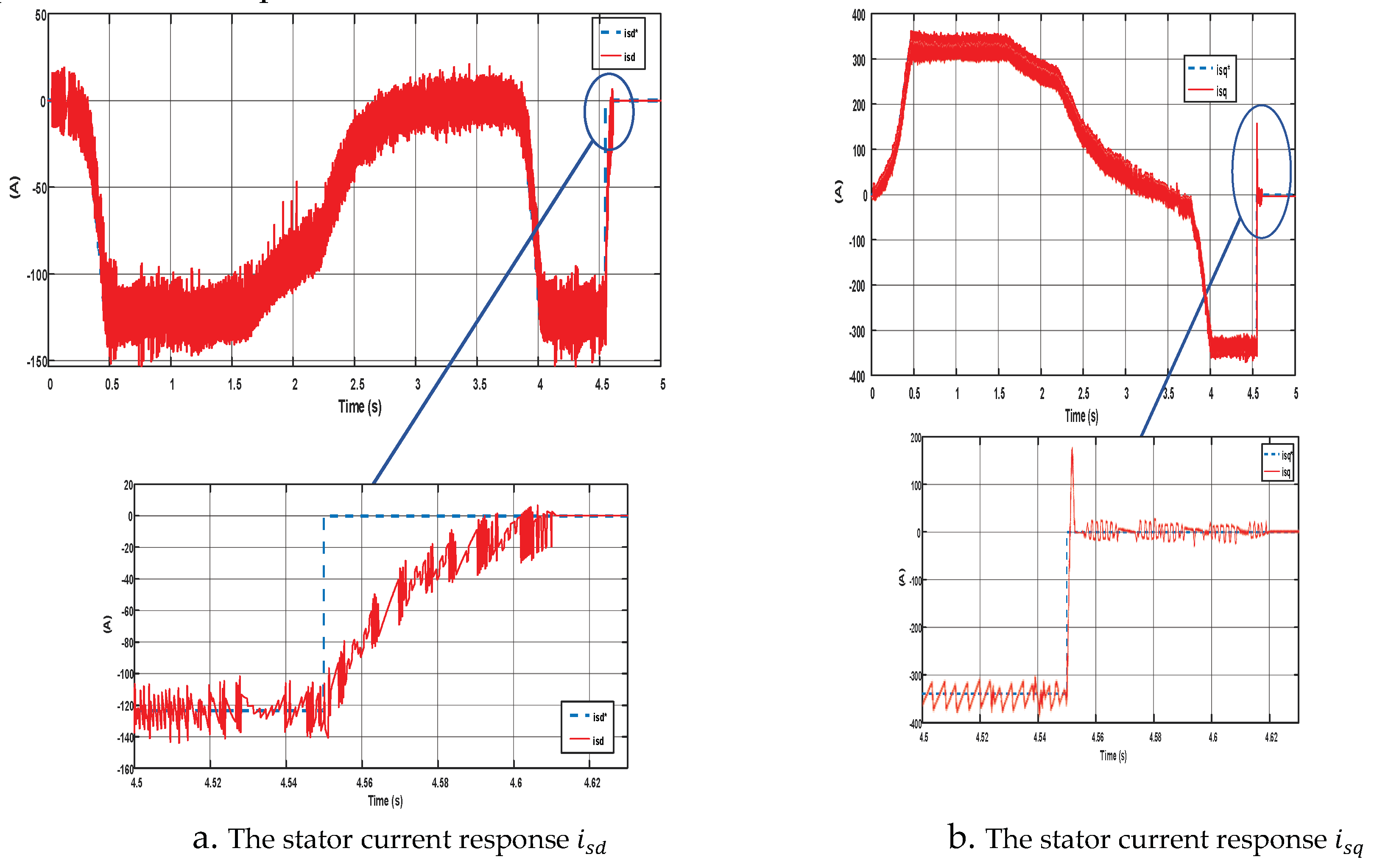
Figure 16.
Stator curent responses for FLC controller when changing parameters Ld, Lq by 20%.

Figure 17.
Stator curent responses for FLC controller when changing parameters Ld, Lq by 20%.
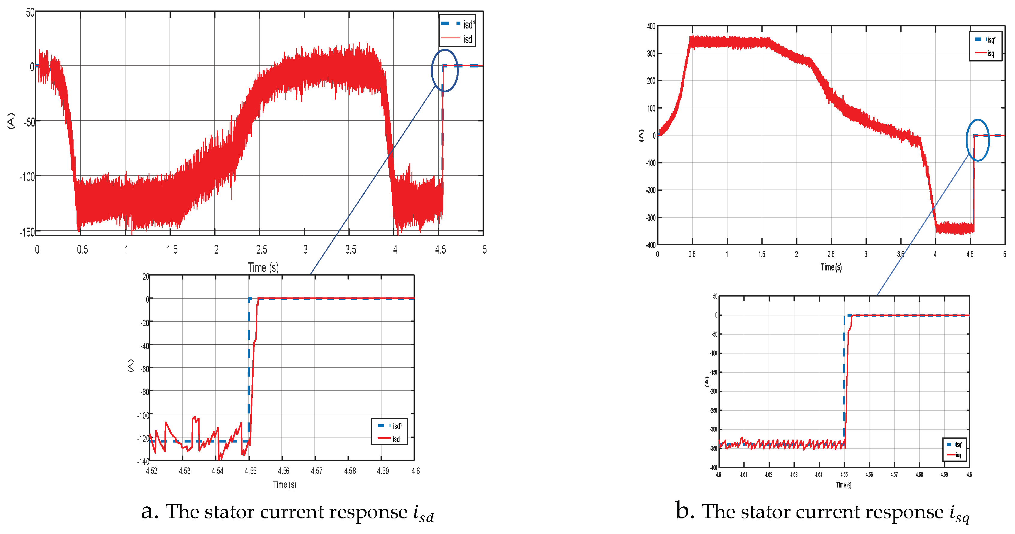
Figure 18.
Torque responses for PI controller when changing parameters Ld, Lq by 20%.
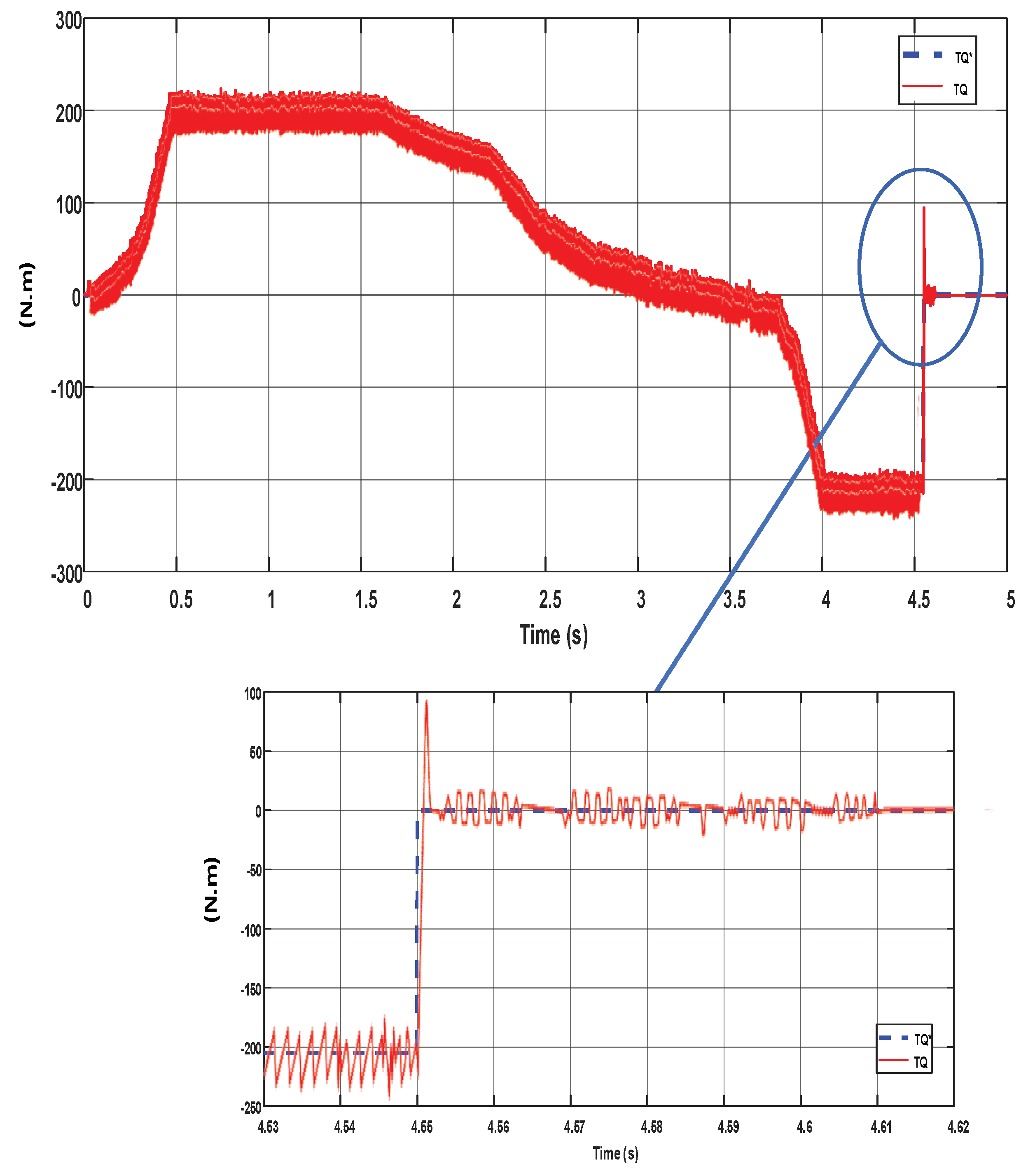
Figure 19.
Torque responses for FLC controller when changing parameters Ld, Lq by 20%.
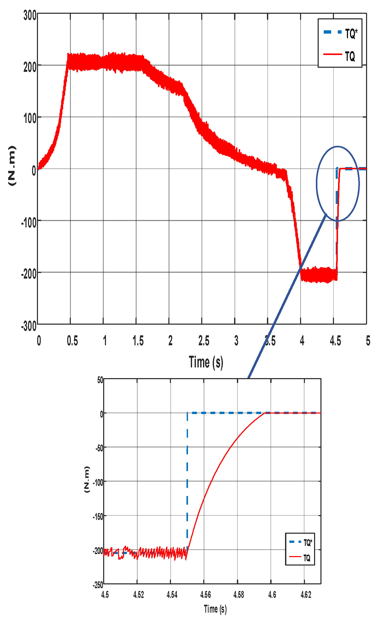
Figure 20.
Torque responses for NFC controller when changing parameters Ld, Lq by 20%.
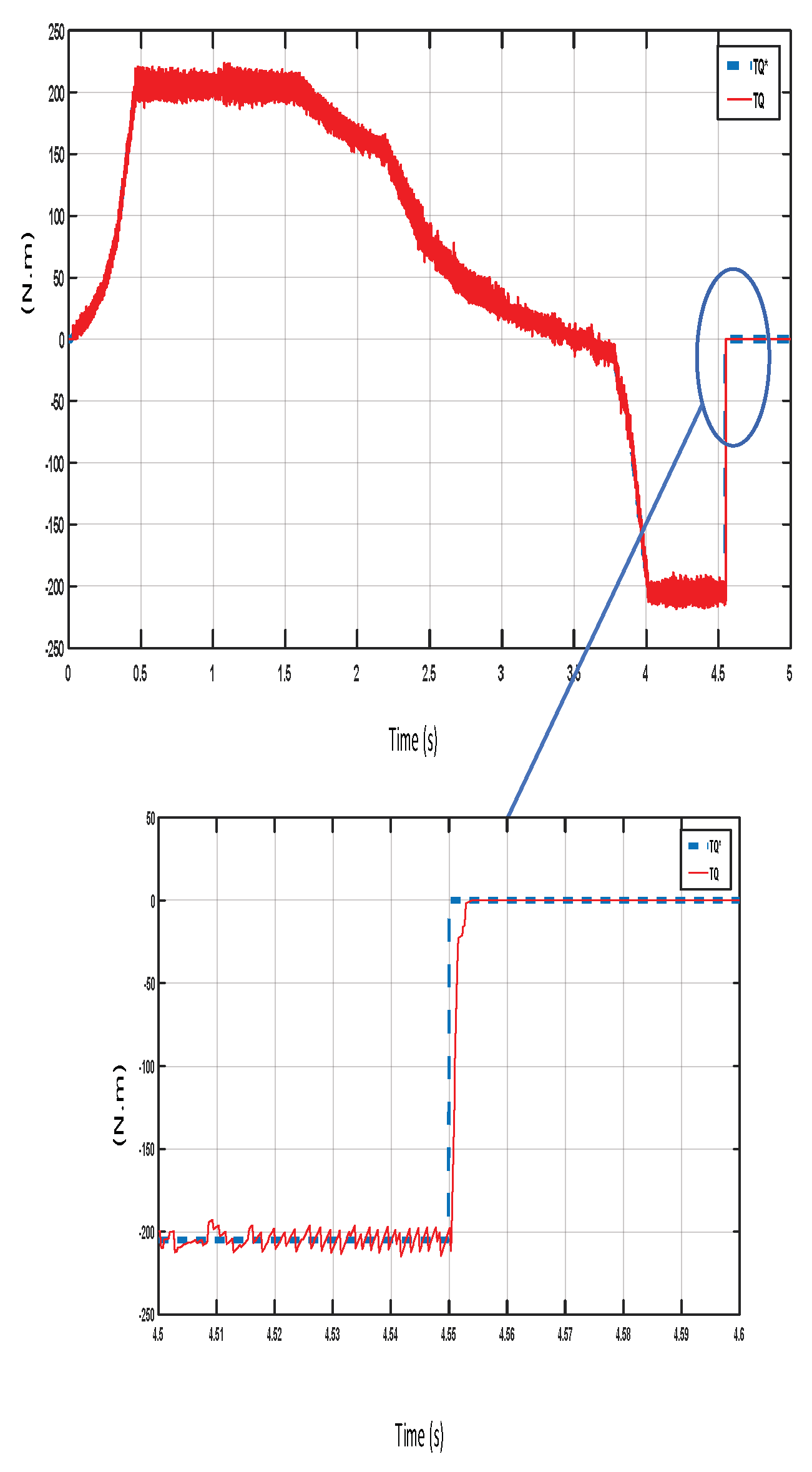

Table 1.
Matrix of controller.
| Input 1 (e) | NB | NS | ZE | PS | PB | |
|---|---|---|---|---|---|---|
| ) | ||||||
| NB | NB | NB | NB | NS | ZE | |
| NS | NB | NB | NS | ZE | PS | |
| ZE | NS | NS | ZE | PS | PB | |
| PS | ZE | ZE | PS | PB | PB | |
| PB | ZE | PS | PB | PB | PB | |
Table 2.
Parameters for an AFPMSM motor.
| Motor parameters | Value Symbol | Value Symbol |
|---|---|---|
| Power | Pđm | 35 kw |
| Rated speed | Nđm | 1800 rpm |
| Rated voltage | Uđm | 275V |
| Number of pole pairs | Zp | 8 |
| Magnetic flux density | 0.0437 | |
| Maximum torque | Pmax | 205Nm |
| Armature resistance | Rs | 0.0101 |
| Shaft inductance d | Ld | 2.4368e-4 H |
| Shaft inductance q | Lq | 2.9758e-4 H |
Table 3.
Parameters for an AFPMSM motor.
| Controller | Ki | Kp |
|---|---|---|
| Current controller Id | 7.103004e+2 | 0.8779 |
| Current controller Iq | 1.0615e+3 | 1.0744 |
Table 4.
Results of evaluation responsibility.
| Controller/Parameter evaluation PI | PI | FLC | NFC |
|---|---|---|---|
| Stator current isd | |||
| Accelerated setting time | 0.4 (s) | 0.4 (s) | 0.4 (s) |
| Over-adjustment | 10% | 0% | 0% |
| Stator current isq | |||
| Set-up time | 0.4 (s) | 0.4 (s) | 0.4 (s) |
| Over-adjustment | 10% | 0% | 0% |
Table 5.
Results of evaluation responsibility.
| Controller/Parameter evaluation PI | PI | FLC | NFC |
|---|---|---|---|
| Torque responses | |||
| Shape | Same as isq current response |
Same as isq current response | Same as isq current response |
| Torque ripple | 8% | 5% | 3% |
| Speed responses | |||
| Accelerated setting time | 2.2 (s) | 2.2 (s) | 2.2 (s) |
| Over-adjustment | 0% | 0% | 0% |
Table 6.
Results of evaluation responsibility.
| Controller/Parameter evaluation PI | PI | FLC | NFC |
|---|---|---|---|
| Stator current isd | |||
| Accelerated setting time | 0.5 (s) | 0.5 (s) | 0.5 (s) |
| Over-adjustment | 10% | 5% | 0% |
| Stator current isq | |||
| Set-up time | 0.5 (s) | 0.5 (s) | 0.5 (s) |
| Over-adjustment | 20% | 5% | 0% |
Table 7.
Results of evaluation responsibility.
| Controller/Parameter evaluation PI | PI | FLC | NFC | |
|---|---|---|---|---|
| Torque responses | ||||
| Shape | Same as isq current response | Same as isq current response | Same as isq current response | |
| Torque ripple | 30% | 16% | 5% | |
| Speed responses | ||||
| Accelerated setting time | 2.2 (s) | 2.2 (s) | 2.2 (s) | |
| Over-adjustment | 20% | 0% | 0% | |
Disclaimer/Publisher’s Note: The statements, opinions and data contained in all publications are solely those of the individual author(s) and contributor(s) and not of MDPI and/or the editor(s). MDPI and/or the editor(s) disclaim responsibility for any injury to people or property resulting from any ideas, methods, instructions or products referred to in the content. |
© 2023 by the authors. Licensee MDPI, Basel, Switzerland. This article is an open access article distributed under the terms and conditions of the Creative Commons Attribution (CC BY) license (http://creativecommons.org/licenses/by/4.0/).
Copyright: This open access article is published under a Creative Commons CC BY 4.0 license, which permit the free download, distribution, and reuse, provided that the author and preprint are cited in any reuse.


