1. Introduction
Heating and cooling demands in the European Union (EU) in 2020 accounted for 50% of the total gross final energy consumption [
1]. The energy efficiency of a building is primarily influenced by two key components: the building envelope and the air-conditioning system [
2]. The increase in cooling degree days value from 37 in 1979 to 100 in 2021 suggests that the demand for cooling, particularly air conditioning, has indeed increased in EU over the past few decades [
3]. Heatwaves are becoming more frequent and intense, particularly in southern and central European countries the temperature reaches a record high 40°C in resent summertime [
4]. The use of air conditioners and electric fans for cooling purposes account for a significant portion of electricity consumption in buildings worldwide. According to International Energy Agency (IEA) reports, cooling-related energy consumption in buildings can contribute to approximately 20% of total electricity usage [
5]. The energy demand for cooling in the EU is continuously increasing because an inappropriate indoor climate can cause observable problems for people and is mainly related to reduced productivity and negative health impacts [
6]. This high level of energy consumption for cooling is one of today's biggest challenges due to environmental, economic, social and security factors, which means that there is an extremely urgent need to find smart, sustainable, and inclusive cooling systems technologies for the EU to be climate neutral by 2050. According to a European Environment Agency (EEA) report [
7] cooling technologies are mostly powered by fossil fuels.
In recent years, there has been a growing interest in cooling absorption systems due to policies aimed at reducing CO
2 emissions. Absorption systems, particularly those equipped with absorption chillers for cooling applications, can indeed play a significant role in working towards climate neutrality due to their low electricity consumption, making them more energy-efficient compared to traditional vapor compression systems [
8]. The H
2O/LiBr absorption system is notable for its use of water as the coolant, which offers an environmentally friendly advantage [
9]. Additionally, the heat source for the H
2O/LiBr absorption system can be solar heated water, further enhancing its environmental benefits. At present, ensuring energy independence by using renewable energy sources (RES) and improving energy efficiency have emerged as critical subjects demanding immediate attention and focused efforts [
10] Solar energy is considered one of the cleanest and most abundant energy sources available worldwide. However, one limitation of solar energy is its intermittent nature. This intermittency can pose challenges for continuous and consistent energy supply. To overcome this limitation and ensure continuous operation of the load, energy storage technologies are used. Storage for solar electricity is already a well-developed technology that has been widely used, while thermal energy storage for solar heat is currently undergoing research and development, suggesting that it has not yet reached a mature stage [
11]. The existing body of literature regarding thermal energy storage can be categorized according to the type of heat stored, such as sensible heat storage or latent heat storage (LHS) [
12]. Phase change materials (PCMs) are regarded as promising energy-saving materials due to their ability to store and release significant amounts of latent heat during isothermal phase transitions, this quality makes them suitable for delivering efficient heating or cooling energy [
13,
14]. The use of PCM in latent heat thermal energy storage (LHTES) enables high energy storage density while maintaining a relatively stable operating temperature [
15,
16]. LHTES technology holds significant value in various renewable energy applications, including electricity "peak shaving" and promoting energy efficiency in industrial and civil buildings, among other areas [
17,
18]. The LHTES integration into the existing solar cooling system can reduce the energy consumption and to increase the system coefficient of performance (COP) [
19,
20]
The study is based on previous authors studies [
21,
22,
23,
24] the main aim of the this work is to improve the efficiency of latent heat thermal energy storage (LHTES) by proposing the different PCM tank configuration. The research was based on a dynamic simulation of a system in TRNSYS 18 software. The paper is organized as follows: firstly, the Materials and Methods section starts from the description of system and system model is presented. Secondly, the Results section presents the 10-day model simulation results in TRNSYS. Thirdly, the Conclusions section, based on the obtained results from simulations.
2. Materials and Methods
2.1. Description of the System and System Model
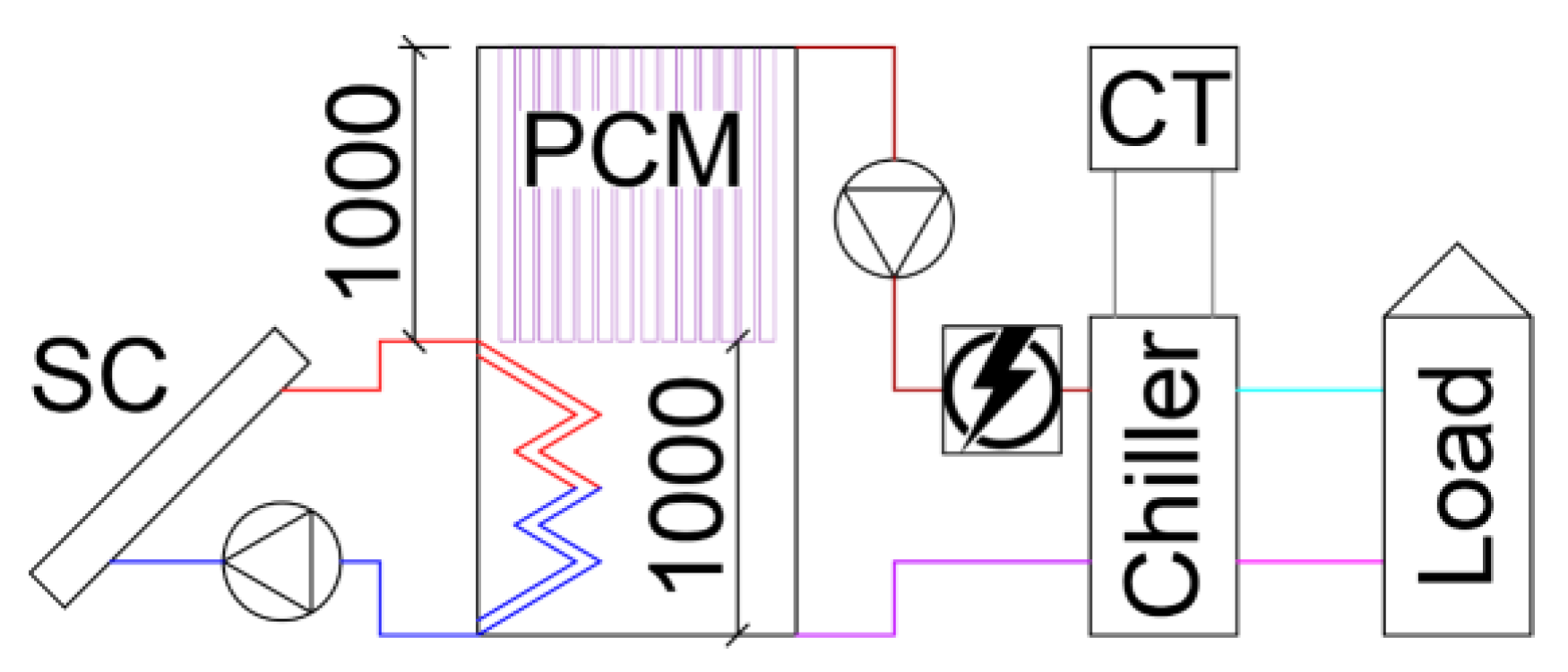
In order to investigate the effect of PCM on the temperature stability of the tank, which is particularly important for the operation of the absorption cooling system, a model was developed in TRNSYS and validated with the real system. The research focuses on optimizing energy storage by integrating containers with phase change materials, which can decrease the consumption of auxiliary heater energy and increase the coefficient of performance (COP) of the solar cooling system. The study also aims to reduce the environmental impact of the cooling system. The system studied in this research consists of vacuum solar collectors (SC) connected via a heat exchanger to a 1 m
3 heat storage tank containing PCM in the top part of the tank (see
Figure 1). The system utilizes water from the tank as a heat source for an absorption chiller with cooling tower (CT). In cases where the water temperature is insufficiently high, an auxiliary electric heater is used to raise the temperature of the water before chiller.
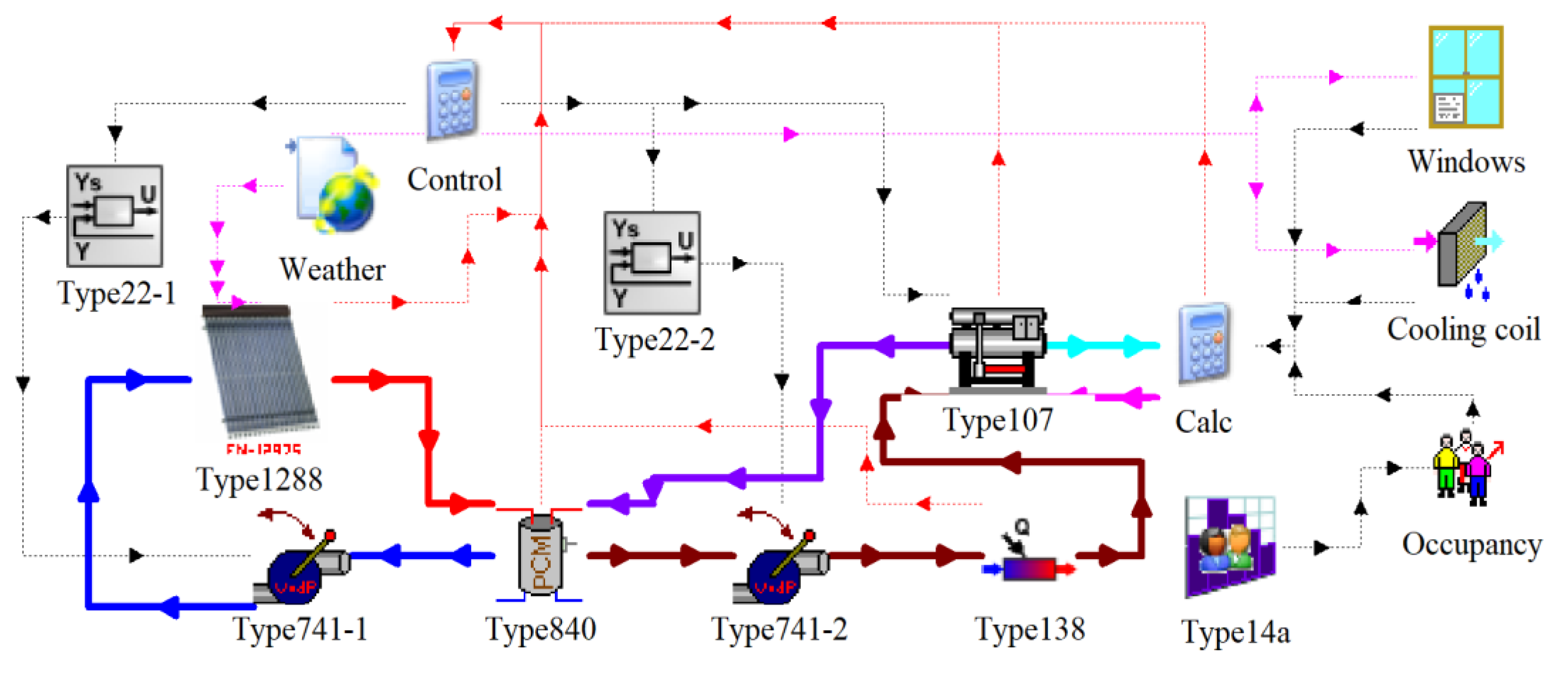
The research was based on a dynamic simulation of a system (see
Figure 2). The system model was created using the TRNSYS 18 software, and various scenarios were explored by varying the amount of phase change materials in the tank, the number of installed vacuum solar collectors, the cooling loads and auxiliary heater temperature setpoint.
2.2. System Model Components
2.2.1. Vacuum Solar Collector
Vacuum solar collector (Type1288) area (total) = 28 m2; efficiency = 0.568; α1 = 1.04 W/m2K; α2 = 0.0024 W/m2K2; heat capacity = 6.5 kJ/m2K. The inclination of solar collectors: 45°; south direction. At the ambient air temperature of +25 °C, mean heat carrier temperature in collector +90 °C, and solar radiation on the surface of 1000 W/m2, the simulated solar plant (28 m2) may produce 13.7 kW of heating energy.
2.2.2. PCM Tank
PCM tank (Type840) created by [
25]. Volume 1000 L, height 2 m, insulated with 100 mm mineral wool, the total heat loss rate is determined by formula (2.26 * ΔT + 0.0072 * ΔT
2), where ΔT is the temperature difference between average tank temperature and outside air temperature. Water specific heat capacity 4.2 kJ/kgK and density 970 kg/m
3, effective vertical thermal conductivity 2 W/mK.
PCM container properties: outer diameter: 54 mm, thickness: 1.5 mm, length: 1 m, thermal conductivity: 395 W/mK, specific heat capacity: 0.38 kJ/kgK, density: 8900 kg/m3.
Based on the material properties and average cost, it was decided to use commercially available material RT90HC. PCM properties: specific heat capacity: 2 kJ/kgK, phase change enthalpy: 170 kJ/kg, temperature at the start of phase change: 91 °C, at the end of phase change: 92 °C, temperature difference (hysteresis) between the melting and solidification curves: 1 °C, density of the PCM material: 850 kg/m3, thermal conductivity material: 0.2 W/mK.
It is geometrically possible to install 154 PCM containers (see
Figure 3), that results in 35.3% of volume of the tank. Additionally, cases with 52 (11.9%), 80 (18.3%) and 114 (26.1%) PCM container were investigated.
2.2.3. Circulation Pump
Circulation pump (Type 741-1 and Type 741-2): overall pump efficiency 0.6, motor efficiency 0.9, pressure drop 50 kPa, motor is mounted within the fluid stream. Pump is controlled by Iterative feedback controller (Type 22-1 and Type 22-2) to provide 5°C heat carrier temperature difference between supply and return pipes of solar collector loop and 10°C heat carrier temperature difference between supply and return pipes of chiller loop.
2.2.4. Auxiliary Fluid Heater
Auxiliary Fluid Heater (Type138): efficiency 100% (electrical heater).
2.2.5. Absorption Chiller
Solar energy is generated by a system of solar thermal collectors and stored in a thermal energy storage tank. The hot heat carrier from the thermal energy storage is fed to the generator to boil the water vapour from the H
2O/LiBr solution. The resulting water vapor is then cooled in a condenser before being directed to an evaporator. In the evaporator, the vapor is further cooled and evaporated under lower pressure and temperature conditions. The solution leaving the generator and flowing to the absorber passes through a solution heat exchanger to preheat the weak solution stream entering the generator. In the absorber, the solution absorbs the water vapour flowing from the absorber to the evaporator. An additional heater is provided to raise the temperature of the hot water supplied, if this is not sufficient to operate the generator, the heat transfer medium is heated to the required temperature for the generator. The main advantage of absorption systems is that the amount of electricity to run the system is limited to the solution pump, which, compared to vapor compression systems, does not consume as much electricity for compression. When comparing absorption cycle COP (0.5 to 0.8) [
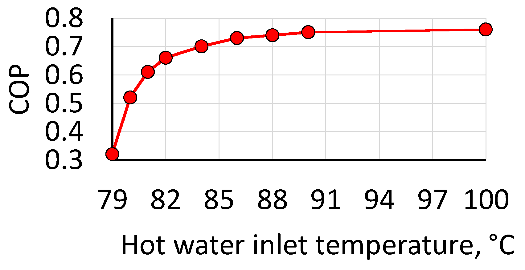
26] to traditional cooling systems, the absorption cycle efficiency optimization becomes significant. Hot Water-Fired Single-Effect Absorption Chiller (Type107): COP is defined by external file according to
Figure 4. Cooling tower is not presented in model. It is assumed that cooling water inlet temperature is 30 °C and flowrate 3000 kg/h. Chilled water setpoint 7 °C.
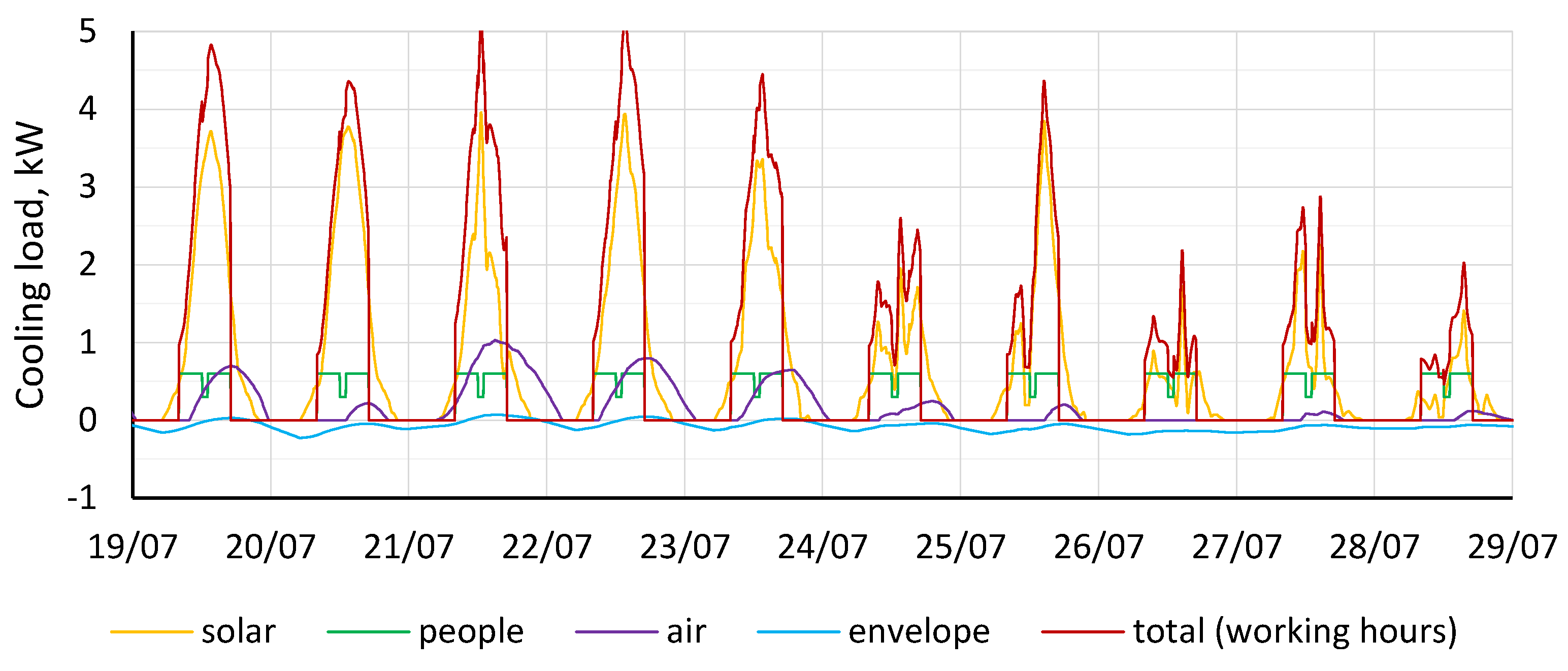
2.2.6. Base load
Base load (see
Figure 5) is calculated dynamically based on sum of:
Solar heat gain from windows (Type 687): total area 12 m2, solar heat gain coefficient 0.6, vertical surface facing south;
Occupancy (Type 574): activity level - seated, light work, typing. Schedule defined by (Type 14a): 4 people from 8:00 till 12:00, 2 people from 12:00 till 13:00 and 4 people from 13:00 till 17:00;
Ventilation air cooling coil (Type 752) with dry air flowrate 300 kg/h and temperature setpoint 18 °C;
Envelope: window loss coefficient 1.1 W/m2.
Chiller is operated by total cooling load only during working hours (8:00 – 17:00).
2.2.7. Climate Data, Simulated Period and Variables
Climate data: Meteonorm\Europe\LV-Riga.tm2.
Simulated period: July 18 – July 29. The simulation timestep 60 s. The first day is not used in the analysis, as it is simulated to determine the initial conditions in the tank. 5 days are sunny, 5 days are cloudy.
Variables:
P – number of PCM modules (0 / 52 / 80 / 114 / 154);
L – fraction of base load (0.5 / 1 / 1.5 / 2);
S – area [m2] of solar collectors (12 / 20 / 28 / 36 / 44;)
T – auxiliary heater temperature setpoint [°C].
3. Results
The results presented in this study are based on a 10-day simulation in TRNSYS. The electricity consumption of the auxiliary heater was used as the primary parameter to evaluate the efficiency of the system across various scenarios.
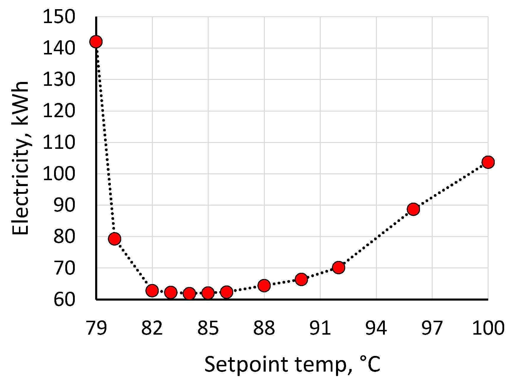
Initially, the optimal setpoint temperature for the auxiliary heater was determined. According to
Figure 6, this was found to be between 83°C and 85°C. Operating the system with a lower setpoint resulted in a lower COP of the chiller, as shown in
Figure 4. However, setting the setpoint higher led to an increase in electricity consumption due to a reduction in tank heat storage capacity and an increase in heat losses. Consequently, a setpoint of 84°C was used for further calculations.
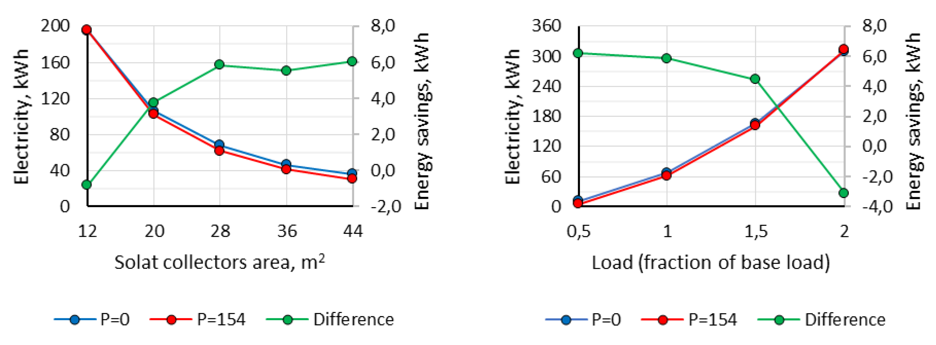
The impact of solar collector area on the performance of the system was studied, as shown in
Figure 7 (left), under two scenarios: one without PCM in the storage tank, and another with 154 PCM modules. When the solar collector area was small (12 m
2), the use of PCM led to a 0.4% increase in electricity consumption. This can be attributed to the fact that the temperature inside the storage tank was mostly below the PCM melting temperature, resulting in a decrease in the total storage capacity due to the lower specific heat capacity of the PCM (2 kJ/kgK) compared to water (4.2 kJ/kgK). However, as the solar collector area was increased, the electricity consumption decreased, and the impact of the PCM became more significant. The energy savings achieved through the use of PCM peaked at a solar collector area of 28 m
2, resulting in a reduction of 6 kWh, which remained relatively stable with further increases in collector area. A solar collector area of 28 m
2 was used for further calculations.
The next task was to assess the effect of cooling loads on the system's performance by varying the base load (
Figure 5) by a factor of 0.5, 1.5, and 2. The findings are illustrated in
Figure 7 (right). The use of PCM was found to have the most pronounced influence at lower cooling loads, while excessively high cooling loads resulted in a 1.0% increase in auxiliary heater electricity consumption, similarly as it happened in case with low numbers of installed solar collectors. Thus, a proper design of the number of collectors based on actual cooling load is essential to optimize system performance.
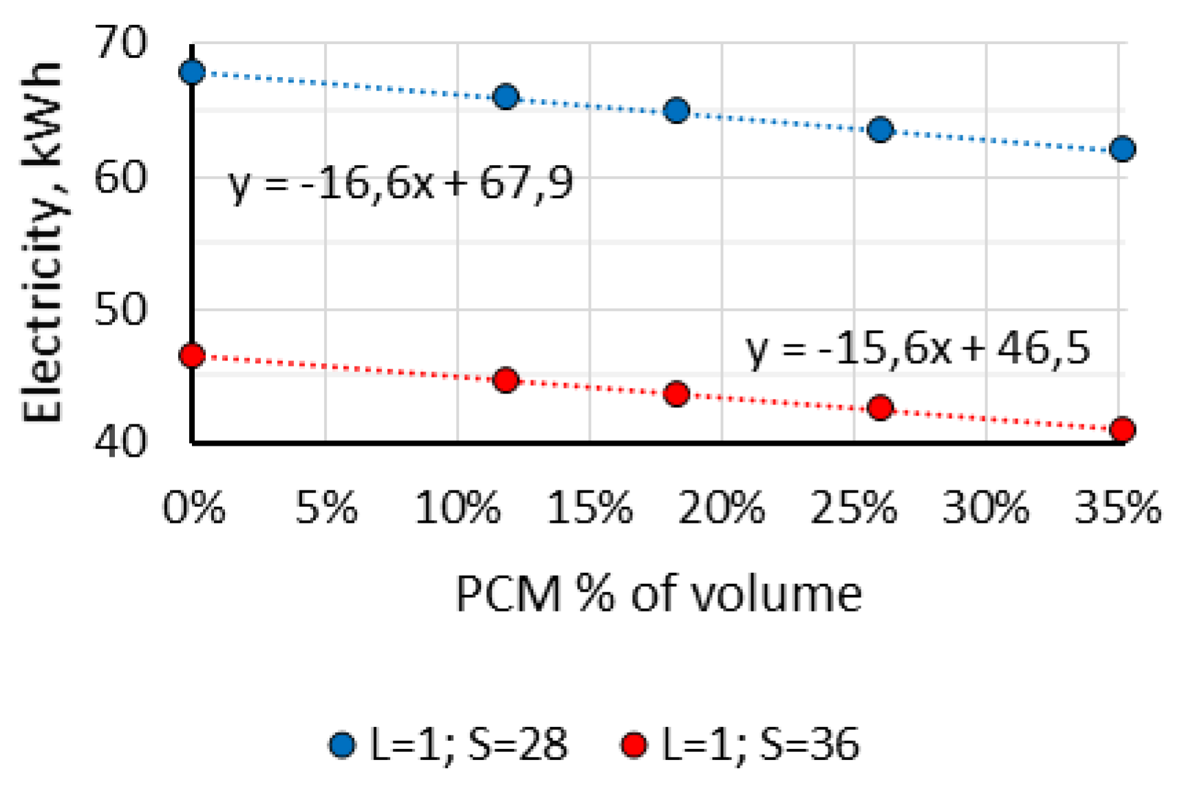
The regression analysis revealed a linear relationship between the volume of PCM and electricity consumption (see
Figure 8).
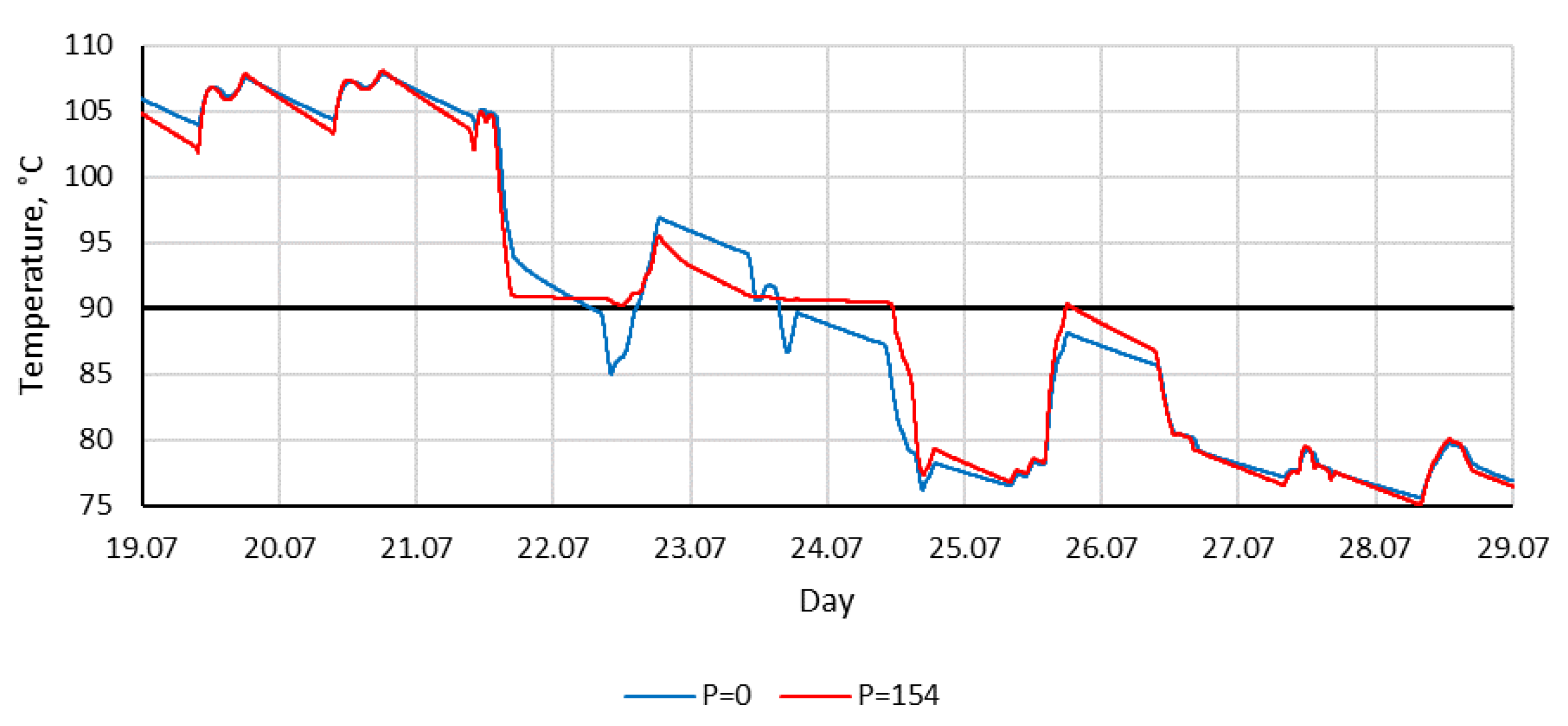
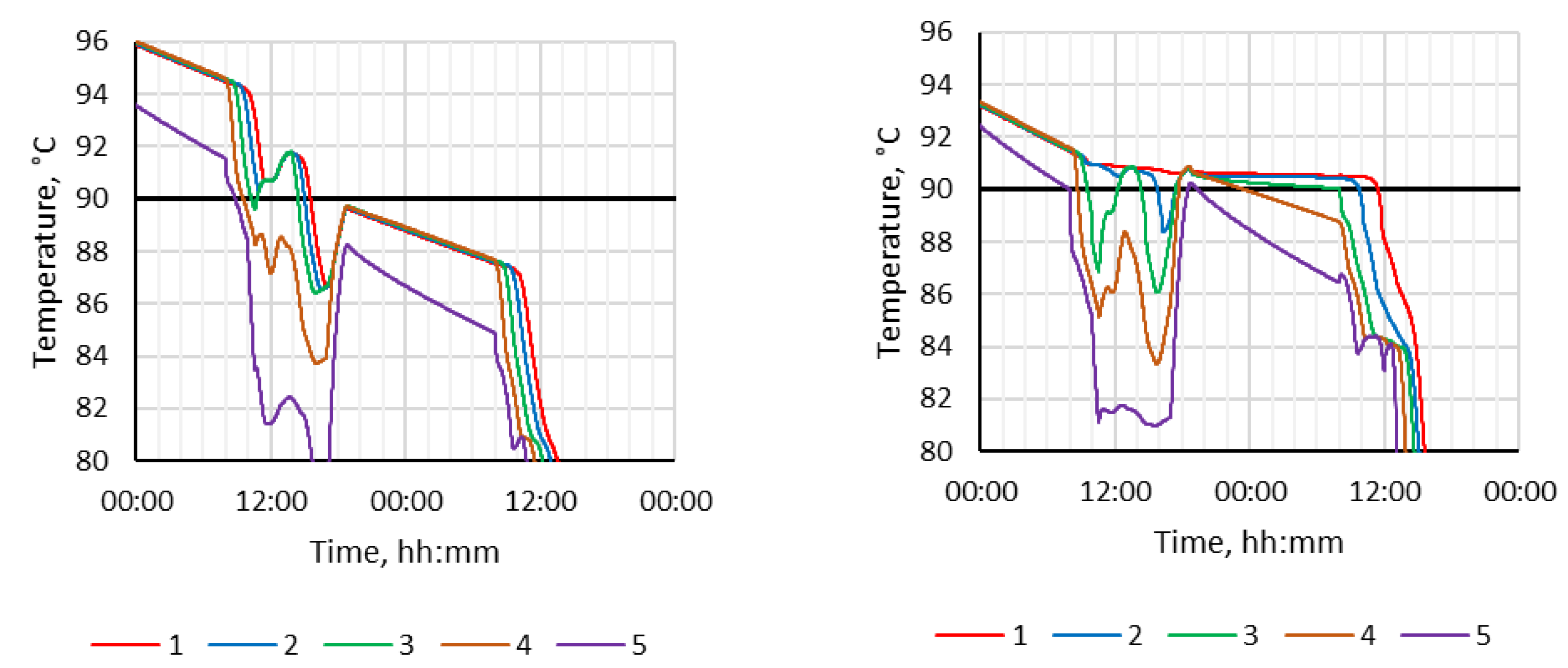
Figure 9 illustrates the heat carrier temperature from the storage tank to the auxiliary heater. During periods with sufficient solar energy (19.07 – 21.07), the heat carrier temperature was slightly lower in the case with PCM modules compared to the case without PCM, resulting in lower heating energy losses in the tank. The main impact of PCM was observed when the weather changed (24.07) and the total cooling load exceeded the amount of produced solar energy. This observation confirms that the PCM effect is significant under fluctuating conditions. Despite this, the heat carrier temperature remained above 90°C for a longer period of time, resulting in lower electricity usage by the auxiliary heater, as shown in
Table 1.
Figure 10 shows the temperature profile inside the storage tank with a 0.5 m vertical step, where 1 represents the top and 5 represents the bottom of the tank.
4. Discussion
Additionally, two simulation cases (P0, L1, S28, T84 and P154, L1, S28, T84) were evaluated for the period between 31.05 and 31.08, with the initial conditions in the tank determined from a simulation of 31.05 (which was excluded from the analysis). During the summer months, the TRNSYS simulation results indicate that 2766 kWh of solar energy was produced, out of which 14.7% was lost as heat from the storage tank. The cooling load was 1945 kWh, and the electricity consumption of the two circulation pumps was 18 kWh. The auxiliary heater electricity consumption was 776 kWh without PCM, while it was 727 kWh with 154 PCM modules. The use of PCM resulted in a 6.2% reduction in auxiliary energy consumption. Moreover, the period of time with heat carrier temperature flow from the storage tank to the auxiliary heater exceeding 90°C was 27.8% longer with the use of PCM in comparison to without it.
This work is dedicated only to the design of possible LHTES construction for solar cooling system optimization the economic issues of system are outside of the scope of this work. Although studies show that some LHTES not only increase the efficiency of the system, but also have a relatively low cost [
28], [
29] The main drawback of this work is the inability to determine the profitability of the proposed system at the moment, as only a system prototype was developed for the time being. However, this aspect will be considered in our next work, when the system prototype will be tested in real conditions.
5. Conclusions
The developed LHTES construction for solar cooling system was successfully validated in laboratory conditions through experimental data collected during a measurement analysis carried out at the Riga Technical University (RTU) in the framework of project “Latent heat storage for sustainable cooling”.
This paper presents and examines the simulation outcomes achieved by this model across different LHTES PCM tank construction – PCM placement in the tank, providing detailed analysis and discussion of the findings. The results are used to optimize the operation of the solar cooling system by integrating LHTES into it. More specifically, the considered solar cooling system with LHTES is simulated for air conditioning for the needs of a small office in Latvia, Riga. Using experimental data from the solar cooling system laboratory prototype developed by RTU.
As a result of the research, it was concluded that such design LHTES optimization approach (the main effect of PCM) was observed when the weather changed, and the total cooling load exceeded the amount of solar energy produced. Changes in weather conditions for Latvia's climate are common due to the influence of the Baltic Sea, which only proves that the proposed LHTES optimization approach can be useful and effective. It was observed that the beneficial effect of PCMs on the efficiency of LHTEs was on days with variable weather conditions or fluctuating solar energy availability. The effect is less pronounced under prolonged sunny conditions as the temperature in the tank does not fluctuate but remains constant. The studied LHTES solution can be used not only in solar assisted absorption cooling systems, but also when the heat source is waste heat from various processes.
Author Contributions
Conceptualization, L.M. and K.L.; methodology, L.M.; software, R.B.; validation L.M. and R.B.; formal analysis, K.L.; investigation, L.M., R.B. and K.L.; data curation, L.M..; writing—original draft preparation, L.M.; writing—review and editing, L.M. and K.L.; visualization, R.B. All authors have read and agreed to the published version of the manuscript.
Funding
This research received no external funding.
Data Availability Statement
Not applicable.
Acknowledgments
This work has been supported by the European Regional Development Fund within the Activity 1.1.1.2 “Post-doctoral Research Aid” of the Specific Aid Objective 1.1.1 “To increase the research and innovative capacity of scientific institutions of Latvia and the ability to attract external financing, investing in human resources and infrastructure” of the Operational Programme “Growth and Employment” (No.1.1.1.2/VIAA/4/20/661).
Conflicts of Interest
The authors declare no conflict of interest.
References
- Additional data - Energy - Eurostat. Available online: https://ec.europa.eu/eurostat/web/energy/database/additional-data (accessed on 31 May 2023).
- Borodinecs, A.; Gaujena, B. The implementation of building envelopes with controlled thermal resistance. In Proceedings of the 10th International Conference on Healthy Buildings 2012, July 2012, Brisbane: International Society of Indoor Air Quality and Climate (ISIAQ); pp. 1715–1722.
- Heating of buildings decreasing, cooling increasing - Products Eurostat News - Eurostat. Available online: https://ec.europa.eu/eurostat/en/web/products-eurostat-news/-/ddn-20220531-1 (accessed on 31 May 2023).
- Cooling Europe: urgent but not yet low-carbon. Available online: https://www.energymonitor.ai/sectors/heating-cooling/europe-what-about-cooling/ (accessed on 31 May 2023).
- The Future of Cooling – Analysis - IEA. Available online: https://www.iea.org/reports/the-future-of-cooling (accessed on 31 May 2023).
- Staveckis, A.; Borodinecs, A. Impact of impinging jet ventilation on thermal comfort and indoor air quality in office buildings. Energy Build 2021, 235. [Google Scholar] [CrossRef]
- European Environment Agency’s home page. Available online: https://www.eea.europa.eu/en (accessed on 31 May 2023).
- Zheng, J.; Castro, J.; Oliva, A.; Oliet, C. Energy and exergy analysis of an absorption system with working pairs LiBr-H2O and Carrol-H2O at applications of cooling and heating. International Journal of Refrigeration 2021, 132, 156–171. [Google Scholar] [CrossRef]
- Blanco-Marigorta, A.M.; Marcos, J.D. Key issues on the exergetic analysis of H2O/LiBr absorption cooling systems. Case Studies in Thermal Engineering 2021, 28, 101568. [Google Scholar] [CrossRef]
- Krizmane, M.; Slihte, S.; Borodinecs, A. Key Criteria Across Existing Sustainable Building Rating Tools. Energy Procedia 2016, 96, 94–99. [Google Scholar] [CrossRef]
- Kwasi-Effah, C.C.; Ighodaro, O.; Egware, H.O.; Obanor, A.I. A novel empirical model for predicting the heat accumulation of a thermal energy storage medium for solar thermal applications. J Energy Storage 2022, 56, 105969. [Google Scholar] [CrossRef]
- Raut, D.; Kalamkar, V.R. A review on latent heat energy storage for solar thermal water-lithium bromide vapor absorption refrigeration system. Journal of Energy Storage 2022, 55. [Google Scholar] [CrossRef]
- Shi, J.; Qin, M.; Aftab, W.; Zou, R. Flexible phase change materials for thermal energy storage. Energy Storage Materials 2021, 41. [Google Scholar] [CrossRef]
- Szajding, A.; Kuta, M.; Cebo-Rudnicka, A.; Rywotycki, M. Analysis of work of a thermal energy storage with a phase change material (PCM) charged with electric heaters from a photovoltaic installation. International Communications in Heat and Mass Transfer 2023, 140, 106547. [Google Scholar] [CrossRef]
- Niu, F.; Ni, L.; Yao, Y.; Yu, Y.; Li, H. Performance and thermal charging/discharging features of a phase change material assisted heat pump system in heating mode. Appl Therm Eng 2013, 58. [Google Scholar] [CrossRef]
- Anita, A.N.; Ramachandran, S. Design analysis of heat exchanger for the solar water heating systems using phase change materials. Mater Today Proc 2021, 47, 4533–4537. [Google Scholar] [CrossRef]
- Li, J.; et al. Thermal performance of a plate-type latent heat thermal energy storage heat exchanger - An experimental investigation and simulation study. J Energy Storage 2023, 65, 107295. [Google Scholar] [CrossRef]
- Panchal, J.M.; Modi, K.V.; Patel, V.J. Development in multiple-phase change materials cascaded low-grade thermal energy storage applications: A review. Clean Eng Technol 2022, 8, 100465. [Google Scholar] [CrossRef]
- Çam, N.Y.; Alptekin, E.; Bilir, L.; Ezan, M.A. Thermal behavior of a solar-assisted latent heat thermal energy storage unit on the heating season under variable weather conditions. J Energy Storage 2022, 52, 104934. [Google Scholar] [CrossRef]
- Qv, D.; Ni, L.; Yao, Y.; Hu, W. Reliability verification of a solar–air source heat pump system with PCM energy storage in operating strategy transition. Renew Energy 2015, 84, 46–55. [Google Scholar] [CrossRef]
- Snegirjovs, A.; et al. Performance Evaluation of Photovoltaic Solar Air Conditioning. Latvian Journal of Physics and Technical Sciences 2016, 53. [Google Scholar] [CrossRef]
- Lebedeva, K.; Migla, L. Latent thermal energy storage for solar driven cooling systems. Engineering for Rural Development 2020. [Google Scholar] [CrossRef]
- Migla, L.; Lebedeva, K. A Review for Phase Change Materials in Solar Cooling Systems. In Proceedings of the 2021 10th International Conference on Power Science and Engineering (ICPSE), IEEE, October 2021; pp. 110–116. [Google Scholar] [CrossRef]
- Migla, L.; Lebedeva, K. Optimization model of solar cooling system with latent heat storage. Acta Polytech CTU Proc 2022, 38, 295–301. [Google Scholar] [CrossRef]
- Moser, C.; Heinz, A.; Schranzhofer, H. TRNSYS Type 840: Simulation model for PCM/water storage tanks (Version 3.0) (V3.0); Graz University of Technology: Graz, 2022. [Google Scholar]
- Eicker, U.; Pietruschka, D. Design and performance of solar powered absorption cooling systems in office buildings. Energy Build. [CrossRef]
- Ketfi, O.; Merzouk, M.; Merzouk, N.K.; El Metenani, S. Performance of a Single Effect Solar Absorption Cooling System (Libr-H2O). Energy Procedia 2015, 74, 130–138. [Google Scholar] [CrossRef]
- Ying, Q.; Wang, H.; Lichtfouse, E. Numerical simulation on thermal behavior of partially filled metal foam composite phase change materials. Appl Therm Eng 2023, 229, 120573. [Google Scholar] [CrossRef]
- Alhusseny, A.; Al-Zurfi, N.; Nasser, A.; Al-Fatlawi, A.; Aljanabi, M. Impact of using a PCM-metal foam composite on charging/discharging process of bundled-tube LHTES units. Int J Heat Mass Transf 2020, 150, 119320. [Google Scholar] [CrossRef]
|
Disclaimer/Publisher’s Note: The statements, opinions and data contained in all publications are solely those of the individual author(s) and contributor(s) and not of MDPI and/or the editor(s). MDPI and/or the editor(s) disclaim responsibility for any injury to people or property resulting from any ideas, methods, instructions or products referred to in the content. |
© 2023 by the authors. Licensee MDPI, Basel, Switzerland. This article is an open access article distributed under the terms and conditions of the Creative Commons Attribution (CC BY) license (http://creativecommons.org/licenses/by/4.0/).
