
Submitted:
01 June 2023
Posted:
02 June 2023
You are already at the latest version
Abstract
This paper presents a novel DQ-based multicarrier Pulse Width Modulation PWM for a single-phase, three-level PV-powered grid-connected F-type inverter. The main control objective in the proposed inverter is to regulate the grid current with low total harmonic distortion and load power components compensation. Despite the F-type inverter’s advanced advantages, there are only a few works addressing the control issue in the literature yet. The proposed control and switching methods aim to achieve both DC side voltage balance and lowest switching losses. The proposed scheme has been designed based on a modified multi-carrier PWM switching algorithm. Consequently, the proposed control method able to satisfy the requirements of DC side voltage balance and achieve lower switching losses. A further advantage of the proposed control and switching methods is that they retain the main advantage of the F-Type inverter, which is that only 25% of the power switches are exposed to full DC voltage. This is an important advantage since it reduces the overall cost of the inverter and improves its reliability. Overall, the proposed modified multi-carrier PWM switching algorithm appears to be a promising approach for controlling the F-Type inverter, offering improved performance and efficiency compared to other control methods. The theoretical model was verified through simulation using MATLAB/Simulink. According to the simulation results, the grid current and dc capacitor voltages are successfully managed in all operational situations.
Keywords:
DQ-based control
; F-type inverter
; PV-powered inverter
1. Introduction
The proliferation of electric vehicle charging stations and increase in non-linear loads can have negative impacts on the power system in the case where there is not an efficient power management. Non-linear loads can introduce harmonic distortions, which can affect the voltage and frequency of the power system [1]. Power quality is a critical aspect of power systems, and improving it is essential particularly in grids that contain nonlinear loads [2]. Nonlinear loads, such as electronic equipment, cause harmonic distortion in the power system, which can lead to problems such as reduced efficiency, increased losses, and even equipment failure [3]. Photovoltaic (PV) array systems can help improve power quality, thanks to the Voltage Source Converter (VSC) that is at the heart of the PV system [4]. The VSC is a power electronics device that can control the voltage and the frequency of the PV system [5], allowing it to respond to changes in load demand. By adjusting the real power output of the PV system, the VSC can compensate for the distortion caused by nonlinear loads, helping to maintain a stable voltage and high-quality power systems.
While using PV inverters to compensate the power components in the electrical grid it is very important to the system efficiency as high as possible. The literature reports that the proliferation of multi-level inverters and their associated controls have led to significant improvements in several industrial applications [6]. For example, in motor drives, multi-level inverters have been shown there are significant reduction of torque ripple and improvement in the motor efficiency, which can lead to significant energy savings. In renewable energy systems, multi-level inverters can improve the quality of the output voltage, which can enhance the performance of photovoltaic systems and wind turbines [7]. In power grid applications, multi-level inverters can improve the power quality and stability of the grid, which can reduce power outages and improve overall reliability [8]. Among the wide range of inverters there is the F-type inverter which was introduced for the first time by Charles I. Odeh et. al. [9] it is the best due to its low cost and switching losses. The three phase F-type inverter's switching method and operating concept have been detailed in [9]. This inverter incurs additional costs and losses due to the lower voltage stress placed on each leg's three power switches.
Low Total Harmonic Distortion (THD) in the grid current, quick dynamic response, and resilience to perturbations in input and output variables are typical control goals for a grid-connected inverter [10]. Many control techniques were used by the researchers to control the grid connected inverters like fuzzy logic control [11], Synthetic inertia control [12], predictive control [13] etc. The main drawback of those control systems is the absence of dealing with nonlinear loads as well as PV power inversion at the same time as done in the current paper.
Multi-Level Inverter (MLI) systems are designed to improve efficiency and reduce the harmonic distortion of power conversion, compared to traditional two-level inverters [14,15]. Cascaded H-Bridge (CHB) MLI structures are commonly used in interfacing with photovoltaic (PV) systems due to their ability to provide higher reliability and easy modularity. The CHB MLI requires multiple isolated DC sources in each H-bridge. This makes it highly suitable for PV (photovoltaic) applications, as individual PV panels can be used in each H-bridge along with distributed maximum power point tracking (DMPPT) control [16,17,18].
Switching losses in inverters reduces the system efficiency and increases the switches cost due to the high rating. Many researchers proposed soft switching techniques to reduce the losses and succeed in losses reduction but the overall system cost increased and the control complexed [19]. In this work the soft switching is included in the main control algorithm without any additive components or control complexity.
DC capacitors voltage balancing is essential in controlling the modern multi-level inverters NPC,T-type and F-type inverters [20]. In this work, as explained in section 2 the capacitors voltage level balancing is included with the main control algorithm.
The increasing penetration of nonlinear loads in power systems has led to various issues such as harmonic distortion, reactive power demand, and poor power factor. These problems can adversely affect the quality and efficiency of electrical power distribution. To address these challenges, this research proposes a novel approach that focuses on utilizing grid-connected PV array for compensating the power components associated with nonlinear loads.
This paper is organized as follows: F-type inverter modelling is done in section 2. The proposed control method is presented in section 3. Simulation results discussion are given in section 4. Finally the conclusions are set out in section 5.
2. F-Type Inverter Modeling
F-type inverter proposed first in [9] as three level inverter with minimum switching states (9 states only) , Figure 1 shows the single phase F-type inverter model.
F-type inverter output voltage expression is giving in equation 1:
here :
: inverter output voltage.
: mn IGBT gate state (0 or 1), m: IGBT number, n: Leg (A or B)
3. Proposed Method
DQ control, also known as the Clarke-Park transformation, is a common control strategy used in inverters for driving three-phase alternating current (AC) motors. It is primarily employed in motor drives that utilize field-oriented control (FOC) or vector control techniques [21]. The purpose of DQ control is to decouple the control of the motor's torque and flux components. By transforming the three-phase AC currents or voltages into a two-coordinate reference frame, the studied method allows independent control of the torque-producing (D-axis) and flux-producing (Q-axis) components. The D-axis aligns with the rotor flux, while the Q-axis is orthogonal to it.
In a single-phase inverter, the DQ control strategy can be used to regulate both the active (real) and reactive (imaginary) currents. By applying DQ analysis, the single-phase quantities can be transformed into a two-coordinate reference frame, where the D-axis represents the active current component and the Q-axis represents the reactive current component [22]. Here's how DQ analysis can be used to control active and reactive currents in a single-phase inverter. Signal Transformation: The single-phase current or voltage signal is transformed from the time-domain to the DQ reference frame using the Clarke transformation and the Park transformation [23].
- Clarke Transformation: The single-phase current or voltage is converted into two orthogonal components, typically referred to as the alpha and beta components.
- Park Transformation: The alpha and beta components obtained from the Clarke transformation are transformed into the DQ reference frame. The Park transformation involves rotating the alpha-beta frame by an angle equal to the desired reference frame angle.
The proposed control method is a combination of DQ control and modified multi-carrier PWM techniques to control grid connect F-type inverter and satisfy PV power utilization and grid power component compensation. The load and grid currents were analyzed to obtain the modulated control signal. Grid current alpha-Beta conversion expressed in equation 2:
While the D-Q components for the grid current are expressed in equation 3:
The load current D-Q components are obtained in the same way, see equations 4&5:
The grid Q-axis (reactive and distorted) current components forced to be zero by using equation 6:
While the D-axis current component equal the difference between the load D-axis current component and the PV array current as expressed in equation 7:
F-type inverter cant driver by traditional multi-carrier PWM technique, that leads to propose special driving algorithm. The proposed switching algorithm is described in the flowchart shown in Figure 3.
4. Simulation Results Discussion
This section contains the simulation results of the proposed system, firstly the switching signals are discussed under three cases of PV behavior. The first one for the idle PV array as discussed in 4.1. The second case is discussed in section 4.2. As the third case concerned the Ppv > Pload as explained in 4.3. Finally in section 4.4 a comparison between the performances of F-type and T-type inverters under the proposed control scheme is made.
The proposed system is simulated for many operating cases depends on the real power produced by the PV array. Figure 4 shows the reference and the carrier waveforms.
Keeping the main capacitors voltage equilibrium is the key in generating three level volage by the F-type inverter. Also, the proposed method keeps the other main advantage of the F-type inverter which is that the voltage stress applied on 25% of the inverter switch only is equal to the main DC supply voltage, while the other 75% work with only 50% of the DC supply voltage as shown in Figure 5. Another advantage of the proposed method is the lowest switching losses despite using PWM switching technique as shown in Figure 6.
As shown in Figure 5 and Figure 6 it is clear that three of the switches are working in zero current switching and two switches are working in low switching losses while the other three switches are working in normal operating and also the switching losses are low compared with traditional PWM based inverters losses.
The generated voltage by the F-type inverter depending on the proposed switching method is three shown in Figure 7. In the same figure the main capacitors voltages curves are shown.
For all simulated cases the grid current still unity power factor with minimum total harmonic distortion (THD).
4.1. System Simulation When PV Array Is Idle
When the system simulated for nonlinear load while the PV array is idle the load power components are compensated and the grid supplied only the load real power, see Figure 8.
The load and grid current FFT analysis are shown in Figure 9 and Figure 10 respectively. As shown in Figure 9 the load current total harmonics distortion THD is 49.77%.
While the grid current THD is 1.02% as shown in Figure 10.
4.2. System Simulation when PV Power = Load Power
In this case the total real power produced by the PV array is equal to the load real power. This case is the more complex case because the grid current is near zero and this makes the compensation process more difficult. System simulation results for this case are shown in Figure 11.
The grid current THD for this case is 3.67% as shown in Figure 12.
4.3. System Simulation when PV Power Is more Than the Load Real Power
In this case the real power produced by the PV array is greater than the load real power therefore the grid current direction is from the converter to the grid (the grid treated as an energy storage system). The simulation results are shown in Figure 13.
While the grid current FFT analysis is shown in Figure 14. The THD in the grid current in this case is 0.62%.
For all simulated cases the grid current THD is less than 5% while the system keep working in minimum switching losses in spite of using PWM technique which is known as a high switching losses technique. Figure 15 shows the switching losses for each IGBT in the F-type inverter for all simulated cases.
As shown in Figure 16 it is clear that 50% of the IGBTs are working in zero voltage switching ZVS without using any additional components or switching frequency reduction.
Also the main advantage of the F-type inverter is kept which is only 25% of the IGBTs under high DC voltage equal to the PV array DC voltage, while the other 75% are works with Vdc/2. Figure 17 shows the voltage stress and current through each IGBT.
4.4. Comparative Study
The proposed control method used in controlling both F-type and T-type inverters in the same operating conditions, the simulation results comparison is listed in Table 2. The simulation results show that the PV array utilization of F-type inverter under the proposed control scheme is better than that of T-type inverter under the same control scheme. When the PV array is idle there is no real power produced from the PV array, therefor the grid current must be equal to the load current real part. In F-type inverter case the grid current is less than that in case of T-type inverter. When the PV array current reaches the load current real part (6 A) the grid current in case of F-type is less than that of T-type. Finally when the PV array current became greater than the load current real part in this case the current flows from the inverter side to grid side and also the F-type utilized the PV array current best than the T-type inverter.
For the THD for grid current produced by both inverters is in the accepted limit while the T-type inverter current THD is little best.
5. Conclusions
In this article, an innovative control method is proposed to control a grid-connected F-type inverter powered by a solar cell system with a non-linear load. The simulation results show that the high performance of the proposed system in constant and dynamic operation modes. The total harmonic distortion THD in injected or absorbed grid current is less than 4% even in worst operating case when the PV array real power equals the load real power. Also, the proposed control system simulated with T-type inverter, the simulation results are compared to verify the performance of the proposed system. The proposed grid connected F-type PV powered inverter GCFTPVI operates with two switching modes depending on the main capacitors voltages to keep the voltage balance. In addition, the switching losses are very low because the proposed control method satisfies zero voltage switching ZVS in 50% of the inverter switches without any components addition and that leads to reduced cost keeping.
The proposed GCFTPVI can be considered as a suitable technique for home PV applications thanks to its ability to compensate the load power components and inject the real power from the PV array instantaneously with minimum THD and switching losses.
Author Contributions
Conceptualization, R. A.; methodology, A.K. and R.A.; software, A.K..; validation, R.A. and M.S.; formal analysis, A.T.; investigation, A.S.; resources, R.A. and A.K..; data curation, A.K.; writing—original draft preparation, R.A.; writing—review and editing, R.A., M.S., A.T.; supervision, A.S. All authors have read and agreed to the published version of the manuscript.
Funding
This research received no external funding.
Data Availability Statement
We encourage all authors of articles published in MDPI journals to share their research data. In this section, please provide details regarding where data supporting reported results can be found, including links to publicly archived datasets analyzed or generated during the study. Where no new data were created, or where data is unavailable due to privacy or ethical restrictions, a statement is still required. Suggested Data Availability Statements are available in section “MDPI Research Data Policies” at https://www.mdpi.com/ethics.
Acknowledgments
In this section, you can acknowledge any support given which is not covered by the author contribution or funding sections. This may include administrative and technical support, or donations in kind (e.g., materials used for experiments).
Conflicts of Interest
The authors declare no conflict of interest.
References
- D. Çelik, “Lyapunov based harmonic compensation and charging with three phase shunt active power filter in electrical vehicle applications,” Int. J. Electr. Power Energy Syst., vol. 136, p. 107564, 2022. [CrossRef].
- G. F. Barreto-Parra, B. Cortés-Caicedo, and O. D. Montoya, “Optimal Integration of D-STATCOMs in Radial and Meshed Distribution Networks Using a MATLAB-GAMS Interface,” Algorithms, vol. 16, no. 3, p. 138, 2023. [CrossRef].
- R. D. ABDULLAH, A. A. KHALAF, and G. DROBIC, “POWER COMPONENTS COMPENSATION BY UTILIZING PV CONVERTER FUNCTIONS,” Des. Eng., pp. 4913–4925, 2021.
- U. K. Kalla, H. Kaushik, B. Singh, and S. Kumar, “Adaptive control of voltage source converter based scheme for power quality improved grid-interactive solar PV–battery system,” IEEE Trans. Ind. Appl., vol. 56, no. 1, pp. 787–799, 2019. [CrossRef].
- Y. Ji et al., “Overall control scheme for VSC-based medium-voltage DC power distribution networks,” IET Gener. Transm. Distrib., vol. 12, no. 6, pp. 1438–1445, 2018. [CrossRef].
- P. Omer, J. Kumar, and B. S. Surjan, “A review on reduced switch count multilevel inverter topologies,” IEEE Access, vol. 8, pp. 22281–22302, 2020. [CrossRef].
- P. R. Bana, K. P. Panda, R. T. Naayagi, P. Siano, and G. Panda, “Recently developed reduced switch multilevel inverter for renewable energy integration and drives application: topologies, comprehensive analysis and comparative evaluation,” IEEE access, vol. 7, pp. 54888–54909, 2019. [CrossRef].
- M. Vijeh, M. Rezanejad, E. Samadaei, and K. Bertilsson, “A general review of multilevel inverters based on main submodules: Structural point of view,” IEEE Trans. Power Electron., vol. 34, no. 10, pp. 9479–9502, 2019. [CrossRef].
- C. I. Odeh, A. Lewicki, M. Morawiec, and D. Kondratenko, “Three-level F-type Inverter,” IEEE Trans. Power Electron., vol. 36, no. 10, pp. 11265–11275, 2021. [CrossRef].
- I. Sefa, S. Ozdemir, H. Komurcugil, and N. Altin, “Comparative study on Lyapunov-function-based control schemes for single-phase grid-connected voltage-source inverter with LCL filter,” IET Renew. Power Gener., vol. 11, no. 11, pp. 1473–1482, 2017. [CrossRef].
- M. Shadoul, H. Yousef, R. Al Abri, and A. Al-Hinai, “Adaptive fuzzy approximation control of PV grid-connected inverters,” Energies, vol. 14, no. 4, p. 942, 2021. [CrossRef].
- Y. Qi, H. Deng, X. Liu, and Y. Tang, “Synthetic inertia control of grid-connected inverter considering the synchronization dynamics,” IEEE Trans. Power Electron., vol. 37, no. 2, pp. 1411–1421, 2021. [CrossRef].
- M. Azab, “A finite control set model predictive control scheme for single-phase grid-connected inverters,” Renew. Sustain. Energy Rev., vol. 135, p. 110131, 2021. [CrossRef].
- B. Deffaf, N. Debdouche, H. Benbouhenni, F. Hamoudi, and N. Bizon, “A New Control for Improving the Power Quality Generated by a Three-Level T-Type Inverter. Electronics 2023, 12, 2117.” 2023. [CrossRef].
- X. Gu, W. Xu, G. Zhang, W. Chen, and X. Jin, “Three-Level Inverter-PMSM Model Predictive Current Control Based on the Extended Control Set,” Electronics, vol. 12, no. 3, p. 557, 2023. [CrossRef].
- A. Kumar and V. Verma, “Performance enhancement of single-phase grid-connected PV system under partial shading using cascaded multilevel converter,” IEEE Trans. Ind. Appl., vol. 54, no. 3, pp. 2665–2676, 2018. [CrossRef].
- C. Cecati, F. Ciancetta, and P. Siano, “A multilevel inverter for photovoltaic systems with fuzzy logic control,” IEEE Trans. Ind. Electron., vol. 57, no. 12, pp. 4115–4125, 2010. [CrossRef].
- S. Shuvo, E. Hossain, T. Islam, A. Akib, S. Padmanaban, and M. Z. R. Khan, “Design and hardware implementation considerations of modified multilevel cascaded H-bridge inverter for photovoltaic system,” Ieee Access, vol. 7, pp. 16504–16524, 2019. [CrossRef].
- F. Naghavi and H. Toliyat, “Grid-connected Soft Switching Partial Resonance Inverter for Distributed Generation,” in 2022 IEEE 31st International Symposium on Industrial Electronics (ISIE), 2022, pp. 927–932. [CrossRef].
- S. Bayhan and H. Komurcugil, “Sliding-mode control strategy for three-phase three-level T-type rectifiers with DC capacitor voltage balancing,” IEEE Access, vol. 8, pp. 64555–64564, 2020. [CrossRef].
- V. Kadnekar, “Permanent Magnet Synchronous Motor drive system utilizing DQ transformation.” California State University, Northridge, 2018.
- M. Monfared, M. Sanatkar, and S. Golestan, “Direct active and reactive power control of single-phase grid-tie converters,” IET Power Electron., vol. 5, no. 8, pp. 1544–1550, 2012. [CrossRef].
- S. Chattopadhyay, M. Mitra, S. Sengupta, S. Chattopadhyay, M. Mitra, and S. Sengupta, “Clarke and park transform,” Electr. Power Qual., pp. 89–96, 2011. [CrossRef].
Figure 1.
F-type single phase inverter model.
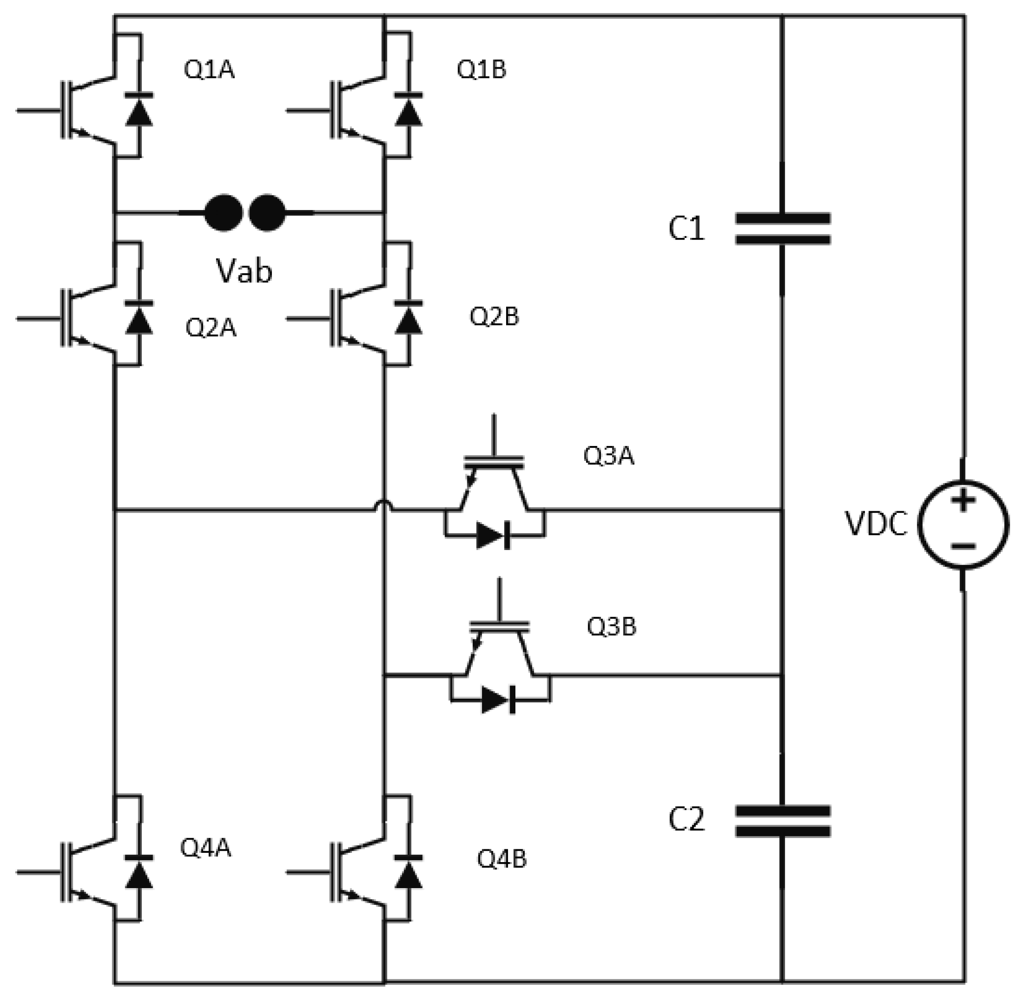
Figure 2.
F-type inverter switching cases.
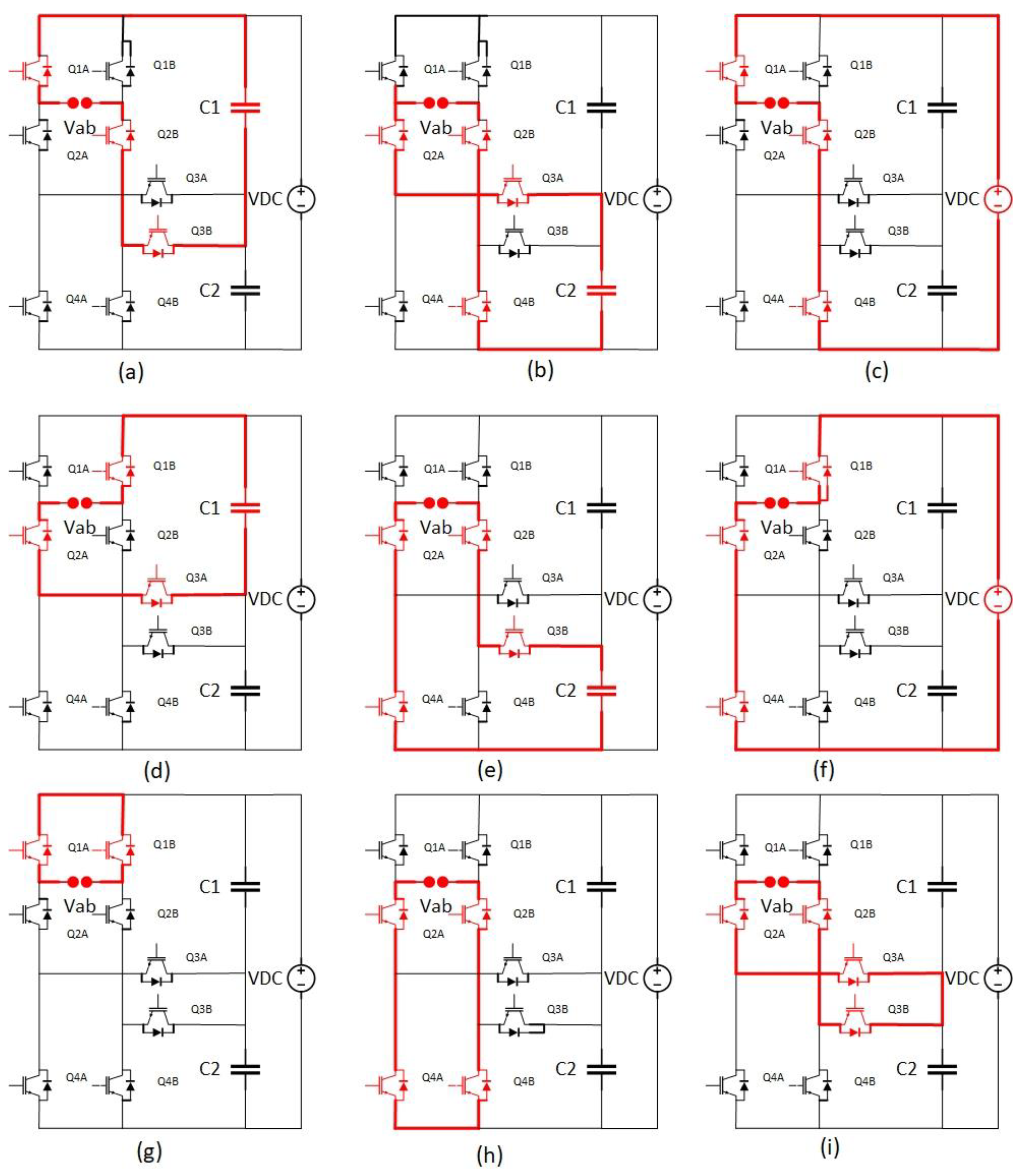
Figure 3.
GCFTPV working flowchart.
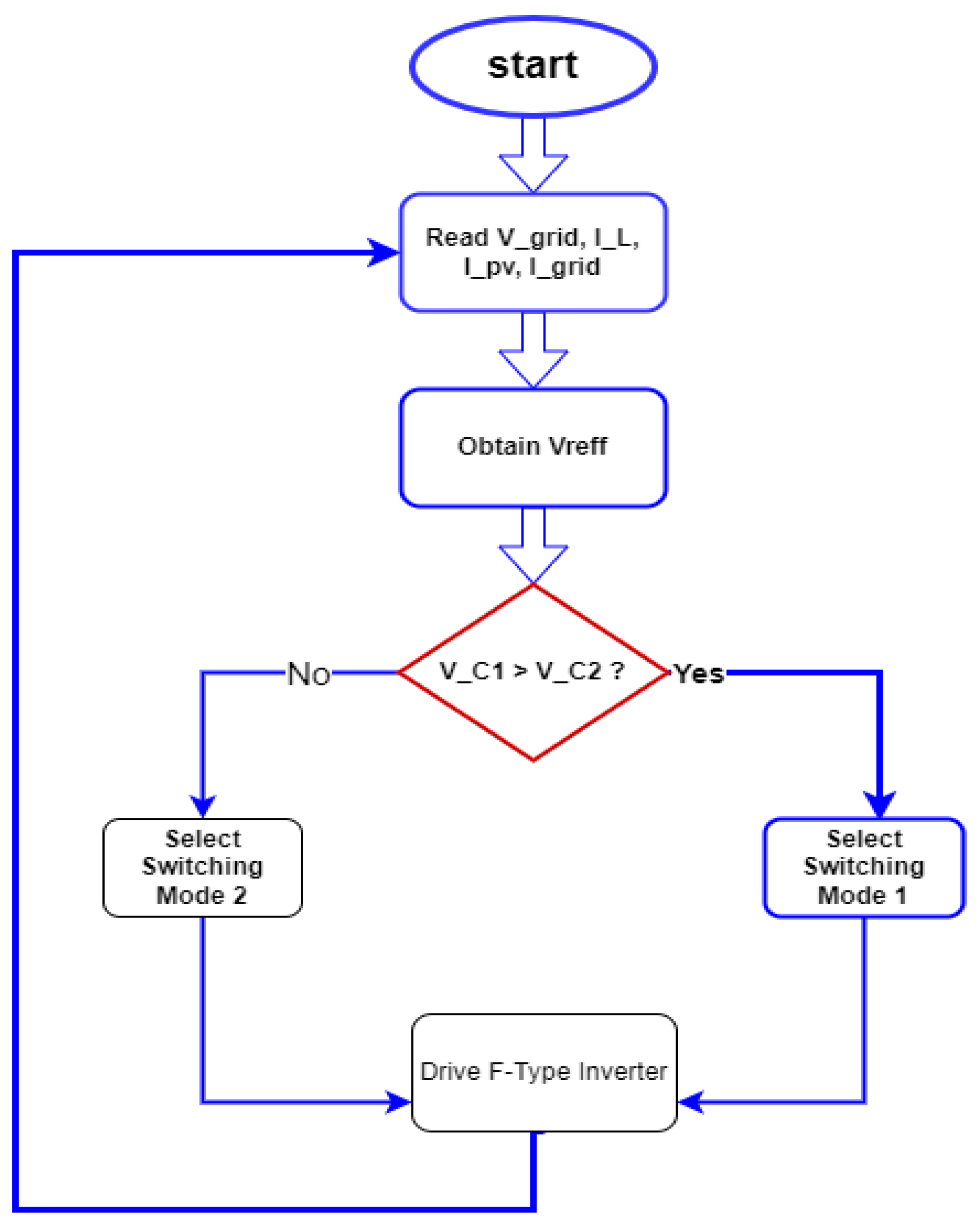
Figure 4.
Reference and carrier waveforms.
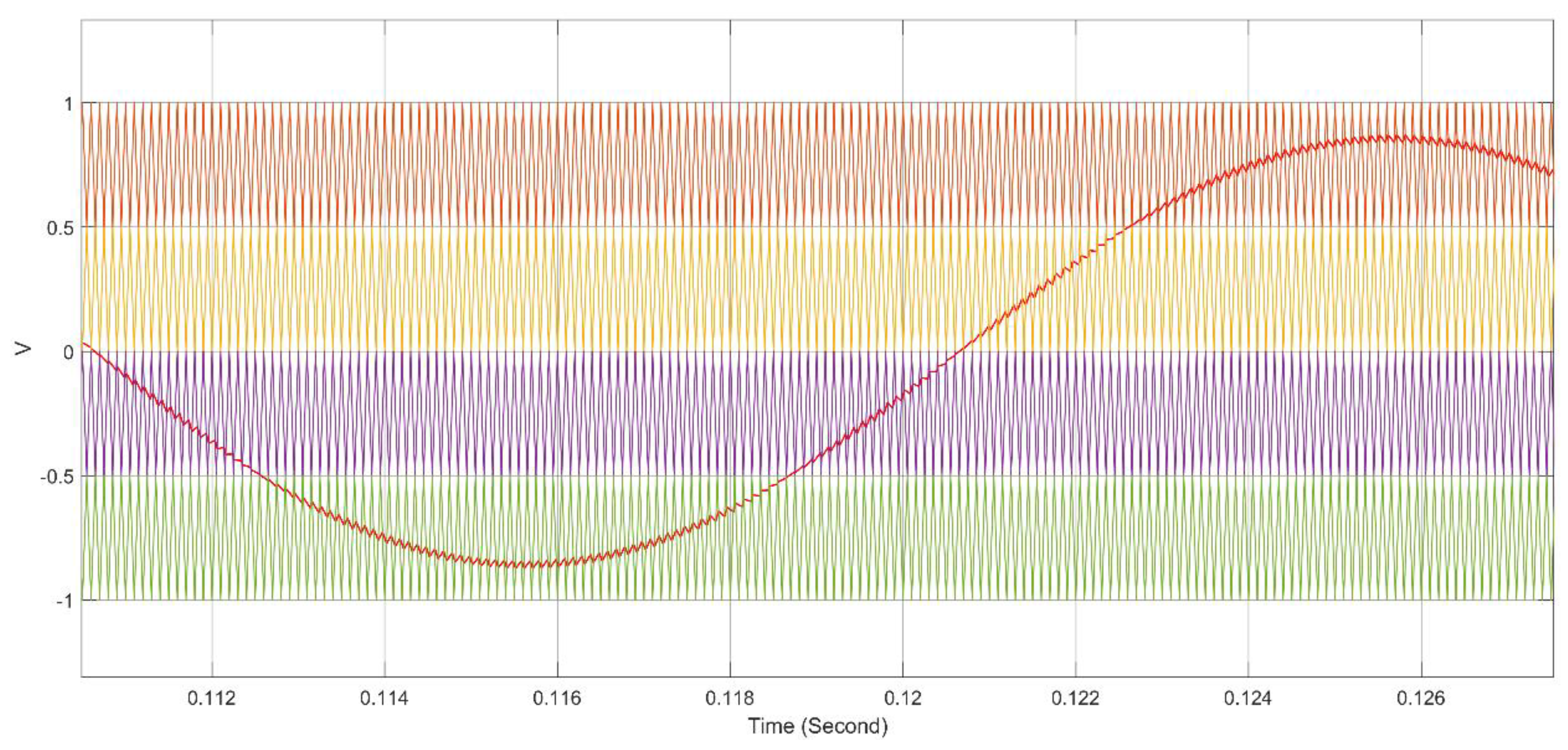
Figure 5.
Voltage stress on each switch in the proposed system.

Figure 6.
Switching losses for all switches in the proposed system.
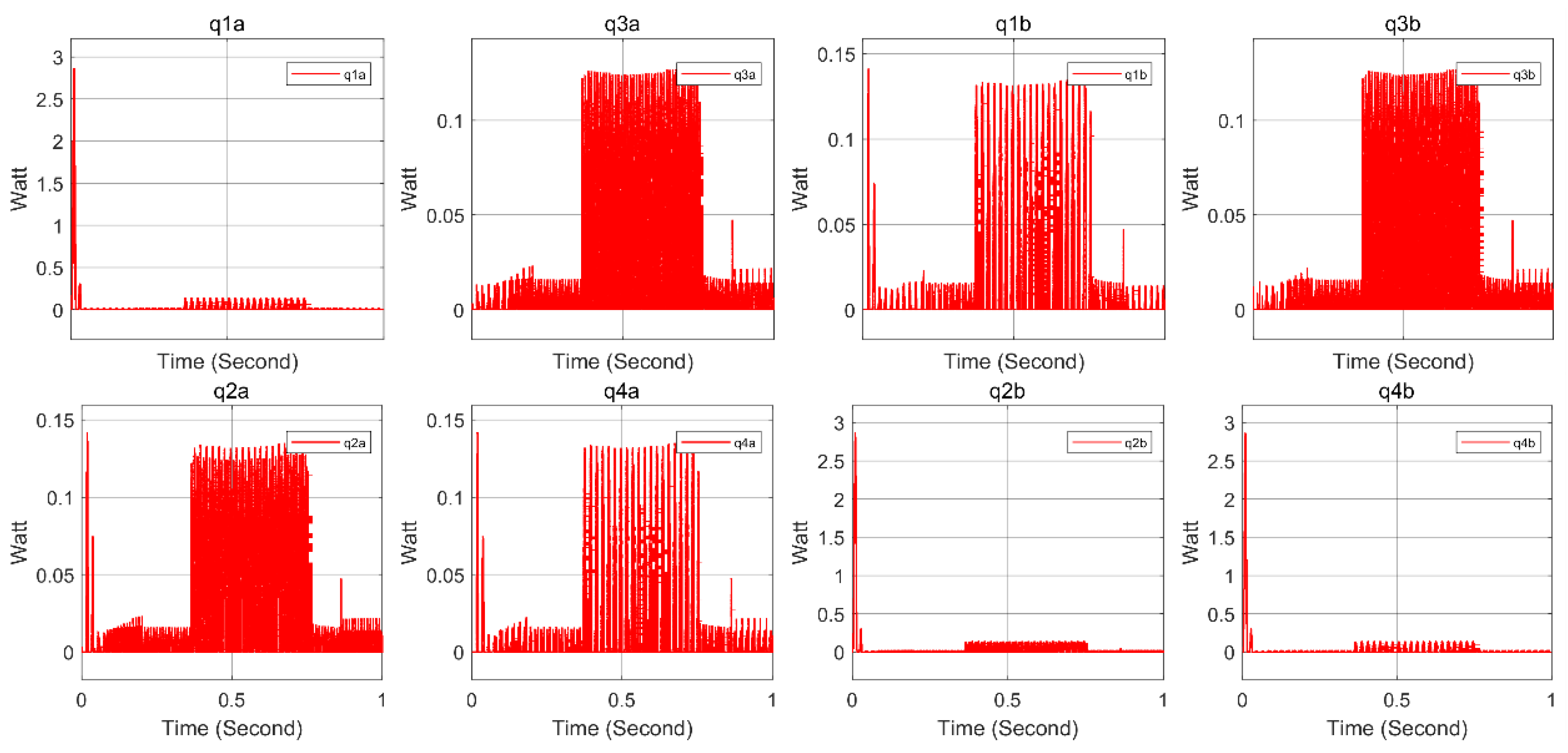
Figure 7.
Inverter and main capacitors voltage waveforms.
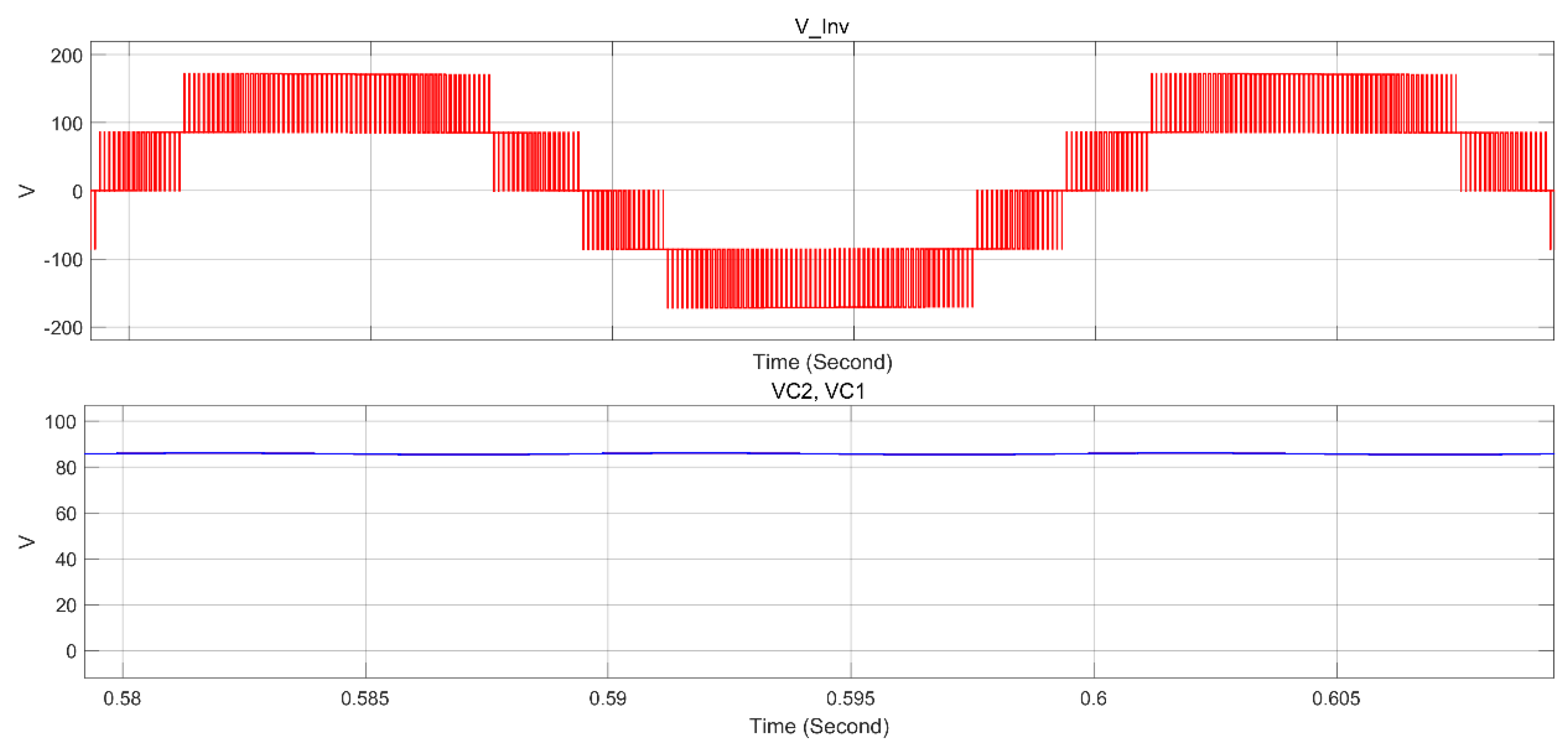
Figure 8.
System simulation results when the PV array is idle.
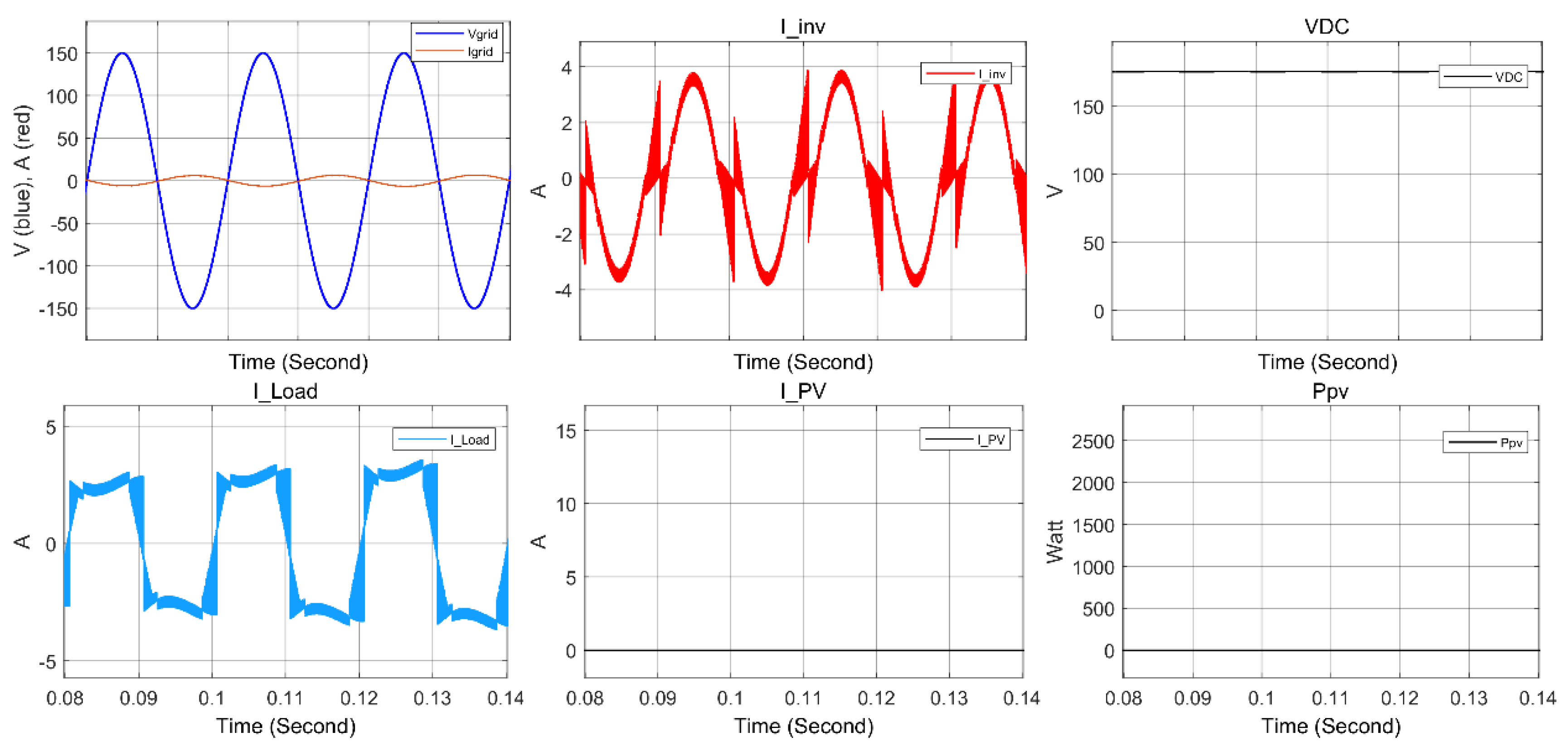
Figure 9.
Load current FFT analysis.
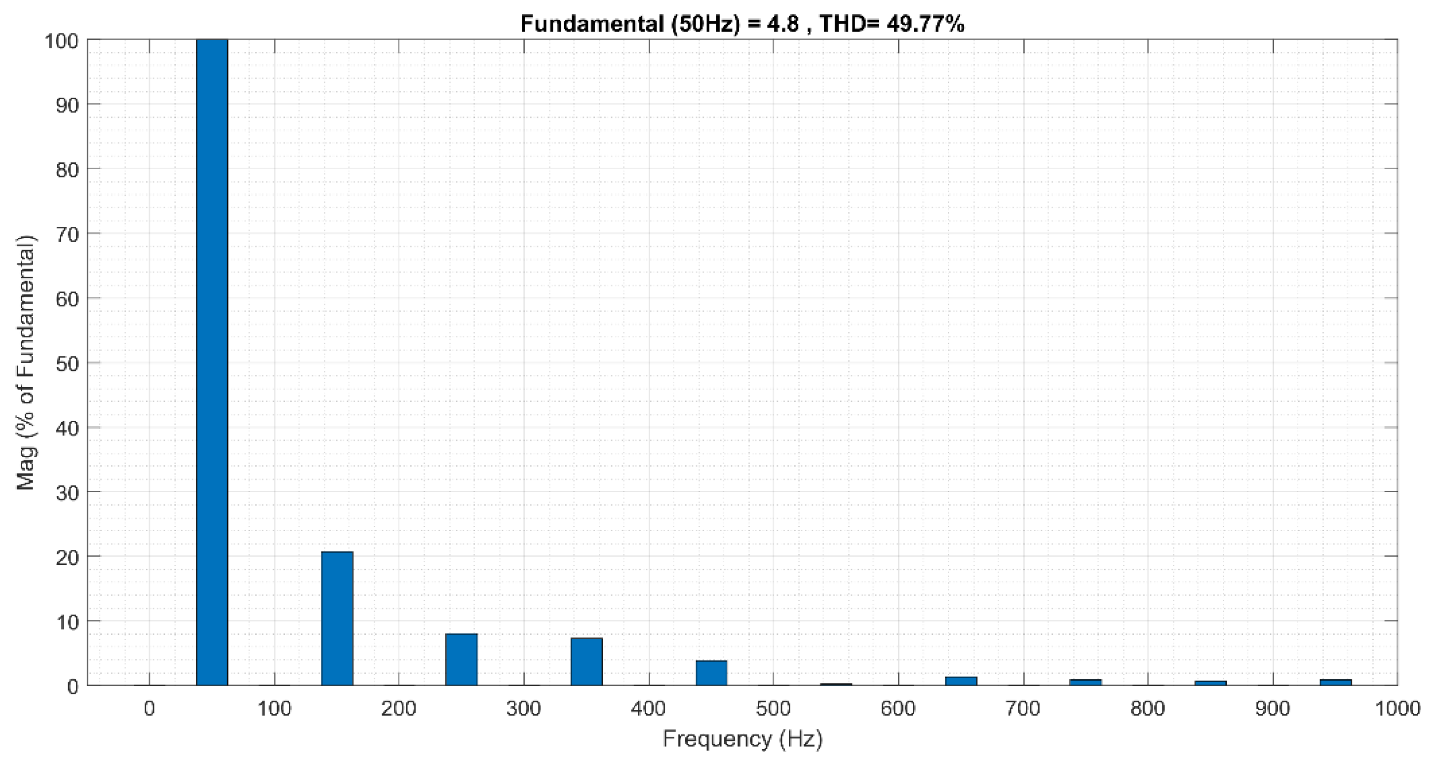
Figure 10.
Grid current FFT when PV array is idle.
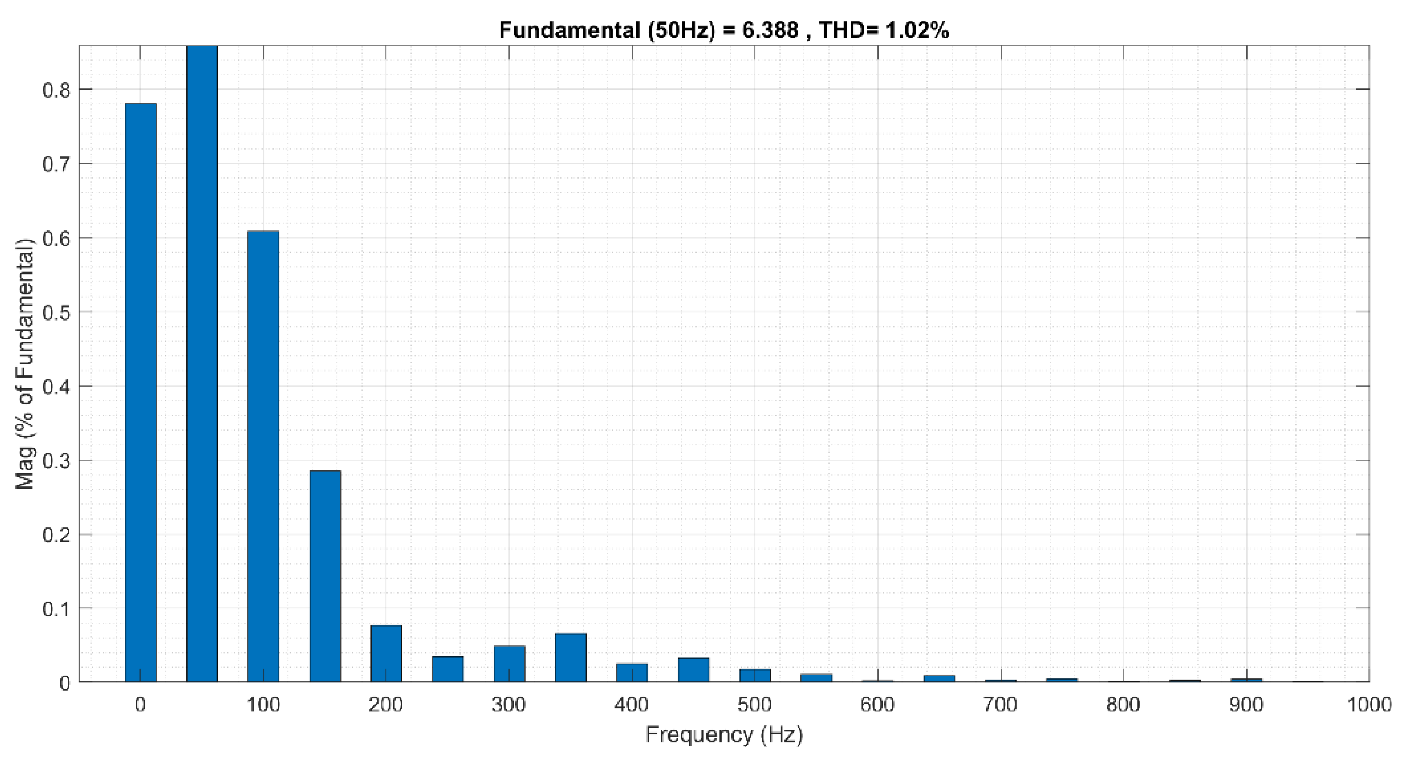
Figure 11.
System simulation results when Ppv = Pload.
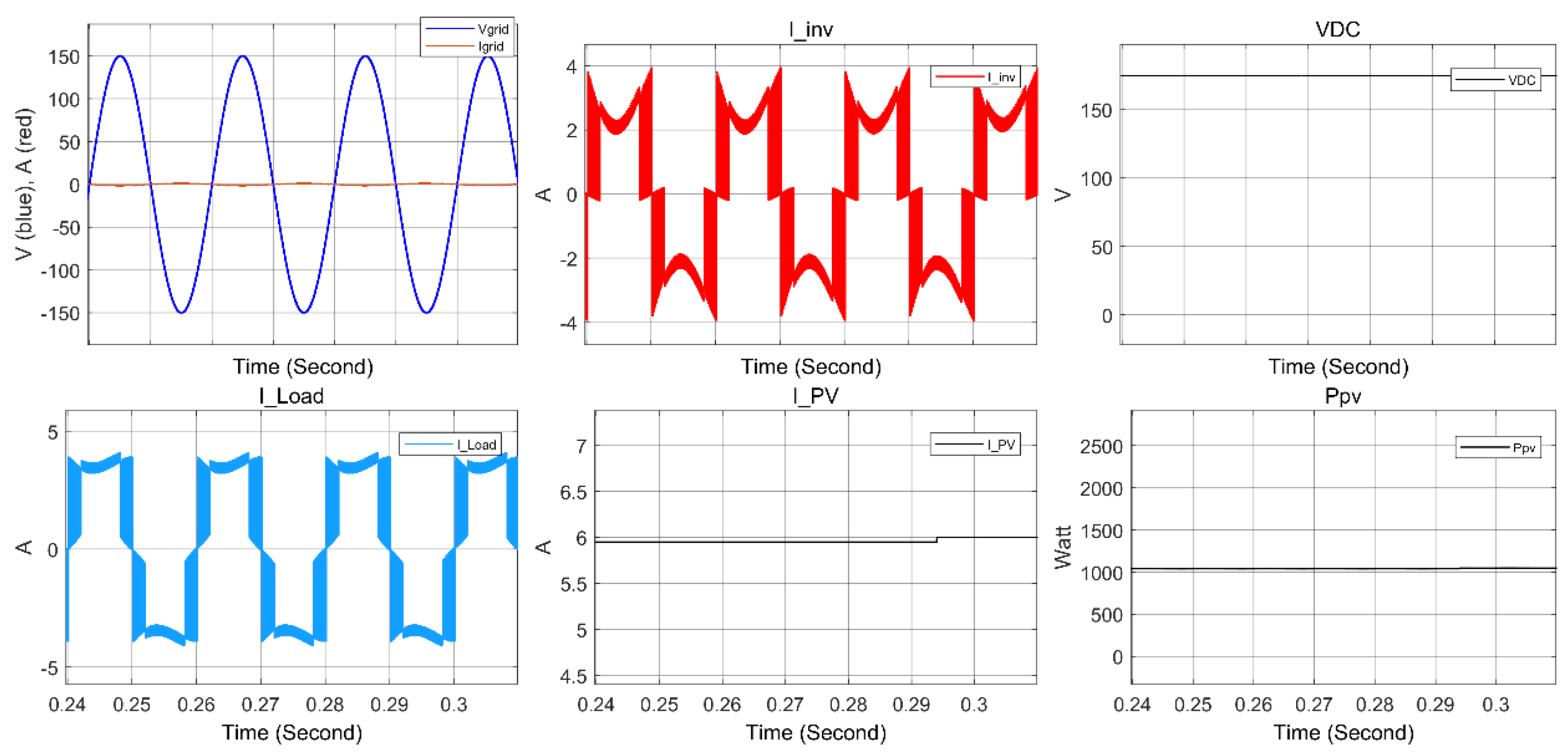
Figure 12.
Grid current FFT when Ppv = Pload.
Figure 13.
System simulation results when Ppv > P load.
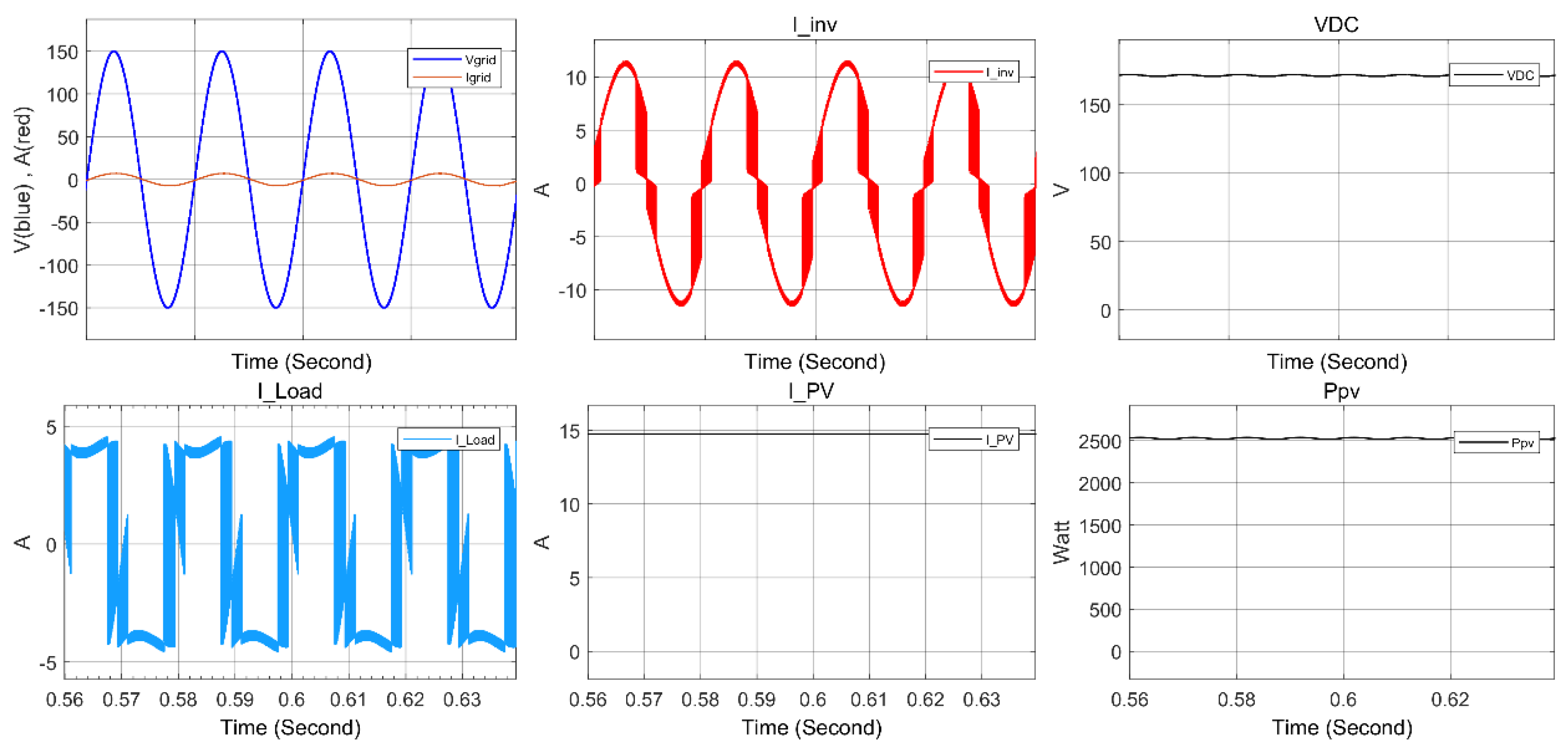
Figure 14.
Grid current FFT when Ppv > P load.
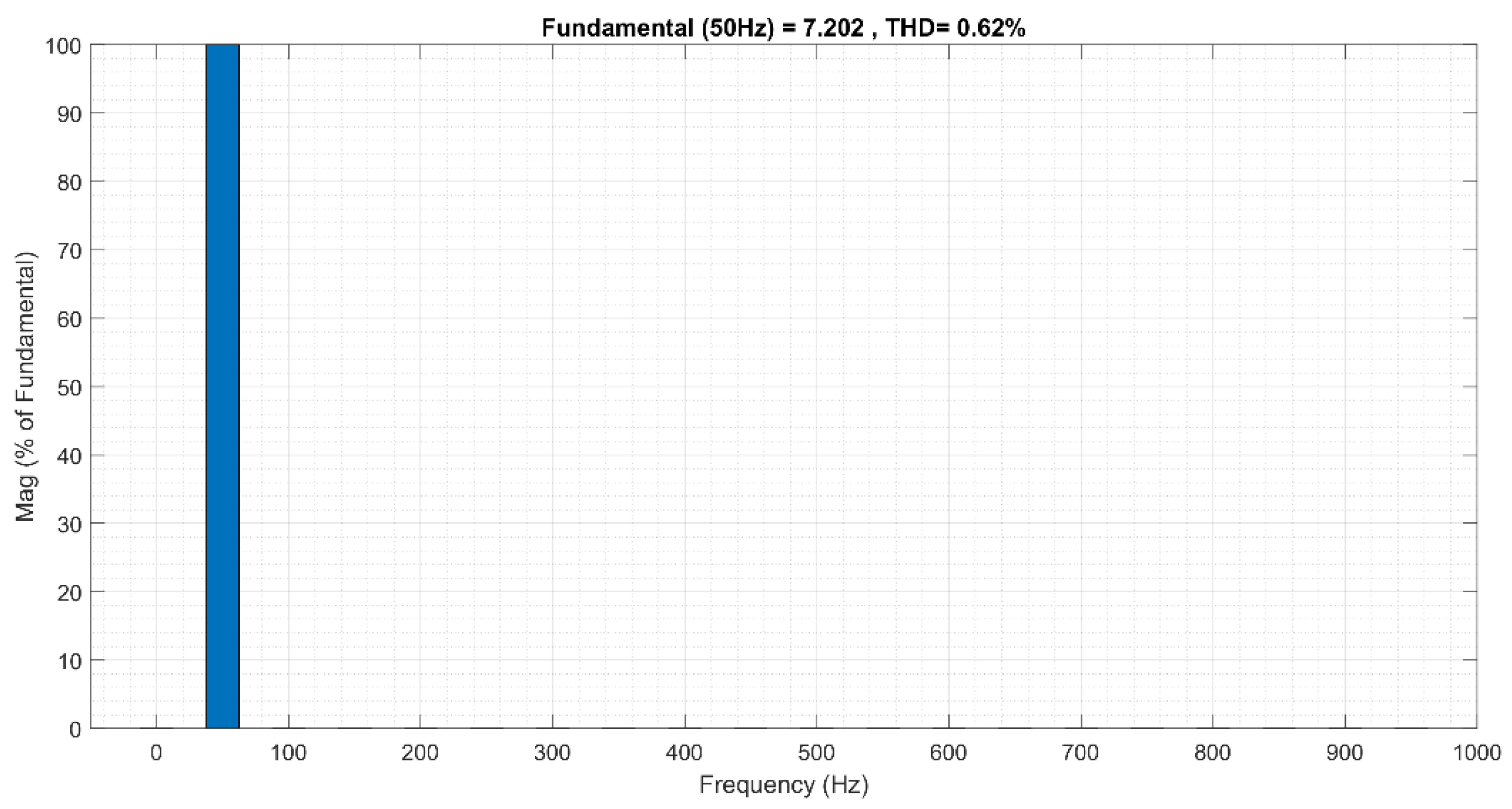
Figure 15.
Switching losses for the proposed system in all simulated cases.
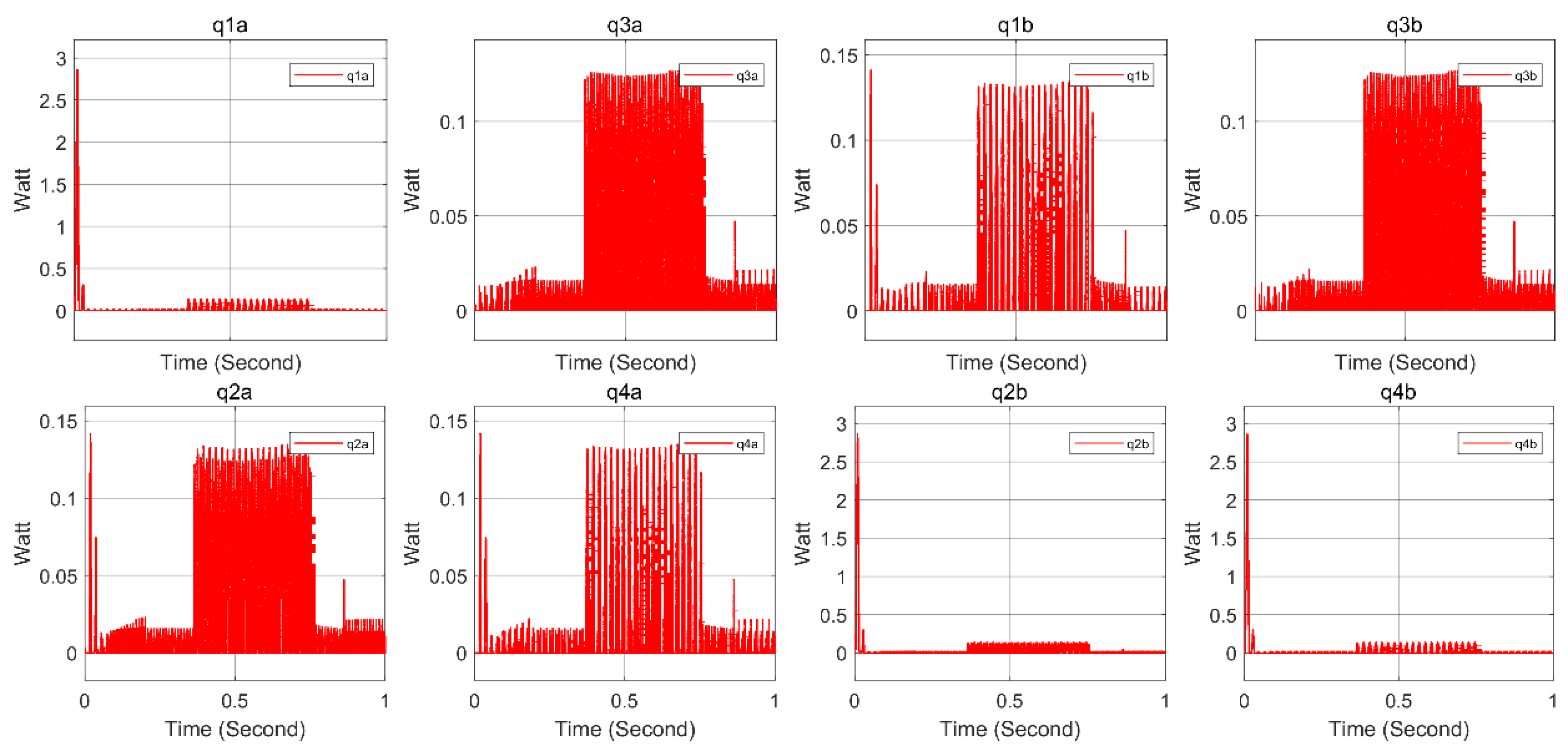
Figure 16.
Voltage and current applied to each IGBT in the F-type inverter.
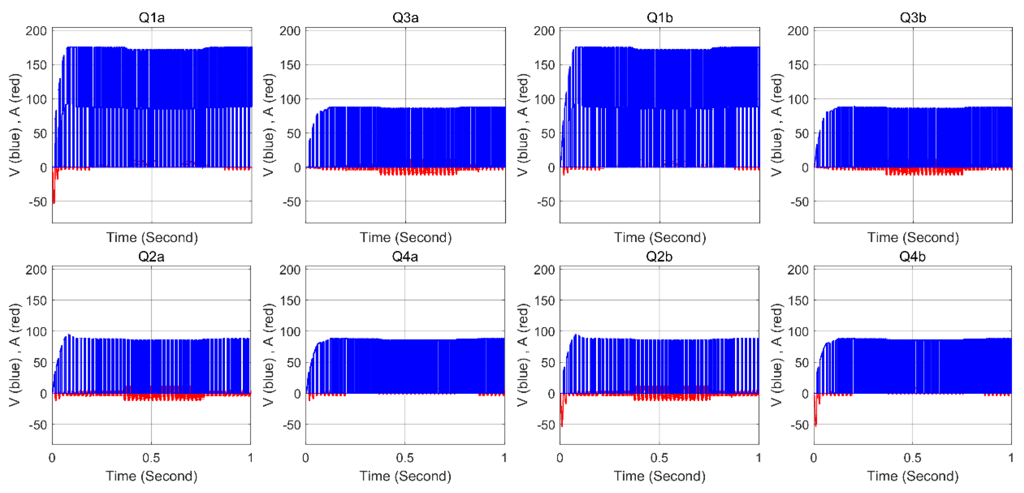

Table 1.
The switching cases and related output voltages.
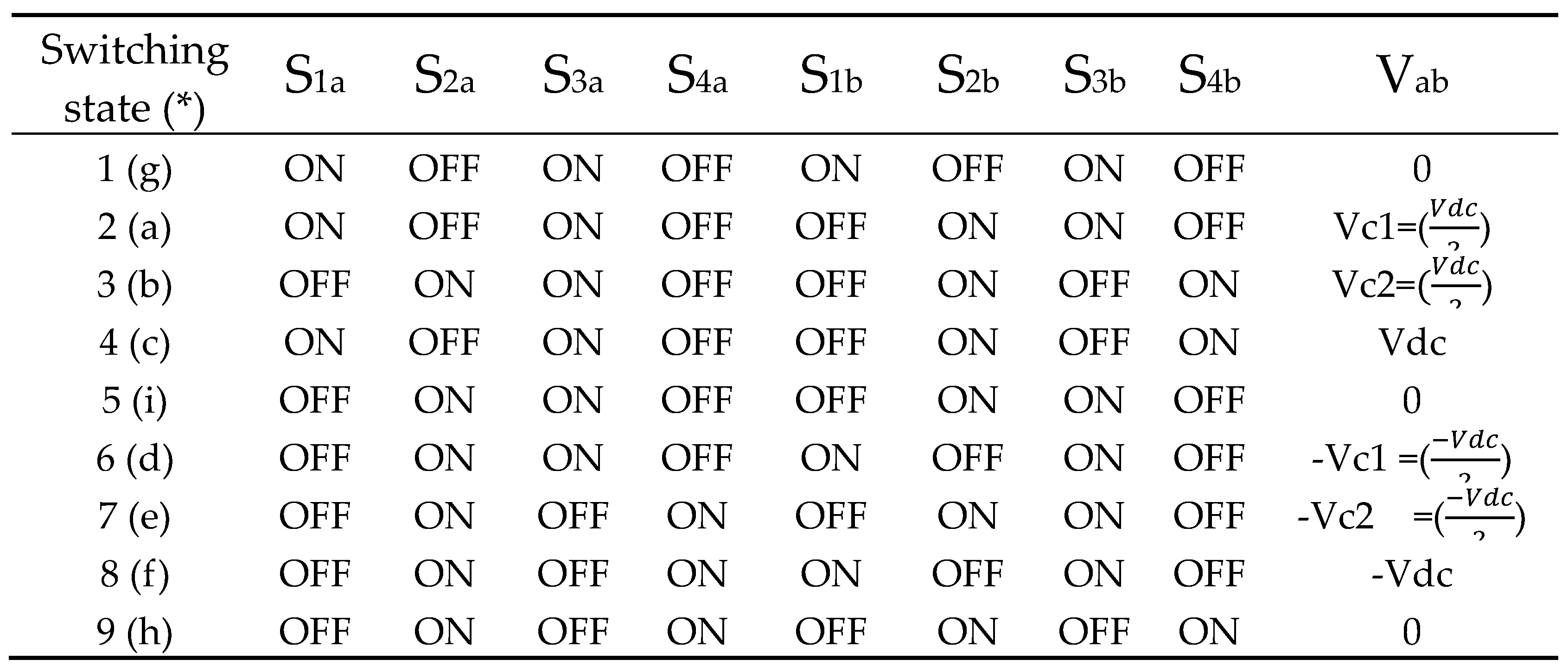
Table 2.
Performance comparison for F-type and T-type inverters under the proposed control scheme.
| I PV (A) | 0 | 6 | 14.75 |
| I grid (F-type) (A) | 6.98 | 1.32 | 7.145 |
| I grid (T-type) (A) | 7.43 | 1.64 | 6.87 |
| THD (F-type) (%) | 0.73 | 3.58 | 0.62 |
| THD (T-type) (%) | 0.57 | 2.45 | 0.54 |
Disclaimer/Publisher’s Note: The statements, opinions and data contained in all publications are solely those of the individual author(s) and contributor(s) and not of MDPI and/or the editor(s). MDPI and/or the editor(s) disclaim responsibility for any injury to people or property resulting from any ideas, methods, instructions or products referred to in the content. |
© 2023 by the authors. Licensee MDPI, Basel, Switzerland. This article is an open access article distributed under the terms and conditions of the Creative Commons Attribution (CC BY) license (http://creativecommons.org/licenses/by/4.0/).
Copyright: This open access article is published under a Creative Commons CC BY 4.0 license, which permit the free download, distribution, and reuse, provided that the author and preprint are cited in any reuse.


