Submitted:
29 May 2023
Posted:
30 May 2023
You are already at the latest version
Abstract
In response to the fire protection design challenges faced by the integrated station-city engineering under the new model of station-city fusion, such as large building volume, diverse traffic types, functional integration, spatial complexity, and inapplicable standards, this paper selects Chongqing East Station as a typical engineering case. The fire safety engineering methods and performance-based fire protection design ideas were used. The paper summarized the fire protection difficulties, such as multifunctional combination construction, large fire protection distance, large fire protection zoning area, long evacuation distance, and design of evacuation (quasi) safety zones. Combining with the actual situation of the engineering, this paper analyzed the basic technical measures taken to address these design challenges. By adopting the method of fire safety engineering, the safety of the design scheme is verified, which can provide a solution approach for the current fire protection design challenges in the integrated station-city engineering.
Keywords:
station-city integration
; Chongqing East station
; combined construction
; Evacuation (quasi) safety zone
1. Introduction
With the construction and development of China’s railway transport system and urban transportation facilities, some comprehensive railway stations have been completed one by one. As an important part of urban development, railway hub stations play a crucial role in implementing the strategy of Integrated Station-City Development(ISCD) [1,2]. The new generation of high-speed railway station transfer hubs is expected to meet the requirements of the station-city integration [3]. Multiple transportation modes, such as subway and light rail, have been introduced to form a comprehensive transportation hub that links railways and cities. The railway station has gradually shifted its status from a single transportation hub to a diversified urban node integrating transportation, entertainment, leisure, business, office, residence, and other functions. Urban design model for areas around transit stations is actively promoted by transit-oriented development [4]. Some high-speed railway station platforms and transfer halls are set underground, which makes it more difficult for quick and effective evacuation [5,6].
The interaction between high-speed railway station buildings and cities has been increasingly highlighted in the design of these buildings. In order to maximize regional comprehensive value and achieve intensive, high-quality use of land resources, the concept of station-city integration has come into being. Integrated station-city engineering, which features large building volume, complex traffic flow lines, spatial complexity, multi-functional integration and intercommunication, is a new form of station building construction. Generally, the railway, rail transit, public transportation, social transportation, and other transportation modes are integrated in the integrated station-city engineering. For this reason, in order to provide convenient conditions for personnel transfer, spaces within the transportation hub remain connected. As a result, the fire protection zoning area and evacuation distance generally exceed the requirements specified in related specifications. Given the complex design, construction, and operation of large-scale public buildings for transportation, the main objectives of fire prevention design are to prevent and control fire and ensure the safety of personnel evacuation. As civil buildings and transportation hub buildings are increasingly integrated, garages are becoming more critical in affecting the fire and smoke spread throughout the buildings. Garages represent an important component of the integrated station-city engineering. In particular, with the increasing number of new energy vehicles in recent years, garage fires have become a significant concern due to the large volume of smoke produced, the added difficulty in personnel evacuation, the significant challenges they pose to firefighting efforts and great fire hazards. This has posed even greater challenges to the fire prevention design of such integrated transportation hub projects. The complex spatial characteristics of integrated transportation hub projects can also bring great difficulties for the safe evacuation of personnel in the event of an emergency. Based on the evacuation path network, evacuation path allocation model and the dynamic transmission model for personal evacuation within transit-oriented developments (TOD), some scholars have conducted analyses on evacuation demand distribution and situation under emergency evacuation within the TOD [7]. The above analysis indicates that traditional fire protection design schemes are difficult to meet the functional requirements under this new building technology situation. As a result, fire protection design challenges such as combined construction and zone expansion for such projects always follow. To achieve a safe evacuation, the Available Safe Egress Time (ASET) should be larger than the Required Safe Egress Time (RSET) for the agreed scenarios [8]. It was reported that the safe zone has an effective role in reducing evacuation. Besides, other aspects such as ventilation, structure, and population management were also suggested for the further investigation of the safe zone [9].
The Chongqing East Station Building and Supporting Comprehensive Transportation Hub Project is a highly representative pilot project for the “Station-City Integration Development” in the demonstration zone for building a strong transportation network in Chongqing. This paper, with Chongqing East Station as a case, analyzes the difficulties in fire prevention design and the fire safety strategies adopted, with a view to providing a reference for the fire prevention design of similar integrated station-city engineering.
2. Project Overview
Chongqing East Station is located in the eastern trough of the main urban area of Chongqing. It represents one of the four main passenger stations in the Chongqing transportation hub. Three major works, including the station building and related works, supporting and integrated development works of the railway hub, and municipal transportation, are built. The station is a comprehensive railway transportation hub that focuses on high-speed rail and integrates urban rail transit, bus, coach taxi services, and commerce and office spaces into one.
In terms of scale, Chongqing East Station includes a total of 15 platforms and 29 lines, with a maximum gathering capacity of 15,000 people and a peak-hour traffic volume of 16,274 people. The core area designed for this project is 620m wide from north to south and 653m long from east to west. The station building and related works are the main parts of this project. The comprehensive transportation and transfer center is located west of the main station building. The station building panel and the comprehensive transportation center image roof panel have been designed to form a large roof panel. The supporting buildings of the railway hub are located at four corners of the station building. The bus and coach yards are located under the railway bridge on the south side of the station. Subway stations and sections of Lines 6, 8, 24, and 27 are located below the station building. The overall layout of the station is shown in Figure 1.
Chongqing East Station utilizes the current terrain elevation difference and follows the design concept of “station-city integration”. It adopts a three-dimensional layout with eight floors up and down and interconnected space and a total floor area of up to 123.15*104m2.
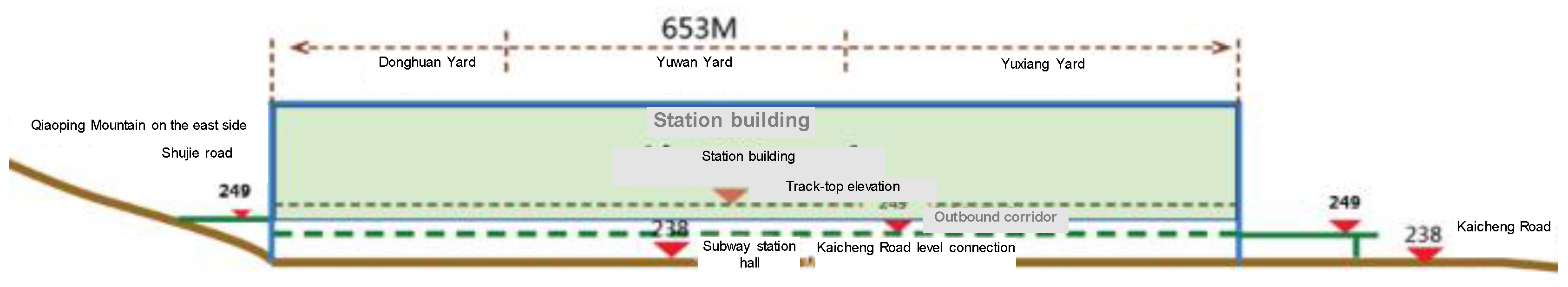
The ground elevation of the municipal Shujie Road on the east side of this project is 249.00m, that of the municipal Kaicheng Road on the west side is 238.00m, and that of the eaves of the station building is 300.10m. The elevation and main functions of each floor are shown in Table 1 and Figure 2.
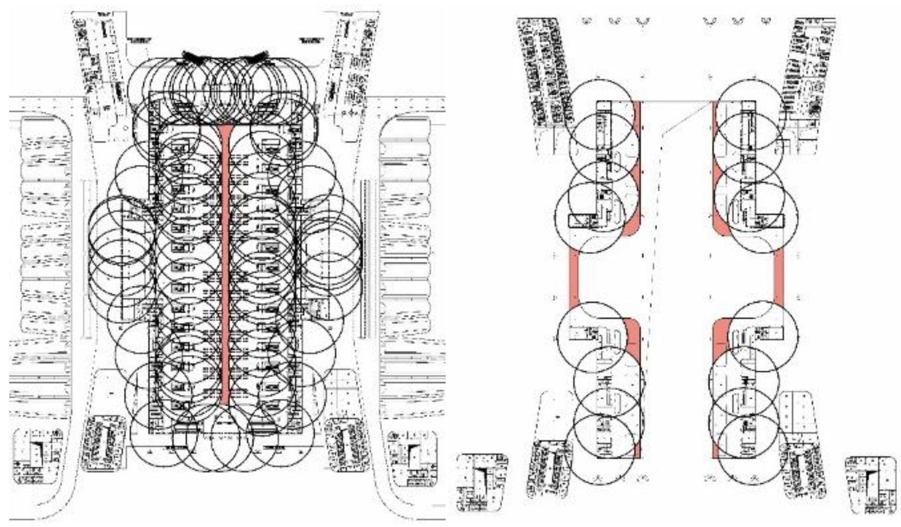
Multiple levels of fire lanes and evacuation and rescue surfaces are formed in Chongqing East Station based on the terrain elevation difference and through the use of multi-point elevation entry and exit and five-storey three-dimensional traffic evacuation, as shown in Figure 3.
The rail transit project is located below the railway station, with a total of six floors. The deepest station surface (subway line 6/27 platform) is 17.4m above the ground of the municipal Kaicheng Road, making it an underground station for multi-line transfer. The fire protection features of the station are designed as per the standard for the underground station.
3. Problems and Difficulties for Fire Protection Design
3.1. Difficulties in fire protection design of multifunctional combined construction
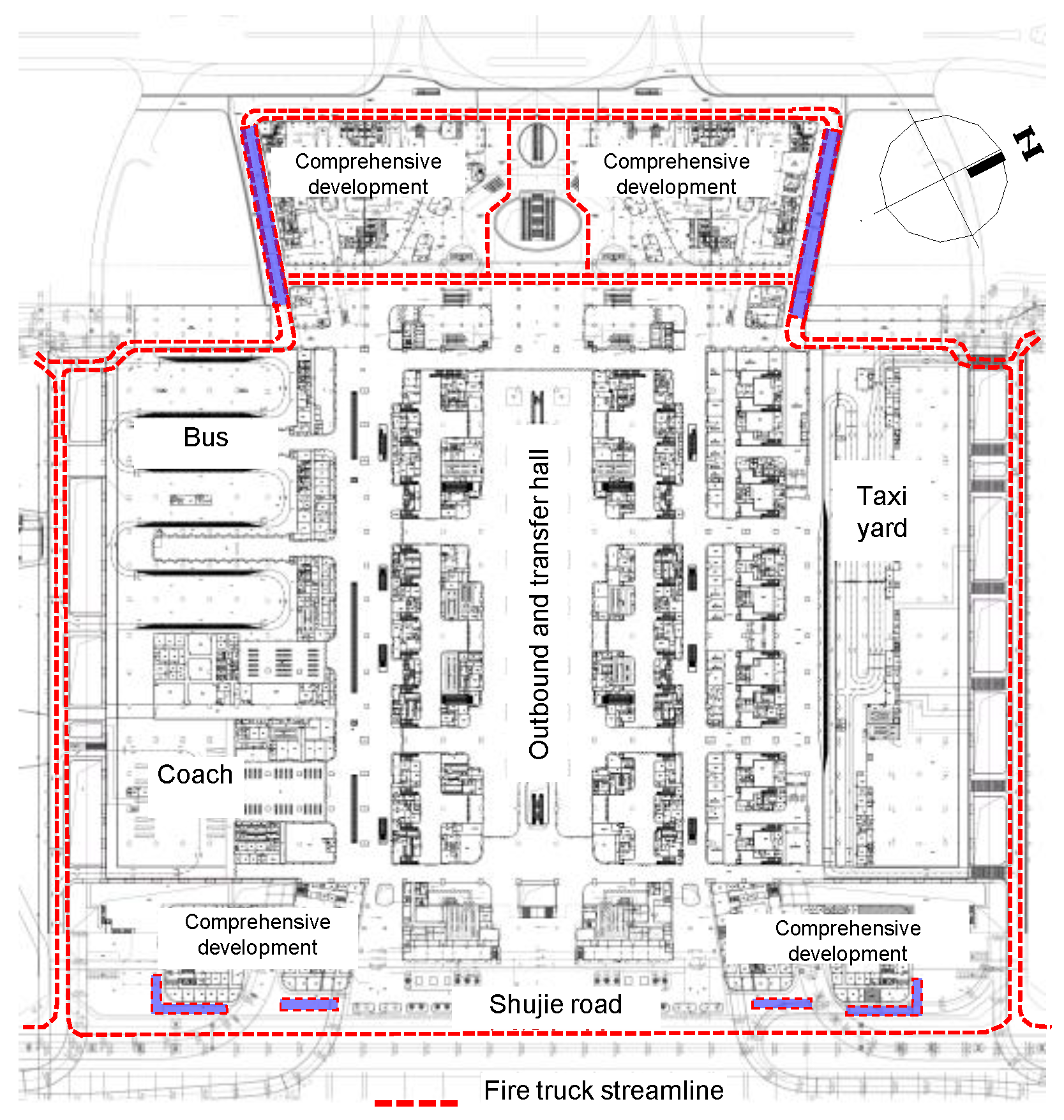
In order to achieve the integration and interconnection of multiple functions, the station building has been constructed in combination with supporting bus hubs, a coach and tourism distribution center, and a taxi yard on the outbound floor, as shown in Figure 4.
In fire protection design, the railway station building of this project takes the outbound floor as the first floor. The height of the highest point of the station building from the municipal Shujie Road (at 249.00m) is 57.90m. According to the Code for Fire Protection Design of Buildings (GB 50016-2014) (2018 Edition) in China, station buildings are classified as public buildings with a height greater than 50m. However, according to Article 6.1.8 of the Code for Fire Protection Design of Railway Engineering (TB 10063-2016), the height of the elevated waiting hall ground (at an elevation of 270.10m) from the platform level entrance and distribution hall ground (at an elevation of 260.20m) is 9.9m. Although the building has a height greater than 24m, its fire protection design can still be carried out in accordance with the provisions of the Code for Fire Protection Design of Buildings (GB 50016) for the category of single and multi-storey civil buildings.
Based on the qualitative analysis of the above buildings, the fire protection design standards for the bus hub, coach and tourism distribution center, taxi yard, and other auxiliary functional areas arranged on the outbound floor of the station building are consistent with those of the station building, all of which are designed in accordance with the standard for multi-storey buildings above the ground.
For the architectural layout form of station-city integration, whether the qualitative analysis of the above buildings and the adopted fire protection standards can meet the fire safety requirements remain to be analyzed.
3.2. Difficulties in designing multi-level fire separation distance
In terms of the overall layout of this project, the east and west comprehensive development houses are arranged at four corners of the station building. Among them, the east one has a total of nine floors above the ground of the municipal Shujie Road, and one floor below the ground of the same road. The height of the building roof from the ground level of Shujie Road is 43.55m. The west comprehensive development house has a total of nine floors above the ground of the municipal Kaicheng Road, and three floors below the ground of Kaicheng Road. The height of the building roof from the ground of Kaicheng Road is 49.15m. In the fire protection design for buildings, there are four comprehensive development houses at four corners. All of these buildings are independently designed in accordance with the standard for fire protection of Class I high-rise public buildings.
However, in order to achieve intercommunication and seamless docking of various functions, large communication platforms have been set up between the station building and the comprehensive development houses on the outbound floor, platform floor, and elevated waiting floor. the fire separation distance between the station building and the comprehensive development houses in this project cannot be seen from the sky due to platform obstructions, and thus cannot meet the provisions of Article 2.1.21 of the Code for Fire Protection Design of Buildings (GB 50016-2014) (2018 Edition).
Figure 5.
Schematic diagram of the connection platform between the comprehensive development house on the west side of the platform floor and the station room.
Figure 5.
Schematic diagram of the connection platform between the comprehensive development house on the west side of the platform floor and the station room.
3.3. Difficulties in fire separation and evacuation design for super-large fire compartment
The railway station building of this project adopts a large integrated spatial layout, with internal connections from top to bottom, spanning the outbound floor, platform floor, elevated floor, and travel service mezzanine. As an expanded fire compartment, it has an area of 108,090m2 (see Table 2), which cannot meet the requirements of Article 6.1.2 of the Code for Fire Protection Design of Railway Engineering (TB 10063-2016).
In view of the large building size and the use of stairs leading to the platform as evacuation exits in the elevated waiting hall, the farthest straight evacuation distance inside the waiting hall is about 45m, and the farthest straight evacuation distance in the public area of the elevated travel service mezzanine is about 70m, which cannot meet the requirements of Article 6.1.10 of TB 10063-2016.
Figure 6.
Schematic diagram of the super-long evacuation distance area of the elevated waiting hall
3.4. Difficulties in evacuation (quasi) safety zones
For “zero-distance” rapid transfer, Chongqing East Station adopts a three-dimensional layout, with each main functional area stacked vertically. Due to the streamlined form of railway entry and exit, the outbound hall, rapid entry hall, bus hub station, coach and tourism distribution center, hub supporting yard, subway station, comprehensive development houses, and other functional areas of this project are all arranged below the railway station yard.
As a super-large station building, the span of Chongqing East Station exceeds 600m, and vertical evacuation stairs cannot be set within this range. As a result, evacuation exits from the above functional areas cannot directly lead to the outdoor area. So, it is necessary to set up (quasi) safety zones for personnel evacuation on the outbound floor, comprehensive transportation and transfer floor, and subway station hall floor below the station based on actual engineering conditions to achieve safe evacuation of personnel.
4. Fire Protection Design Schemes
4.1. Fire protection design scheme for multifunctional combined construction
The outbound floor of the station building in this project is open on all four sides, and the east side is connected to the ground of the municipal Shujie Road. The buildings above this floor are all located above the municipal road surface (the elevation of the municipal Kaicheng Road is 238.00m, and the elevation of Shujie Road is 249.00m).
Figure 7.
Schematic diagram of the vertical layout of the building
The outbound floor is provided with a circular fire lane, which meets the conditions for fire rescue. Thus, it can serve as the first floor of the station building.
Figure 8.
Layout plan of circular fire lane at the exit layer (249.00m)
Starting from an elevation of 249.00m, the station building has a total of three floors above ground (outbound floor, platform floor, and elevated floor). The outbound floor has a height difference of 21.1m, less than 24m, from the elevated floor. The elevated floor of this project is also provided with a circular fire lane, with favorable conditions for fire rescue and personnel evacuation. Based on the above favorable conditions, the station building of this project can be designed as per the standard for multi-layer fire protection in accordance with the Code for Fire Protection Design of Railway Engineering (TB 10063-2016).
For the bus hub, coach and tourism distribution center, taxi yard, etc. on the outbound floor, there is a railway yard above them, with only one floor in the building space. The functional areas above are separated from the upper yard by a floor slab with a fire resistance limit of no smaller than 2.0h. On the plane, these areas are also separated from the outbound hall of the station building through firewalls, Class A fire doors, 3.0h fire roller shutters, etc., which effectively reduces the mutual interference between different functional areas. Therefore, the bus hub, coach and tourism distribution center, taxi yard, etc. on the outbound floor can be designed as per the standard of fire protection for multi-story buildings.
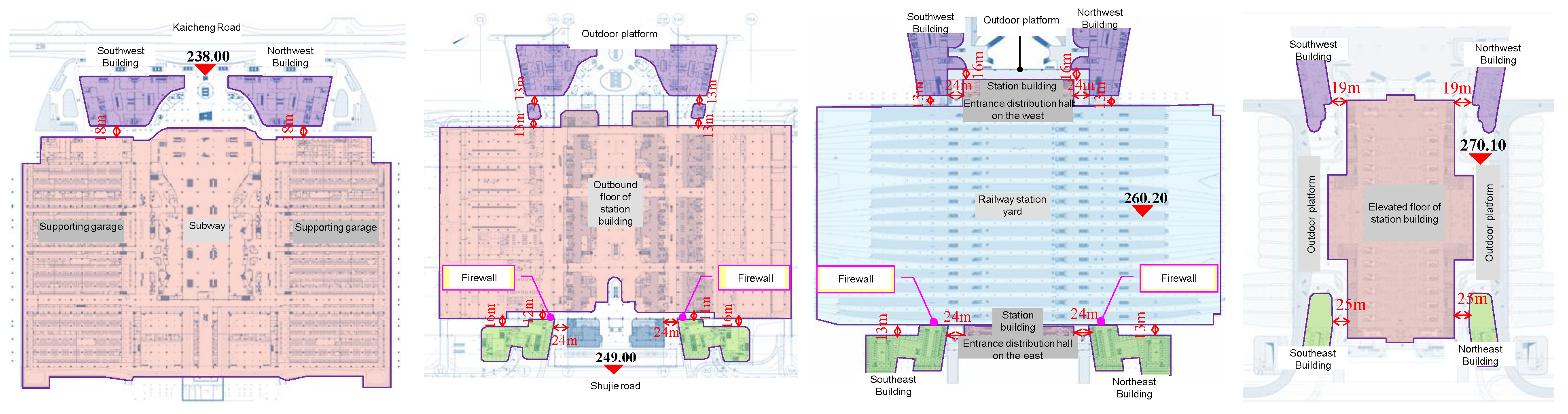
4.2. Design scheme for multi-storey fire separation distance
(1) Subway station hall floor
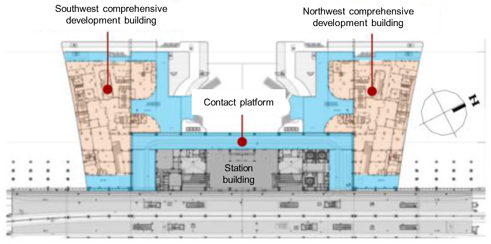
This floor connects the municipal Kaicheng Road on the west. A spacing of 18m is maintained between the southwest and northwest comprehensive development buildings and the exterior walls of the rail transit and supporting garage buildings, with the sides fully open and a floor height of 11m. The exterior walls are separated by a 1.0h Class A fireproof glass wall for fire protection.
(2) Outbound floor
This floor connects the municipal Shujie road on the east. A spacing of 12m to 16m is maintained between the southeast and northeast comprehensive development buildings and the exterior walls of the station building in the east-west direction. The sides are fully open, with a floor height is 11 meters. A firewall is installed at a spacing of 12 meters. A spacing of 24m is maintained in the north-south direction, and a 1.0h Class A fireproof glass wall is used for fire separation on the exterior wall.
A spacing of 13m is maintained between the southwest and northwest comprehensive development buildings and the exterior walls of the station building, with the sides fully open and a floor height of 11m. The exterior walls are separated by a 1.0h Class A fireproof glass wall for fire protection.
(3) Platform floor
At the 260.20m level high-rise building, A spacing of 13m to 24m is maintained between the southwest and northwest buildings of the comprehensive development and the exterior walls of the station building, with the sides fully open and a floor height of 9.9m.
A spacing of 13m to 24m is maintained between the southeast and northeast comprehensive development buildings and the exterior walls of the station building’s outbound floor, with a floor height of 9.9m. Firewalls without doors, windows, or openings are established near the track area in some areas.
(4) Elevated floor
A spacing of 19m is maintained between the southwest and northwest comprehensive development buildings and the exterior walls of buildings on the elevated building of the station building at an elevation of 270.10m or above. A spacing of 25m is maintained between the southeast and northeast comprehensive development buildings and the external walls of buildings on the elevated floor of the station building.The separation spacing above is not provided with any fixed combustible loads inside, and non-combustible decoration materials are used.
Figure 9.
Schematic diagram of the distance setting between comprehensive development houses and station buildings at different levels.
Figure 9.
Schematic diagram of the distance setting between comprehensive development houses and station buildings at different levels.
4.3. Design scheme for fire separation and evacuation in super-large zones
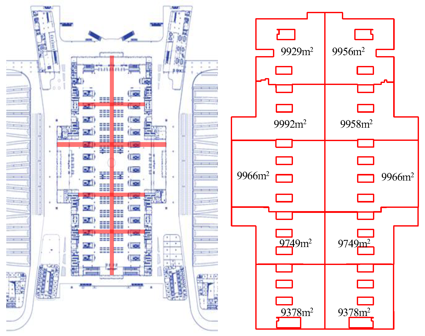
The elevated waiting space is the main part of the expanded fire compartment of the station building in this project. Its design challenges include two aspects: fire separation and safe evacuation. The waiting hall has a clearance height of about 30m. So, conventional fire partition walls and roller shutters cannot be used for separation. The main technical measures taken are as follows:
(1) The elevated waiting space is divided into ten fire control zones with an area of no more than 10,000m2 using fire isolation strips for preventing fire spread and conducting fire linkage control. Isolation strips with a width of no smaller than 6m should be used between control zones for division. Clear signs should be established on the fire isolation strips, and fixed combustible loads may not be set.
Figure 10.
Schematic diagram of division of fire protection control zones in the elevated waiting hall
Figure 10.
Schematic diagram of division of fire protection control zones in the elevated waiting hall
(2) Equipment and management rooms (except toilets, duty rooms and other rooms with small fire loads) and business waiting rooms that are distributed in public spaces and do not meet independent evacuation conditions are designed as fire protection units.
(3) The commercial facilities arranged in the waiting hall are designed as per the standard of fire protection for “fire compartments”, “fuel islands”, etc.
(4) The perimeter of the escalator entrance leading to the platform should be separated from the public space by a 1.0h Class A fireproof glass wall (including doors and windows).
(5) The east-west corridor in the middle of the elevated travel service mezzanine is only used as a personnel passage area, without travel service facilities or combustible materials. The decoration materials should be made of non-combustible materials.
(6) No fuel island style travel service outlets or door and window openings for retail/restaurant establishments should be arranged within a range of 5.0m around the safety evacuation exit.
(7) Non-combustible decoration materials are used for the ceilings, walls, and floors of public areas (excluding rooms). The material combustion performance of the main frame of the waiting seats and the garbage bins is Class A. The combustion performance of wires and cables should not be lower than Class B1.
For evacuation distance, refer to the Code for Fire Protection Design of Civil Airport Terminals (GB51236-2017). The evacuation distance can be increased to 90.0m when the average indoor net height in public areas is larger than 20.0m. The waiting hall space of this project is greater than 20m, with the longest straight evacuation distance being 70m. The technical measures taken for evacuation are as follows:
(1) The width of the main emergency exit in the waiting hall is not less than 3m, and that of the evacuation staircase is not less than 1.6m. The designed evacuation width meets the requirement of 1.0m per 100 persons.
(2) The gates and control doors on the personnel evacuation path should be capable of fire linkage opening.
(3) Movable fences or evacuation swing doors should be set up next to the partition fence and gate in the security check area and shall not be locked. They shall be in an open state in case of fire.
(4) Evacuation guidance should be strengthened. The minimum illumination at the ground level of the evacuation lighting should not be less than 10.0lx, and the centralized power supply battery of the fire emergency lighting and evacuation indication system should have a continuous power supply duration of no shorter than 90 minutes.
(5) Visually continuous light evacuation signs should be added on the ground of the main evacuation path for personnel.
4.4. Design scheme for evacuation (quasi) safety zones
A horizontal evacuation system for personnel at all levels is formed in this project based on the semi-outdoor elevated area, sunken square, and urban corridor to construct an evacuation (quasi) safety zone below the station yard.
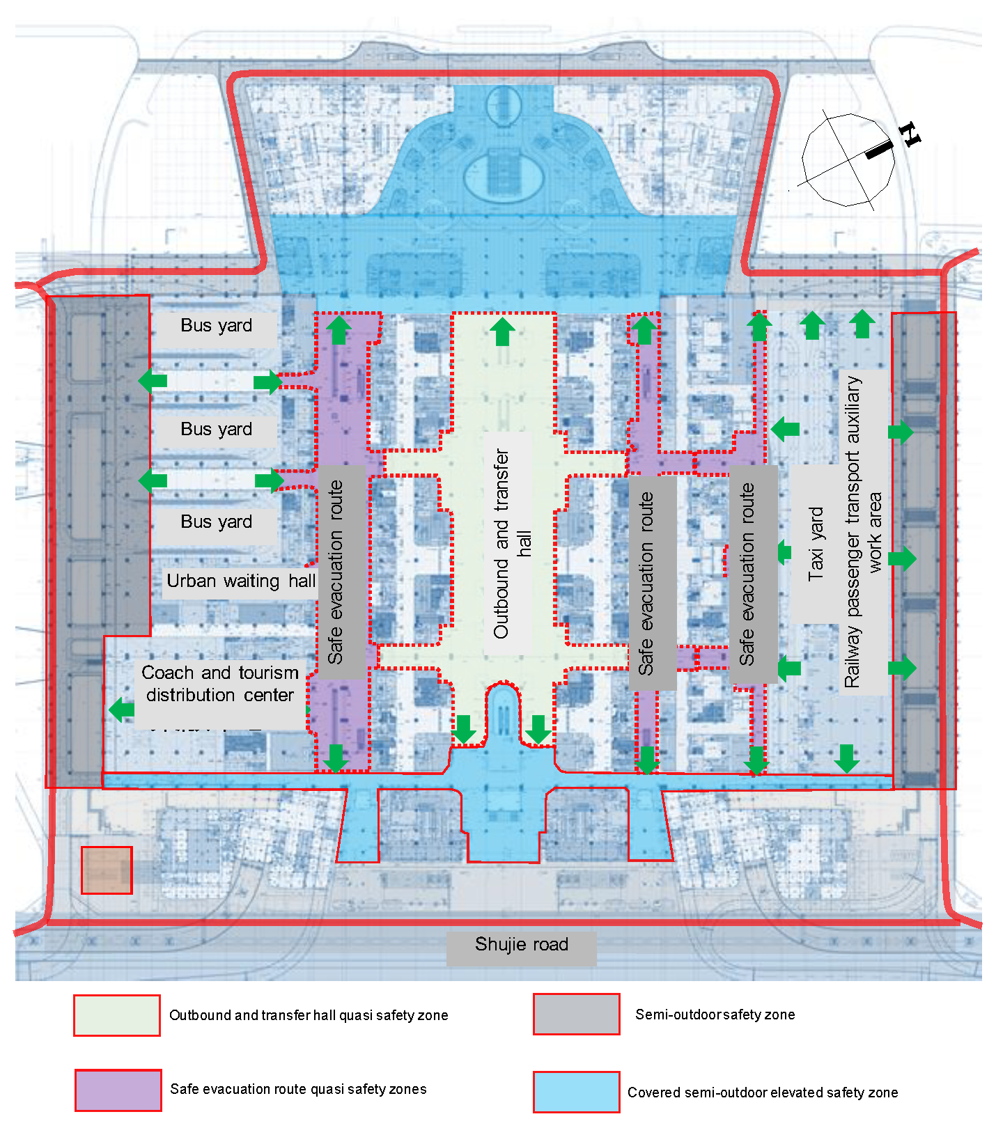
4.4.1. Outbound floor
This floor forms a circular fire lane along the outermost side. The evacuation (quasi) safety zone is constructed as follows:
(1) Semi-outdoor safety zone under the railway Bridge
On the south and north sides of this floor, there are semi-outdoor spaces under the railway bridge, which are only used as traffic lanes to meet the requirements of fire truck passing and personnel evacuation. No commercial or other high fire load facilities are established. Open openings on the top and sides, with a percentage of larger than 25%, serve as a semi-outdoor safety zone for personnel evacuation.
(2) Covered semi-outdoor elevated safety zone
On the east and west sides of this floor, there are covered semi-outdoor overhead areas, which are only used as personnel circulation and distribution areas. No non-combustible decoration is adopted inside, with open sides and good natural ventilation and convection conditions. These areas serve as semi-outdoor safety areas for personnel evacuation.
(3) Central quasi safety zone
In the middle of this floor, a safe evacuation channel and outbound transfer hall are used as a quasi safety zone for personnel evacuation. Its fire load is strictly limited to strengthen fire separation. Also, a complete fire alarm, automatic fire extinguishing and other fire protection systems are established to control fire hazards and ensure fire safety.
An evacuation system that includes functional zones (bus, coach and taxi yards, etc.), quasi safety zones (outbound and transfer halls, safety evacuation passages), semi-outdoor safety zones (semi-outdoor overhead areas), and outdoor safety zones after the above evacuation (quasi) safety zones are established on this floor.
Figure 11.
Schematic diagram of the evacuation (quasi) safe area at the outbound floor
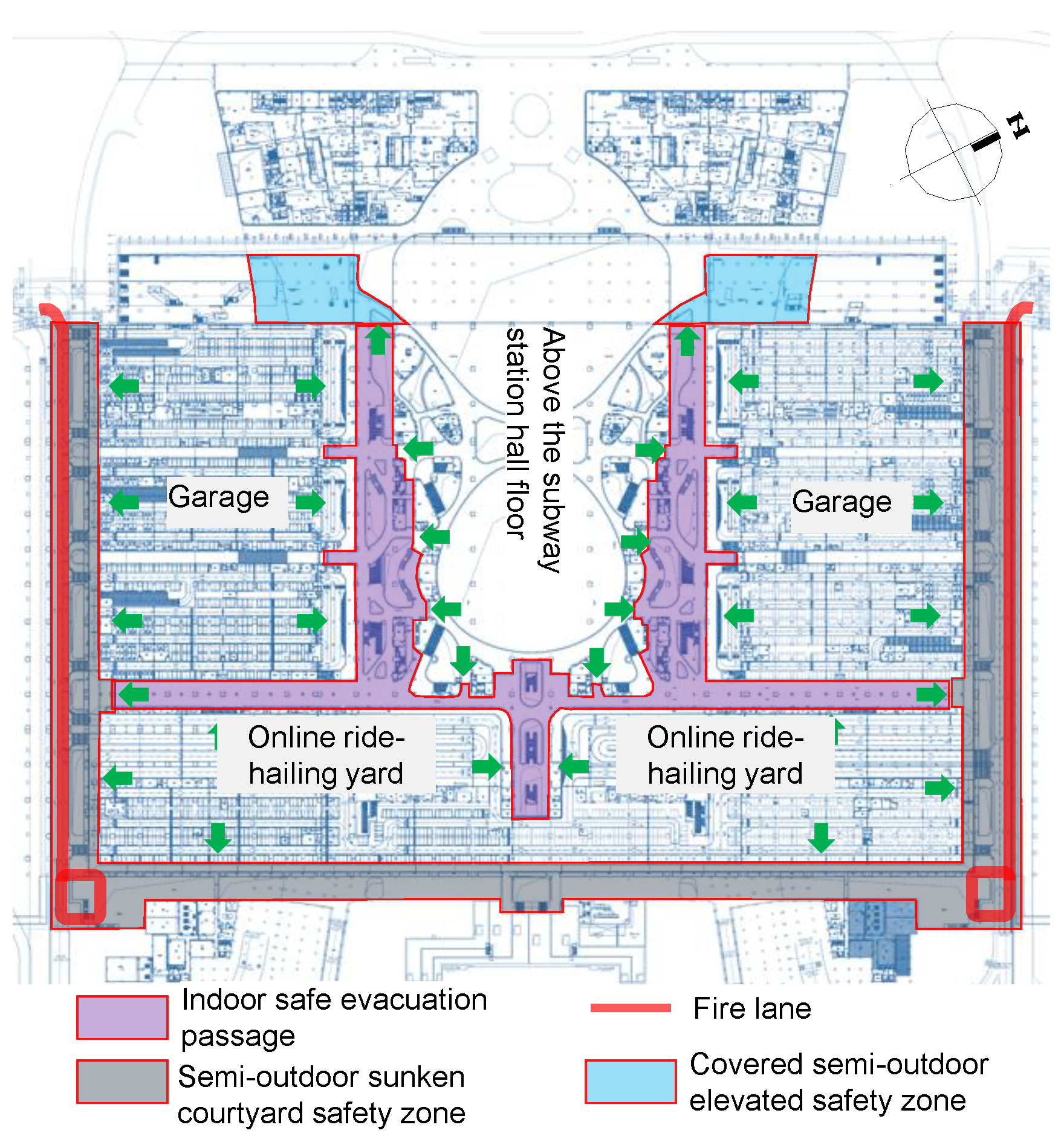
4.4.2. Comprehensive transportation and transfer floor and subway station hall floor
Two east-west end fire lanes are arranged on the south and north sides of the comprehensive transportation and transfer floor based on the sunken courtyards. The municipal Kaicheng Road and sunken courtyards are used in the subway station hall floor to establish circular fire lanes. The central and surrounding areas of these two floors are interconnected spaces, and the evacuation (quasi) safety zones constructed are basically the same and are described as follows
(1) Semi-outdoor sunken courtyard safety zone
Stepped semi-outdoor sunken courtyards are arranged on the east, south, and north sides for personnel passage and distribution. The short side is less than 13m in width, and the upper opening area, which should not be smaller than 25% of the ground area, serves as a semi-outdoor safety zone for personnel evacuation.
(2) Covered semi-outdoor elevated safety zone
The semi-outdoor elevated area of the comprehensive transportation center from an elevation of 238.00m to 249.00m on the west side is open on the side, serving as a space for personnel passage and distribution. The proportion of open openings on the top and side is greater than 25%, serving as a semi-outdoor safety zone for personnel evacuation.
(3) Central quasi safety zone
In the central part of this floor, the public corridor between the garage area and the public area of the subway station hall serves as a quasi safety zone for personnel evacuation. Its fire load is strictly limited to strengthen fire separation and a complete system, including fire alarm, automatic fire extinguishing and other fire protection systems, are provided to control fire hazards and ensure fire safety.
Figure 12.
Schematic diagram of the evacuation (quasi) safety zone on the hall floor of a subway station.
Figure 12.
Schematic diagram of the evacuation (quasi) safety zone on the hall floor of a subway station.
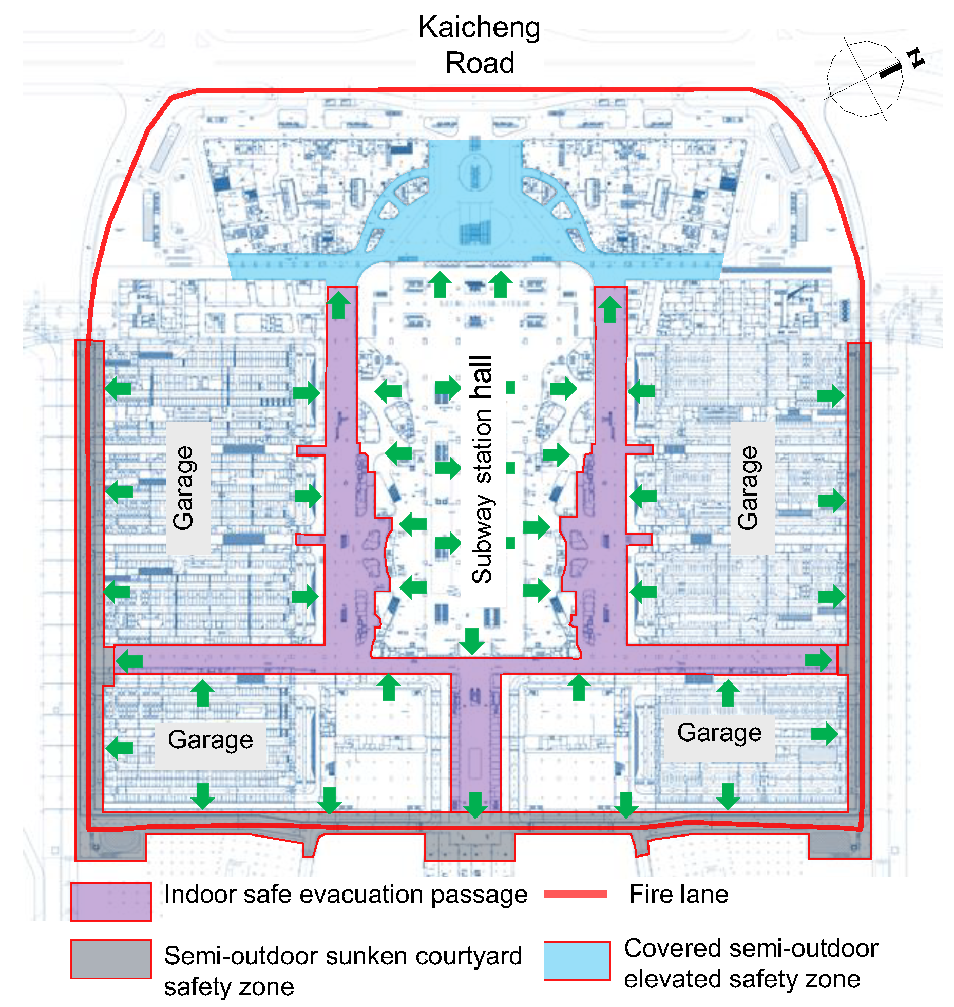
Figure 13.
Schematic diagram of the evacuation (quasi) safety zone at the comprehensive traffic transfer floor.
Figure 13.
Schematic diagram of the evacuation (quasi) safety zone at the comprehensive traffic transfer floor.
An evacuation system that includes functional zones (bus, coach and taxi yards, etc.), quasi safety zones (safety evacuation passages), semi-outdoor safety zones (semi-outdoor sunken courtyards, overhead areas), and outdoor safety zones after the above evacuation (quasi) safety zones are established on the comprehensive transportation and transfer floor and the subway station hall floor.
5. Fire safety validation analysis
In accordance with the principles and methods of fire safety engineering, a fire dynamics model and a personnel evacuation model were established for Chongqing East Station, as shown in Figure 14.
By setting multiple sets of fire scenarios and personnel evacuation scenarios in different zones, the time of arrival in case of fire hazards and the time required for personnel evacuation under fire conditions were compared to obtain the results of personnel safety assessment, as shown in Table 3.
6. Conclusion
The fire safety of the design scheme of Chongqing East Station was verified through numerical simulation by constructing fire scenarios, and personnel evacuation scenarios. The simulation analysis results show that the available evacuation time (ASET) of personnel in each fire scenario is longer than the required evacuation time (RSET), thus ensuring safe personnel evacuation.
Therefore, the fire protection design plan of Chongqing East Station can meet the expected fire safety goals, achieve safe evacuation of personnel and rapid execution of fire rescue tasks, and guarantee the safety of personnel's lives and property. Its fire protection design standard should not be lower than the equivalent fire safety level specified in the technical standards for fire protection in national engineering construction.
Station-city integration represents a new mode of railway engineering development and a new form of station building. It is difficult for traditional technical standards to adapt to this type of building. Due to space limitations, this paper only analyzes the macro fire protection design scheme of Chongqing East Station, without fully presenting the design details. Moreover, there is still room for further research on multi-functional integration interface fire separation, multi-property interface management, external fire rescue mode, and linkage control mechanism.
References
- Liang, Y.; Song, W.; Dong, X. Evaluating the Space Use of Large Railway Hub Station Areas in Beijing toward Integrated Station-City Development. Land 2021, 10, 1267. [Google Scholar] [CrossRef]
- Yue, Y. , & Chang, J. (2021). Station-City Integration: Urban Space Ecological Transformation Research Based on Rail Transit. Human-Centered Urban Planning and Design in China: Volume II: Urban Design and Mobility, 41-64. [CrossRef]
- Tao, S.; Xie, X. Evaluation of Transfer System of High-Speed Railway Station Based on the Integration of Station City. Sixth International Conference on Transportation Engineering. LOCATION OF CONFERENCE, ChinaDATE OF CONFERENCE;
- Vale, D.S. Transit-oriented development, integration of land use and transport, and pedestrian accessibility: Combining node-place model with pedestrian shed ratio to evaluate and classify station areas in Lisbon. J. Transp. Geogr. 2015, 45, 70–80. [Google Scholar] [CrossRef]
- Yang, H.; Li, S.-C. Numerical Investigation on the Effect of Mobile Smoke Ventilator on Fire-induced Smoke Extraction for Underground Platform in a High-speed Railway Station. Procedia Eng. 2018, 211, 871–880. [Google Scholar] [CrossRef]
- Yang, H.; Yuen, R.K.; Zhang, H.P. Numerical Study of Smoke Control for Underground Platform in a High-Speed Railway Station. Appl. Mech. Mater. 2012, 256-259, 2803–2812. [Google Scholar] [CrossRef]
- Dong C, Guo C, Yang K. TOD Evacuation simulation model and implementation[C]//2019 9th International conference on fire science and fire protection engineering (ICFSFPE). IEEE, 2019: 1-4.
- Ku, C. Y. , W. K., & Yue, T. K. (2020). Fire evacuation in a large railway interchange station. In The Proceedings of 11th Asia-Oceania Symposium on Fire Science and Technology 11th (pp.; pp. 225–239. [CrossRef]
- Salarian, A.H.; Mashhadizadeh, A.; Bagheri, M. Simulating Passenger Evacuation in Railway Station under Fire Emergency using Safe Zone Approach. Transp. Res. Rec. J. Transp. Res. Board 2020, 2674, 806–812. [Google Scholar] [CrossRef]
Figure 1.
General layout of Chongqing East Station
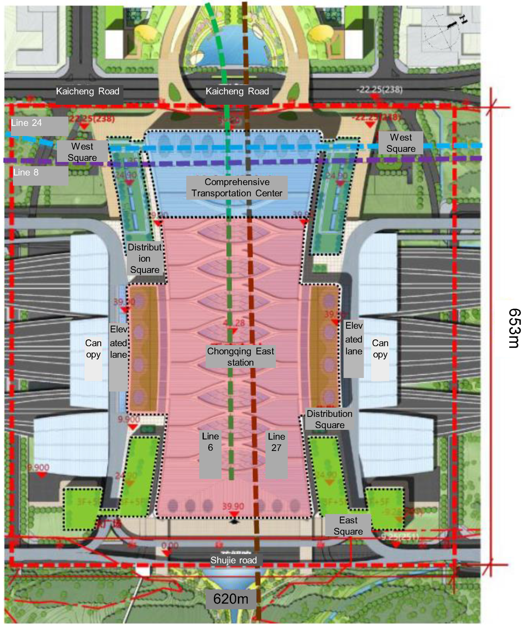
Figure 2.
Sectional view of each floor of Chongqing East Station
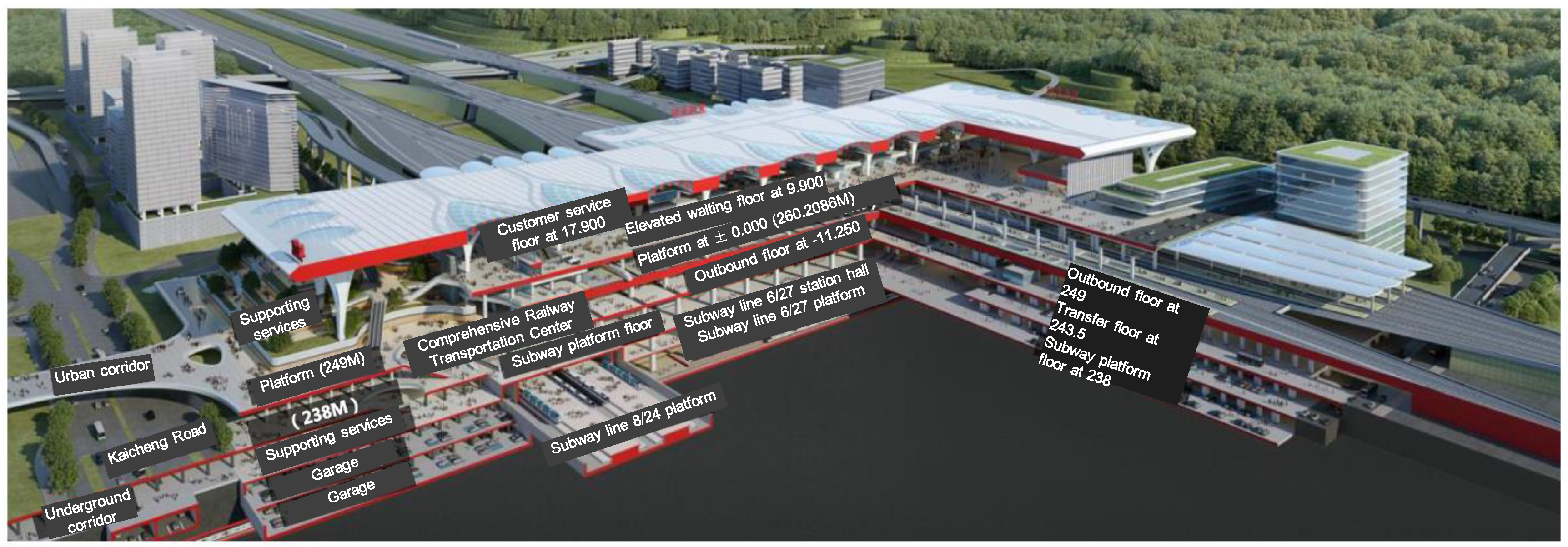
Figure 3.
Layout plan of multi-storey fire lanes in Chongqing East Station
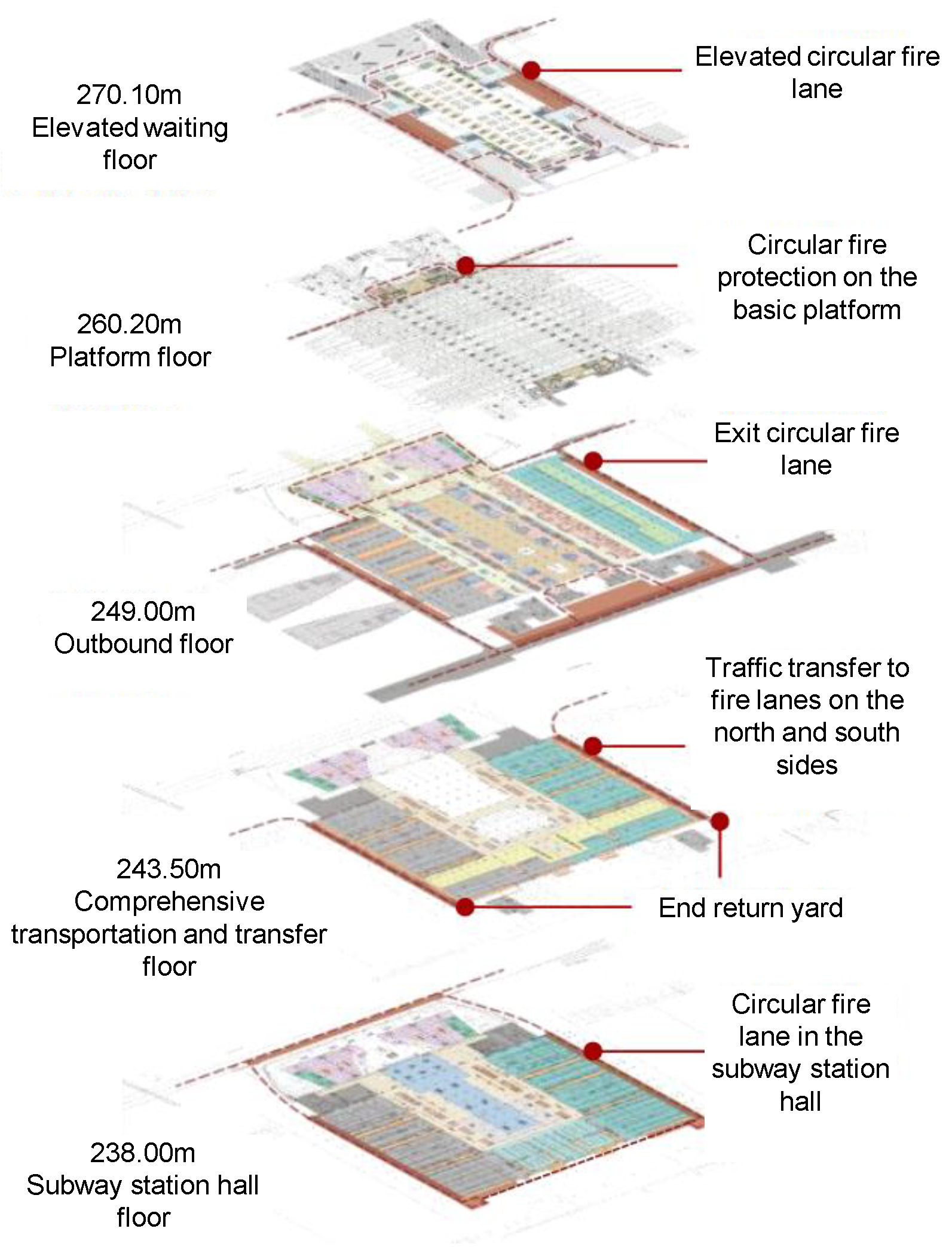
Figure 4.
Layout plan of outbound floor
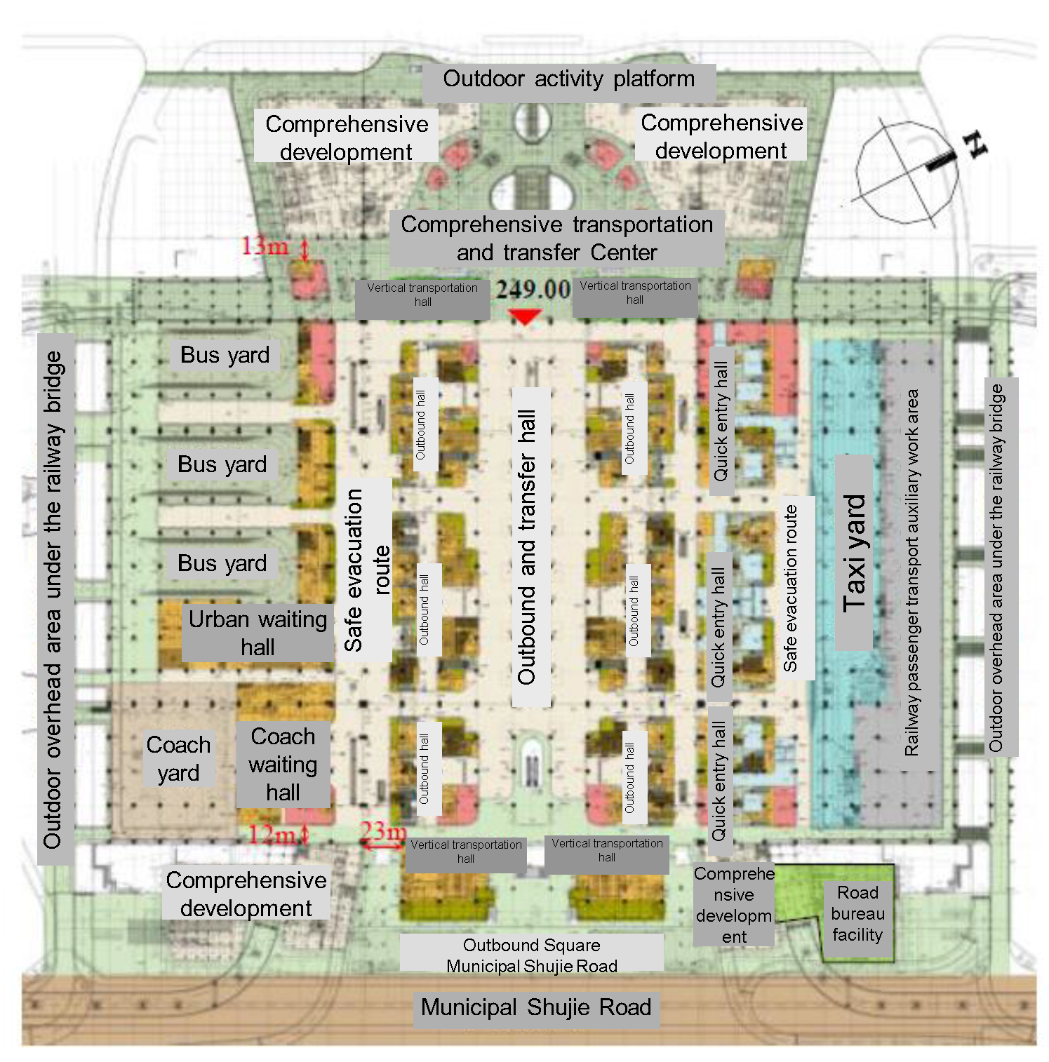
Figure 14.
3D model of fire smoke and evacuation
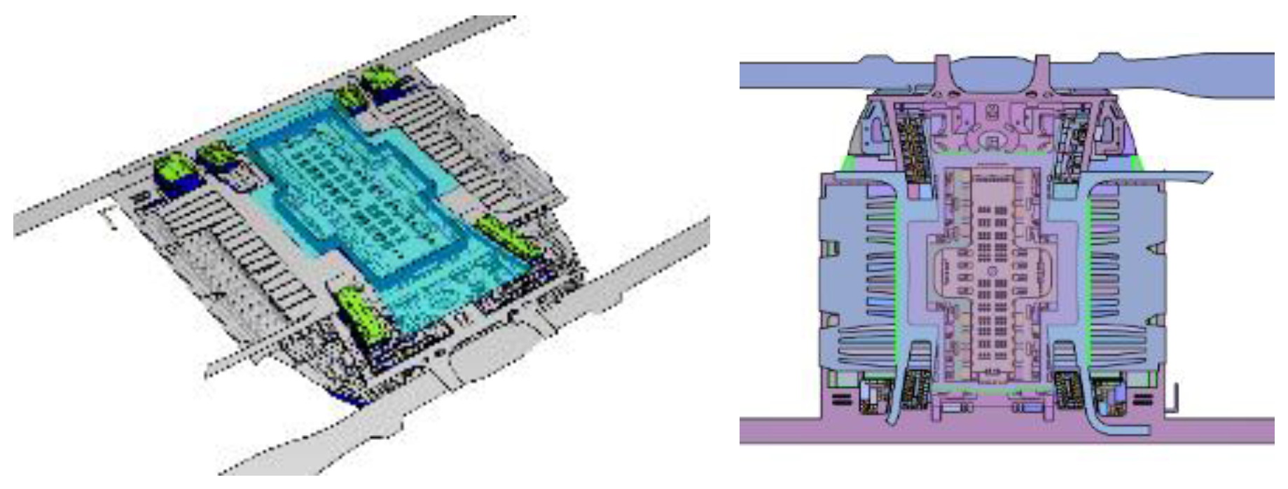

Table 1.
Elevation and function distribution of each floor
| No. | Main building level | Elevation | Functions |
| 1 | Elevated travel service mezzanine | 278.10m | Travel service business |
| 2 | Elevated waiting floor | 270.10m | Elevated entrance and waiting areas |
| 3 | Platform floor | 260.20m | Station yard and entrance distribution hall |
| 4 | Outbound floor | 249.00m | Outbound hall, bus and coach yards |
| 5 | Comprehensive transportation and transfer floor | 243.50m | Comprehensive transportation supporting garage Shared subway station hall |
| 6 | Subway station hall floor | 238.00m | |
| 7 | Subway transfer hall | 231.10m | Platform for Line 8/24 |
| 229.30m | Subway transfer hall | ||
| 8 | Subway platform floor | 222.10m | Transfer passage and entrance/outbound hall |
| 220.60m | Platform for Line 6/27 |
Table 2.
Statistical table of the area of each area in the super large fire compartment
| No. | Building level | Elevation | Area (m2) |
| 1 | Elevated travel service mezzanine | 278.10m | 31243 |
| 2 | Elevated waiting floor | 270.10m | 68500 |
| 3 | Platform floor | 260.20m | 4155 |
| 4 | Outbound floor | 249.00m | 4192 |
Table 3.
Judgment table for personnel evacuation safety under fire conditions
| Fire scenario | Fire location | Region | ASET (s) |
RSET (s) |
Is it safe | |
| 1 | Elevated floor | Restaurant establishment fire on the Waiting Hall Mezzanine | Waiting hall | >1200 | 755 | √ |
| 2 | Luggage fire in the waiting hall | Waiting hall | >1200 | 827 | √ | |
| 5 | Store fire in the Waiting Hall | Waiting hall | >1200 | 827 | √ | |
| 3 | Platform floor | Luggage fire on the west platform | West platform | >1800 | 339 | √ |
| 4 | Outbound floor | Luggage fire in the western semi-outdoor overhead area | Western semi-outdoor overhead area | >1200 | 864 | √ |
| 5 | Bus fire under the southern railway bridge | Semi-outdoor overhead area under the railway bridge on the south side | >1800 | 702 | √ | |
| 6 | Luggage fire in the outbound and transfer hall | Outbound and transfer hall | >1200 | 456 | √ | |
| 7 | Restaurant establishment fire on the safety evacuation passage | Safety evacuation passage on the south side | 830 | 686 | √ | |
| 8 | Subway station hall floor | Luggage fire in the western semi-outdoor overhead area | Western semi-outdoor overhead area | >1800 | 1386 | √ |
| 9 | Fire in the travel service room of the safety exit | Safe evacuation passage at the subway station hall floor | >1200 | 932 | √ | |
| Safe evacuation passage on the comprehensive transportation and transfer floor | 746 | 696 | √ | |||
| 10 | Car fire in the sunken courtyard on the south side | Semi-outdoor sunken courtyard on the south side | >1800 | 1476 | √ | |
Disclaimer/Publisher’s Note: The statements, opinions and data contained in all publications are solely those of the individual author(s) and contributor(s) and not of MDPI and/or the editor(s). MDPI and/or the editor(s) disclaim responsibility for any injury to people or property resulting from any ideas, methods, instructions or products referred to in the content. |
© 2023 by the authors. Licensee MDPI, Basel, Switzerland. This article is an open access article distributed under the terms and conditions of the Creative Commons Attribution (CC BY) license (https://creativecommons.org/licenses/by/4.0/).
Copyright: This open access article is published under a Creative Commons CC BY 4.0 license, which permit the free download, distribution, and reuse, provided that the author and preprint are cited in any reuse.


