1. Introduction
Composite in construction industry is a word that refers to the usage of steel, reinforced concrete, and composite steel-concrete components in combination with one another. Mixed or hybrid systems are a contemporary trend in the building sector. These structures maximize the structural and economic advantages of each component type by optimizing their usage. A thorough research is presently being performed to have a better grasp of how such frames operate. On the other hand, beam-columns combination has long been known for their better earthquake protection and has become a popular building method. In light of the growing popularity and usage of such systems, frame analysis is required. Additionally, since nonlinear analysis is a strong tool for better understanding system behaviour, especially when dynamic excitation occurs. Available analytic programs are capable of simulating behaviour of typical steel or composite structures. In the past, powerful earthquakes have caused major property damage and fatalities. Earthquake damage is primarily related with seismically weak buildings, which were frequently constructed prior to the adoption of modern building rules. As a result, academics have concentrated their efforts on discovering novel and effective ways for mitigating seismic risk in such structures. Direct-integration THA is a nonlinear, dynamic analysis method in which the structure is subjected to seismic load varying with respect to time and the equilibrium equations of motion are integrated fully to get the response of the structure. This is done by integrating structural characteristics and behaviours for successive time steps that are very short compared to the seismic excitation period. The equation of motion used in this method is
Pushover analysis is a nonlinear static approach in which a predetermined pattern gradually increases the magnitude of structural loads along the lateral direction of the structure. The behaviour of the structure is generally believed to be governed by its fundamental mode, and the predefined pattern is expressed in either storey shear or fundamental mode shape. The displacement control raises the displacement of the building's top storey such that the building is subjected to the required level of horizontal load. The distance to which structure is pushed is proportional to its fundamental horizontal mode of translation. In both kinds of pushover analysis, the structure's stiffness matrix may need to be changed for each increase in load or displacement when it changes from elastic to inelastic. Usually, the displacement-controlled pushover analysis is favoured over the force-controlled pushover analysis as the research may be performed to the desired level of displacement.
A number of research works have been carried out in the field of seismic analysis of steel and composite frames and effects of various parameters on the seismic behaviour of structure is hence known. Inelastic behavior of frames is well possible with respect to performance based design [
1]. Hence we can access response-based damage of structures more effectively [
2]. Chopra [
3] provided comparing response of SDF Systems to Near-Fault and Far-Fault Earthquake Motions in the Context of Spectral Regions. For inelastic structures displacement based seismic design procedure is also available which can be more effectively used [
4]. Some light is also put on correlation study between seismic acceleration parameters and damage indices of structures [
5]. Indian design codes also given provision for analysis and design of such structures [
6,
7,
8]. For more effective design and analysis cross-sectional properties of complex composite beams needs to be obtained [
9]. Friction-tuned mass damper can also be used to statistical linearization of such frames [
10]. Further we obtain some literature on assessment of minimally compliant low-rise base isolated and conventional steel moment resisting frame buildings [
11]. Different types of bracings are required to improve the performance of ductile frames [
12]. Performance based design approach is more useful for better estimation of forces and design of structural elements [
13,
14,
15,
16]. Also optimum positioning of shear walls is also treated as remedial measures to mitigate the effects of lateral forces in building frames [
17]. We can investigate the in-plane flexibility of steel-deck composite floors in steel structures for more effective design approach [
18]. Connections plays major role in performance assessment of steel frames [
19]. Experimental, analytical and numerical estimation is required for composite frames [
20]. Seismic Fragility of Buildings under earthquake impact is necessary to better understanding the forces [
21].
2. Methodology and structural description
In this study two G+10 storey frames, steel and a composite frame is considered for comparison. Both frames are having a floor-to-floor height of 3m and three bays of 5m each in both directions of plan. The supports are fixed at base and resting on Type-II (Medium) soil. A damping of 5% and importance factor of 1 is assumed. Modal analysis, response spectrum analysis and push over analysis are performed to access the vulnerability of building frames. Direct integration time history analysis is also performed for the comparison of the results.
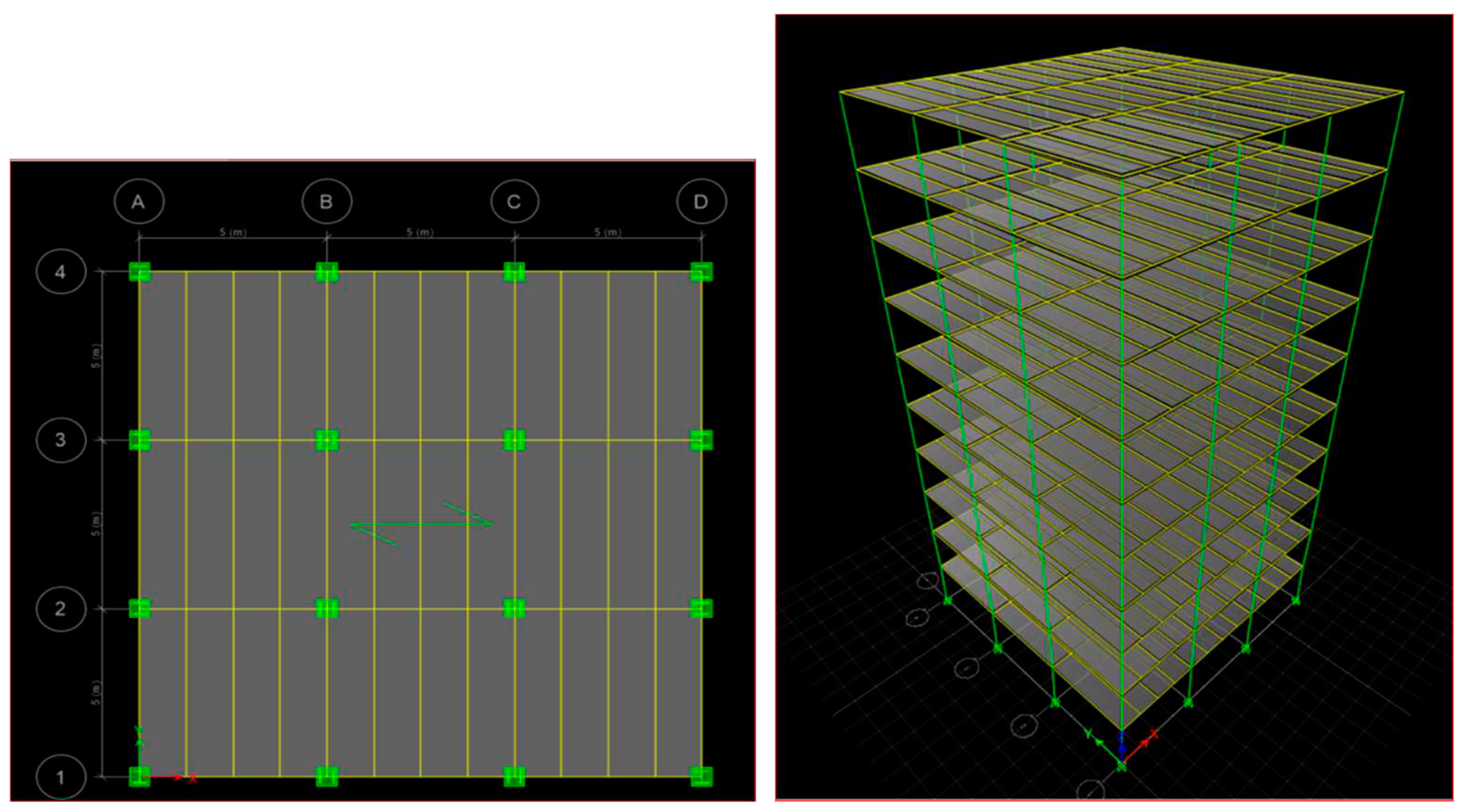
For columns structural steel Fe345, for beams structural steel Fe250, concrete of grade M30, rebars of grade Fe415, deck slab material Fe250 and shear studs of grade Fu400 have been used. The plan and 3-Dimensional view of the completed model is shown in
Figure 1. The types of sections used in the study are shown in
Figure 2. Encased column section is used in composite frame and hot rolled steel section is used as column in steel frame. For both frames hot rolled steel sections are used for primary and secondary beams. Deck slab assembly with shear studs are used in both frames. All the sections are designed to have the same plastic moment capacity. For all sections other than composite column the following equation is used to calculate plastic moment capacity
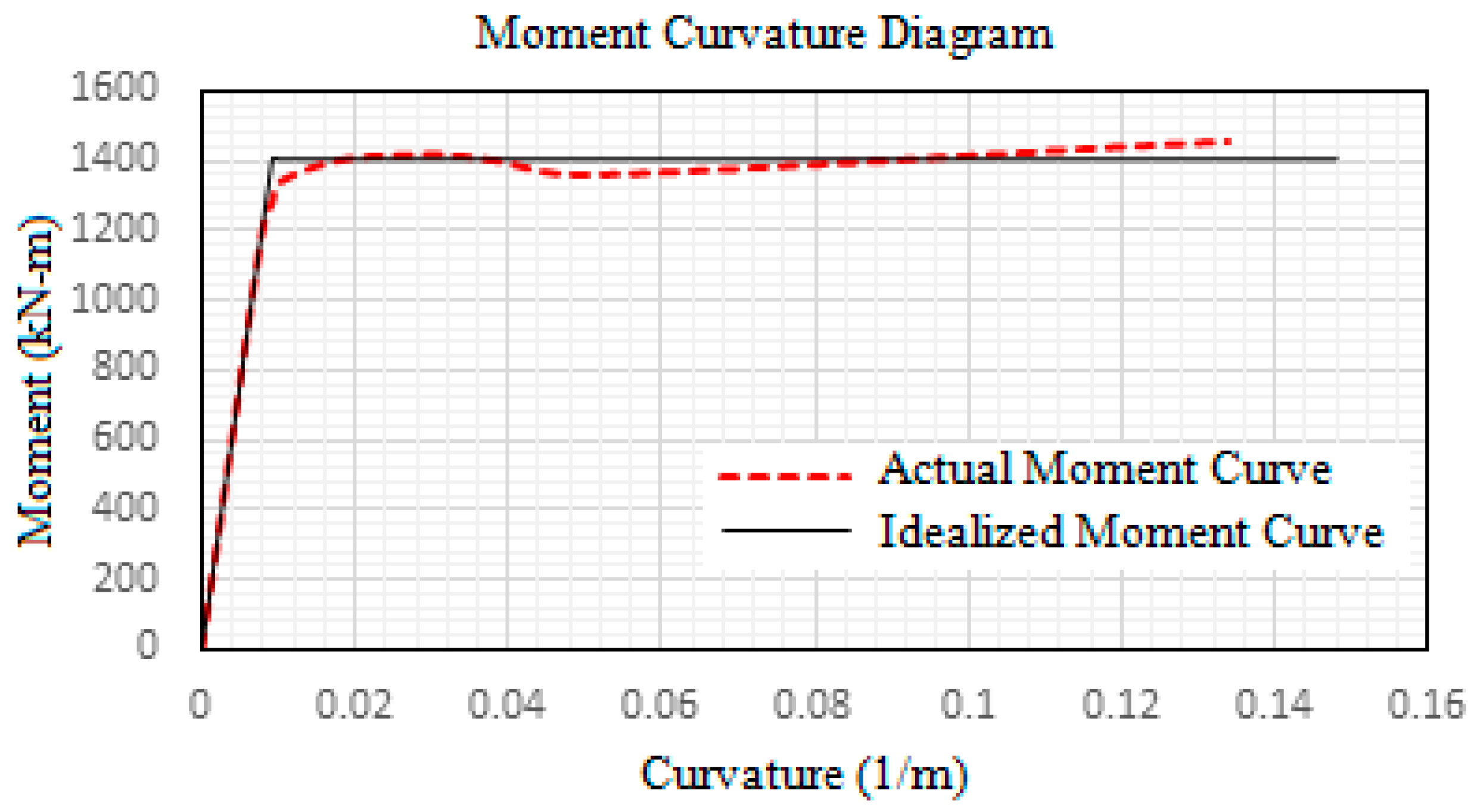
where, Zp is plastic section modulus and fy is yield stress of the material. For, composite column the SAP2000 design modeller has been used to calculate the plastic moment capacity by Caltrans idealization of M-ϕ (Moment-curvature) curve.
3. Load details and design sections
The dead, live and seismic loads were assumed as per IS 875: Part 1, 2:1987 and IS 1893: Part1:2002. Self-weight, an imposed load of 2.5kN/m2, floor finish of 1.5kN/m2, roof live load of 1.5kN/m2 and wall load of 6kN/m (Brick density = 22kN/m2) is applied on the frames. For equivalent static analysis seismic zone factor 0.36, Site type-II, importance factor 1, response reduction factor 5 and damping of 5% have been assumed. Fourteen load combinations are considered in the design in accordance with IS 1893:2016. The steel frame design is done in accordance with IS 800:2007, composite beam design in accordance with AISC 360-16 and composite column design in accordance with AISC 360-10. The sections are chosen such that the plastic moment capacities are same for both steel and composite frame. The load combinations considered are:
The plastic moment capacity of sections after design is given in
Table 1
The ‘Mp’ for Composite column was calculated by Caltrans idealization of M-ϕ curve with the aid of SAP2000 design modeller.
Figure 3. shows the actual M-ϕ curve and Idealized M-ϕ curve obtained from SAP2000 section design modeller. The final sections after static analysis and design in Etabs are WPB 300x300 for steel column, WPB 360x370 encased 540x540mm M30 concrete with 25mm dia bars at corners and 12mm dia lateral ties with clear cover 40mm for composite column, ISWB 300 for primary beams and ISLB 225 for secondary beam. For deck slab 1mm thick membrane filled with M30 concrete with slab depth of 110mm and rib depth 75mm. 6 shear studs with height 150mm and 19mm dia is provided on all secondary beams.
4. Results and discussions
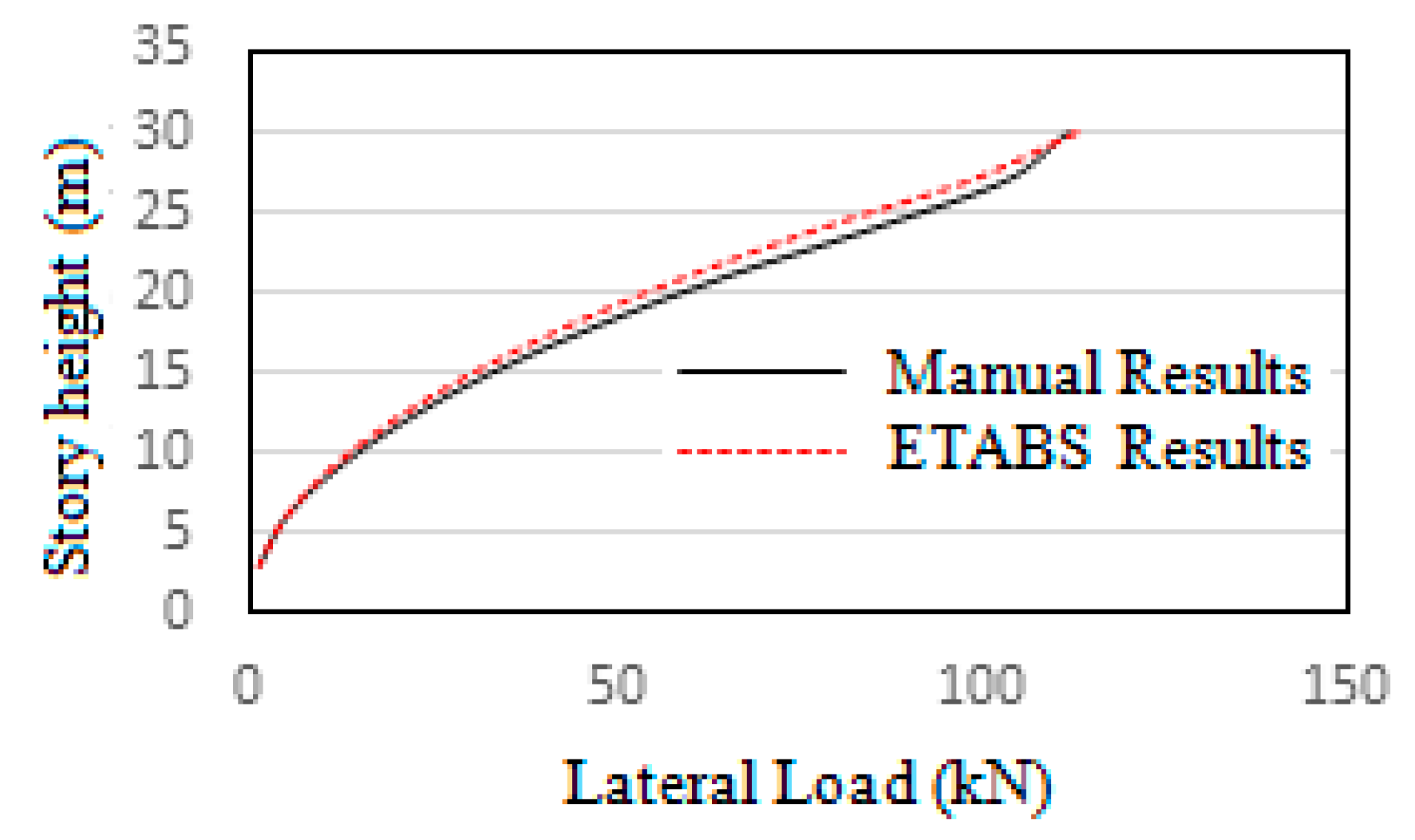
After the static analysis and design of the frames in Etabs, the model has been validated by comparing the manually calculated result and software result of lateral load distribution along the height of the steel frame. The seismic coefficient method has been used as per IS 1893:2002 to do the validation. The results showed only a slight variation of 6%. The validation result is shown in
Figure 4. The values are given
Table 2.
Modal analysis
The model in this study does not consider the effects of shear walls, lift well, infill wall effects and other non-structural elements in the design. Moreover, the sections chosen are larger than the least sections required in optimum design. This is owing to the criteria for comparison of the frames keeping the plastic moment capacity of the assumed sections same. The column size has been kept constant throughout the building height which has further increased the design section and overall mass of the frame. Also, the loads applied and influence of stiffness of floor slabs also affects the time period. Considering all these factors the time period of the modelled frames is a little higher than usual 10 story buildings. The time periods of the first three modes are given in
Table 3. Modal analysis has been performed via Ritz analysis method in Etabs as it provides better results for time history analysis. The natural frequencies obtained for steel and composite frames are 0.40Hz and 0.44Hz respectively.
Response Spectrum Analysis
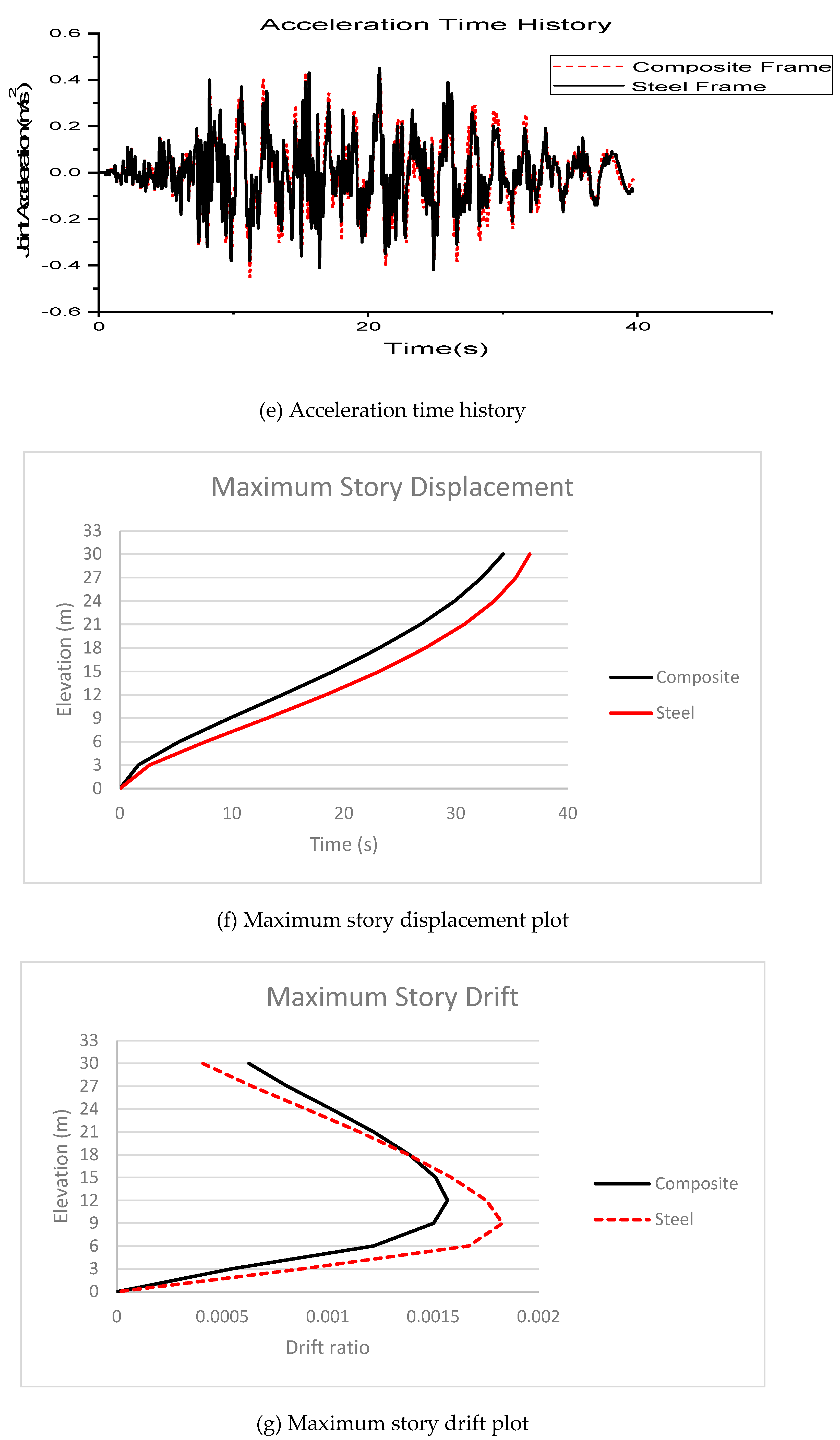
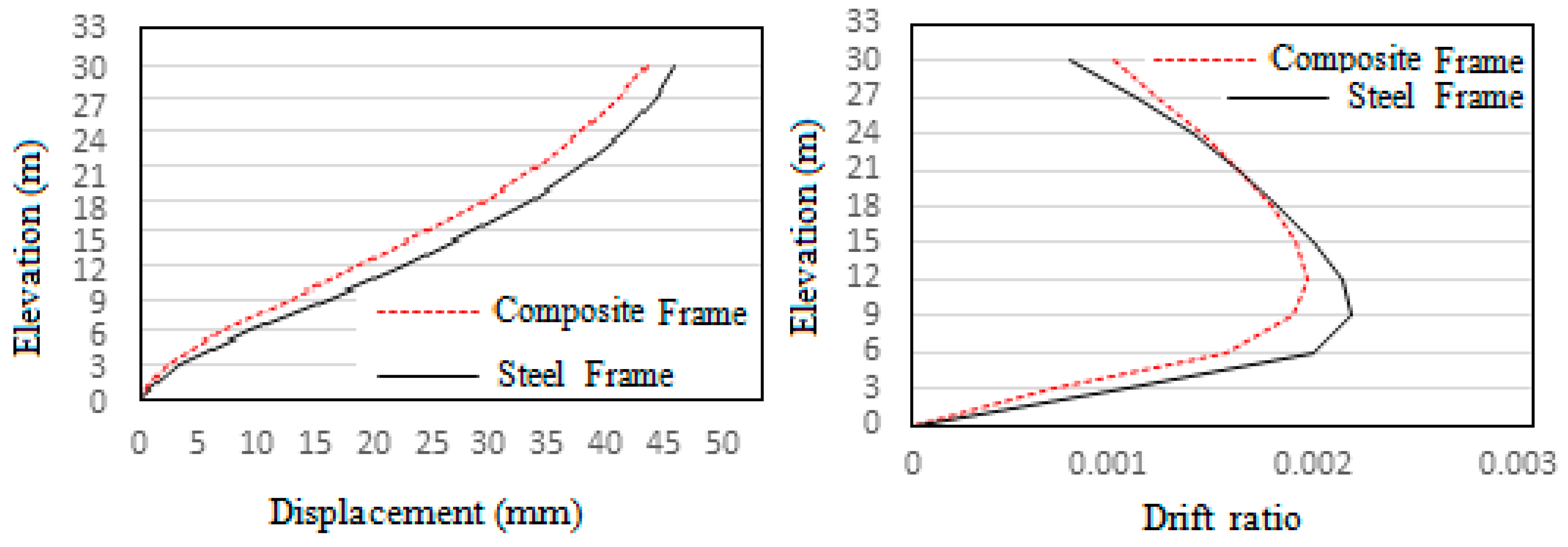
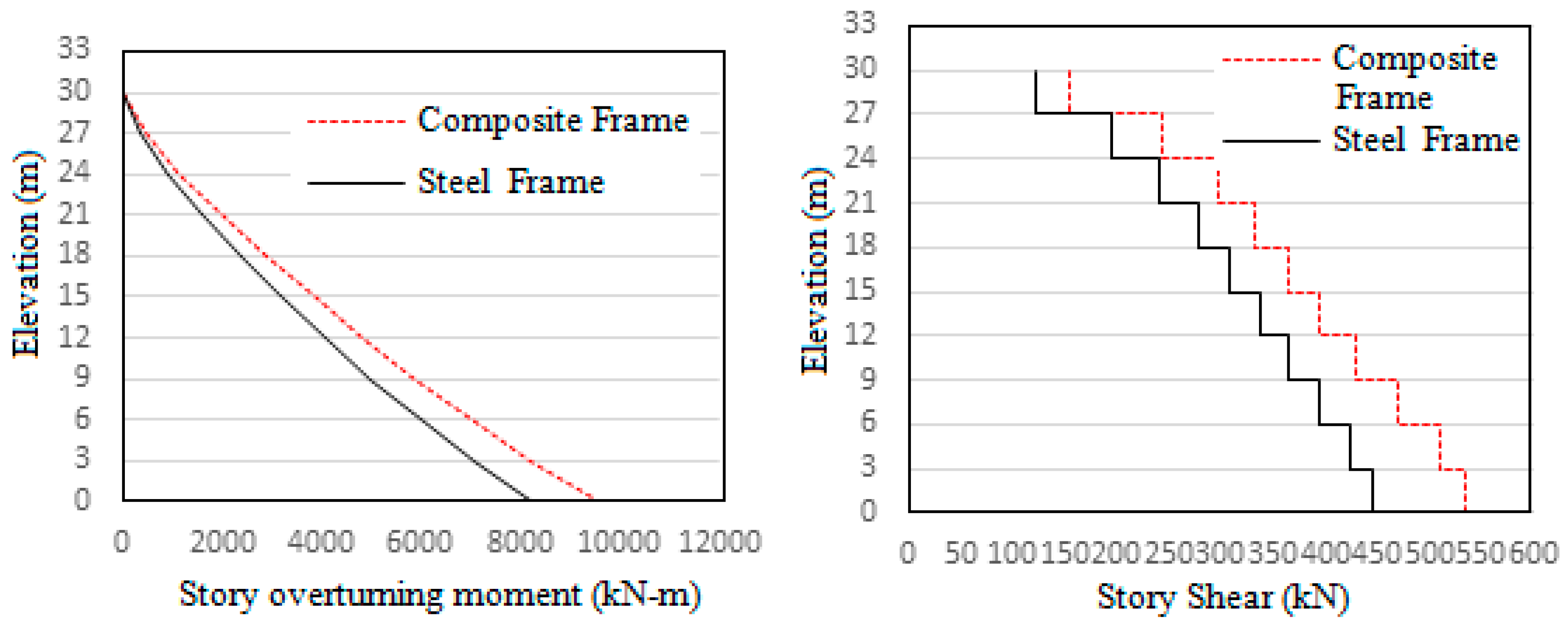
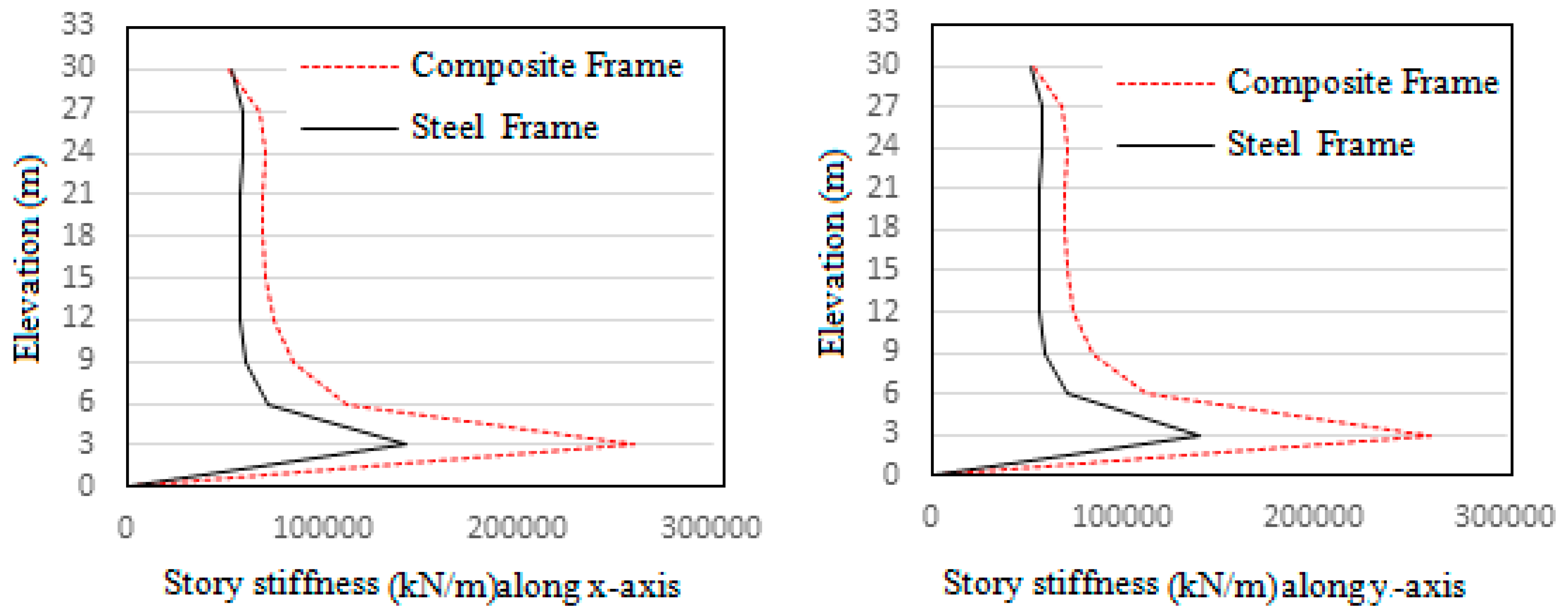
Response spectrum analysis were done for both steel and composite frames in both x and y directions as per IS 1893:2002 for 5% damping, Soil type II and seismic zone V. The responses obtained in both directions are similar due to the symmetric configuration of the frames. The comparison of story displacement, story drift, overturning moment, story shear and story stiffness are shown in
Figure 5,
Figure 6 and
Figure 7. The values obtained for maximum top story displacement and story drift are greater for steel frame. Base shear, story overturning moments and story stiffness values are greater for composite frame. The greater base shear and overturning moments of composite frame is due to its greater mass. Its lower story drift and displacements are due to better stiffness. The maximum responses of steel and composite frames after response spectrum analysis are given in
Table 4.
Pushover Analysis
Since the behaviour of the frames are similar in both directions as evident from the response spectrum analysis due to symmetric configuration of the frames, pushover analysis is performed only for horizontal x-direction. Auto hinges were assigned as per AISC 41-13 to both ends of structural members at relative distance of 0.1 and 0.9 respectively. M3 (Flexural) hinges were assigned to beams and P-M2-M3 (Coupled axial and Biaxial bending) hinges were assigned to the columns. Displacement coefficient method was done as per AISC 41-13 to get the target/maximum displacement by using modification coefficients to peak elastic displacement. The pushover curve is used to determine effective stiffness and period, and when used with a response spectrum gives the spectral acceleration. The spectral acceleration is converted into elastic displacement to which coefficients are applied to determine the target displacement. It uses the relation:
Where, Co is a factor to relate the spectral displacement of the equivalent SDoF and building roof displacement, C1 is a modification factor relating expected maximum inelastic displacements to displacements calculated for linear elastic response, C2 is a modification factor to represent the effect of hysteresis shape on the maximum displacement response, Sa is the spectral acceleration at the effective period and damping ratio of the building in the direction under consideration, Te is the effective period of the building in the direction under consideration and g is acceleration due to gravity. Capacity spectrum method was done as per FEMA 440 Equivalent linearization to get the performance point by overlapping capacity spectrum and the design spectrum. A control displacement of 700mm was applied to the top story joint label 1. P-Delta geometric nonlinearity was also considered in the analysis.
For steel frame push-x was run in the steel frame and the following are the results obtained.
Table 5 represents the pushover details in each of the steps.
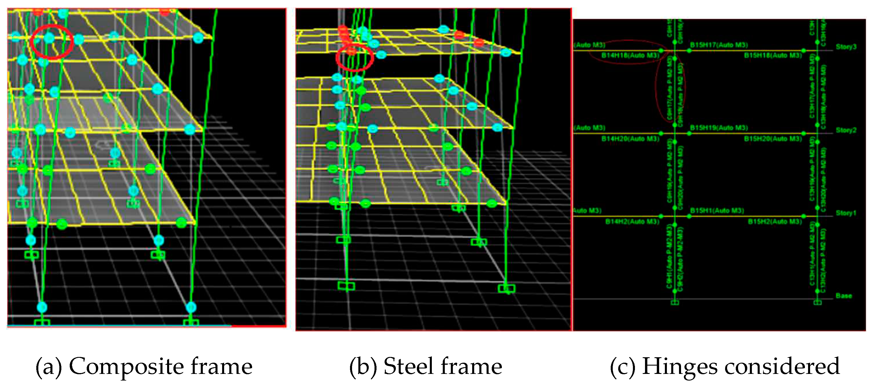
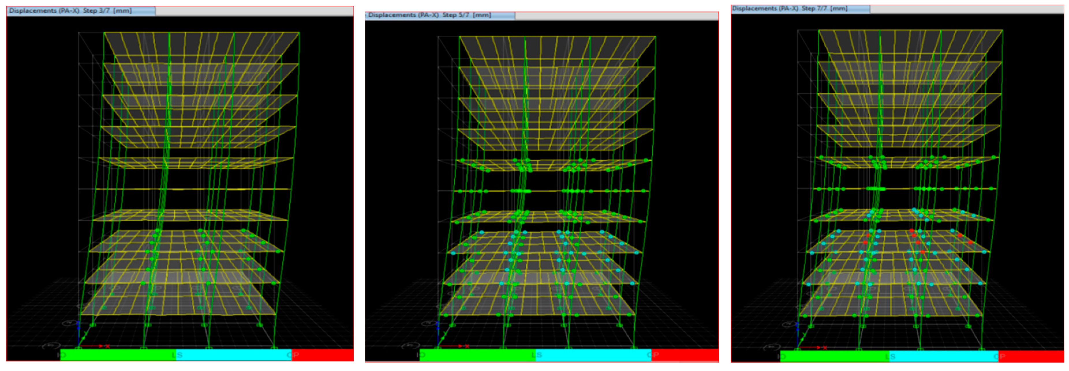
Figure 8 shows the formation of different safety levels of hinge formation across the pushover analysis. The different safety levels are Intermediate occupancy (IO), Life safety (LS) and Collapse prevention (CP). IO hinges are shown in green color, LS hinges are shown in light blue color and CP hinges are shown in red color.
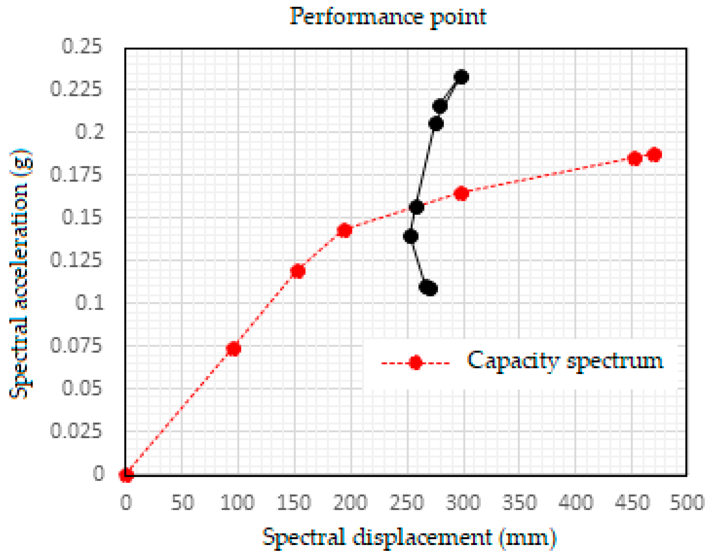
To obtain the performance point of steel frame the IS 1893:2002 for design based earthquake was used in capacity spectrum method. A Damping ratio of 0.05 and scale factor of ‘g’ (acceleration due to gravity) is assumed. The IS design spectrum represented in terms of Spectral acceleration vs Time period is converted to Acceleration displacement response spectrum (ADRS) in terms of Spectral acceleration vs Spectral displacement. Then the ADRS curve is overlapped with the capacity curve obtained from pushover analysis to get the required performance point. This gives the performance point of the steel frame for the given site details.
The graph showing performance point is illustrated in
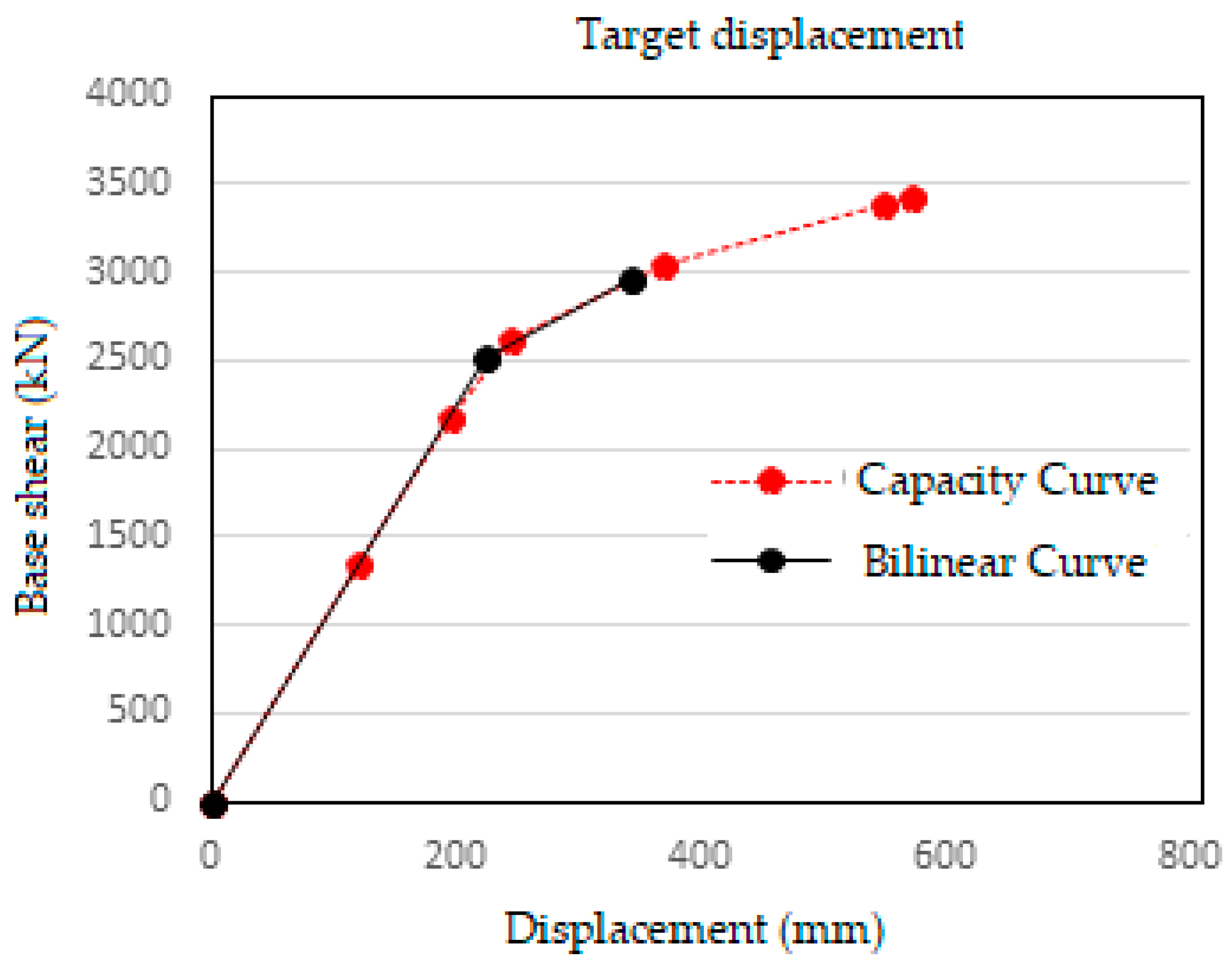
Figure 9. The target displacement calculated according to ASCE 41-13 is shown in
Figure 10.
Composite frame Push-x was run in the composite frame and the following are the results obtained.
Table 6 represents the pushover details in each of the steps.
We shows the formation of different safety levels of hinge formation across the pushover analysis. The different safety levels are Intermediate occupancy (IO), Life safety (LS) and Collapse prevention (CP). IO hinges are shown in green color, LS hinges are shown in light blue color and CP hinges are shown in red color.
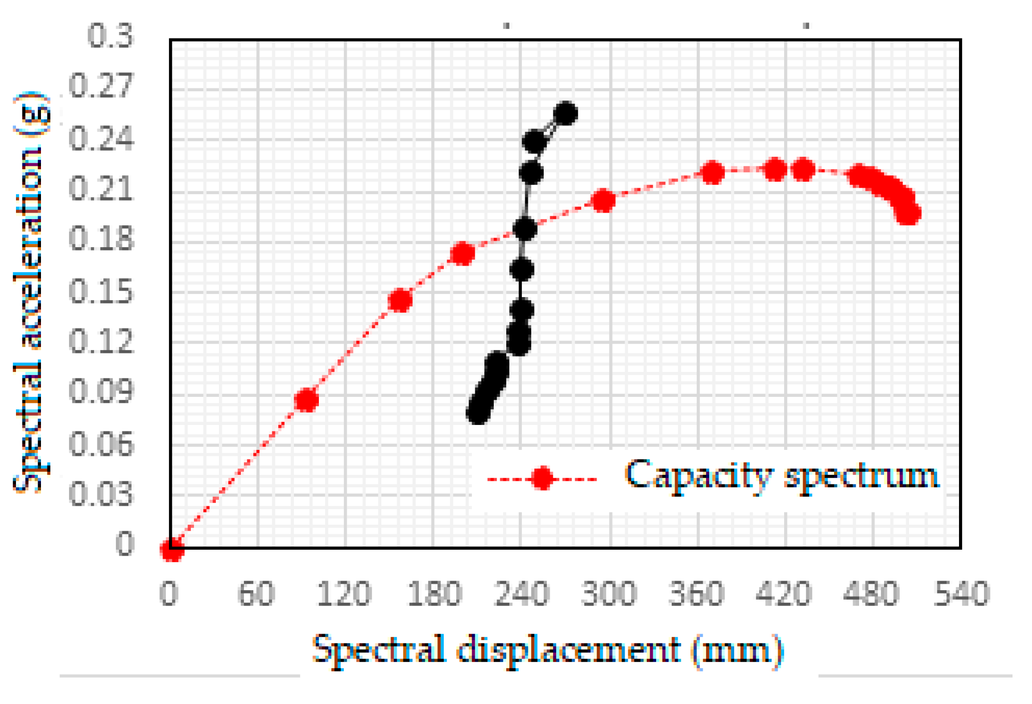
The performance point and target displacement is found out through same steps as before. The graph showing performance point is illustrated in
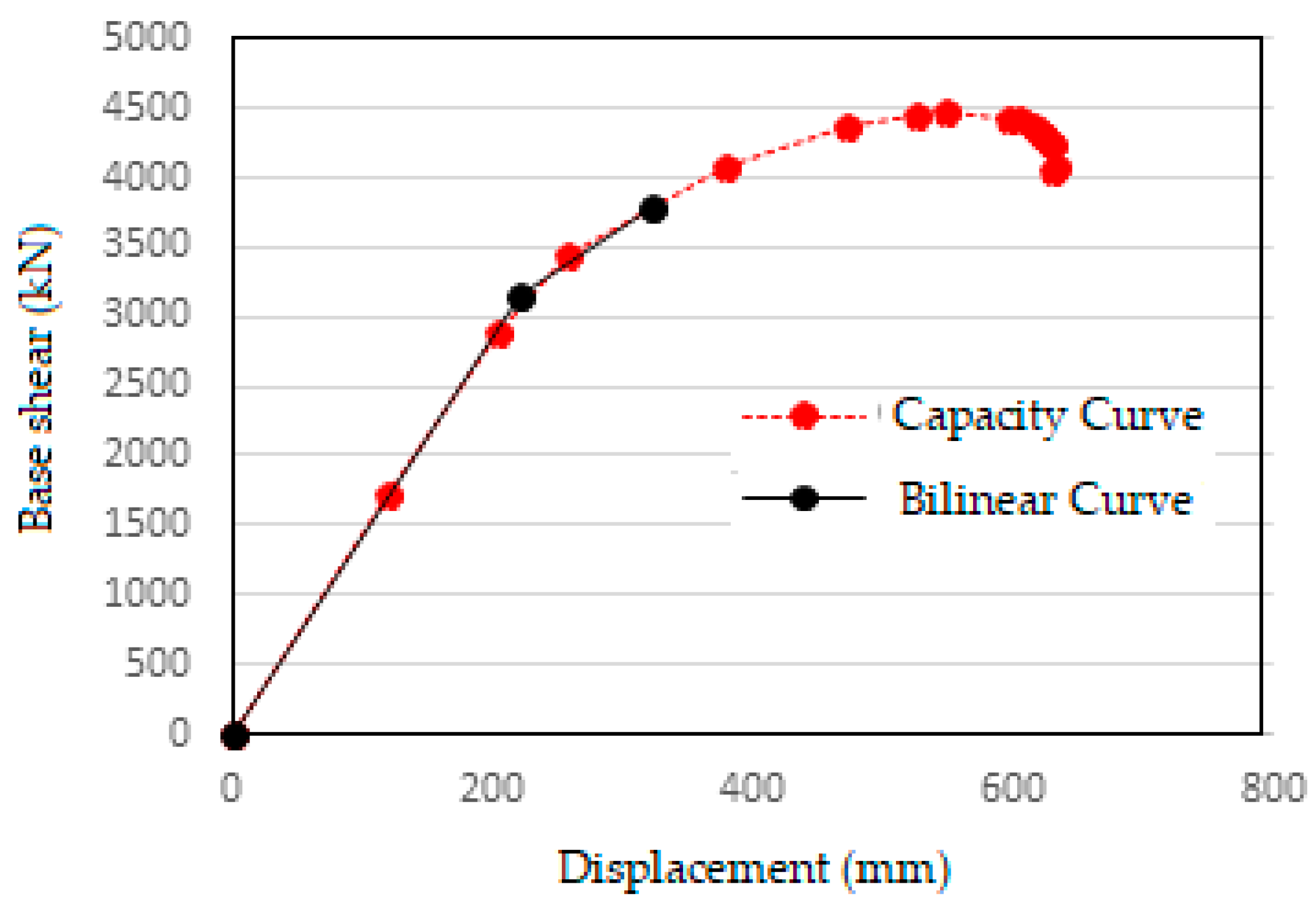
Figure 11. The target displacement calculated according to ASCE 41-13 is shown in
Figure 12.
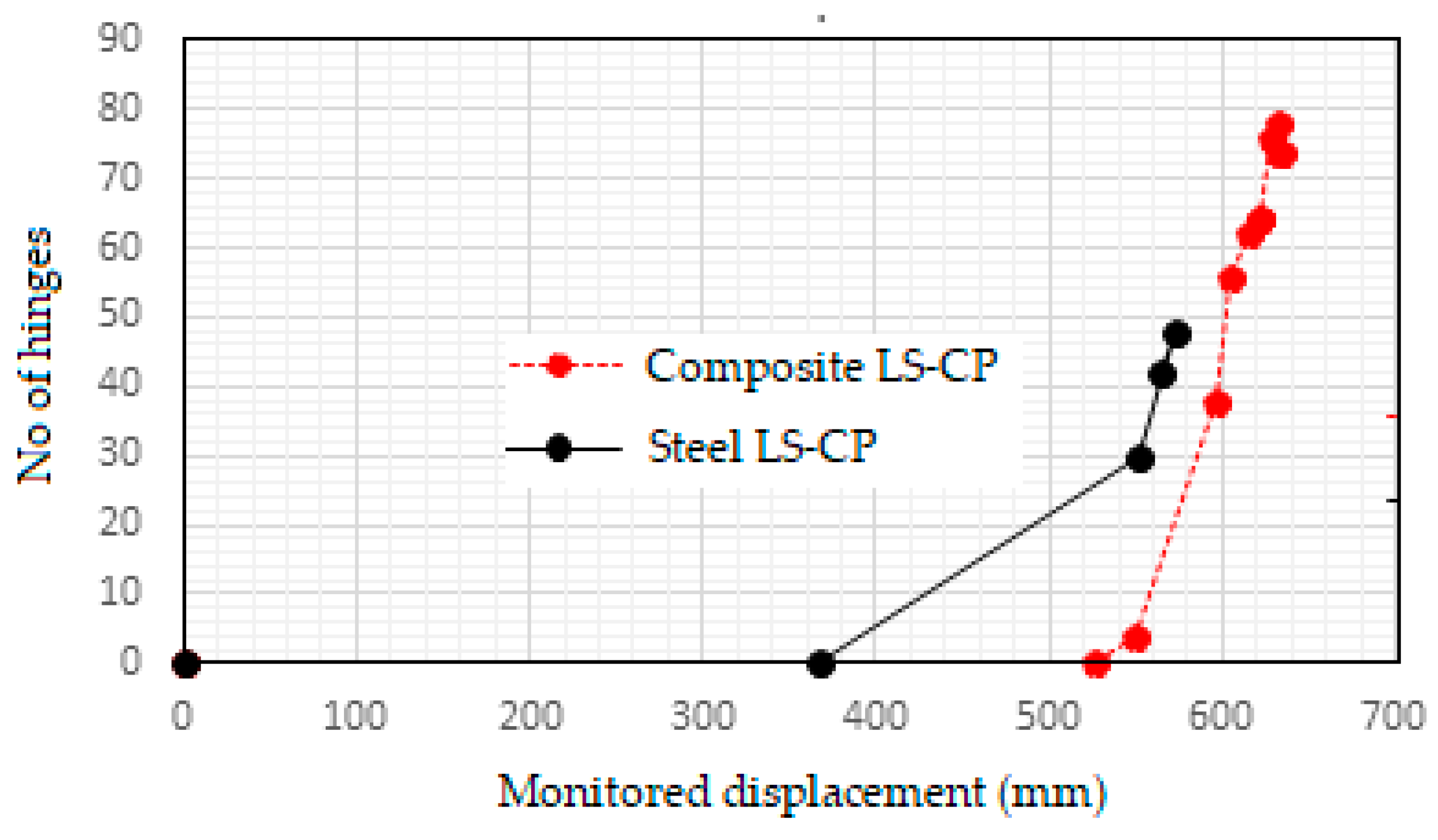
No. of hinges crossing the CP threshold
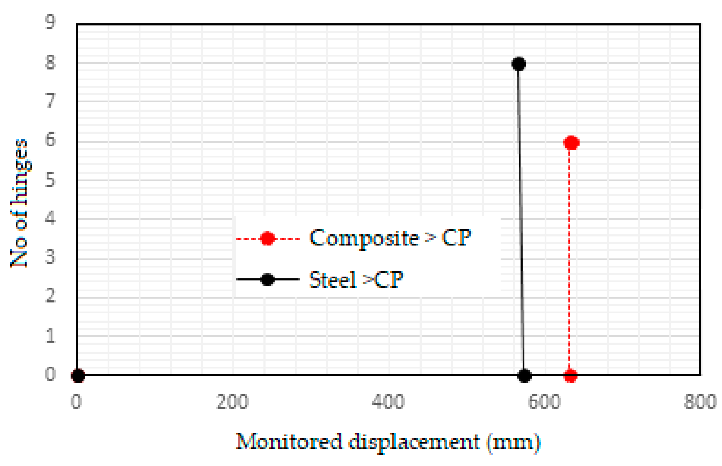
It is clearly visible in the graph that the number of hinges over CP level is greater for the steel frame when it fails. At the same displacement load, no hinges over CP level are formed in composite frame. The composite frame starts developing hinges over CP level only at a greater monitored displacement when it fails.
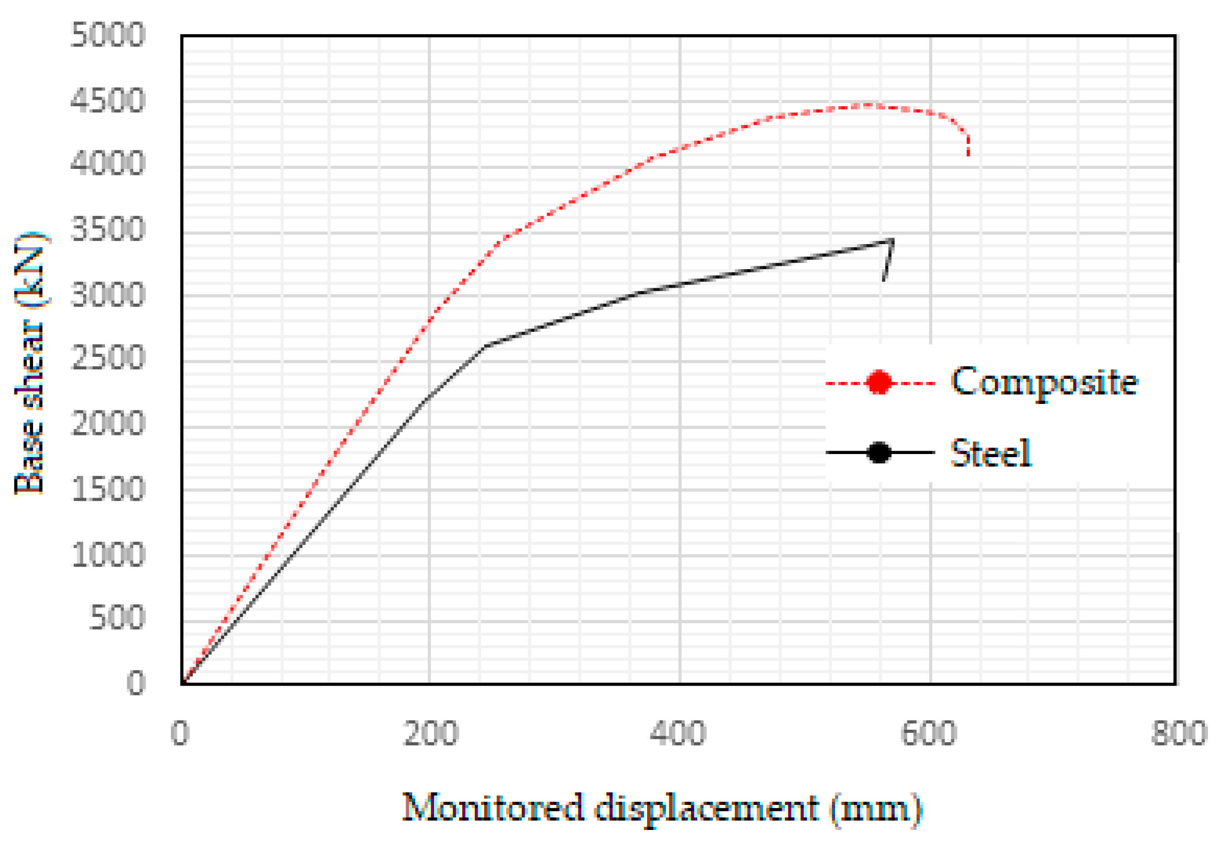
Structural characteristics of steel and composite frame are evaluated. The static pushover curve of steel and composite frame is shown in
Figure 15. It shows the lateral resistance vs. deformation of the structures until they reach failure from a global standpoint.
Further
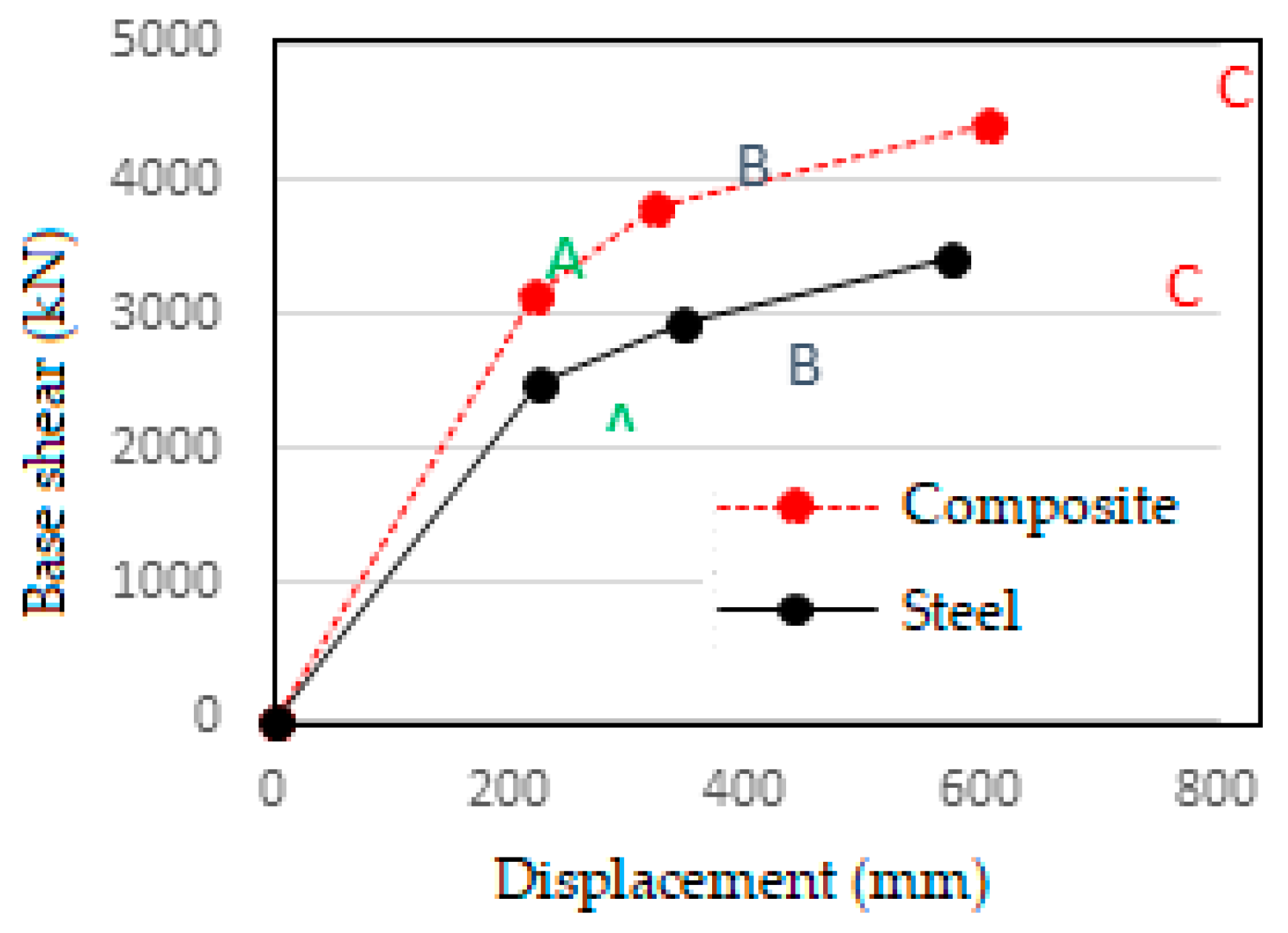
Figure 16 shows the capacity curve idealized according to ASCE 41-13 NSP. The seismic characteristics of both frames can be calculated from these curves. The details of idealized graph are given in
Table 9.
From the idealized curve the overall properties of the frames are calculated as follows:
i) Global stiffness of the frames:
The stiffness of the frames in various phases is found by taking the slope of the ideal curve.
a) Composite frame:
Stiffness in the region OA = 3140.79/220.009 = 14.28 kN/mm = 14275.7 kN/m
(Elastic region)
Stiffness in the region AB = (3787.86-3140.79)/(322.69-220.009) = 6.3 kN/mm = 6301.8 kN/m (Inelastic region)
Stiffness in the region BC = (4414.63-3787.86)/(605.24-322.69) = 2.22kN/mm = 2218.2 kN/m (Inelastic region)
b) Steel frame:
Stiffness in the region OA = 2508.35/223.709 = 11.21 kN/mm = 11212.6 kN/m
(Elastic region)
Stiffness in the region AB = (2954.46-2508.35)/(344.01-223.71) = 3.71 kN/mm = 3708.5 kN/m (Inelastic region)
Stiffness in the region BC = (3432.52-2954.46)/(572.01-344.01) = 2.09 kN/mm = 2096.7 kN/m (Inelastic region)
ii) Ductility:
Ductility can be measured as the ratio of maximum deformation to the Idealized yield deformation.
a) Composite frame:
μ = 605.24/220.009 = 2.75
b) Steel frame:
μ = 572.011/223.709 = 2.56
iii) Lateral strength:
It is the maximum resistance that the structure offers during the entire history of resistance vs deformation.
a) Composite frame:
Maximum strength, Vb max = 4414.6 kN
b) Steel frame:
Maximum strength, Vb max = 3432.5 kN
From the calculations the overall lateral stiffness, ductility and strength of composite frame is found to be greater than that of steel frame.
From the graph in
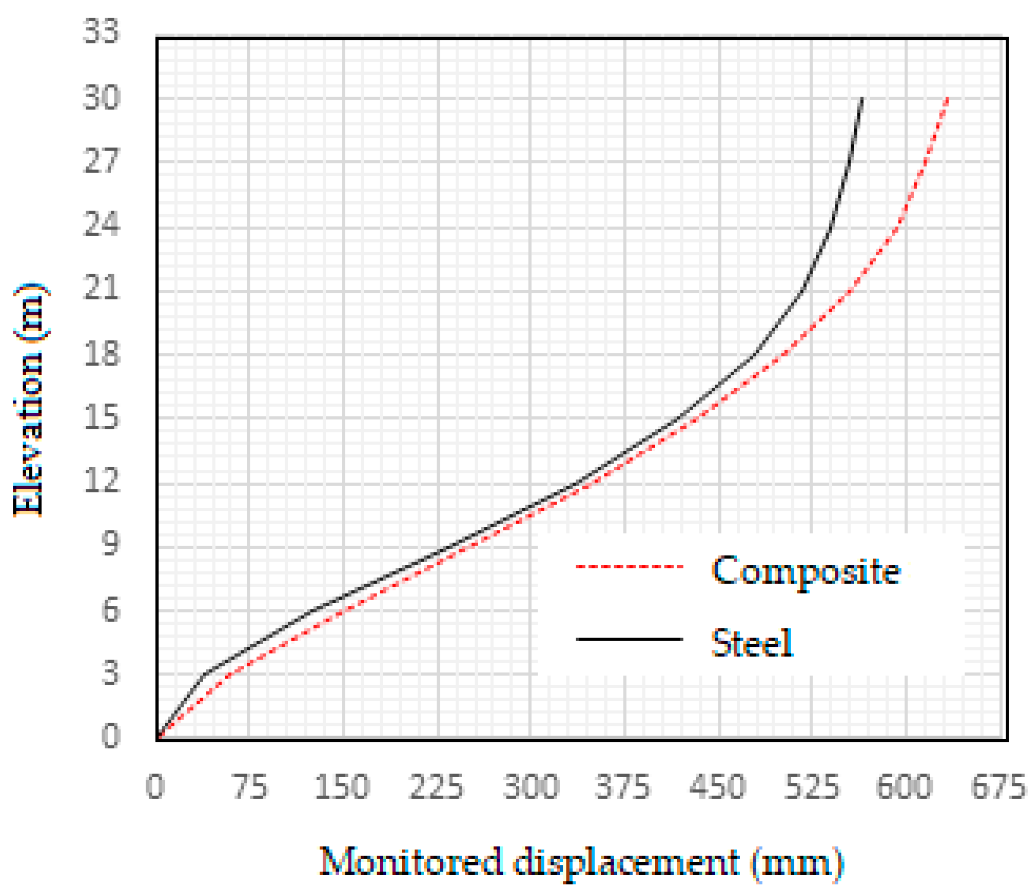
Figure 17 maximum monitored top story displacement at the time of collapse of composite frame and steel frame are 633.79 mm and 563.90 mm respectively.
From the graph in
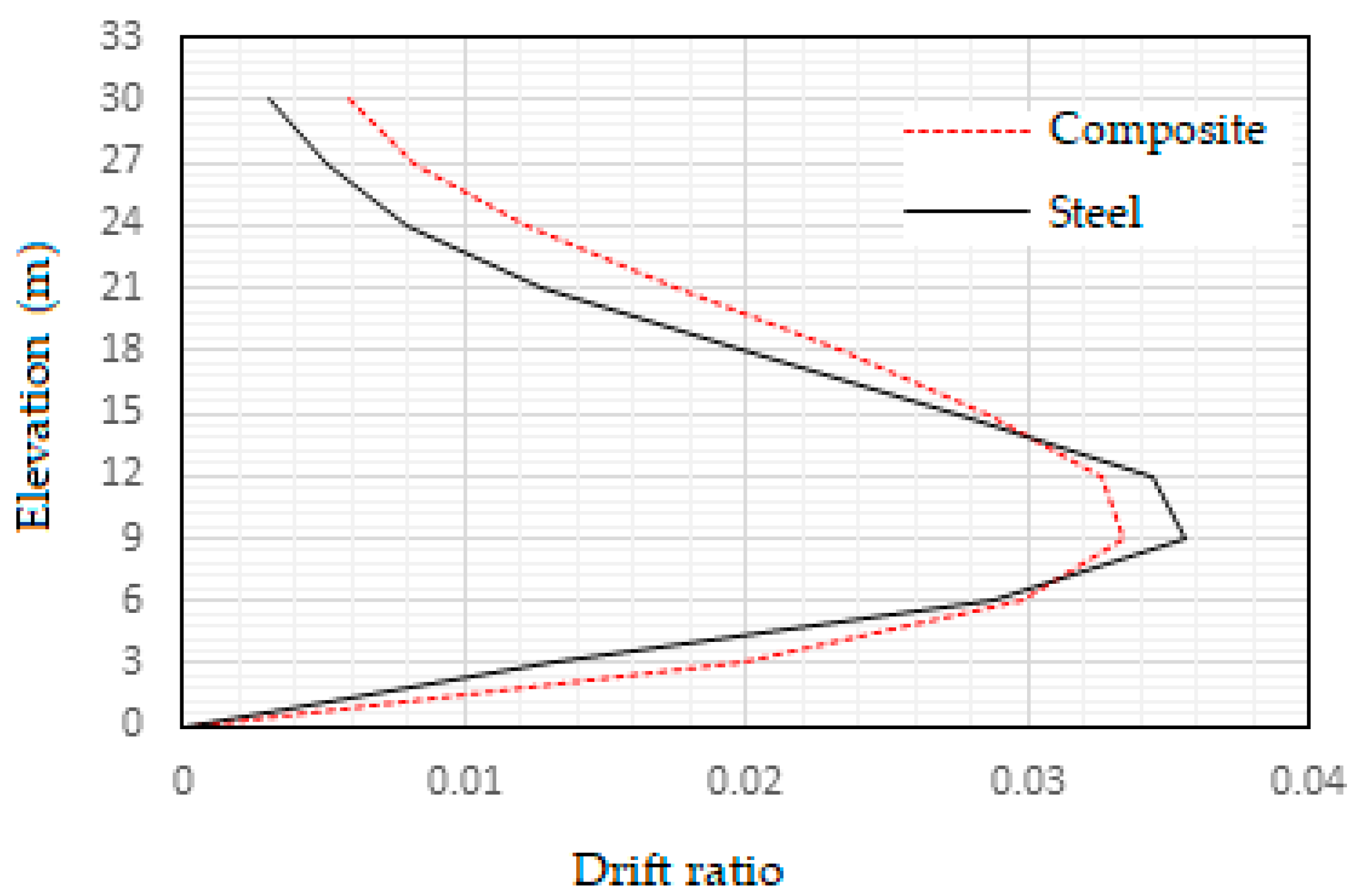
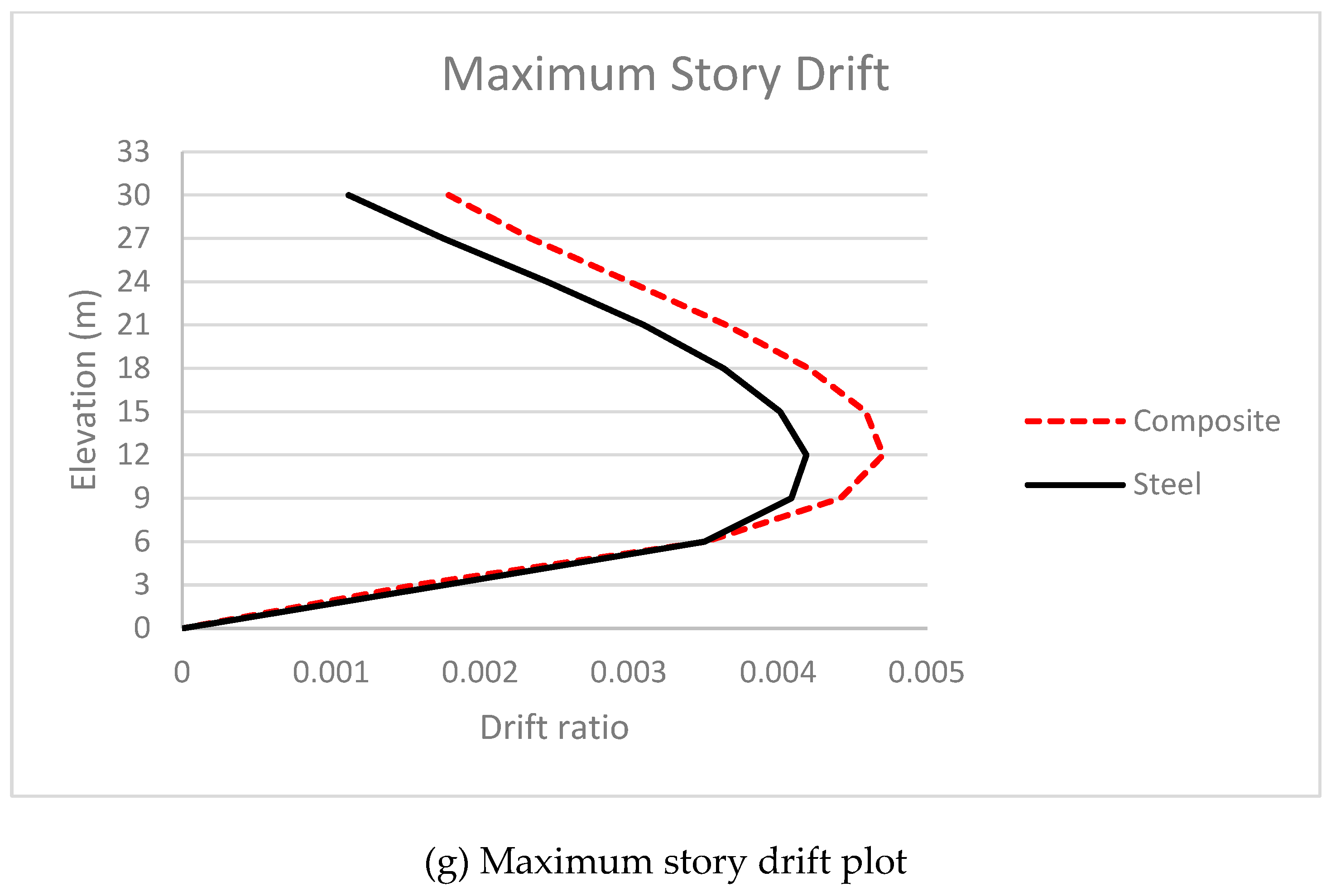
Figure 18 it is observed that maximum story drifts are experienced at third and fourth floors respectively. As a consequence of this greater number of severe hinges are found to be formed between third and fourth floors in both the steel and composite frames. The maximum drifts experienced by steel and composite frames are 0.036 and 0.033 respectively.
Moment rotation curves
i) B14H18 & C9H17 comparison:
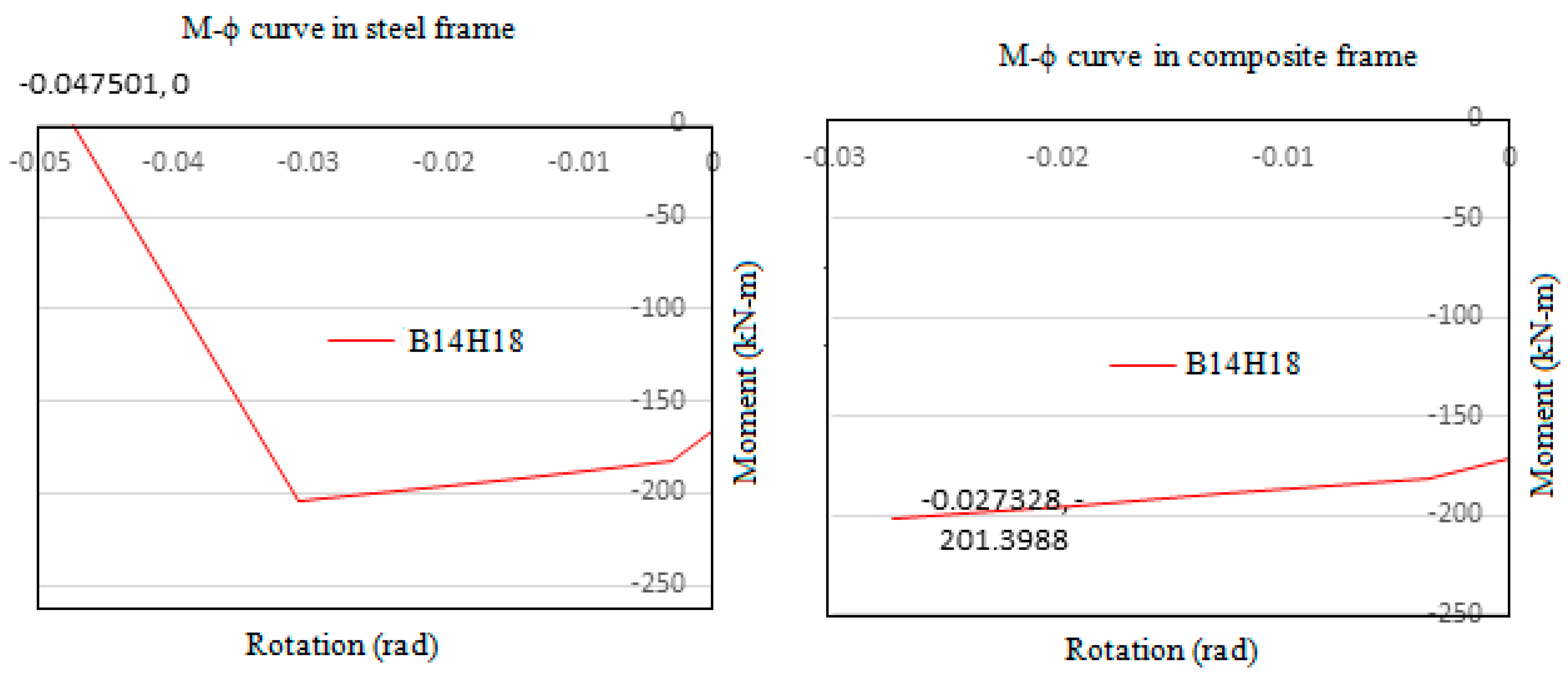
Since story drift is maximum in the third-floor level, more severe hinges were formed here. Hence from third floor, for a monitored displacement of 563.9mm moment values of two adjacent hinges from Beam number 14 and Column number 9 is compared here. Where, Column 9 comes directly below Beam number 14. Just before failure, the hinge in steel beam was subjected to a moment of 205.51kNm and underwent a rotation of 0.032rad whereas the hinge in composite beam reached a lesser moment of 201.33kNm and rotation of 0.027 rad which prevented it from completely failing. It is observed that the moment taken up by C9H17 hinge in composite frame is 547.5kNm and that of steel frame is 463.4kNm. This indicates that the column in composite frame attracted more load towards it owing to its greater stiffness and prevented the failure of beam. Similar trend is observed throughout the composite frame which in effect reduced the number of hinges in composite frame compared to steel frame. The hinge details are shown in
Table 10,
Table 11 and
Table 12. And the moment-rotation curves are shown in
Figure 20. The selected hinges are shown below.
Figure 19.
formation of hinges for composite and steel frames.
Figure 19.
formation of hinges for composite and steel frames.
The column hinges at base story are compared here. The maximum moment taken by columns in composite frame before failure of the structure is greater than that of steel frame columns before its failure indicating its greater stiffness.
Time History Analysis
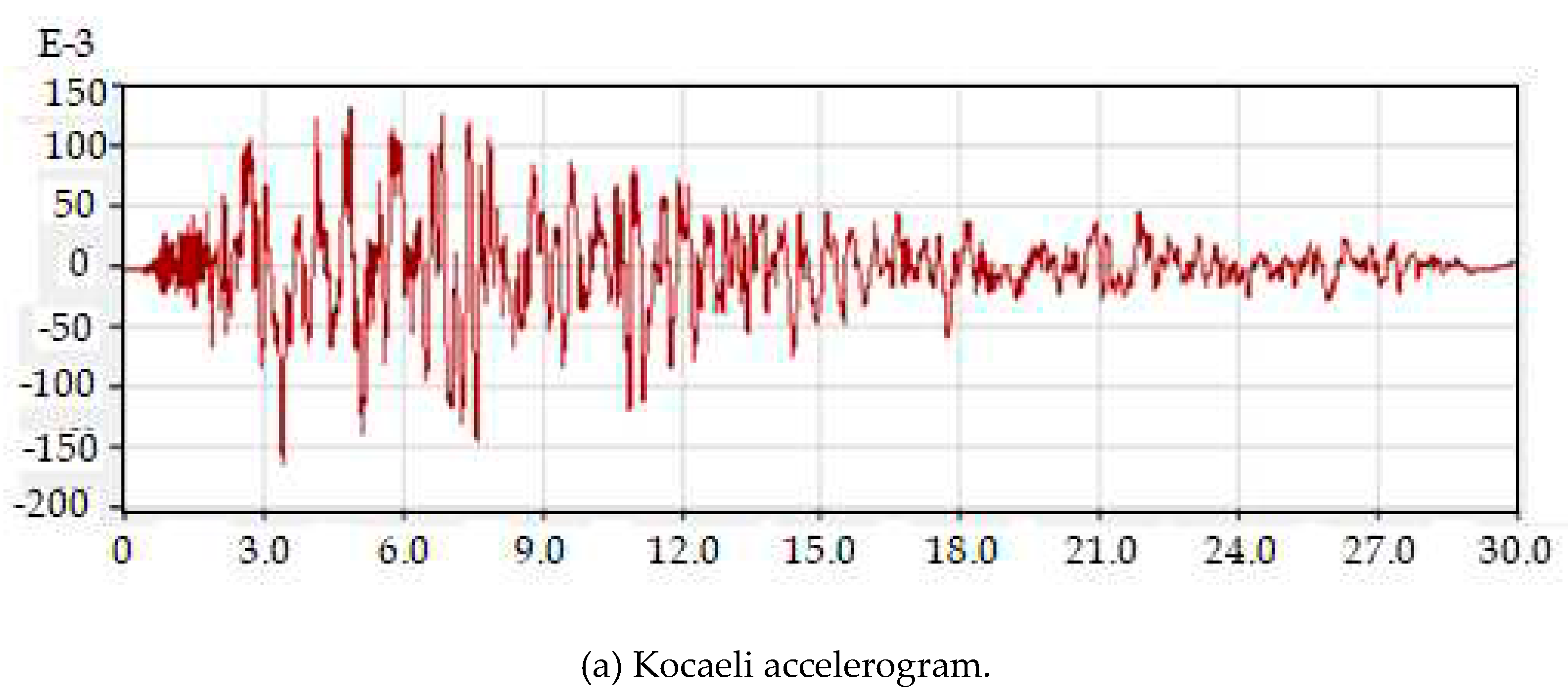
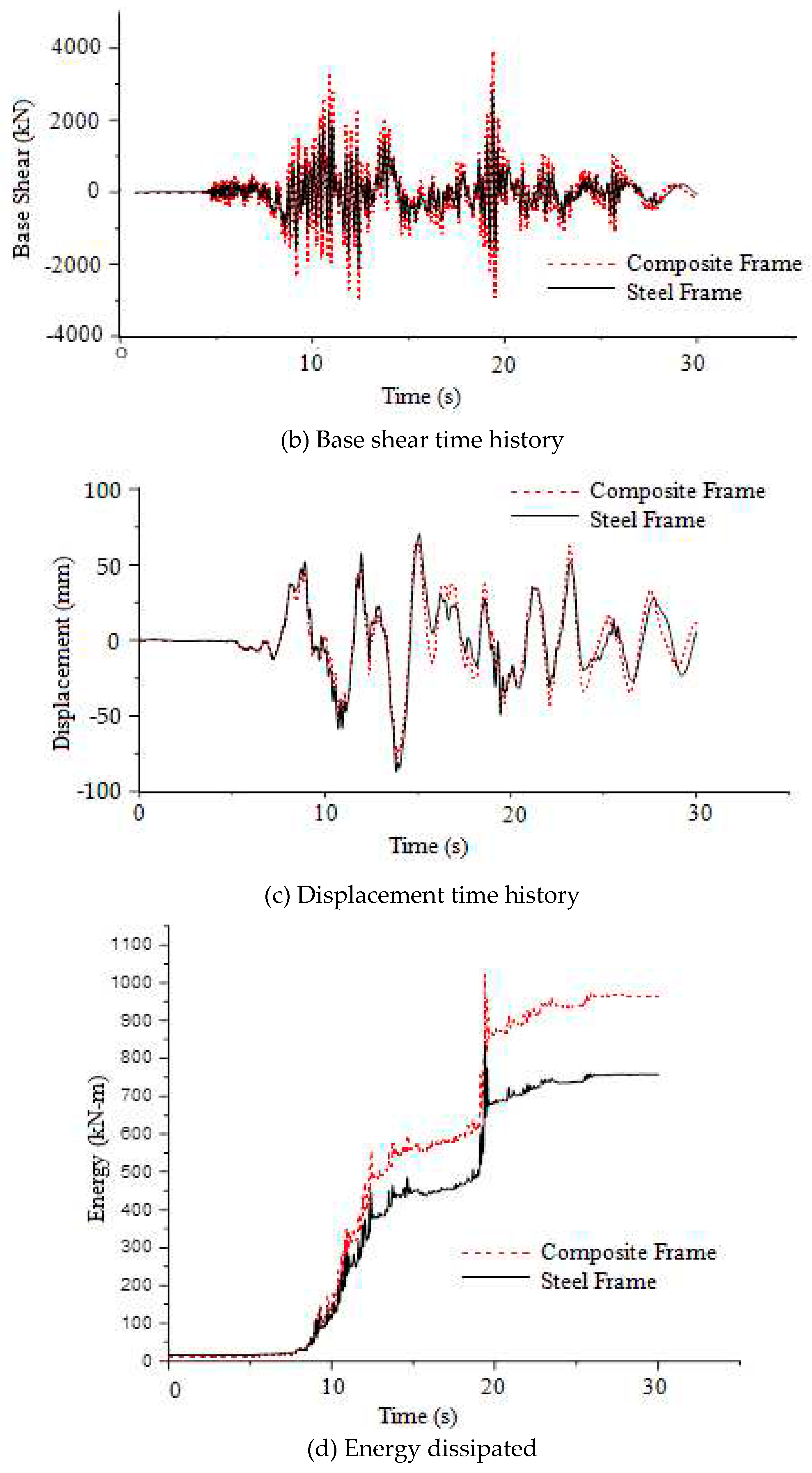
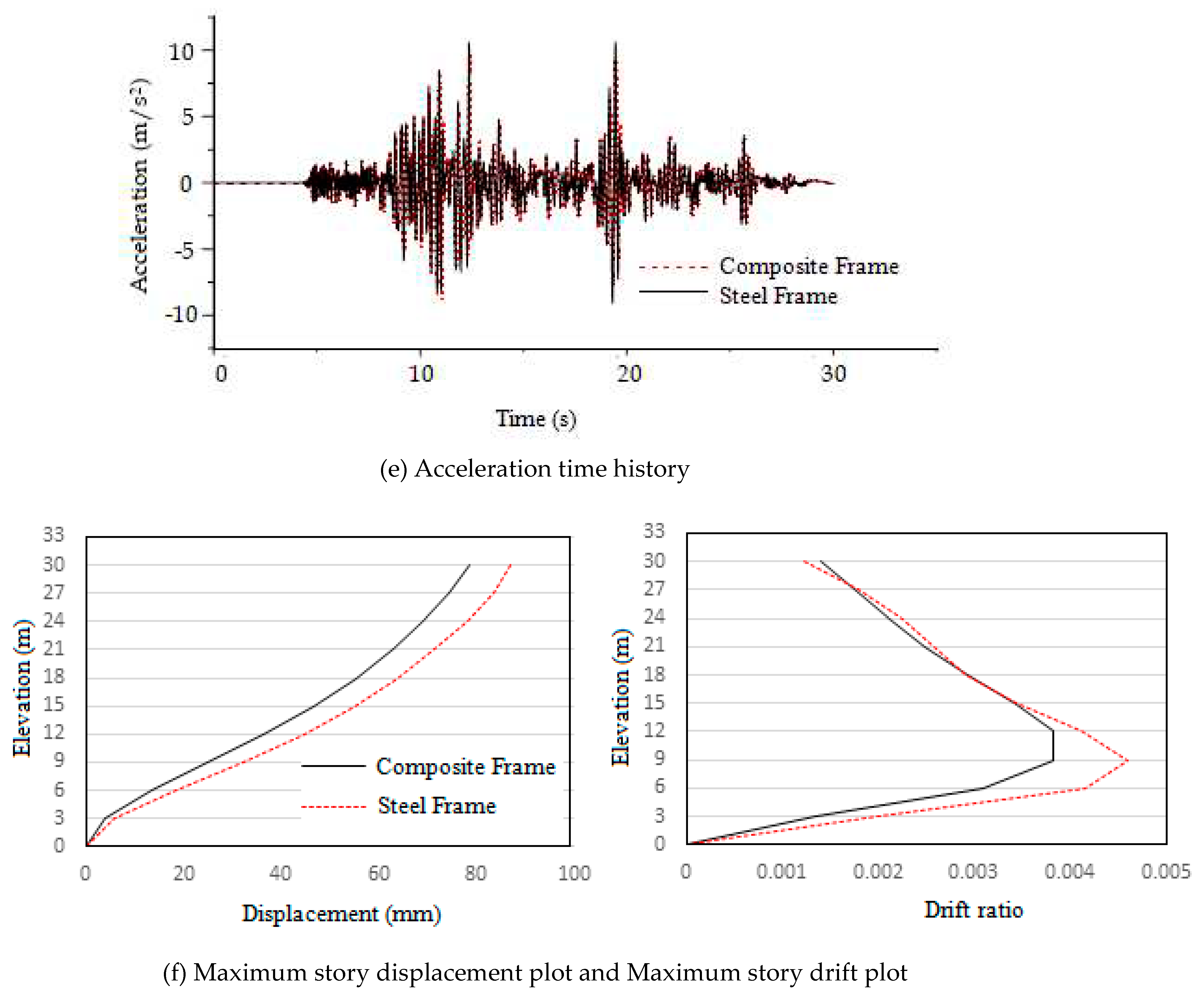
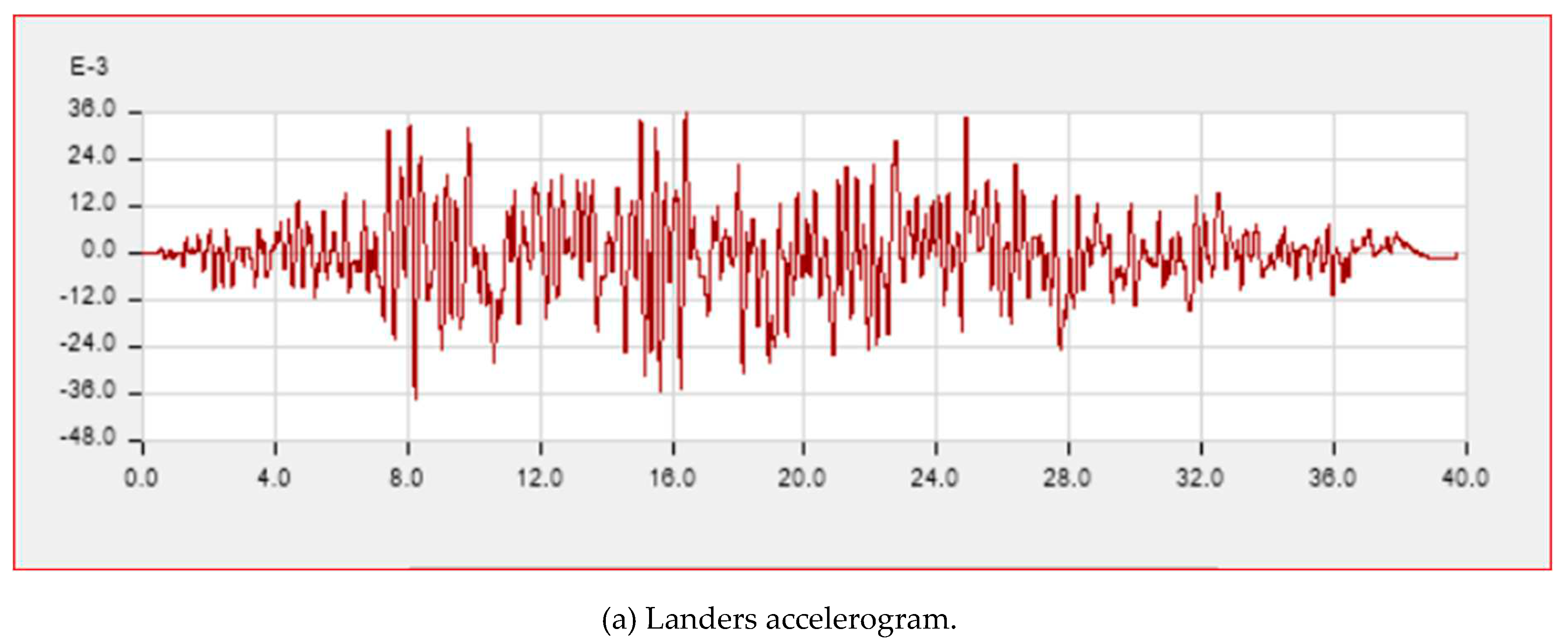
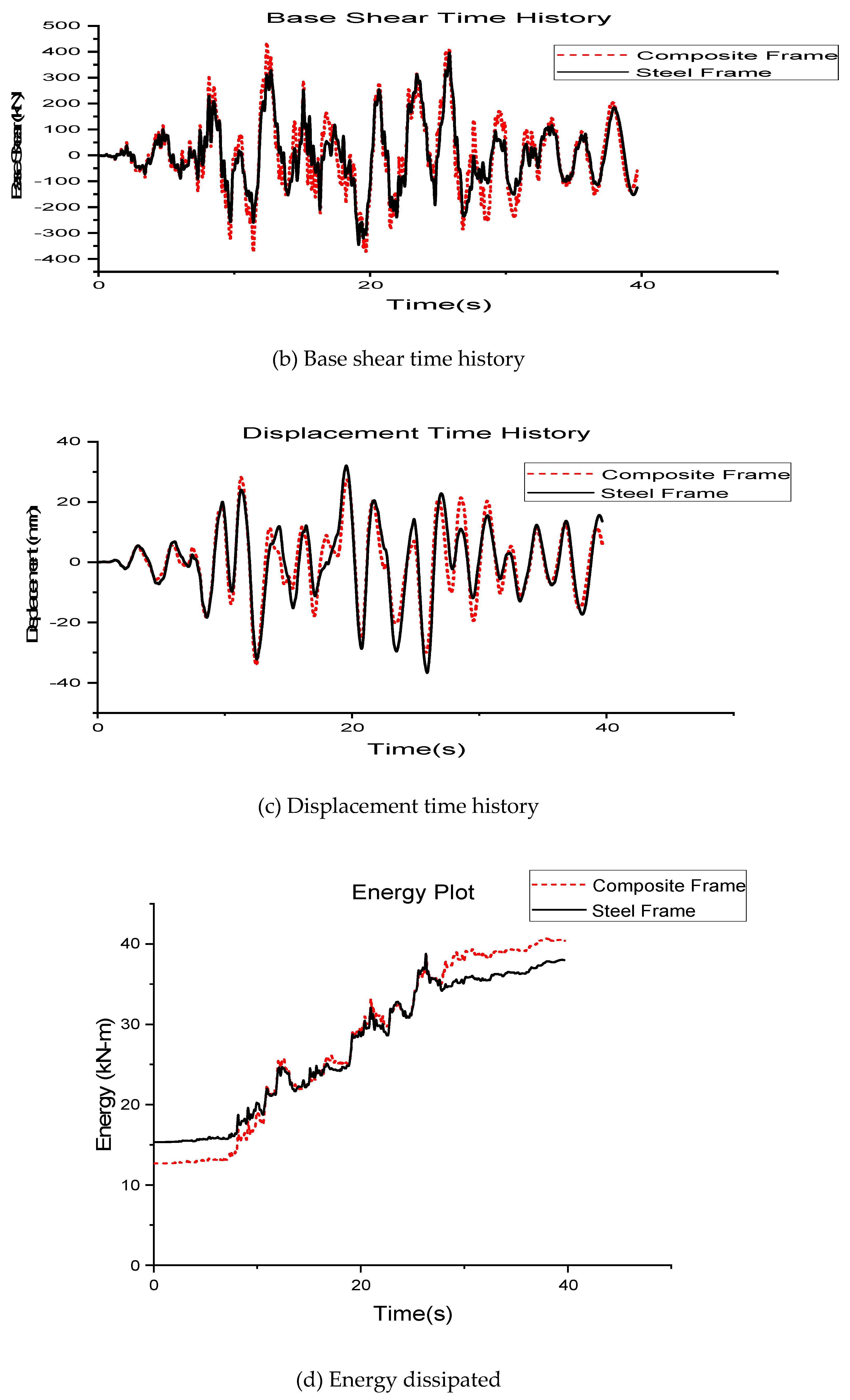
Nonlinear direct integration time history analysis has been performed along the horizontal x-direction on both steel and composite frames respectively. The time histories for dynamic analysis in this study was taken from Pacific Earthquake Engineering Research (PEER) ground motion database. Two near field and two far field ground motions were selected for the comparative study. PEER database has the option to filter and do ground motion scaling online. The design spectrum of IS1893:2002 for Site II, Seismic zone V and damping of 5% is used as the target spectrum. For selection of ground motions epicentral distances of 0-15km and 50-150km were given for near field and far field earthquakes respectively. In order to keep the scale factor from getting too high or too low the range of scale factor was given as 0.5 - 2.0, so that the selected ground motions are not having huge variations from the IS target spectrum. The period points were given as 0.47, 1, 3.7 (0.2T – 1.5T).
Earthquake details
The earthquakes which occur in fields near to the fault are called near field earthquakes. There is still disagreement among researchers on which range should an earthquake be considered as near field. Many suggest a range of up to 10-60 kilometers around the fault as near field range. According to UBC-97 code a distance less than 15km from the epicenter is in the near field range. The details of time histories are given in
Table 13. [
16].
The analysis results are shown in the sections below.
For Kocaeli (Near field) Horizontal component 180°, Duration = 30s, DT = 0.005s, f = 0.125Hz
For Duzce (Near field), Horizontal component 180°, Duration = 30.004, DT = 0.004s, f = 0.0375Hz
For Landers (Far field), Horizontal component 0°, Duration = 39.655s, DT = 0.005s, f = 0.08Hz
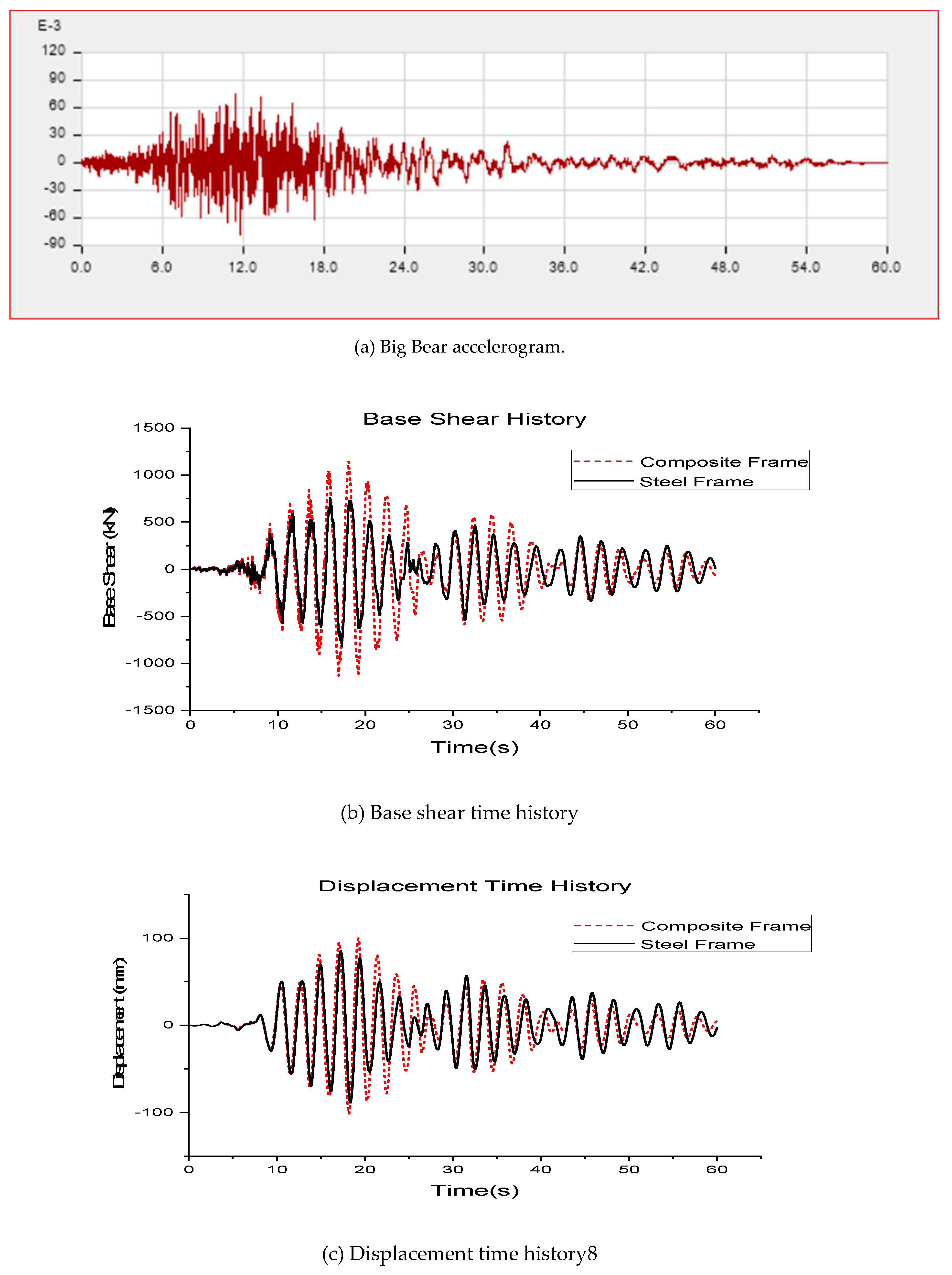
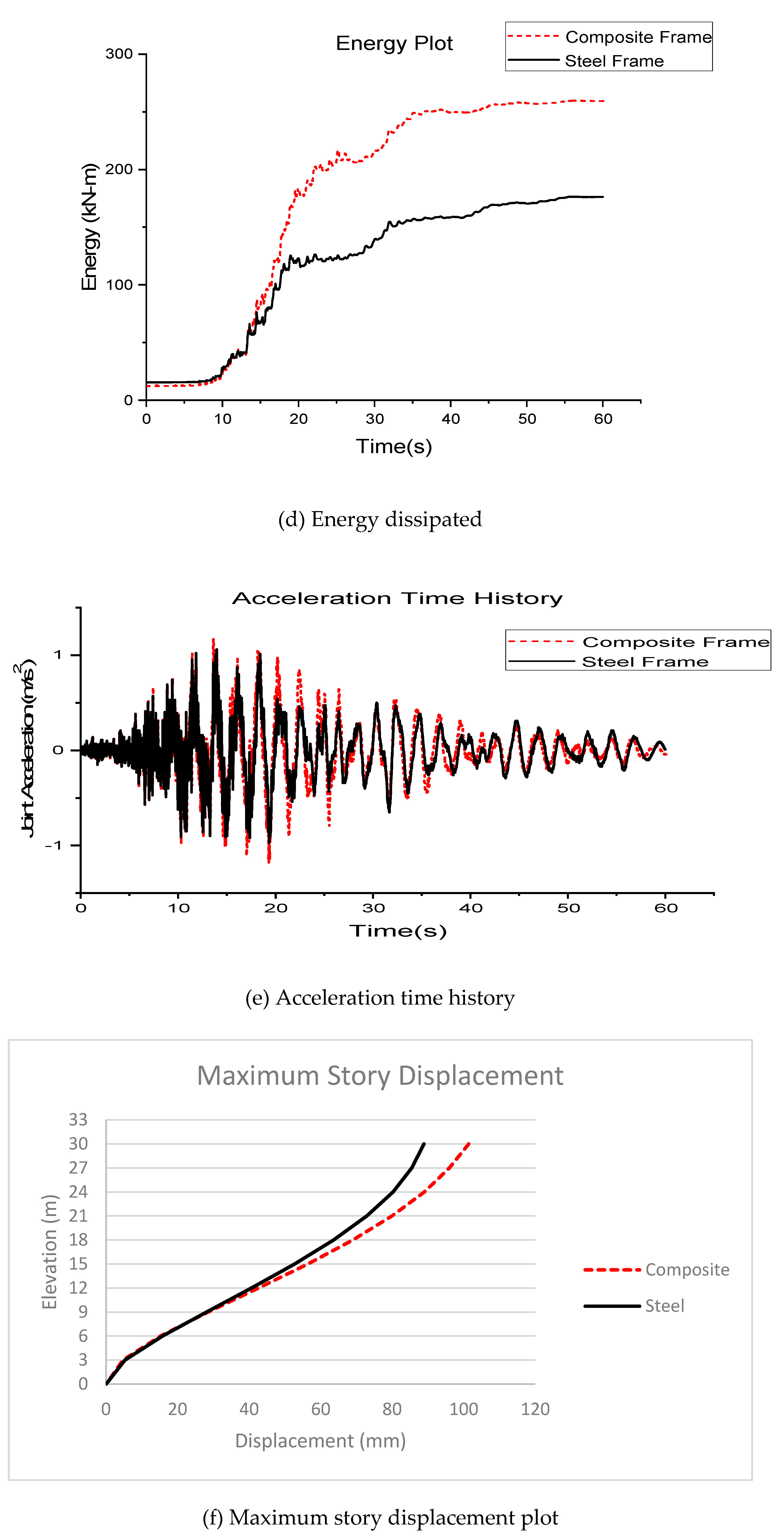
For Bear (Far field), Horizontal component 090°, Duration = 60s, DT = 0.02s, f = 0.24Hz
Comparison of earthquake responses
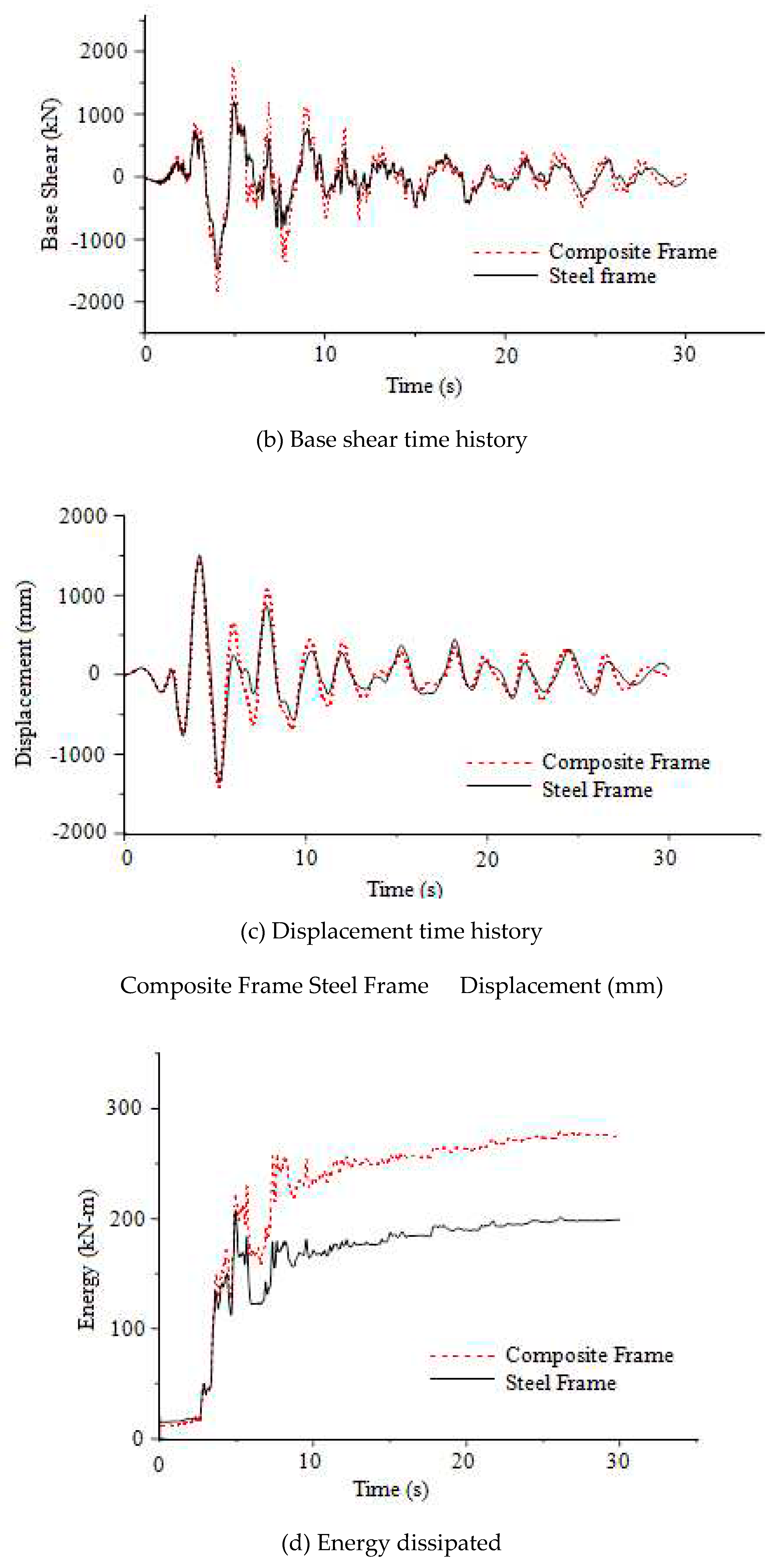
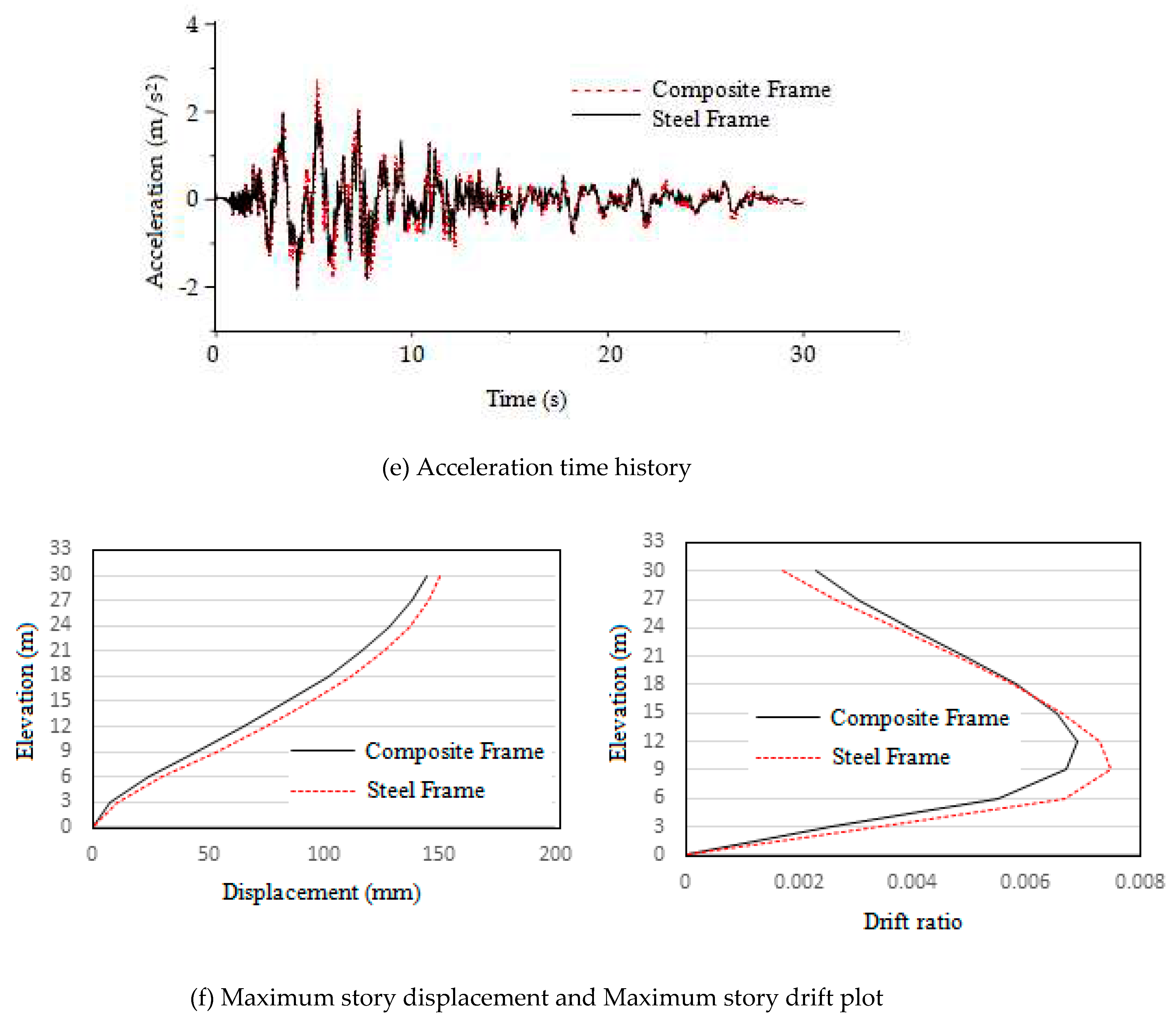
From the graphs obtained from nonlinear direct integration time history analysis the maximum responses of both the composite and steel frames are compiled to
Table 14.
From
Table 14 it is clear that the displacement and story drifts are greater for steel frame compared to composite frame. However, the displacement and drift values are found to be more dependent on the frequency of the earthquakes and how much closer it is to the natural frequency of the frames. It is evident from the table that even though Duzce is a near field earthquake its displacement and drift values on frames are lesser than that of far field earthquake Big Bear. The reason for this is that the frequency of Big Bear 0.24Hz is closer to the natural frequencies of steel and composite frame 0.40Hz and 0.44Hz respectively, whereas frequency of Duzce is 0.0375Hz which is not close to the natural frequency of both frames. The frequency of Kocaeli is 0.13Hz which again is closer to the natural frequency of frames and hence has greater displacement and drift values as well. The frequency of Landers 0.08Hz is not close to natural frequencies of the frames and hence has lesser responses. The above said differences in values of displacement and drifts are due to the effect of resonance.
The other three responses like base shear, joint acceleration and energy dissipated are greater for the composite frame compared to steel frame probably owing to its greater mass and stiffness. From
Table 14 it is also evident that the base shear, joint acceleration and energy dissipated are greater for the near field earthquakes compared to the far field earthquakes probably because of the close proximity of frames to the earthquake epicenter. The near field earthquakes have therefore released more energy to both the frames than far field earthquakes.
It can be inferred from the results that the overall response and damage on the frames due to the earthquake depends on two main factors specifically the frequency of the earthquake and the proximity of the epicenter to the site where buildings are located. A combination of these two factors defines the extent of damage the building undergoes due to the earthquake.
Comparison of column hinge C6H1 at base story
The column hinge C6H1 at base story is compared here. The maximum moment and rotation underwent by this column in composite and steel frame is shown in the
Table 15.
It is observed that column hinges in both the frames have remained within the immediate occupancy level safety throughout the ground excitation periods of all selected earthquakes. But the composite column has underwent slight rotation and taken more moment compared to steel frame. Similar to what was observed in the pushover analysis same trend is being observed here. This additional stiffness of the composite frame has significantly reduced the number of severe hinges formed and thus has a role in prolonging its ability to withstand critical collapse damages. Moreover, the values indicate that both the frames have experienced greater moments and rotations in case of near filed earthquakes than far field earthquakes.
Quantity of Materials Comparison
Composite frame requires 21 percent less structural steel compared to steel frame. But it needs 85 percent more concrete and an additional 6 percent Fe 415 reinforcement bars with respect to the structural steel required in steel frame. The quantities of materials for steel and composite frames are shown in Figure 28 (a), (b) and
Table 16.
Figure 25.
(a) Quantity of structural steel and concrete (b) Quantity of metal deck, shear studs and Fe415.
Figure 25.
(a) Quantity of structural steel and concrete (b) Quantity of metal deck, shear studs and Fe415.
5. Conclusions
The conclusion drawn from the present study are
The results from response spectrum analysis show that the displacements and drifts are greater in steel frames and responses such as story shears, overturning moments and story stiffness are greater in composite frames.
Responses in both x and y directions are similar for both frames due to the symmetric configuration.
Pushover analysis results show that the composite frame performed better in the inelastic region. From the idealized capacity curve, the stiffness of the composite frame is 21.5% more in the elastic region and 41.2% more in the nonlinear region initially and 5.5% more when nearing collapse than that of the steel frame.
The ductility ratio of the composite frame is 2.75 and that of the steel frame is 2.56.
The lateral strength of the composite frame from the idealized capacity curve is 4414.6kN and that of the steel frame is 3432.5kN.
The maximum base shear value in the composite frame is 22.3% more than that of the steel frame.
A larger number of severe hinges were formed on the third and fourth floors in both frames because of the greater inter-story drifts on these floors.
The steel frame has 8.4% more story drift than the composite frame.
The hinge results show that the columns in the composite frame attracted more lateral load compared to the steel frame. Due to this, a smaller number of hinges went beyond the collapse prevention threshold in the composite frame compared to the steel frame. The composite frame redistributed the lateral loads better than the steel frame, prolonging its failure.
The performance points using the capacity spectrum method for steel and composite frames as per IS1893:2002 are (2875.25kN, 320.74mm) and (3733.57, 312.26mm) respectively for the design-based earthquake (DBE).
The target displacement points using the displacement coefficient method for steel and composite frames as per IS1893:2002 are (2954.46kN, 344.01mm) and (3787.86kN, 322.69mm) respectively for a design-based earthquake (DBE).
From time history analysis, it is concluded that the displacement and drift values are found to be more dependent on the frequency of the earthquakes and how close they are to the natural frequency of the frames, due to the effect of resonance. The more the frequencies are closer, the greater the response.
The base shear, joint acceleration and energy dissipated in the frames depend on the proximity of the earthquake epicenter to the frame, i.e., for near field ground excitations these values are greater and for far field ground excitations vice versa.
The extent of damage to the structure due to the earthquake depends on both the frequency of the earthquake and the proximity of the epicenter to the building.
In both pushover analysis and time history analysis, the hinges were formed of beam elements rather than column elements in the case of both steel and composite frames, as they were designed for strong column - weak beam criteria.
The composite frame requires 21% less structural steel compared to the steel frame and 85% more concrete compared to the steel frame. In addition, the composite frame requires 6% more steel for the Fe415 rebars.
It can be inferred from the current research that the overall inelastic performance of composite frame is superior to steel frame for the same plastic moment capacity of sections.
Author Contributions
Conceptualization, validation, analysis, resources, data creation, writing original draft and preparation are done by Pram Gajbhiye. Methodology, writing, review and editing is performed by Dr. Rajan Wankhede. All authors have read and agreed to the published version of the manuscript.
Funding
This research received no external funding.
Data Availability Statement
Data may be available on request.
Conflicts of Interest
The authors declare no conflict of interest.
References
- Whittaker, A., Constantnou, M., Tsopelas, P.: Displacement Estimates for Performance Based Seismic Design. Journal of Struct. Division., ASCE, Vol 124 (8), pp. 905-912, (1998). [CrossRef]
- Ghobarah, A., Abou-Elfath, H., & Biddah, A. (1999). Response-Based Damage Assessment of Structures. Earthquake Engineering and Engineering Seismology, 28(4), 79–104. [CrossRef]
- Chopra, A. K., Chintanapakdee, C.: Comparing response of SDF Systems to Near-Fault and Far-Fault Earthquake Motions in the Context of Spectral Regions. Earthquake Engineering and Structural Dynamics, Vol. 30, pp. 1769- 1789, (2001). [CrossRef]
- Xue, Q.: A Direct Displacement Based Seismic Design Procedure of Inelastic Structures. Engineering Structures, Vol. 23 (11), pp. 1453-1460, (2001). [CrossRef]
- Elenas, a, & Meskouris, K. (2001). Correlation study between seismic acceleration parameters and damage indices of structures. Engineering Structures, 23(6), 698–704. [CrossRef]
- IS 1893: 2002 Indian code for earthquake resistant structures.
- IS 12778: 2004 Indian standard code of practice for hot rolled parallel flange steel sections for beams, columns and bearing piles – Dimensions and section properties.
- IS 800: 2007 Indian standard code of practice for general construction in steel.
- Mohd Y.A.Y., David A.N., (2007), “Cross-sectional properties of complex composite beams”, Engineering structures 29, 195-212, 2007. [CrossRef]
- Gewei, Z., & Basu, B. (2010). A study on friction-tuned mass damper: harmonic solution and statistical linearization. Journal of Vibration and Control, 17(5), 721–731. [CrossRef]
- Sayani, P. J., Erduran, E., Ryan, K. L.: Comparative response assessment of minimally compliant low-rise base isolated and conventional steel moment resisting frame buildings, Journal of Structural Engineering. ASCE, Vol. 137 (10), pp. 1118-1131, (2011). [CrossRef]
- Gray, B. M., Christopoulos, C., Ph, D., Eng, P., Packer, J., & Gray, M. (2012). A New Brace Option for Ductile Braced Frames. Modern Steel Construction, 40–43.
- Rajan L. Wankhade, Amarsinh B. Landage, (2014). Static Analysis For Fixed Base And Base Isolated Building Frame., Proceedings of National Conference on Advances in Civil and Structural Engineering (NCACSE-2014).
- Rajan L Wankhade, (2014). Performance Based Design and Estimation of Forces for Building Frames with Earthquake Loading., International Conference on Recent Trends and Challenges in Civil Engineering December 12-14, 2014, MNNIT Allahabad, India.
- Rajan L. Wankhade, Amarsinh B. Landage, (2016). Performance Based Analysis and Design of Building Frames with Earthquake Loading. International Journal of Engineering Research., 5(1), 106-110.
- Rajan. L. Wankhade, (2017). Performance Analysis Of Rc Moment Resisting Frames Using Different Rubber Bearing Base Isolation Techniques., International Conference on Innovations in Concrete for Infrastructure Challenges Nagpur, India October 6-7.
- Titikesh A., Bhatt G., (2017), “Optimum positioning of shear walls for minimizing the effects of lateral forces in multistorey buildings”, Archives of civil engineering, Vol. LXIII, Issue 1, 2017.
- Bazarchi E., Hosseinzadeh Y., Panjebashi A.P., (2018), “Investigating the in-plane flexibility of steel-deck composite floors in steel structures”, International journal of structural integrity, Vol.9, No.5, 705-720, May 2018. [CrossRef]
- Boukhalkhal S.H. and Jhaddoudene A.N.T., Neves L.F.D.C., de Silva V.P.C.G., Madi W., (2019), “Performance assessment of steel structures with semi-rigid joints in seismic areas”, International journal of structural integrity, Vol.11, No.1, 13-28, May 2019.
- Chittaranjan B. Nayak, Umesh T. Jagadale, Keshav M. Jadhav, Samadhan G. Morkhade, Gunavant K. Kate, Sunil B. Thakare & Rajan L. Wankhade , (2021). Experimental, analytical and numerical performance of RC beams with V-shaped reinforcement. Innov. Infrastruct. Solut., 6, (2). [CrossRef]
- Wankhade, R.L., Sawarkar, A., Chandwani, A., Chavan, S., Malkar, P., Sawarkar, G. (2022). Seismic Fragility of Buildings Subjected to Pounding Effects with Soil–Structure Interaction. In: Gupta, A.K., Shukla, S.K., Azamathulla, H. (eds) Advances in Construction Materials and Sustainable Environment. Lecture Notes in Civil Engineering, vol 196. Springer, Singapore. [CrossRef]
Figure 1.
Plan and elevation of a building frame.
Figure 1.
Plan and elevation of a building frame.
Figure 2.
Encased Section, Steel Section and Deck slab section for composite frame.
Figure 2.
Encased Section, Steel Section and Deck slab section for composite frame.
Figure 3.
Moment-curvature curve of composite column section.
Figure 3.
Moment-curvature curve of composite column section.
Figure 4.
Validation of Lateral load distribution with comparison.
Figure 4.
Validation of Lateral load distribution with comparison.
Figure 5.
Maximum story displacement and Maximum story drift along x-axis.
Figure 5.
Maximum story displacement and Maximum story drift along x-axis.
Figure 6.
Story overturning moment (kN-m) and Story Shear (kN) along x-axis .
Figure 6.
Story overturning moment (kN-m) and Story Shear (kN) along x-axis .
Figure 7.
Story stiffness along x axis and y-axis (kN/m).
Figure 7.
Story stiffness along x axis and y-axis (kN/m).
Figure 8.
Step 3: IO level hinges, Step 5: LS level hinges, Step 7: CP level hinges.
Figure 8.
Step 3: IO level hinges, Step 5: LS level hinges, Step 7: CP level hinges.
Figure 9.
Performance point as per IS1893:2002 for steel frame.
Figure 9.
Performance point as per IS1893:2002 for steel frame.
Figure 10.
Target displacement as per IS1893:2002 for steel frame.
Figure 10.
Target displacement as per IS1893:2002 for steel frame.
Figure 11.
Performance point as per IS1893:2002 for composite frame.
Figure 11.
Performance point as per IS1893:2002 for composite frame.
Figure 12.
Target displacement as per IS1893:2002 for composite frame.
Figure 12.
Target displacement as per IS1893:2002 for composite frame.
Figure 13.
Comparison of monitored displacement.
Figure 13.
Comparison of monitored displacement.
Figure 14.
Monitored displacement after collapse.
Figure 14.
Monitored displacement after collapse.
Figure 15.
Static pushover curve of steel and composite frame.
Figure 15.
Static pushover curve of steel and composite frame.
Figure 16.
Idealized capacity curve.
Figure 16.
Idealized capacity curve.
Figure 17.
Maximum monitored displacement Elevation (m).
Figure 17.
Maximum monitored displacement Elevation (m).
Figure 18.
Maximum story drifts with respect to elevation.
Figure 18.
Maximum story drifts with respect to elevation.
Figure 20.
M-ϕ curve of B14H18 in steel frame (at d=563.9mm) and composite frame (at d=563.9mm).
Figure 20.
M-ϕ curve of B14H18 in steel frame (at d=563.9mm) and composite frame (at d=563.9mm).
Table 1.
Plastic moment capacity of sections.
Table 1.
Plastic moment capacity of sections.
| Object |
Section |
Plastic moment-capacity, Mp (kN-m) |
Column
(IS 12778:2004) |
Steel |
WPB 300X300 (237.92 kg/m) |
1406.84 |
| Composite |
WPB 360x370 (165.34 kg/m)
Embedded cross section |
1407.27 |
Primary beam for both frames
(IS 800:2007) |
ISWB 300 (48.1 kg/m) |
182.80 |
Secondary beam for both frames
(IS 800:2007) |
ISLB 225 (23.5 kg/m) |
63.68 |
Table 2.
Lateral- load distribution.
Table 2.
Lateral- load distribution.
| Story |
Elevation
(m) |
Lateral load distribution (kN) |
| Software |
Manual |
| Story10 |
30 |
112.9491 |
111.799 |
| Story9 |
27 |
98.3869 |
103.4 |
| Story8 |
24 |
77.7378 |
85.2 |
| Story7 |
21 |
59.518 |
65.01 |
| Story6 |
18 |
43.7275 |
47.77 |
| Story5 |
15 |
30.3663 |
32.99 |
| Story4 |
12 |
19.4344 |
21.17 |
| Story3 |
9 |
10.9319 |
11.82 |
| Story2 |
6 |
4.8586 |
4.925 |
| Story1 |
3 |
1.2147 |
1.329 |
| Ʃ Total |
|
459.14 |
492.51 |
Table 3.
Modal time periods.
Table 3.
Modal time periods.
| Mode |
Period(s) |
| Composite |
Steel |
| 1 |
2.189 |
2.373 |
| 2 |
2.187 |
2.339 |
| 3 |
1.775 |
2.001 |
Table 4.
Comparison of maximum responses.
Table 4.
Comparison of maximum responses.
| Response |
RSx |
RSy |
| Composite |
Steel |
Composite |
Steel |
| Maximum story displacement (mm) |
41.17 |
43.43 |
41.21 |
43.96 |
| Maximum story drift |
0.0019 |
0.00214 |
0.0019 |
0.00216 |
| Story overturning moment (kN-m) |
9550.4 |
8195.9 |
9541.2 |
8046.4 |
| Story shear (kN) |
533.39 |
444.41 |
532.98 |
437.02 |
| Story stiffness (kN/mm) |
259.8 |
142.7 |
259.6 |
140.3 |
Table 5.
Hinge details of steel frame.
Table 5.
Hinge details of steel frame.
| Step |
Monitored Displ. (mm) |
Base Force
(kN) |
A-B |
B-C |
C-D |
D-E |
>E |
A-IO |
IO-LS |
LS-CP |
>CP |
Total |
| 0 |
0 |
0 |
800 |
0 |
0 |
0 |
0 |
800 |
0 |
0 |
0 |
800 |
| 1 |
120 |
1345.5072 |
800 |
0 |
0 |
0 |
0 |
800 |
0 |
0 |
0 |
800 |
| 2 |
194.075 |
2176.0667 |
798 |
2 |
0 |
0 |
0 |
800 |
0 |
0 |
0 |
800 |
| 3 |
244.108 |
2614.2609 |
736 |
64 |
0 |
0 |
0 |
776 |
24 |
0 |
0 |
800 |
| 4 |
368.062 |
3036.3915 |
678 |
122 |
0 |
0 |
0 |
690 |
110 |
0 |
0 |
800 |
| 5 |
550.505 |
3395.5062 |
654 |
146 |
0 |
0 |
0 |
656 |
114 |
30 |
0 |
800 |
| 6 |
572.011 |
3432.5150 |
652 |
146 |
2 |
0 |
0 |
656 |
96 |
48 |
0 |
800 |
| 7 |
563.901 |
3117.8298 |
652 |
136 |
4 |
0 |
8 |
656 |
94 |
42 |
8 |
800 |
Table 6.
Hinge details of composite frame.
Table 6.
Hinge details of composite frame.
| Step |
Monitored Displ. (mm) |
Base Force
(kN) |
A-B |
B-C |
C-D |
D-E |
>E |
A-IO |
IO-LS |
LS-CP |
>CP |
Total |
| 0 |
0 |
0 |
800 |
0 |
0 |
0 |
0 |
800 |
0 |
0 |
0 |
800 |
| 1 |
120 |
1713.0875 |
800 |
0 |
0 |
0 |
0 |
800 |
0 |
0 |
0 |
800 |
| 2 |
204.016 |
2884.5333 |
796 |
4 |
0 |
0 |
0 |
800 |
0 |
0 |
0 |
800 |
| 3 |
256.971 |
3445.6811 |
716 |
84 |
0 |
0 |
0 |
768 |
32 |
0 |
0 |
800 |
| 4 |
378.584 |
4078.8834 |
650 |
150 |
0 |
0 |
0 |
680 |
120 |
0 |
0 |
800 |
| 5 |
472.306 |
4378.2101 |
618 |
182 |
0 |
0 |
0 |
646 |
154 |
0 |
0 |
800 |
| 6 |
525.33 |
4455.5615 |
616 |
184 |
0 |
0 |
0 |
636 |
164 |
0 |
0 |
800 |
| 7 |
549.436 |
4473.9862 |
616 |
184 |
0 |
0 |
0 |
624 |
172 |
4 |
0 |
800 |
| 8 |
596.002 |
4430.5584 |
614 |
174 |
0 |
0 |
12 |
616 |
146 |
38 |
0 |
800 |
| 9 |
605.241 |
4414.625 |
612 |
176 |
0 |
0 |
12 |
616 |
128 |
56 |
0 |
800 |
| 10 |
614.824 |
4376.4091 |
612 |
176 |
0 |
0 |
12 |
616 |
122 |
62 |
0 |
800 |
| 11 |
620.741 |
4327.1105 |
612 |
172 |
0 |
0 |
16 |
616 |
120 |
64 |
0 |
800 |
| 12 |
620.753 |
4327.1298 |
612 |
172 |
0 |
0 |
16 |
616 |
120 |
64 |
0 |
800 |
| 13 |
628.401 |
4259.8434 |
612 |
172 |
0 |
0 |
16 |
616 |
108 |
76 |
0 |
800 |
| 14 |
631.331 |
4243.5798 |
612 |
168 |
4 |
0 |
16 |
616 |
106 |
78 |
0 |
800 |
| 15 |
631.343 |
4061.4931 |
612 |
164 |
2 |
0 |
22 |
616 |
104 |
74 |
6 |
800 |
| 16 |
633.795 |
4078.3067 |
612 |
162 |
4 |
0 |
22 |
616 |
104 |
74 |
6 |
800 |
Table 7.
Comparison of performance points.
Table 7.
Comparison of performance points.
| Parameters |
Performance point as per FEMA 440 EL |
| Composite frame |
Steel frame |
| Shear (kN) |
3733.57 |
2875.25 |
| Displacement (mm) |
312.26 |
320.74 |
| Sa (g) |
0.1886 |
0.1568 |
| Sd (mm) |
242.25 |
257.97 |
| Teff (s) |
2.18 |
2.39 |
Table 8.
Comparison of target displacements.
Table 8.
Comparison of target displacements.
| Parameters |
Target displacement as per ASCE 41-13 NSP |
| Composite frame |
Steel Frame |
| Shear (kN) |
3787.86 |
2954.46 |
| Displacement (mm) |
322.69 |
344.01 |
Table 9.
Idealised curve data.
Table 9.
Idealised curve data.
| Region |
Ideal curve composite |
Ideal curve steel |
Displacement
(mm) |
Base shear
(kN) |
Displacement
(mm) |
Base shear
(kN) |
| Elastic region |
0 |
0 |
0 |
0 |
| 220.009 |
3140.79 |
223.709 |
2508.351 |
| Plastic region |
322.69 |
3787.862 |
344.005 |
2954.464 |
| 605.241 |
4414.625 |
572.011 |
3432.515 |
Table 10.
Moment-rotation values of beam hinge B14H18.
Table 10.
Moment-rotation values of beam hinge B14H18.
| Hinge number |
Frame |
Moment, M3
(kN-m) |
Hinge state |
Hinge
level |
Rotation
(rad) |
| B14H18 |
Composite |
201.3 |
B to <=C |
LS to <=CP |
0.027 |
| Steel |
0 |
>E |
>CP |
0.047 |
Table 11.
Moment-rotation values of column hinge C9H17.
Table 11.
Moment-rotation values of column hinge C9H17.
| Hinge number |
Frame |
Moment, M3
(kN-m) |
Hinge
state |
Hinge
level |
Rotation
(rad) |
Axial force
(kN) |
| C9H17 |
Composite |
547.5 |
A to <=B |
A to <=IO |
0.0008 |
547.5 |
| Steel |
463.4 |
A to <=B |
A to <=IO |
0 |
463.4 |
Table 12.
Moment-rotation values of column hinge C6H1.
Table 12.
Moment-rotation values of column hinge C6H1.
| Hinge number |
Frame |
Moment, M3
(kN-m) |
Hinge
state |
Hinge
level |
Rotation
(rad) |
Axial force
(kN) |
| C6H1 |
Composite |
1761.5 |
B to <=C |
LS to <=CP |
0.0067 |
1409.5 |
| Steel |
1317.4 |
A to <=B |
A to <=IO |
0 |
1217.1 |
Table 13.
Earthquake details.
Table 13.
Earthquake details.
| Earthquake Name |
Year |
Station Name |
Mechanism |
Type |
Magnitude
Mw |
Epicentral distance Rrup (km) |
Vs
(m/s) |
| Kocaeli-Turkey |
1999 |
Izmit |
Strike-Slip |
Near-Field |
7.51 |
7.21 |
811 |
| Duzce-Turkey |
1999 |
IRIGM496 |
Strike-Slip |
Near-Field |
7.14 |
7.14 |
760 |
| Landers |
1992 |
Palm Springs Airport |
Strike-Slip |
Far-Field |
7.28 |
159.13 |
315.06 |
| Big Bear-01 |
1992 |
LA- NWestmoreland |
Strike-Slip |
Far-Field |
6.46 |
51.51 |
312.47 |
Table 14.
Comparison of maximum responses of frames.
Table 14.
Comparison of maximum responses of frames.
| Event |
Frame type |
Top story displacement
(mm) |
Drift ratio |
Base shear
(kN) |
Joint acceleration
(m/s2) |
Energy
(kN-m) |
Kocaeli
(Near field) |
Composite |
144.54 |
0.0069 |
1837.8 |
2.75 |
279.16 |
| Steel |
150.38 |
0.0075 |
1488.35 |
2.26 |
207.94 |
Duzce
(Near field) |
Composite |
78.60 |
0.0038 |
3943.91 |
10.55 |
1022.11 |
| Steel |
87.08 |
0.0046 |
2819.54 |
10.61 |
836.73 |
Landers
(Far field) |
Composite |
34.21 |
0.0016 |
434.48 |
0.449 |
40.68 |
| Steel |
36.59 |
0.0018 |
395.13 |
0.445 |
38.77 |
Big Bear
(Far field) |
Composite |
101.37 |
0.0047 |
1145.46 |
1.18 |
259.80 |
| Steel |
88.86 |
0.0042 |
816.76 |
1.06 |
176.35 |
Table 15.
Moment-rotation values of column hinge C6H1.
Table 15.
Moment-rotation values of column hinge C6H1.
| Event |
Frame type |
Moment, M3
(kN-m) |
Rotation, Φ
(rad) |
Axial force, P
(kN) |
Hinge level |
Duzce
(Near field) |
Composite |
568.65 |
0.00078 |
1414.54 |
A to <= IO |
| Steel |
403.58 |
0 |
1234.40 |
A to <= IO |
Kocaeli
(Near field) |
Composite |
548.78 |
0.00074 |
1408.62 |
A to <= IO |
| Steel |
357.35 |
0 |
1216.73 |
A to <= IO |
Landers
(Far field) |
Composite |
123.48 |
0.00013 |
1413.29 |
A to <= IO |
| Steel |
91.87 |
0 |
1235.60 |
A to <= IO |
Big Bear
(Far field) |
Composite |
353.31 |
0.0039 |
1414.70 |
A to <= IO |
| Steel |
187.25 |
0 |
1223.38 |
A to <= IO |
Table 16.
Quantity of materials.
Table 16.
Quantity of materials.
| Materials |
Quantity (kg) |
| Composite |
Steel |
| Structural steel |
166466.51 |
201295.09 |
| M30 |
351749.22 |
50002.32 |
| Metal deck |
1718.94 |
1718.94 |
| Shear studs |
540.41 |
540.41 |
| Fe 415 |
12626.27 |
0 |
|
Disclaimer/Publisher’s Note: The statements, opinions and data contained in all publications are solely those of the individual author(s) and contributor(s) and not of MDPI and/or the editor(s). MDPI and/or the editor(s) disclaim responsibility for any injury to people or property resulting from any ideas, methods, instructions or products referred to in the content. |
© 2023 by the authors. Licensee MDPI, Basel, Switzerland. This article is an open access article distributed under the terms and conditions of the Creative Commons Attribution (CC BY) license (http://creativecommons.org/licenses/by/4.0/).
