1. Introduction
Laser-induced graphene (LIG) is a graphene material synthesized using lasers. Laser irradiation heats and transforms the material into a three-dimensional carbon structure during this process. Mainly being a one-step process, LIG formation gathered considerable attention due to its unique properties, such as mechanical flexibility, biocompatibility and large electrical conductivity. These properties make this material for various wearable and flexible electronic device applications [
1,
2,
3,
4,
5,
6,
7].
LIG can be produced when the graphene oxide (GO) reduction process induces the removal of oxygen-containing groups from the GO matrix, resulting conductive multilayer graphene matrix[
8,
9,
10,
11,
12,
13]. Furthermore, LIG formation can be performed on organic materials such as paper, wood, food products, and various polymers such as PDMS, polyimide and PEI [
5,
6,
14,
15,
16,
17,
18,
19,
20]. In addition, various groups have already applied LIG process on various materials using different laser sources, such as pulsed 1064 nm, 532 nm and 355nm laser irradiation and CO
2 lasers[
20,
21,
22,
23,
24]. When pulsed lasers and shorter wavelengths are applied, the photochemical effect is more dominant during the LIG formation as the photons, which possess higher energy, directly excite the molecules of precursor material. As a result, chemical bonds are broken when high photon energy is absorbed. On the other hand, while 1064 nm of CO
2 laser irradiation is applied, the photothermal effect, resulting in thermal energy production, is more prominent. In this case, laser irradiation causes lattice vibrations, increasing thermal energy and breaking chemical bonds[
3,
25].
Some research groups have shown that LIG structures can be used as antennae[
1,
26,
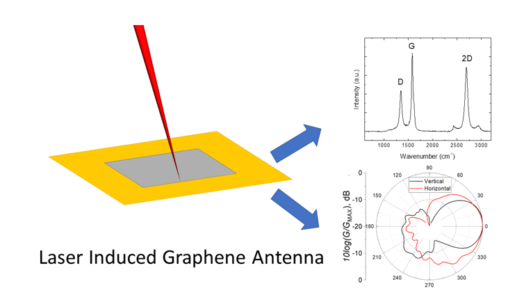
27]. LIG is lightweight and flexible. This flexibility allows for integrating LIG antennas into curved surfaces or wearable electronics, expanding their potential applications. The lightweight nature of LIG also minimizes the overall weight of devices, which is crucial for portable and lightweight electronics. This flexibility in LIG integration enables the development of innovative antenna designs and complex electronic systems. These benefits make LIG a promising material for advancing the performance and functionality of antennas and electronic devices. Therefore, this research presents our initial study of the LIG-PI application for a 2.45 GHz patch antenna working in the WiFi range.
2. Materials and Methods
2.1. Samples
Our experiments utilized Polyimide Kapton® films manufactured by DuPont, USA, with a thickness measuring 127 μm.
2.1. Resistance measurement
Sheet resistance measurements were performed using the source meter (Keithley 2602A, Keithley, USA) with the measurement software (TSP® Express, Keithley, USA). Messurements were performed using 4 probe method technique[
28]. Four co-linear electrical probes that are identically spaced form a four-point probe. To operate, a DC current (I) is applied between the outer two probes, and the voltage drop between the inner two probes is then measured. The following equation can then be used to get the sheet resistance:
Rs is the sheet resistance, ΔV is the change in voltage measured between the inner probes, and I is the current applied between the outer probes.
2.1. Raman measurements
The Raman spectrometer/microscope inVia (Renishaw, UK) was utilized for conducting Raman spectroscopic measurements. Equipped with a thermoelectrically cooled CCD detector at -70°C, the spectrometer excited the spectra through 532 nm laser irradiation dispersed by 1800 grooves/mm grating. The measurements were performed using a 50x/0.75NA objective lens, 100 s accumulation time, and the resulting spectral peaks were processed using OriginPro 8.5 software from Microlab, USA.
2.2. Antenna measurement
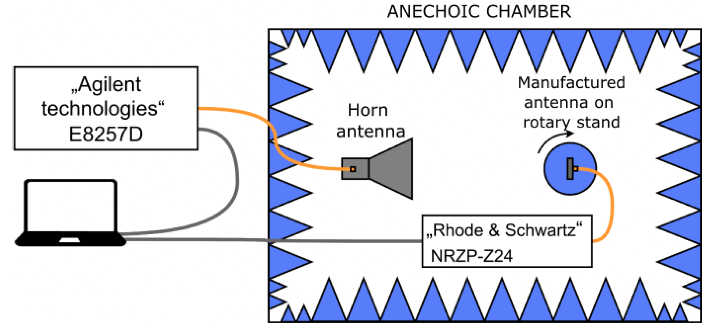
The following parameters were measured to evaluate manufactured antennas: Reflection coefficient, operating frequency, maximum gain, half-power beam width and surface conductivity. Gain and directivity parameters were measured in an anechoic chamber. The measurement setup is explained in
Figure 1. The antenna under investigation is placed on a rotation stand that can be rotated 360° by a stepping motor. The excitation port of an antenna is connected to a calibrated NRZP-Z24 (Rhode & Schwartz, Germany) power meter. The power meter is connected to a PC via a USB cable. A broadband horn antenna with known specifications is positioned 2 m away from the transmitting antenna (far-field). The horn antenna is connected to an E8257D (Agilent technologies, USA) programmable radio signal generator through a coaxial connection. The stand, power meter, and signal generator are all controlled by a LabVIEW (NI, USA) program.
The frequency response is measured by keeping the power of the signal fed to the horn antenna constant (20 dBm) and changing frequency from 2 GHz to 3 GHz in 0.01 GHz increments. Gain dependence on an angle is measured by setting the power constant (20 dBm), locking frequency at 2.45 GHz, and rotating the stand from 0° to 360° in 3° increments. Then, using a formula (2) derived from Telegraph equations, the gain is calculated:
here
P – measured power,
R – the distance between antennas,
PTR – transmitted power,
GTR – transmitting antenna gain, λ – wavelength.
For more straightforward data interpretation, we normalized the gain measurements using the following formula:
here G
MAX – is the highest gain measured, G – is the measured gain at angle or frequency.
The antenna is also characterized by the frequency dependence of the reflection, which describes the matching quality between the antenna and its excitation port (which is 50 Ω). For this purpose, a vector network analyzer is used.
3. Results and Discussion
3.1. Influence of laser process parameters on LIG sheet resistance and Raman spectra
Our initial tests showed that varying laser process parameters could control sheet resistance. Therefore we picked 1064 nm picosecond laser irradiation as it showed a relatively wide range of parameters, using which high-quality LIG can be formed. Furthermore, Chyan et al.[
29] showed that LIG formation multiple lasing – repeating irradiation – is crucial to achieving high-quality LIG material. In other words, specific fluence and sufficient laser irradiation dose are required to form LIG.
During our laser tests, the laser scanning speed was kept at 200 mm/s, and the irradiation dose was varied by changing the average laser power (4 and 5 W), varying the sample position according to the focal plane of the focusing objective: at the focus and 1 mm above, and finally by the number of scanning times (2 and 3). The radiation dose assessment involved the multiplication of laser fluence with the total number of pulses within the beam spot area.
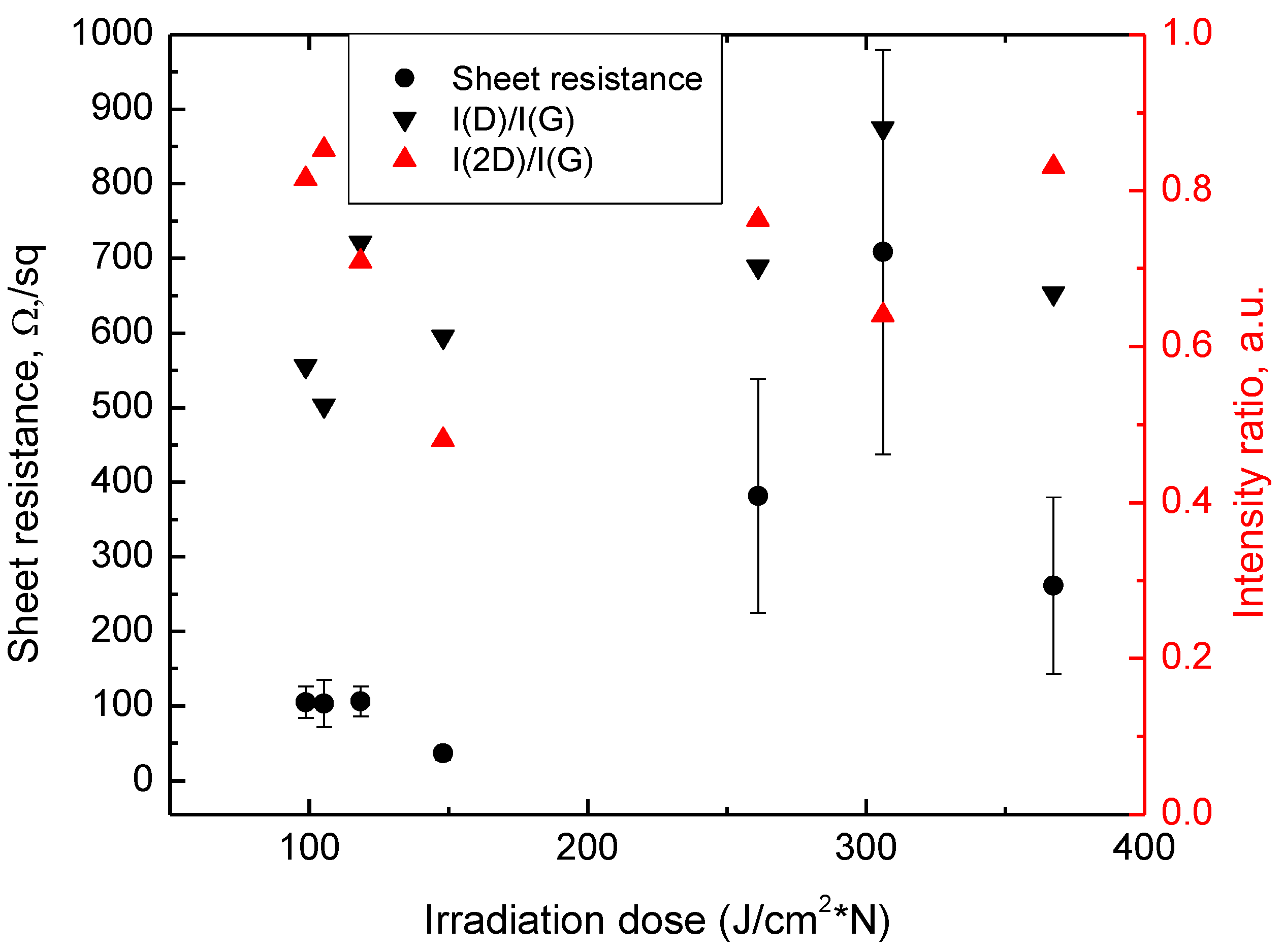
Figure 2 shows the dependence of sheet resistance from this accumulated irradiation dose. It is worth noticing that when the irradiation dose is in the range of 90-150 J/cm
2*N, the sheet resistance is around 100 Ω/sq and smaller with significantly smaller measured values distribution compared to the ones measured at irradiation dose greater than 150-150 J/cm
2*N. It is also worth noticing that all the lowest LIG sheet resistance values were achieved while LIG was processed with a defocused beam (1 mm above the focal plane of the focusing objective.
The I(D)/I(G) ratio is the intensity ratio between the D and G peaks in graphene Raman spectra. The D peak represents defects or disorders in the graphene lattice, while the G peak corresponds to the graphite-like lattice vibrations. Therefore, a higher I(D)/I(G) ratio indicates a higher degree of defects or disorder in the graphene structure.
On the other hand, the
I(2D)/I(G) ratio represents the intensity ratio between the 2D peak and the G peak. The 2D peak is associated with the second-order Raman scattering and is a characteristic feature of graphene. The
I(2D)/I(G) ratio determines the number of graphene layers. A higher
I(2D)/I(G) ratio suggests enhanced graphene quality: High-quality graphene with a well-ordered lattice structure typically displays a higher
I(2D)/I(G)) ratio. Conversely, lower-quality graphene samples, such as those with a higher degree of disorder, defects, or impurities, tend to have lower
I(2D)/I(G) ratios. These ratios provide insights into a sample's quality, structural integrity, and number of graphene layers.
Figure 1 presents the distribution of Raman spectra intensity ratios
I(D)/I(G) and
I(2D)/I(G), and their values at different irradiation doses are plotted.
It is worth noticing that through the whole range of tested irradiation doses, we succeeded in successful high-quality LIG formation, which is confirmed by high I(2D)/I(G) ratio, higher than 0.5. However, the highest I(2D)/I(G) values representing high-quality graphene structure together with the lowest I(2D)/I(G) values representing the lower number of LIG structural defects were measured with LIG samples formed with low irradiation dose. As mentioned before, this particular processing regime included defocusing the laser beam. Therefore, with a higher beam diameter, the multiple lasing effect was more prominent, resulting in the formation of high-quality LIG—furthermore, a defocused laser beam induced the lowest resistance due to lower laser beam intensity. Therefore lower ablation rates and nonlinear effects like multiple photon absorptions occur rarely during the process. The process thus affected more thermally, leading to graphene formation.
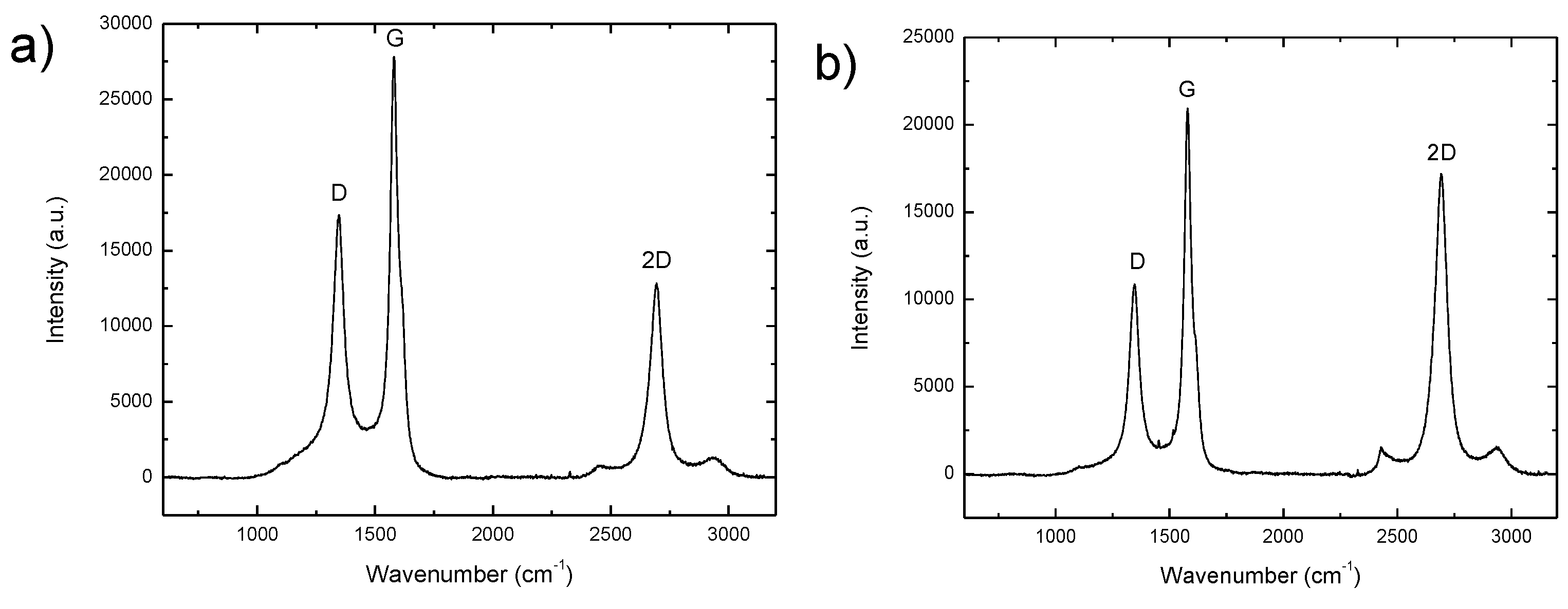
Figure 3 a) shows the Raman spectre of the LIG with the smallest resistance of 36.6 Ω/sq. This LIG structure was formed using a 148 J/cm
2*N irradiation dose. The main peaks prominent for the graphene Raman spectra are visible.
I(2D)/I(G) is 0.61 and
ID)/I(G) is 0.48. However, the largest
I(2D)/I(G) ratio of 0.85 was achieved when PI was processed at 105 J/cm
2*N irradiation dose and possessed the sheet resistance of 105 Ω/sq (
Figure 3b). On the other hand
I(D)/I(G) ratio showing structural defect was slightly lower, with a value of 0.52. Further investigations of LIG antenna were performed using the laser process parameters from
Figure 3a with the lowest sheet resistance.
3.2. LIG antenna measurements
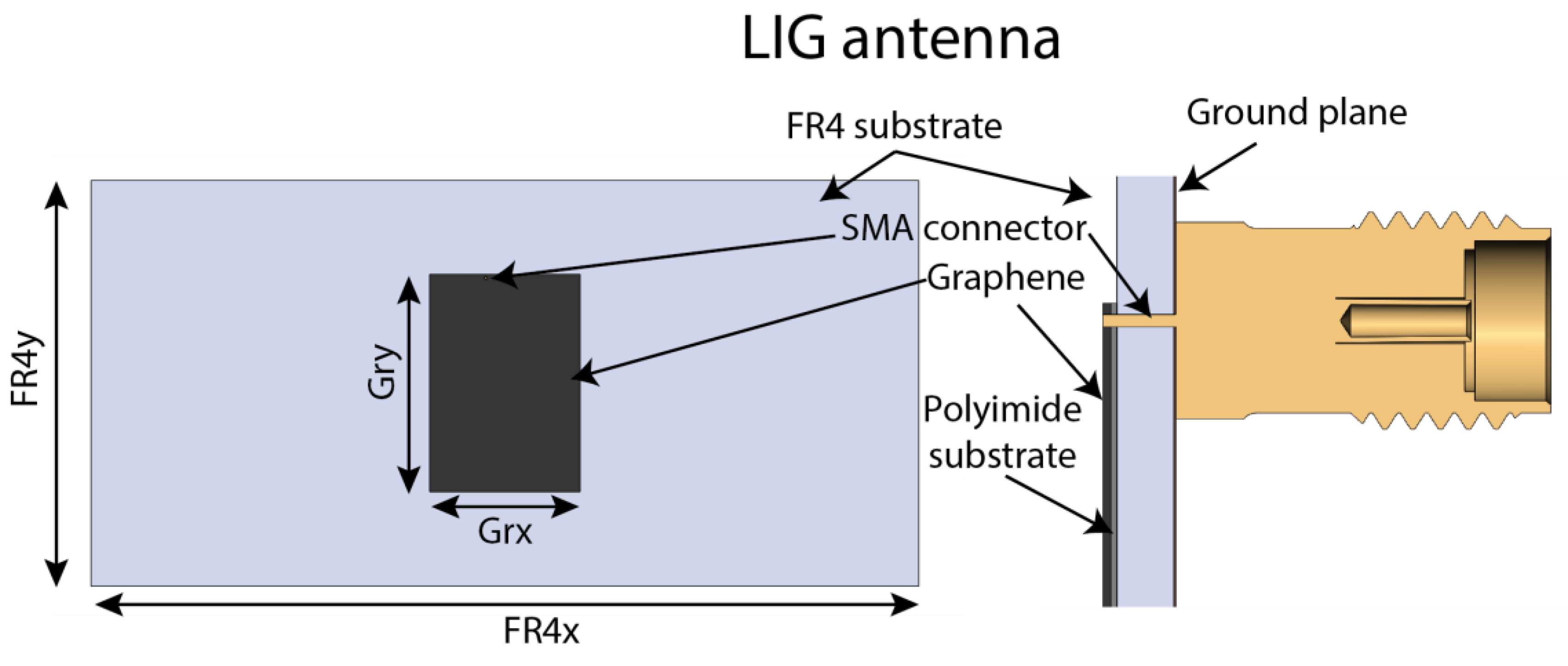
In order to demonstrate the possibility of using laser-induced graphene for microwave antenna application, we modelled a microwave patch antenna shown in
Figure 4. The antenna is made of FR-4 substrate (tanδ = 0.03) with a thickness of 1.45 mm and ε = 4.2. One side of the FR4 substrate is completely covered with a thin copper layer and forms the ground plane of the antenna. The dimensions of the FR4 substrate are FR4x = 110 mm and FR4y = 54 mm. The LIG on the polyimide is glued on the other side of the substrate. The thickness of the polyimide is approximately 130 μm), and the LIG layer's thickness is around 10 μm). The dimensions of LIG patch are GRx = 20 mm and GRy = 29 mm. The LIG patch is placed in the middle of the FR4 substrate. During antenna modelling, the best patch size and the place of the SMA connector were found to have the smallest S11 and highest antenna gain.
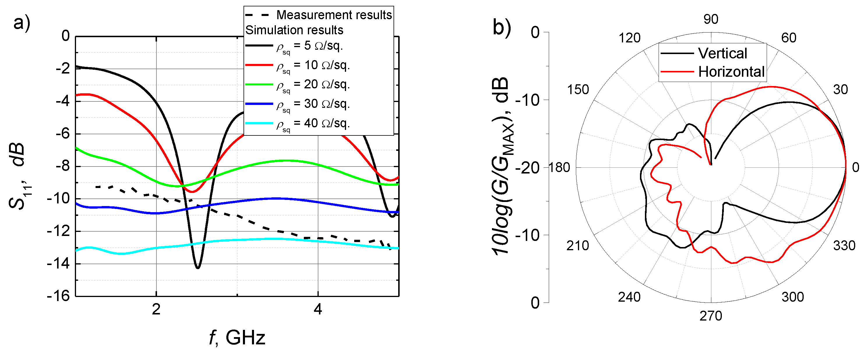
Reflection and normalized directivity measurements were used to characterize a graphene antenna, which are shown in
Figure 5. Looking at measured reflection dependence on frequency, the antenna appears to have a reasonably broad operating frequency band. The reflection coefficient is below -10 dB from 2.1 GHz and continues to decrease to -13 dB at 5 GHz. This does not match the typical patch antenna behaviour. LIG's low conductivity might cause a mismatch compared to traditionally used copper. This phenomenon was investigated by changing patch sheet resistance in the antenna model using antenna simulation software (
Figure 5 a). Simulation results show that when the LIG sheet resistance is low, the antenna acts like a regular patch antenna and has a reflection minimum at intended frequencies (2.45 GHz). When the sheet resistance of LIG layer increases, the resonance disappears and the reflections in the whole frequency range decrease. This could be explained due to internal losses in the LIG layer. The simulation of the results coincides best with the measured S11 when the sheet resistance is around 30 – 40 Ω/sq. Similar sheet resistance is obtained by performing four-probe measurements. Directivity measurement showed that the radiation pattern resembles a traditional patch antenna. Antenna beamwidth is 63° in a vertical position and 80° in a horizontal position.
5. Conclusions
Successful LIG formation was performed in a wide range of laser irradiation doses and was confirmed by Raman spectroscopy - I(2D)/I(G) was higher than 0.5. Sheet resistance was smallest at irradiation doses from 98 to 148 J/cm2*N when PI sample was irradiated at the position 1 mm above the focal plane of the focusing objective. The minimal sheet resistance of LIG was 36.6 Ω/sq. Using optimal process parameters patch antenna for 2.45 GHz (WiFi) was produced and investigated.
The results of patch antenna with LIG layer show promising results as one of the alternative methods for green and sustainable solutions for manufacturing removable and flexible antennas. Thou, additional investigations still need to be performed to reduce LIG layer sheet resistance and increase antenna efficiency.
6. Patents
Not applicable
Author Contributions
Conceptualization, P.R., K.R. and R.T.; methodology, A.S., JZ. P.R. and R.T..; software, P.R..; validation, A.S., J.Z. P.R. K.R.. and R.T,.; formal analysis, A.S. and J.Z.; investigation, P.R., K.R. and R.T.; writing—original draft preparation, P.R. and R.T.; writing—review and editing, R.T.; visualization, P.R. and R.T..; supervision, R.T.; project administration, K.R. and R.T. All authors have read and agreed to the published version of the manuscript.
Funding
This project has received funding from European Regional Development Fund (project BEGAMA No 01.2.2-LMT-K-718-03-0038) under grant agreement with the Research Council of Lithuania (LMTLT).
Data Availability Statement
The data supporting this study's findings are available from the corresponding author upon reasonable request.
Acknowledgments
Authors are grateful to Dr. Martynas Talaikis for accessing Raman spectroscopy at the Laboratory of Spectroelectrochemistry of the Department of Organic Chemistry (FTMC, Lithuania).
Conflicts of Interest
The authors declare no conflict of interest.
References
- Wanjari, V.P.; Reddy, A.S.; Duttagupta, S.P.; Singh, S.P. Laser-Induced Graphene-Based Electrochemical Biosensors for Environmental Applications: A Perspective. Environmental Science and Pollution Research 2023, 30, 42643–42657. [Google Scholar] [CrossRef] [PubMed]
- Liu, H.; Chen, Y. Laser-Induced Graphene Film and Its Applications in Flexible Electronics. Applied Sciences 2022, 12. [Google Scholar] [CrossRef]
- Vivaldi, F.M.; Dallinger, A.; Bonini, A.; Poma, N.; Sembranti, L.; Biagini, D.; Salvo, P.; Greco, F.; Di Francesco, F. Three-Dimensional (3D) Laser-Induced Graphene: Structure, Properties, and Application to Chemical Sensing. ACS Appl Mater Interfaces 2021, 13, 30245–30260. [Google Scholar] [CrossRef]
- Barber, R.; Cameron, S.; Devine, A.; McCombe, A.; Kirsty Pourshahidi, L.; Cundell, J.; Roy, S.; Mathur, A.; Casimero, C.; Papakonstantinou, P.; et al. Laser Induced Graphene Sensors for Assessing PH: Application to Wound Management. Electrochem commun 2021, 123, 106914. [Google Scholar] [CrossRef]
- Peng, Z.; Lin, J.; Ye, R.; Samuel, E.L.G.; Tour, J.M. Flexible and Stackable Laser-Induced Graphene Supercapacitors. ACS Appl Mater Interfaces 2015, 7, 3414–3419. [Google Scholar] [CrossRef]
- Kulyk, B.; Silva, B.F.R.; Carvalho, A.F.; Silvestre, S.; Fernandes, A.J.S.; Martins, R.; Fortunato, E.; Costa, F.M. Laser-Induced Graphene from Paper for Mechanical Sensing. ACS Appl Mater Interfaces 2021, 13, 10210–10221. [Google Scholar] [CrossRef]
- Stanford, M.G.; Zhang, C.; Fowlkes, J.D.; Hoffman, A.; Ivanov, I.N.; Rack, P.D.; Tour, J.M. High-Resolution Laser-Induced Graphene. Flexible Electronics beyond the Visible Limit. ACS Appl Mater Interfaces 2020, 12, 10902–10907. [Google Scholar] [CrossRef] [PubMed]
- Trusovas, R.; Ratautas, K.; Račiukaitis, G.; Barkauskas, J.; Stankevičiene, I.; Niaura, G.; Mažeikiene, R. Reduction of Graphite Oxide to Graphene with Laser Irradiation. Carbon N Y 2013, 52, 574–582. [Google Scholar] [CrossRef]
- Wei, Z.; Wang, D.; Kim, S.; Kim, S.Y.; Hu, Y.; Yakes, M.K.; Laracuente, A.R.; Dai, Z.; Marder, S.R.; Berger, C.; et al. Nanoscale Tunable Reduction of Graphene Oxide for Graphene Electronics. Science (1979) 2010, 328, 1373–1376. [Google Scholar] [CrossRef]
- Kumar, P.; Subrahmanyam, K.S.; Rao, C.N.R. Graphene Produced by Radiation-Induced Reduction of Graphene Oxide. Int J Nanosci 2011, 10, 559–566. [Google Scholar] [CrossRef]
- Sokolov, D.A.; Shepperd, K.R.; Orlando, T.M. Formation of Graphene Features from Direct Laser-Induced Reduction of Graphite Oxide. Journal of Physical Chemistry Letters 2010, 1, 2633–2636. [Google Scholar] [CrossRef]
- Sokolov, D.A.; Rouleau, C.M.; Geohegan, D.B.; Orlando, T.M. Excimer Laser Reduction and Patterning of Graphite Oxide. Carbon N Y 2013, 53, 81–89. [Google Scholar] [CrossRef]
- Trusovas, R.; Račiukaitis, G.; Barkauskas, J.; Mažeikienë, R. Laser Induced Graphite Oxide/Graphene Transformation. Journal of Laser Micro Nanoengineering 2012, 7. [Google Scholar] [CrossRef]
- Ye, R.; James, D.K.; Tour, J.M. Laser-Induced Graphene. Acc Chem Res 2018, 51, 1609–1620. [Google Scholar] [CrossRef]
- Luong, D.X.; Yang, K.; Yoon, J.; Singh, S.P.; Wang, T.; Arnusch, C.J.; Tour, J.M. Laser-Induced Graphene Composites as Multifunctional Surfaces. ACS Nano 2019, 13, 2579–2586. [Google Scholar] [CrossRef] [PubMed]
- Lin, J.; Peng, Z.; Liu, Y.; Ruiz-Zepeda, F.; Ye, R.; Samuel, E.L.G.; Yacaman, M.J.; Yakobson, B.I.; Tour, J.M. Laser-Induced Porous Graphene Films from Commercial Polymers. Nat Commun 2014, 5, 1–8. [Google Scholar] [CrossRef]
- Lin, J.; Peng, Z.; Liu, Y.; Ruiz-Zepeda, F.; Ye, R.; Samuel, E.L.G.; Yacaman, M.J.; Yakobson, B.I.; Tour, J.M. Laser-Induced Porous Graphene Films from Commercial Polymers. Nat Commun 2014, 5, 5–12. [Google Scholar] [CrossRef]
- Lopes, D. V.; Santos, N.F.; Moura, J.P.; Fernandes, A.J.S.; Costa, F.M.; Kovalevsky, A. V. Design of Laser-Induced Graphene Electrodes for Water Splitting. Int J Hydrogen Energy 2023, 48, 4158–4172. [Google Scholar] [CrossRef]
- Trusovas, R.; Ratautas, K.; Račiukaitis, G.; Niaura, G. Graphene Layer Formation in Pinewood by Nanosecond and Picosecond Laser Irradiation. Appl Surf Sci 2019, 471. [Google Scholar] [CrossRef]
- Fiodorov, V.; Ratautas, K.; Mockus, Z.; Trusovas, R.; Mikoliūnaitė, L.; Račiukaitis, G. Laser-Assisted Selective Fabrication of Copper Traces on Polymers by Electroplating. Polymers (Basel) 2022, 14. [Google Scholar] [CrossRef]
- Ruan, X.; Wang, R.; Luo, J.; Yao, Y.; Liu, T. Experimental and Modeling Study of CO2 Laser Writing Induced Polyimide Carbonization Process. Mater Des 2018, 160, 1168–1177. [Google Scholar] [CrossRef]
- Ma, L.; Wang, Y.; Wang, Y.; Wang, C.; Gao, X. Graphene Induced Carbonization of Polyimide Films to Prepared Flexible Carbon Films with Improving-Thermal Conductivity. Ceram Int 2020, 46, 3332–3338. [Google Scholar] [CrossRef]
- In, J. Bin; Hsia, B.; Yoo, J.H.; Hyun, S.; Carraro, C.; Maboudian, R.; Grigoropoulos, C.P. Facile Fabrication of Flexible All Solid-State Micro-Supercapacitor by Direct Laser Writing of Porous Carbon in Polyimide. Carbon N Y 2015, 83, 144–151. [Google Scholar] [CrossRef]
- Wang, S.; Yu, Y.; Li, R.; Feng, G.; Wu, Z.; Compagnini, G.; Gulino, A.; Feng, Z.; Hu, A. High-Performance Stacked in-Plane Supercapacitors and Supercapacitor Array Fabricated by Femtosecond Laser 3D Direct Writing on Polyimide Sheets. Electrochim Acta 2017, 241, 153–161. [Google Scholar] [CrossRef]
- Wang, L.; Wang, Z.; Bakhtiyari, A.N.; Zheng, H. A Comparative Study of Laser-Induced Graphene by CO2 Infrared Laser and 355 Nm Ultraviolet (UV) Laser. Micromachines (Basel) 2020, 11. [Google Scholar] [CrossRef] [PubMed]
- Abdul-Aziz, M.R.R.; Mohassieb, S.A.; Eltresy, N.A.; Yousef, M.M.K.; Anis, B.; Abdellatif, S.O.; Khalil, A.S.G. Enhancing the Performance of Polygon Monopole Antenna Using Graphene/TMDCs Heterostructures. IEEE Trans Nanotechnol 2020, 19, 269–273. [Google Scholar] [CrossRef]
- Ahmad, M.; Cantarella, G.; Angeli, M.A.C.; Madagalam, M.; Ebner, C.; Ciocca, M.; Riaz, R.; Ibba, P.; Petrelli, M.; Merino, I.; et al. 2. In 4 GHz Microstrip Patch Antenna Fabricated by Means of Laser Induced Graphitization of a Cellulose-Based Paper Substrate. In Proceedings of the 2021 IEEE International Flexible Electronics Technology Conference (IFETC); August 2021; pp. 44–46. [Google Scholar]
- Smits, F.M. Measurement of Sheet Resistivities with the Four-Point Probe. The Bell System Technical Journal 1958, 37, 711–718. [Google Scholar] [CrossRef]
- Chyan, Y.; Ye, R.; Li, Y.; Singh, S.P.; Arnusch, C.J.; Tour, J.M. Laser-Induced Graphene by Multiple Lasing: Toward Electronics on Cloth, Paper, and Food. ACS Nano 2018, 12, 2176–2183. [Google Scholar] [CrossRef]
|
Disclaimer/Publisher’s Note: The statements, opinions and data contained in all publications are solely those of the individual author(s) and contributor(s) and not of MDPI and/or the editor(s). MDPI and/or the editor(s) disclaim responsibility for any injury to people or property resulting from any ideas, methods, instructions or products referred to in the content. |
© 2024 by the authors. Licensee MDPI, Basel, Switzerland. This article is an open access article distributed under the terms and conditions of the Creative Commons Attribution (CC BY) license (https://creativecommons.org/licenses/by/4.0/).
