

Submitted:
12 May 2023
Posted:
12 May 2023
You are already at the latest version
Abstract
This paper investigates the classical but yet intriguing question of modeling orthotropic RC floor systems endowed with lightening elements, by means of a uniform orthotropic slab, in order to describe accurately the building response under seismic loads. The simplified method, commonly adopted by engineers, based on the equivalence between the transverse stiffness of the RC elements of the real floor and those of the orthotropic slab is presented. A case study in which this simplified method is used is also provided. Then, an advanced finite elements (FE) based method to determine the elastic properties of the equivalent homogenized orthotropic slab is proposed. Based on the results obtained from the application of this method to a case study, a discussion on the adequacy of the simplified method is also provided.
Keywords:
RC floors
; orthotropic floors
; lightening elements
; shell element
; in-plane deformability
; finite element model
; homogenization method
1. Introduction
The structural behavior of Reinforced Concrete (RC) buildings under seismic actions is influenced by floors in-plane stiffness, which has a crucial role in the distribution of inertia forces to vertical structural elements. Such distribution of forces does not depend on the absolute floor stiffness but rather by the ratio between the floor stiffness and the lateral stiffness of vertical elements [1].
In order to guarantee that inertia forces arising in the building distribute among vertical resistant elements proportionally to their lateral stiffness, modern Building Codes recommend that floors subject to seismic actions are designed to behave as rigid diaphragms.
The main geometric factors influencing floor in-plane stiffness are the floor thickness and shape ratio (length/width), the building plan geometry (i.e. rectangular, U-shaped or L-shaped), the presence of openings within the floor and the position of shear walls in the building plan [2,3,4,5].
The main worldwide Building Codes [6,7,8,9,10,11,12,13] provide qualitative and quantitative criteria to evaluate the adequacy of rigid floor hypothesis. Qualitative criteria are primarily related to the shape of the diaphragm, while quantitative criteria set bounds to the in-plane deformation of the diaphragm. For instance, the Italian Code imposes to check the rigid floor assumption when the building has elongated or non-compact shaped plan, or in presence of shear walls with high lateral stiffness [8]. It also states that diaphragms can be considered infinitely rigid if, modeling their actual in-plane flexibility, the horizontal displacements nowhere exceed those resulting from the rigid diaphragm assumption by more than 10% of the corresponding absolute horizontal displacements.
In existing Italian RC buildings, the most widespread floor typologies are the one-way joist systems made by a monolithic combination of regularly spaced ribs (joists) and a top slab with permanent light weight fillers (usually hollow bricks) between the ribs.
For this floor system, the Code imposes that the rigid floor assumption can be adopted only if the slab thickness is not smaller than 40 mm. In existing buildings, designed only for gravity loads, this condition is not always satisfied, as it occurs in the two case-studies analyzed in [14]. Moreover, it’s not unusual to deal with buildings having high length-to-width ratios [15], in-plan irregular structural patterns and/or with shear walls not uniformly distributed within the building plan [14]. For such buildings, the in-plane floor deformability could determine a larger demand of both strength and ductility to some structural elements, compared to the case of rigid floors [16,17,18,19,20,21,22].
In all the mentioned cases the actual in-plane floor deformability may be not negligible. Furthermore, also for buildings seismically retrofitted with external stiffening frames, connected to the building structure along the perimeter, it may be necessary to take account of the effect of floor in-plane deformability, to correctly evaluate the intervention effectiveness.
For the seismic analysis of buildings, 3D FE models realized with frame and shell elements are commonly used, due to their practicality and computational efficiency. In these models the floors are represented by equivalent uniform orthotropic slabs discretized by shell elements with a prevalent membrane behavior (the bending plate part of the shell is not important). In the case of one-way joist floor systems which have in-plane orthotropic behavior, it is necessary determine the mechanical properties of the equivalent orthotropic slabs.
In practice, the method based on the equivalence between the transverse stiffness (in two orthogonal plane directions) of the RC elements of the real floor and that of the orthotropic slab is commonly adopted by engineers. This simplified analytical-based method does not consider the in-plane shear stiffness equivalence between the real floor and the orthotropic slab. If the shell elements thickness is set equal to that of the RC floors’ slab, the in-plane shear stiffness is given by the product of its thickness and the shear elastic modulus of the concrete. The effect of RC joists and lightening elements on floors shear in-plane stiffness is completely neglected. A particular case-study in which this method is suitable to reproduce floors in-plane deformability is covered in subsection 2.2.
Although the importance of correctly evaluating the in-plane floor stiffness is well-recognized, in the literature the studies proposing an operational method to derive the mechanical properties of equivalent slab are few [23,24]. Actually, most of the research works dealing with in-plane floor deformability investigate the main factors influencing the relevance of floor deformability effects on the building structural behavior. These factors are: the building plan shape, the floor length-to-width ratio, the ratio between the building height and the floor length, the number of stories and the position of shear walls ([1,2,3,4,5] and [16,17,18,19,20,21,22,23,24,25,26,27,28]).
In both the research works presented in [23] and [24], proposing a method to derive the properties of the equivalent shell elements, a numerical approach is adopted. In these works, the equivalent thicknesses of shell elements in their main directions [23] or the equivalent material compressive elastic moduli [24] are determined from the comparison of two FE models of the floor: the first realized with solid elements and the second with shell elements. The displacements induced by horizontal loads are used as comparison parameters. In both research works the floor in-plane bending behavior is investigated in presence of distributed horizontal forces applied to the floor edge. Seeking the equality of the maximum displacements of the two FE models [23] or the maximum to minimum in-plane displacements ratio [24], the properties of the equivalent slab are found through an iterative method.
Both the proposed numerical methods do not take into account how the interaction between shell-type elements and frame-type elements, used to reproduce the frame structure, takes place in the 3D FE model of the building.
In section 4, a numerical method to determine the linear elastic properties of the equivalent homogenized orthotropic slab, taking into account the interaction of shell elements with frame elements, is proposed. The equivalence between the in-plane stiffness of the orthotropic slab and that of the real orthotropic floor is assessed on the basis of the solid FE model of the floor.
2. Simplified analytical-based method
2.1. Method
In practice, to reproduce the in-plane deformability of orthotropic floors, engineers usually take account of the orthotropy by adopting shell elements having different in-plane (membrane) stiffness in the main directions, and neglecting the contribution of lightening elements. Consequently, the stiffness in the joists’ direction, , is obtained by imposing the equality between the transverse stiffness of shell elements and that of floor RC elements (i.e. the joists and the slab). In the orthogonal direction, the in-plane stiffness is usually taken equal to that of the floor RC slab, neglecting any contribution of joists.
Such procedure basically derives from the schematization of floor constitutive elements through single Degrees Of Freedom (DOF) springs with elastic axial stiffness equal to that of each element. The in-plane axial stiffness of the equivalent 2D element is obtained by the sum of the elastic axial stiffness of the springs representing each floor element. Naming , and the axial stiffness of the slab, the joists and the lightening elements respectively, the value of is determined as
where the springs stiffness are evaluated by the product of the Young’s modulus of the material and the cross-section area of the element. Naming and the Young’s moduli of the concrete and lightening elements, respectively, and , and the transverse area of the slab, the joists and the lightening elements, respectively, equation (1) becomes
and, neglecting the contribution of lightening elements
Similarly, the value of is determined as
If the thickness of the shell elements is set equal to that of the RC floor slab, the in-plane stiffness of the shell element in the direction orthogonal to joists is just equal to . But, so doing, also the stiffness in the joist direction would be equal to . Hence a stiffness modifier is commonly used in the applications chosen so that
Since the in-plane shear stiffness equivalence is not forced, the equivalent shell element may not be suitable to reproduce the actual in-plane stiffness of floors under seismic actions. However, the simplified method can certainly be useful in those cases in which floors are subjected to constant axial stresses along the edges. This situation may occur, for instance, in inclined roof floors under static loads.
In the next subsection, the effect of floors in-plane stiffness on the forces arising in the structural elements of a real case study with inclined floors, subject to gravitational loads, is investigated.
2.2. Case study
2.2.1. Description
Let us consider the roof of an existing RC building used for sporting activities. The FE model of the roof made using the software SAP2000 [29] is shown in Figure 1.
The roof plane is bounded by two straight parallel lines in one direction and by two circumference arcs in the transverse direction. Considering a reference system with the origin located at the center of the circumference to which, ideally, the curved edges belong to, the X axis is taken parallel to the straight sides while the Y axis is orthogonal to X. Along X and Y the roof has dimensions of about 34x18 m2.
The bearing structure of the roof is made by 24 trusses disposed radially with respect to the origin of the reference axes, and equiangular. The trusses are, in their turn, composed of three structural elements, a top beam, an inclined bottom chord and a vertical strut, connected to each other to form a triangular static scheme. The top beam has a slight 2.5% slope with respect to the horizontal plane.
The top beam is made by a composite steel-concrete element (Figure 2), with a HEA200 profile connected on the top to a rectangular cross-section RC element, of dimensions 60x22 cm2. The connection is made by steel U-shaped connectors welded to the top flange of steel profiles along its whole length. The inclined bottom chords and the vertical struts are, instead, made by circular hollow steel profiles having diameter of 9 cm and thickness of 6.5 mm.
Along the perimeter of the building, the radial trusses are connected to the RC perimeter beams in correspondence of the nodes between the top beam and the bottom chord (Figure 1), where one of these nodes is circled in red. In the center of the roof, the nodes between the bottom chord and the vertical strut of trusses are connected to each other by 24 steel profiles, constituting a polygonal truss lying in a horizontal plane. In Figure 1 one of these nodes is highlighted by a green circle. These profiles have the same cross-section of vertical struts and bottom chords. Conversely, the nodes between the top beam and the vertical strut, one of which is circled in black in Figure 1, are connected to each other by a circular-shaped RC beam (emergent beam in Figure 1), having rectangular cross-section of dimensions 40x140 cm2. In this beam there are 16 square holes of side 50 cm.
Moreover, the nodes between the top beams and the vertical struts are connected to the bottom nodes of the adjacent beams belonging to the polygonal truss by means of diagonal ties, constituted by steel bars with 20 mm diameter, which are represented in red in Figure 3.
The effect exerted by RC perimeter beams of the building on the radial trusses is modelled through restraints that prevent translations along the axial direction of the perimeter beams, assuming inextensible these beams. These restraints prevent also the translations along the vertical direction, due to the high flexural stiffness of perimeter beams towards vertical loads. Conversely, translations orthogonal to the perimeter beams axis are allowed, due to the finite flexural stiffness of the perimeter beams under bending actions in the horizontal plane.
The roof is constituted by 24 floor cells, each of which is bounded by the top beams of two adjacent radial trusses and by the portions of the perimeter beam and the circular-shaped RC beam between the considered radial trusses. The floors are made of precast slabs of predalles type with polystyrene lightening elements placed above, completed by casted in-place RC joists with a slab on the top. Predalles slabs are 4 cm thick and 120 cm wide, and are installed with their longitudinal axis orthogonal to the bisector of the angle between the longitudinal axes of the radial trusses bounding the floor cell, resting on the bottom flanges of HEA200 profiles. Their length varies in function of their position, and it is equal to the average distance between the radial trusses supporting them (Figure 2). Joists are 8 cm high and 12 cm or 24 cm wide, depending on whether they are located in the mid span of predalles slab or straddling two consecutive predalles slabs, respectively. The spacing between the joists is equal to 60 cm. From the above it can be gathered that the dimensions of lightening elements in the floor cross-section are 42x8 cm2. The top flanges of HEA200 profiles are fully embedded in the topping RC slab of the floor and the transverse reinforcement of the slab passes over the flanges, as shown in Figure 2. Hence the slab is continuous all over the roof surface bounded by the perimeter beams and the circular-shaped RC beam.
Due to the presence of a space between adjacent bottom predalles slabs (Figure 4), they are not in contact along their longitudinal edges. As a consequence, bottom predalles slabs do not contribute to the transmission of compression or tensile stresses along the direction orthogonal to their longitudinal axis. Therefore, their contribution to axial in-plane stiffness of floors along the circumferential direction is null.
A steel framed structure with 16-edge pyramidal shape and cellular polycarbonate panels is anchored to the top side of the circular-shaped RC beam, serving as a covering of the central hole.
Under the gravitational loads, the circular-shaped RC beam and the radial trusses undergo to downward vertical displacements. Due to the radial configuration of the roof bearing structure, and to translations of the radial trusses ends at the connection with the perimeter beams orthogonally to the perimeter beams’ axis, in the horizontal plane, the points at the bottom of the circular-shaped RC beam undergo to radial horizontal displacements. In particular, these displacements are outward (from the center) for the beam portions connected to the shorter radial trusses and inward for those connected to the longer radial trusses. At the same time, the ends of the radial trusses connected to the perimeter beams move outward, orthogonally to the perimeter.
Due to the kinematic behavior of the bearing structure, the floors are subject to in-plane stress states. Hence, floors, due to their in-plane stiffness, interact with the roof bearing structure, influencing its deformed shape and, thus, the forces arising in structural elements. In particular, the stress state arising in each floor cell is mainly constituted of axial stresses in both the main directions of the floor, while in plane shear stresses are negligible. As a consequence the simplified method described in section 2.1 can be adopted to determine the in-plane transverse stiffness of the equivalent shell elements in their main directions, in order to reproduce effectively the actual in plane-stiffness of floor cells.
2.2.2. Determination of shell elements properties through the simplified method
The thickness of the shell elements used to reproduce the in-plane deformability of floors is set equal to 8 cm, as that of the upper slab of the roof. The in-plane stiffness of the shell elements in the joists’ direction, derived from equation (3) by adding the contribution of predalles slab area , is
Considering a floor strip of unit width, by imposing (5) we get the stiffness modifier
where and are the joists and predalles slab thickness, respectively, while is the number of joists in the unit strip. For the case study it is found = 1.8.
Conversely, in the direction orthogonal to joists the only contribution to the in-plane floor stiffness is provided by the top RC slab. Actually, predalles slabs are not able to contribute to the transmission of axial stresses because of the physical discontinuity between two adjacent slabs. Hence, the in-plane stiffness of the equivalent 2D elements coincides with that of the real floor.
2.2.3. Results
The effect of floor in-plane stiffness, accounted by shell elements determined as described in section 2.2.2, is investigated under the gravitational loads. In the FE model, the cracking effect on beams flexural stiffness is accounted by using properly reduced second moments of area. Also the long-term effects of concrete creep are taken into account, through a reduced value of .
From the results of the analyses of the two FE models, with and without the equivalent 2D elements, it is observed that the most relevant effect is on stresses acting in the circular-shaped RC beam. In presence of shell elements, stresses are about 15% lower than those obtained from the FE model that does not take into account the floor in-plane stiffness.
With regard to the internal forces (normal compression and bending moment) in the top beams of the radial trusses, it is derived that accounting floor in-plane stiffness induces a slight reduction of stresses of about 7% both in the concrete and in HEA200 steel profiles.
3. Theoretical basis
The nodes at beams intersection, in the FE model of the one-way joists floor, are called, in the following, vertex nodes, and are marked with a circle in Figure 5.
In the structural analysis, the floor behavior is fully described by the relationship between forces applied at vertex nodes and their displacements. For this reason, to adequately define the membrane elements’ properties, the equivalence between the solid FE model (3D model) and the 2D FE model (2D model) of the floor must be imposed in terms of the vertex nodes force-displacement relation.
Restricting attention to the in-plane behavior, the kinematics of each vertex node of is fully described by two translations DiX and DiY, parallel to X and Y directions, respectively, and the rotation Diθ around the axis orthogonal to the floor middle plane, see Figure 5, and collected in the 3-vector
Analogously, the in-plane actions at each vertex node are described by two mutually orthogonal forces FiX, FiY, and torque Fiθ, collected in the 3-vector
Generalized displacements of all vertex nodes are collected in a generalized displacement vector D
and, analogously, generalized forces are collected in the generalized force vector F
The relationship between generalized displacements and forces is given by
where is the symmetrical 3Nx3N floor in-plane stiffness matrix.
Equation (12) applies also to floor FE models in which floor cells and boundary beams are discretized in finite elements with smaller dimensions (Figure 6) in order to enforce the displacement compatibility.
The cell internal nodes are called core nodes while the internal beam nodes are called beams nodes.
Using labels V for vertex nodes, B for beam nodes and C for core nodes, equation (12) transforms into
where
- -
- FV, FB and FC are the generalized forces acting at vertex, beam and core nodes, respectively;
- -
- DV, DB and DC are the generalized displacements of vertex, beam and core nodes, respectively;
- -
- , , , , and are suitable submatrices of .
Under the additional assumption that the masses are lumped at vertex nodes, the inertial forces acting on the floor cells are applied only at the vertex nodes. Hence, generalized forces at beam and core nodes vanish and (13) becomes
Since the last two equations are homogeneous, the static condensation method is used to express DB and DC as functions of DV. In particular, from equation (14-3) we get
Using (15) in (14-2) we get
and thus
Similarly we get
Substituting (17) and (18) in (14-1), an expression of involving only is obtained as
Then, the same method can be applied to the analysis of a single floor cell (Figure 7), where the number of vertex nodes reduces to 4 (Figure 8). Recalling that each node has 3 DOFs, both the displacements vector , given by equation (10), and the forces vector , given by equation (11), have 12 components.
Hence, the statically reduced stiffness matrix of the floor cell is a symmetrical 12x12 matrix. The floor cell in-plane behavior is then described by the following system of equations
It is easy to recognize that the floor cell stiffness is given by two contributions, the one of the beams and the one of the internal floor elements (i.e. RC slab, RC joists and lightening elements). Hence the stiffness matrix can be decomposed as the sum of two stiffness matrices
where accounts for beams contribution while accounts for the internal elements contribution.
Looking more in detail the composition of these two matrices, they can be written as
and
and, by static condensation
Then, considering only the stiffness contribution of the beams on the floor cell perimeter, (24) reduces to
Now it is possible to ideally quantify the stiffness contribution given by only the internal floor elements, as
where
Looking at (24) it can be observed that the stiffness contribution of the beams and internal floor elements are not uncoupled and thus the solution cannot be expressed by the sum of the internal floor contribution and the beams contribution.
The method described above can be applied also to the equivalent 2D membrane model. Actually, also in this case it is possible to identify the stiffness contribution given by beams,, and that of the membrane, . Thus, the system of equations can be written as follows
Similarly to what derived for the floor cell FE model with solid elements and expressed by equation (26), the solely internal elements stiffness contribution given by the membrane is
The difference between the equivalent 2D membrane model and the 3D solid element model is that in the 2D model the internal floor elements (i.e. RC slab, RC joists and lightening elements) are modeled through the membrane, which is made by a homogeneous orthotropic material, while in the 3D model they are modeled by elements with different material and geometrical properties.
In order for the membrane elements to reproduce the in-plane behavior of the internal floor modeled with solid elements, the elastic properties and thickness h of the membrane elements should be determined by imposing the equality between the stiffness matrices related to the internal floor elements of the 2D and 3D model by letting
This condition is hard to be achieved unless the real floor is an orthotropic slab itself. Actually, the real floor stiffness, is described by a symmetric 12x12 matrix, , characterized by 78 components, while the equivalent homogeneous orthotropic membrane is described by only 4 independent terms, depending on 5 parameters. These terms are h∙E1, h∙E2, h∙G12 and ν12, where E1 and E2 are the Young’s moduli parallel and orthogonal to the RC joists’ direction, respectively (Figure 7), G12 is the in-plane shear modulus and ν12 is the Poisson ratio.
Since equality (27) cannot be exactly satisfied, the best thing we can do is to minimize the difference -between the forces at vertex nodes for some suitable displacement modes of the floor cell, that is to minimize the quantity
with respect to the free parameters h∙E1, h∙E2, h∙G12 and ν12. Neglecting, in the first place, the influence of ν12 on the in-plane behavior of the floor, the deformation patterns chosen to evaluate the equivalent membrane properties are those shown in Figure 9.
The first deformation pattern is a pure extension along joists’ direction, the second one is a pure extension in the orthogonal direction while the third one is a pure shear deformation. Then ε can be quantified by the following sum
where , and are the vectors of generalized displacements of vertex nodes for the three deformation patterns shown in Figure 9.
In practice, to minimize ε, the method based on the search of the equality between the vertex nodes’ displacements obtained by the 2D and 3D models is adopted. In particular, when the vertex nodes displacements involved by a deformation pattern are similar, within a tolerance, for the two models, the value of the equivalent membrane parameter associated to the considered deformation pattern describes accurately the behavior of the real floor under that pattern.
The method described above is based on the classic homogenization approach of a microscopically inhomogeneous material.
4. FE-based method
The method is derived from the theory exposed in section 3. It allows to determine the elastic properties of the homogeneous material constituting the 2D elements used to reproduce the in-plane stiffness of single floor cells. In particular, the equivalence condition is ideally achieved when, for each deformation pattern, the most significant displacements of vertex nodes are equal, within a tolerance, in the two models.
In the following section, the static schemes used to obtain the deformation patterns mentioned in section 3 are described.
4.1. Static schemes
For the foregoing, 3 static schemes are considered. Each static scheme is chosen to analyze the following deformation patterns (also called deformation modes):
- MODE 1: shear deformation mode;
- MODE 2: extension along X axis, parallel to joists’ direction;
- MODE 3: extension along Y axis, orthogonal to joists’ direction.
To reproduce the shear deformation pattern (MODE 1), the load and restraint configurations shown in Figure 10(a) are adopted. Note that a pin support is applied to vertex node A, and a roller support preventing translations along X direction is applied to vertex node D. Displacements of the floor cell middle plane orthogonal to the plane are restrained.
Upward forces along Y are applied to vertex nodes B and C, while a downward force is applied to node D. Along X, a rightward force is applied to node C while a leftward force is applied to node B.
In MODE 2 (Figure 10(b)), two roller supports preventing translations along X are applied to nodes B and C, and a roller support preventing translation along Y is applied at the mid point of floor edge . This roller guarantees that the deformed shape of the floor cell is symmetric with respect to the axis passing through the mid points of edges and .
Finally, MODE 3 (Figure 10(c)) is obtained by applying roller supports to nodes A and B, to prevent displacements along Y direction. Similarly to MODE 2, a roller support is also applied to the mid point of floor edge , in order to prevent translations of this point along X direction and guarantee the symmetry respect to the axis passing through the mid points of edges and .
4.2. Application of loads and restraints to the 3D model
In the 2D model of the floor, perimeter beams are represented through one-dimensional frame elements and the intersection between two perimeter beams is identified by a single point, called vertex node.
Conversely, in the solid elements model (3D model), the floor cell is represented with its 3D geometry and, consequently, the intersection between two adjacent beams is a parallelepiped solid region whose edges are highlighted by green color in Figure 11. At intersection regions, loads are applied to the two vertical cross-sections of the parallelepiped aligned with the longitudinal axes of the two converging beams, see red hatched planes in Figure 11.
Taking account that, in the model, perimeter beams are discretized in smaller finite solid elements through a mesh, it follows that loads at intersection regions are applied to the mesh nodes belonging to the parallelepiped vertical cross-sections mentioned above, as shown in Figure 12 for one of the two parallelepiped cross-sections.
On the basis of what previously said, it can be gathered that the loads acting at vertex nodes along X or Y direction are applied to the mesh nodes belonging to the parallelepiped vertical cross-section orthogonal to the load direction.
Roller supports, preventing translations along one of the two principal horizontal directions of the floor cell and vertical displacements, are also applied to the mesh nodes belonging to the parallelepiped vertical cross-section parallel to the horizontal direction in which translations are allowed. As regards pin supports, present in the static scheme of MODE 1 (Figure 10), they are applied to the mesh nodes belonging to the vertical segment of the parallelogram constituting the intersection between the vertical cross-sections mentioned above. This segment is highlighted in blue in Figure 11.
Finally, the displacement along X or Y direction at intersection regions is obtained from the average of the displacement values along X or Y, respectively, of the mesh nodes belonging to the vertical cross-sections of the parallelepiped constituting the considered intersection region.
4.3. Operating procedure
The proposed procedure is articulated in the following steps:
- Realization of the floor cell model, including the perimeter beams, using solid finite elements. Each element constituting the floor cell is modeled with its actual dimensions and with the elastic properties of the material of which it is made. This model is built to reproduce the actual behavior of the floor cell.
-
Realization of the floor cell model, including the perimeter beams, using frame elements for the beams and 2D elements with membrane behavior for the floor. The geometry is congruent with that of the 3D model. In particular, the side length of the 2D element is equal to the distance, in the 3D model, between the longitudinal axes of the perimeter beams orthogonal to that side. This condition guarantees that the distances between the longitudinal axes of perimeter beams in the 2D model are equal to those in the 3D model.Perimeter beams are modeled with their actual cross section and with the elastic properties of the concrete of which they are constituted, used also in the 3D model.The thickness of the 2D elements has to be chosen and a homogenized material with orthotropic elastic behavior has to be defined, setting initial values of the unknown equivalent elastic properties. Herein, for RC floors with joists, the thickness is set equal to that of the RC slab, while the initial values of the homogenized material elastic properties are set equal to those of the concrete constituting the real slab.
-
The loads and restraints of the static scheme of MODE 1 are applied to both the 2D and 3D model. The applied forces are equal to 707 kN, in order that the resultant load applied to each vertex node is equal to 1,000 kN.Then the values of the displacement components parallel to Y at vertex nodes B and C obtained from the two models are compared. If the differences between these displacement components are greater than a fixed tolerance, which is herein taken equal to 1%, it is necessary to modify the elastic shear modulus of the 2D elements, raising or decreasing its value.Then, the analysis of the 2D model is carried out again and, similarly to what done previously, the comparison of displacement components is performed. Thus, the value of is determined through an iterative procedure ended once the differences between the displacement components mentioned above are smaller than the fixed tolerance. The 2D model is then updated with the value of obtained at the end of the iterative procedure.
-
Similarly to what done in step 3 for MODE 1, the 2D and 3D models of the floor cell are now analyzed under the static scheme of MODE 2. In this case, the load magnitude applied to nodes B and C is taken equal to 500 kN, in order to apply in X direction a total force equal to 1,000 kN.The values of the displacement components parallel to X at vertex nodes B and C obtained from the two models are compared. If the percentage difference between these displacement components are greater than a fixed tolerance, which is herein taken equal to 1%, it is necessary to modify the elastic modulus along X of the homogeneous material, , raising or decreasing its value. At the end of this second iterative procedure, the 2D element is characterized by the equivalent values of and .
-
Finally, considering the static scheme of MODE 3 and searching the equality of displacement components parallel to Y at vertex nodes C and D obtained from the two FE models, the equivalent value of is determined. Moreover, from the comparison of displacement components parallel to X at vertex nodes B and C obtained from the two FE models, the value of is determined. Similarly to what done for MODE 2, the load magnitude applied to nodes C and D can be taken equal to 500 kN.The considered deformation modes (MODE 1, MODE 2 and MODE 3) are not independent among them, since the elastic parameter of the orthotropic material mainly involved in one mode influences the 2D element behavior also under the other deformation modes. Hence, further analyses are required to check if the differences between the displacement components, obtained from the two models in steps 3, 4 and 5, are still smaller than the fixed tolerance. If one of these steps is not satisfied, the parameter determined in that step has to be modified, until convergence is achieved.
4.3. Application of the method to a case study
A floor cell of typology and geometric characteristics typical of Italian RC school buildings constructed between the ‘50s and the ‘70s has been chosen. To identify these characteristics, a set of 18 existing schools located in the Middle and South of Italy was investigated. From this survey it was found that the most used floor typology is that constituted by RC joists and a RC slab on the top as structural elements, and ceiling bricks and lightening elements (Figure 13).
The geometric characteristics of the elements constituting the floor cell considered are:
- floor with 408x408 cm2 plane size;
- perimeter beams with 30x52 cm2 cross-section;
- 4 cm thick RC slab;
- RC joists with 12x20 cm2 cross-section;
- 48x15x20 cm3 ceiling bricks.
4.1.1. Materials properties
For the perimeter beams, the slab and the joists, the mechanical properties of concrete strength class C25/30 are adopted. Thus the Young’s modulus E=31,476 MPa, the Poisson ratio ν=0.2 and the shear elastic modulus G=13,115 MPa are adopted.
The ceiling bricks, in the model with solid finite elements are modeled by solid elements (i.e. without holes) made of a homogenized orthotropic material, equivalent to real ceiling bricks. In particular, the elastic properties of hollow bricks produced with outdated technologies are adopted. These properties are derived from the experimental test results reported in [30].
Some considerations have to be made on the choice of G12. The transmission of shear stresses between the bricks and the RC elements of the floor, i.e. the slabs and the joists, relies on the grip due to the scratches on bricks’ surfaces. Since, under horizontal actions, ceiling bricks are not fully adhered to the joists and the slab, it is careful to assume that the transmission of shear stress between the bricks and the surrounding concrete is negligible. Hence, it is taken G12 = 0.1 MPa.
The elastic properties of the homogenized orthotropic material of ceiling bricks used in the 3D model are reported in Table 1, where E1 is the Young’s modulus parallel to bricks’ holes and E2 is the Young’s modulus orthogonal to the holes.
4.1.2. FE models
The two FE models of the floor cell considered as a case study are made using the software SAP2000 [29]. The 3D model has been realized according to step 1 of the method exposed in section 4.3. In particular, for both ceiling bricks and RC elements of the floor solid FE with dimensions 6x6x4 cm3 have been used, while for perimeter beams solid FE with dimensions 6x5x4 cm3 or 5x6x4 cm3 have been used, respectively for beams parallel to X or Y direction. In intersection regions, solid elements with 5x5x4 cm3 are used. The beams were modeled with the extrados coplanar to that of the slab. Out of plane displacements of the floor cell are restrained at the slab top surface.
The 2D model has been realized according to step 2 of the method exposed in section 4.3. In particular, the thickness of membrane elements is set equal to that of the floor RC slab, i.e. 4 cm. For the elastic properties of the homogenized material constituting 2D elements, those reported in section 4.4.1 for concrete C25/30 are adopted.
The mesh size has been chosen so that stresses in the 2D element had a maximum scatter of 1% respect to a fitter mesh. A discretization with 16x16 square finite elements has been adopted.
4.1.2. Discussion of results
The elastic properties of the homogenized material constituting the equivalent 2D elements obtained for the case study are reported in Table 2.
From the comparison of these properties with those of concrete C25/30 (cfr. section 4.4.1), adopted for the RC elements of the considered case study, it can be derived that the contribution of joists and ceiling bricks to the axial in-plane stiffness of the floor cell is greater in the direction of joists (X), as it can be expected.
In this direction the Young’s modulus of the homogenized material, Ex, is equal to 42,000 MPa, roughly 33% higher than that of concrete (31,476 MPa). Since in the 2D model the thickness of membrane elements is equal to that of the floor’s slab, it follows that the 33% increase is due to the axial in-plane stiffness of joists and ceiling bricks.
In the performed analysis, the contribution of ceiling bricks to the in-plane shear stiffness of floor elements has been neglected, safely considering that, in real conditions, ceiling bricks are probably not fully adhered to the RC joists and the slab. Hence, only the contributions of the slab and joists have been considered. Comparing the shear modulus of the homogenized orthotropic material (Table 2) with that of concrete C25/30, it can be observed that the former is about 10% higher than the latter. Since, as stated above, in the 2D model the thickness of membrane elements is equal to that of the floor’s slab, it follows that the 10% increase is due to joists shear stiffness. Therefore, it can be gathered that the main contribution to floor in-plane shear stiffness is provided by the RC slab. Since under seismic actions floors are subject mainly to shear strains, it can be concluded that the simplified analytical-based method described in section 2.1.1 is adequate to reproduce the in-plane stiffness of RC floors with lightening elements when the thickness of shell elements is set equal to that of the RC slab of the floor.
5. Conclusions
In this paper, the simplified analytical-based method sometimes adopted by engineers to reproduce in-plane deformability of orthotropic floors, based on the equality of in-plane stiffness of the real floor and the equivalent shell elements, has been provided. In particular, it has been outlined that the equivalence is imposed only on the normal in-plane stiffness, neglecting in-plane shear behavior. As a consequence, the equivalent shell elements obtained from the simplified method may not be suitable to reproduce the actual in-plane stiffness of floors under seismic actions.
Nonetheless, it has been observed that it may be useful to reproduce the in-plane stiffness of floors in inclined roofs under static loads. A real case study in which the simplified method has been used to reproduce in-plane deformability of floors under gravitational loads has been presented. From the analysis of the case study in presence and in absence of the equivalent shell elements, it has been observed that floors in-plane stiffness has a not negligible effect on structural elements’ stress state.
Then, an advanced FE-based method to reproduce the actual in-plane stiffness of floors in the FE model of the building, through equivalent shell elements with prevalent membrane behavior, has been proposed.
This method is particularly useful for complex RC floor systems, such as one-way joists systems with lightening elements.
The method, inspired by homogenization procedures, exploits the fact that in the FE model of the floor, the interaction between frame and shell elements takes place in correspondence of beams intersection nodes.
The method consists in modelling the floor cell using both a 3D solid FE model and a 2D model with frame and shell elements with a prevalent membrane behavior. The elastic properties of the shell homogenized orthotropic material are determined seeking the equality of the cell vertex node displacements in the two models for three significant de-formations patterns of the floor cell.
Author Contributions
For research articles with several authors, a short paragraph specifying their individual contributions must be provided. The following statements should be used “Conceptualization, G.F. and M.P.; methodology, I.P. and G.F.; software, G.F. and S.B.; validation, G.F. and M.P.; formal analysis, I.P.; investigation, G.F.; resources, X.X.; data curation, G.F.; writing—original draft preparation, G.F.; writing—review and editing, G.F.; visualization, G.F.; supervision, M.P. and I.P.; project administration, M.P.; funding acquisition, M.P. All authors have read and agreed to the published version of the manuscript.” Please turn to the CRediT taxonomy for the term explanation. Authorship must be limited to those who have contributed substantially to the work reported.
Funding
The research has been partially funded by: - the Italian Department of Civil Protection, within the framework of Executive Project DPCReLUIS 2022–2024, - the European Union Next-GenerationEU (PIANO NAZIONALE DI RIPRESA E RESILIENZA (PNRR) – MISSIONE 4 COMPONENTE 2, INVESTIMENTO 1.5 – D.D. 1058 23/06/2022, ECS00000043), within the Interconnected Nord-Est Innovation Ecosystem (iNEST). This manuscript reflects only the authors’ views and opinions, neither the European Union nor the European Commission can be considered responsible for them. - the strategic plan of University of Udine within the framework of the project “ESPeRT”, whose support is greatly appreciated.
Institutional Review Board Statement
Not applicable.
Conflicts of Interest
The authors declare no conflict of interest.
References
- Goldberg, J.E.; Herness, E.D. Vibration of multistory buildings considering floor and wall deformations. BSSA 1965, 55, 181–200. [Google Scholar] [CrossRef]
- Saffarini, H.; Qudaimat, M. In-plane floor deformations in RC Structures. J Struct Eng (NYNY) 1992, 118, 3089–3102. [Google Scholar] [CrossRef]
- Ju, S.H.; Lin, M.C. Comparison of building analyses assuming rigid or flexible floors. J Struct Eng (NYNY) 1999, 125, 25–39. [Google Scholar] [CrossRef]
- Pecce, M.R.; Ceroni, F.; Maddaloni, G. In-plane deformability of RC floors: assessment of the main parameters and influence on dynamic behaviour. Bull. Earthq. Eng. 2019, 17, 297–311. [Google Scholar] [CrossRef]
- Khajehdehi, R.; Panahshahi, N. Effect of openings on in-plane structural behavior of reinforced concrete floor slabs. J. Build. Eng. 2016, 7, 1–11. [Google Scholar] [CrossRef]
- European Committee for Standardization. Eurocode 8: Design of structures for earthquake resistance - Part 1: General rules, seismic actions and rules for buildings; UNI Ente Nazionale di Unificazione: Milan, Italy, 2005. [Google Scholar]
- Ministero delle Infrastrutture e dei Trasporti. DM 17 gennaio 2018. Aggiornamento delle “Norme tecniche per le costruzioni. Gazzetta Ufficiale, 20 February 2018. n. 42. (In Italian)
- Consiglio Superiore dei Lavori Pubblici. <i>Circolare 21 gennaio 2019, n. 8. Consiglio Superiore dei Lavori Pubblici. Circolare 21 gennaio 2019, n. 7 - Istruzioni per l’applicazione dell’«Aggiornamento delle “Norme tecniche per le costruzioni”» di cui al decreto ministeriale 17 gennaio 2018. (in Italian)
- New Zealand Standard. NZS 1170.5 Supp 1:2004. Structural Design Actions. Part 5: Earthquake actions - New Zealand Commentary, Standards New Zealand: Wellington, 2004.
- Greek Seismic Code. Earthquake resistant design of structures. Earthquake Planning and Protection Organization, Athens; 2000.
- American Society of Civil Engineers. Minimum Design Loads for Buildings and Other Structures, ASCE/SEI 7-10, 2nd edn; 2002.
- International Building Code (IBC). International Code Council, Country Club Hills; 2009.
- Building Seismic Safety Council of the National Institute of Building Sciences. NEHRP Recommended Provisions for Seismic Regulations for New Buildings and Other Structures (FEMA 450) – Part 1: Provisions. Building Seismic Safety council, National Institute of building sciences, Washington; 2003.
- Miani, M.; Di Marco, C.; Frappa, G.; Pauletta, M. Effects of Dissipative Systems on the Seismic Behavior of Irregular Buildings–Two Case Studies. Buildings 2020, 10, 1–27. [Google Scholar] [CrossRef]
- Frappa, G.; Pauletta, M. Seismic retrofitting of a reinforced concrete building with strongly different stiffness in the main directions. Proceedings of 14th fib International PhD Symposium in Civil Engineering, Rome, Italy, 5-7 September 2022. [Google Scholar]
- Doudoumis, I.N.; Athanatopoulou, A.M. Code provisions and analytical modelling for the in-plane flexibility of floor diaphragms in building structures. J. Earth. Eng. 2001, 5, 565–594. [Google Scholar] [CrossRef]
- Kunnath, S.; Panahshahi, N.; Reinhorn, A. Seismic response of RC buildings with inelastic floor diaphragms. J Struct Eng (NYNY) 1991, 117, 1218–1237. [Google Scholar] [CrossRef]
- Fleischman, R.B.; Farrow, K.T. Dynamic behavior of perimeter lateral-system structures with flexible diaphragms. Earthq Eng Struct Dyn 2001, 30, 745–763. [Google Scholar] [CrossRef]
- Tena-Colunga, A.; Abrams, D.P. Seismic behavior of structures with flexible diaphragms. J Struct Eng (NYNY) 1996, 122, 439–445. [Google Scholar] [CrossRef]
- Eivani, H.; Moghadam, A.S.; Aziminejad, A.; Nekooei, M. Effects of diaphragm flexibility on seismic response of asymmetric-plan buildings. Gradevinar 2018, 70, 965–974. [Google Scholar]
- Moeini, M.; Rafezy, B. Investigation into the Floor Diaphragms Flexibility in Reinforced Concrete Structures and Code Provision. Glob. J. Eng. Res. 2011, 11. [Google Scholar]
- Fleischman, R.B.; Farrow, K.T.; Eastman, K. Seismic Performance of Perimeter Lateral-System Structures with Highly Flexible Diaphragms. Earthq Spectra 2001, 18, 251–286. [Google Scholar] [CrossRef]
- Pecce, M.R.; Ceroni, F.; Maddaloni, G.; Iannuzzella, V. Assessment of the in-plane deformability of RC floors with traditional and innovative lightening elements in RC framed and wall structures. Bull. Earthq. Eng. 2017, 15, 3125–3149. [Google Scholar] [CrossRef]
- Ruggieri, S.; Porco, F.; Uva, G. A numerical procedure for modeling the floor deformability in seismic analysis of existing RC buildings. J. Build. Eng. 2018, 19, 273–284. [Google Scholar] [CrossRef]
- Jain, S.K.; Jennings, P.C. Analytical models for low-rise buildings with flexible floor diaphragms. Earthq Eng Struct Dyn. 1985, 13, 225–241. [Google Scholar] [CrossRef]
- Bahar, S; Benanane, A. ; Belarbi, A. The Influence of Deformability of Horizontal Diaphragms in the Distribution of Seismic Loads to Bracing Elements in Rectangular Buildings. JMES 2019, 6, 105–118. [Google Scholar]
- Sadashiva, V.K.; MacRae, G.A.; Deam, B.L.; Spooner, M.S. Quantifying the seismic response of structures with flexible diaphragms. Earthq Eng Struct Dyn. 2012, 41, 1365–1389. [Google Scholar] [CrossRef]
- Aktan, A.E.; Nelson, G.E. Problems in predicting seismic responses of RC buildings. J Struct Eng (NYNY) 1988, 114, 2036–2056. [Google Scholar] [CrossRef]
- CSI Analysis Reference Manual, SAP2000®, ETABS®, SAFE®, e CSi-Bridge®. Computers & Structures Berkeley, United States of America, 2018.
- Canal, N. Consorzio Poroton Italia. Resistenza meccanica di blocchi forati a fori orizzontali. Available online: https://www.poroton.it/news/1253/resistenza_meccanica_blocchi_forati/ (accessed on 9th September 2021).
- Wilding, B.V.; Godio, M.; Beyer, K. The ratio of shear to elastic modulus of in-plane loaded masonry. Problems in predicting seismic responses of RC buildings. Mater Struct 2020, 53, doi.org/10.1617/s11527-020-01464–1. [Google Scholar] [CrossRef] [PubMed]
Figure 1.
3D view of the FE model of the case study’s roof.
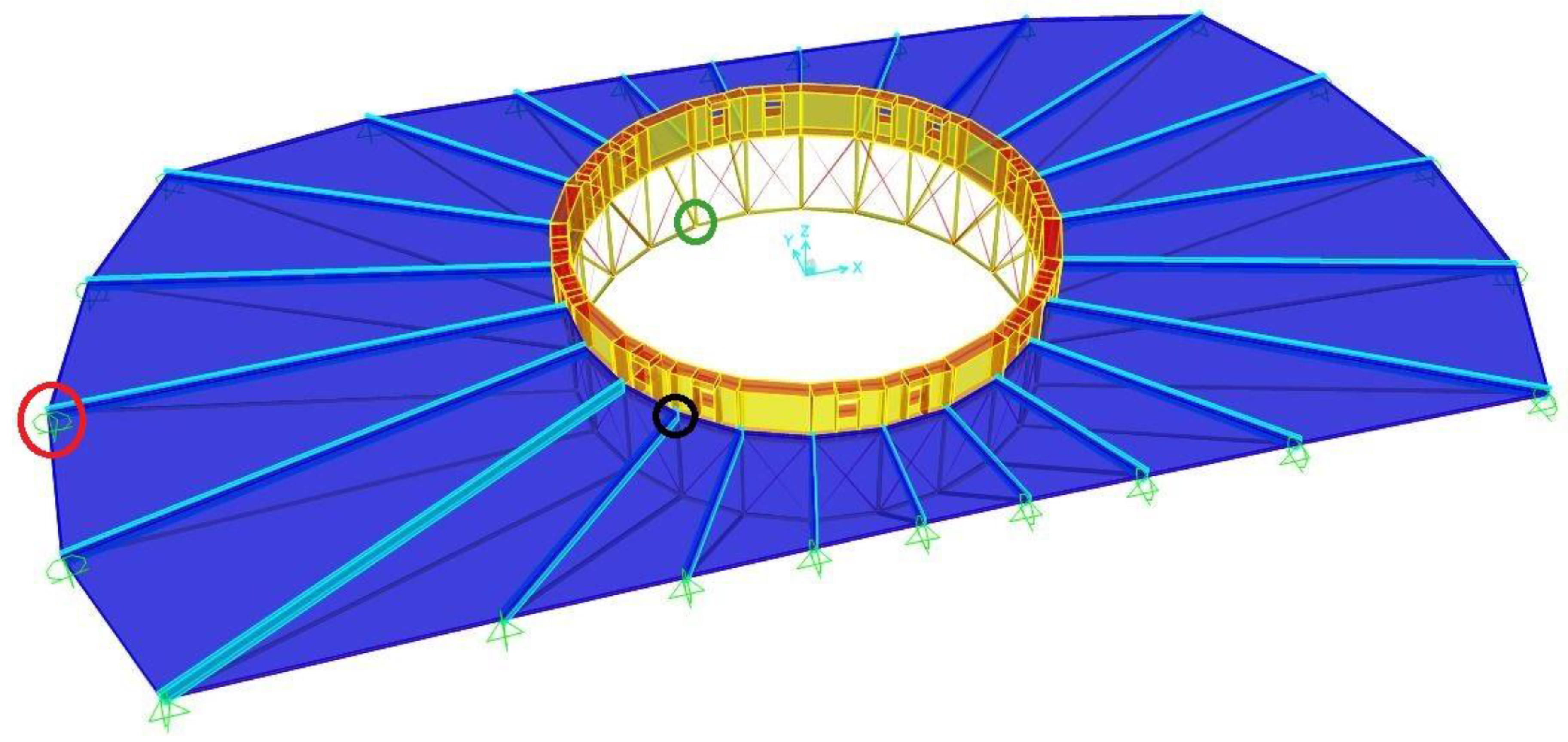
Figure 2.
Connection between the floor and the top beams of the radial trusses (dimensions are in cm).
Figure 2.
Connection between the floor and the top beams of the radial trusses (dimensions are in cm).
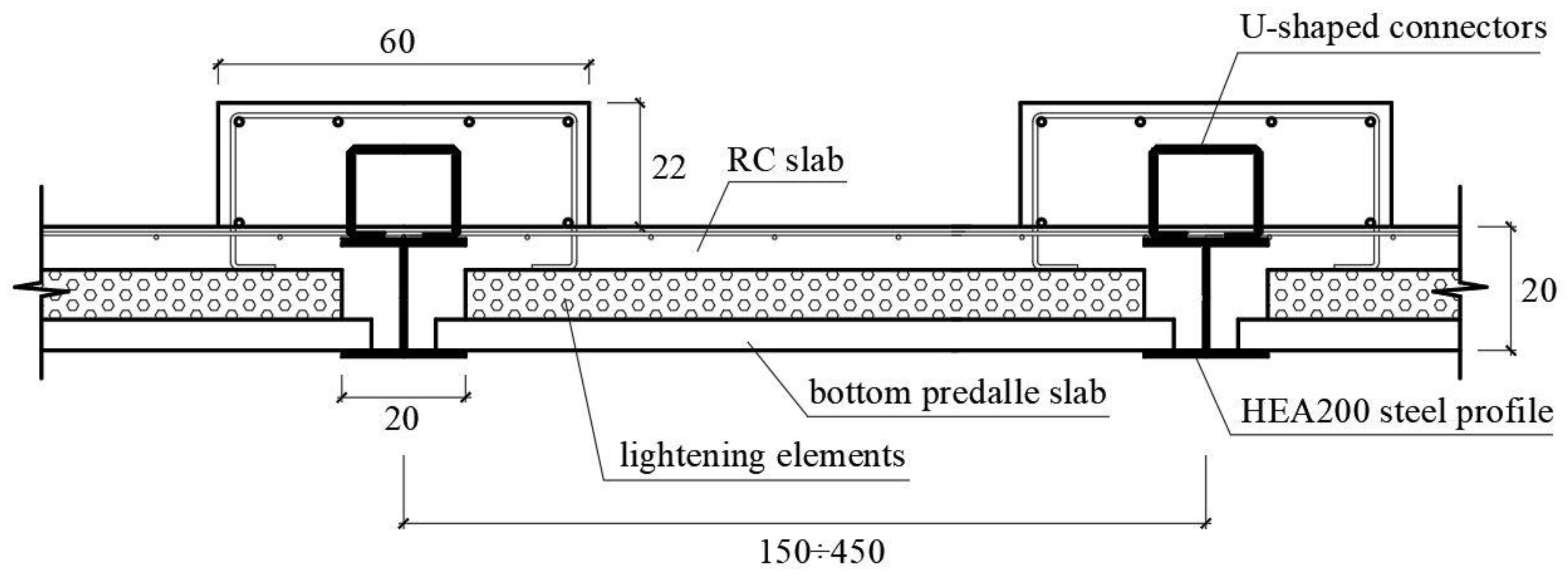
Figure 3.
Diagonal ties connecting the nodes of adjacent radial trusses.
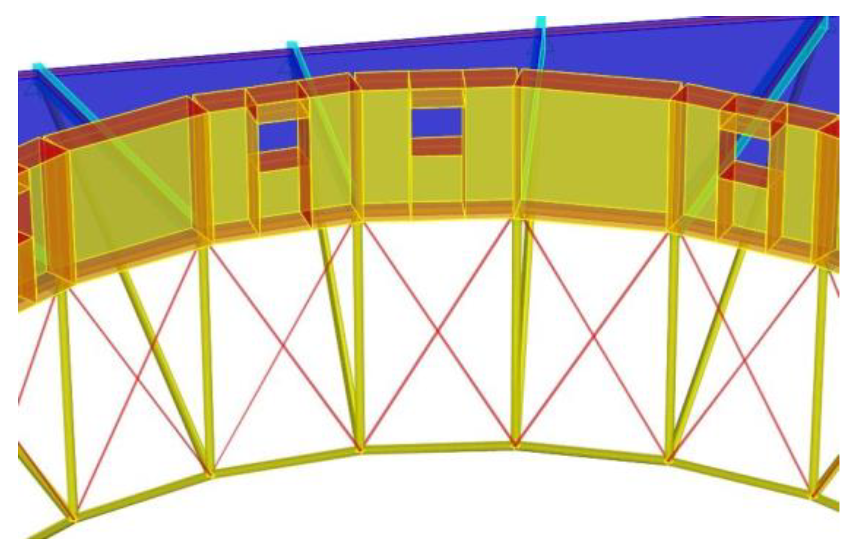
Figure 4.
Space between adjacent bottom predalles slabs.
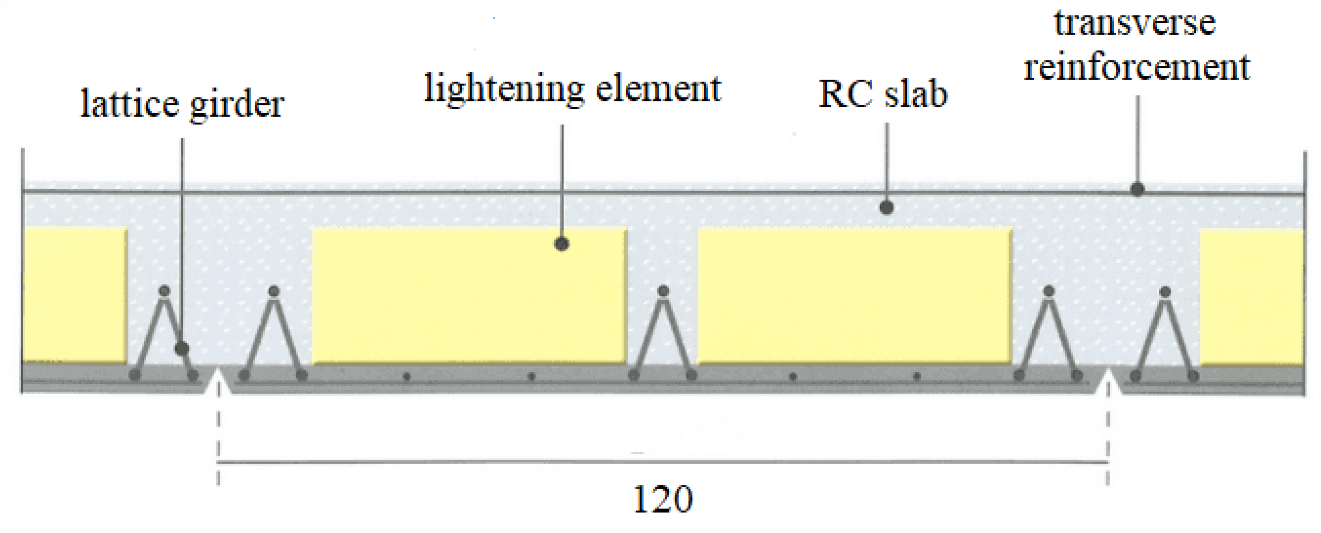
Figure 5.
Schematic representation of a floor in the building FE model.
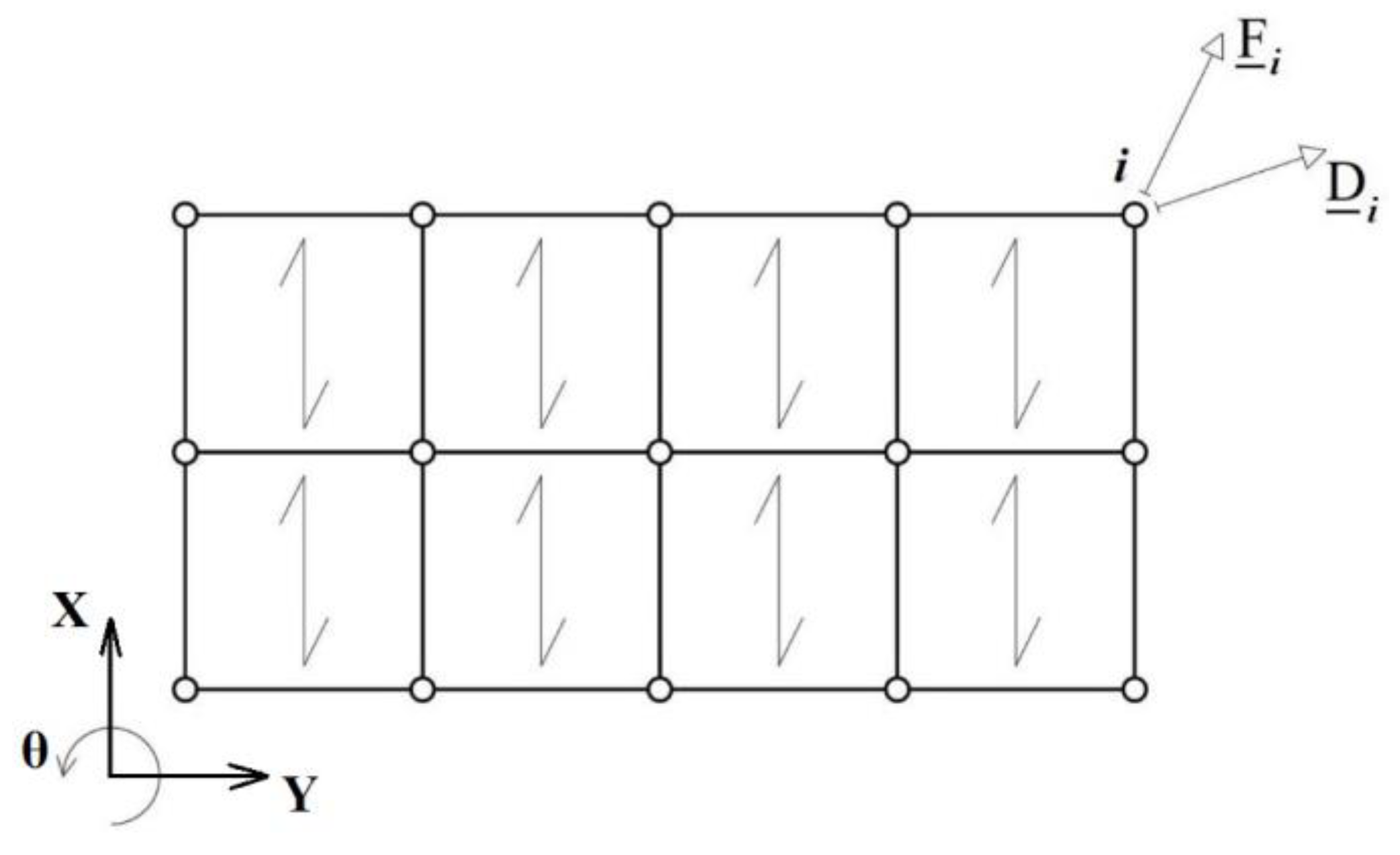
Figure 6.
Discretization of floor cells and contouring beams through FE with smaller dimensions.
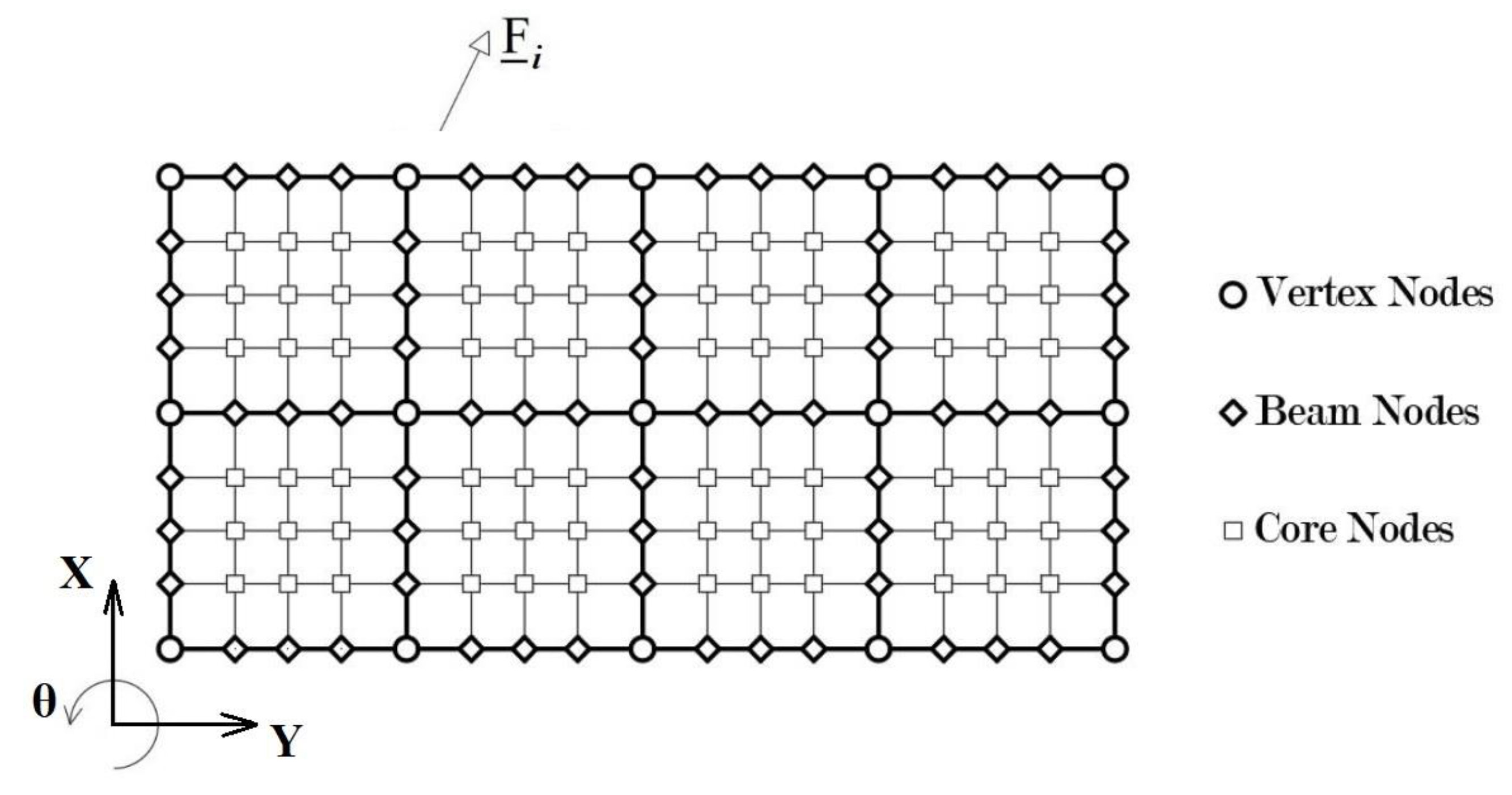
Figure 7.
Floor cell.
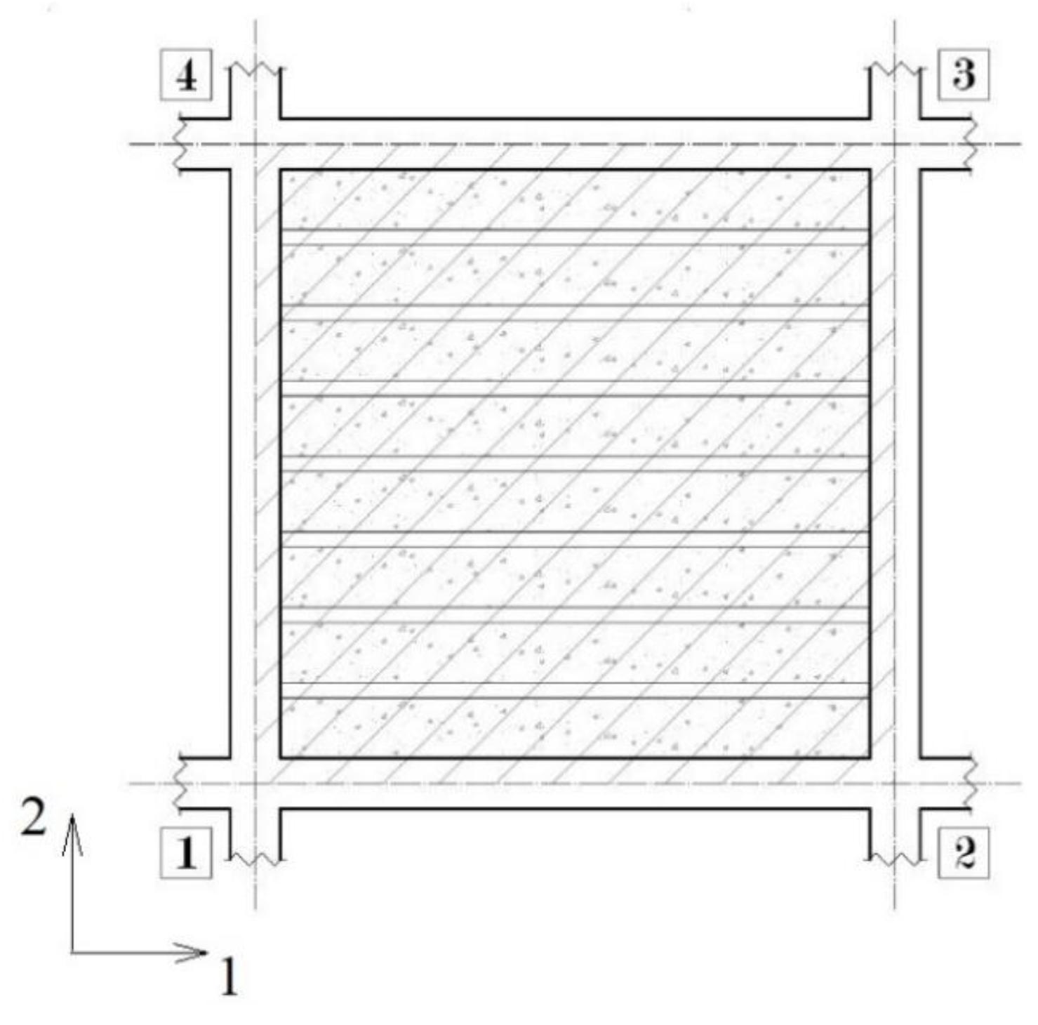
Figure 8.
Floor cell FE model.
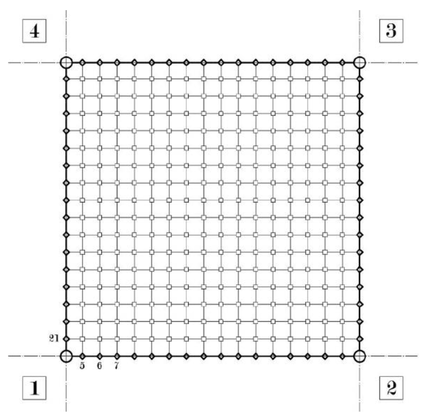
Figure 9.
Deformation patterns.
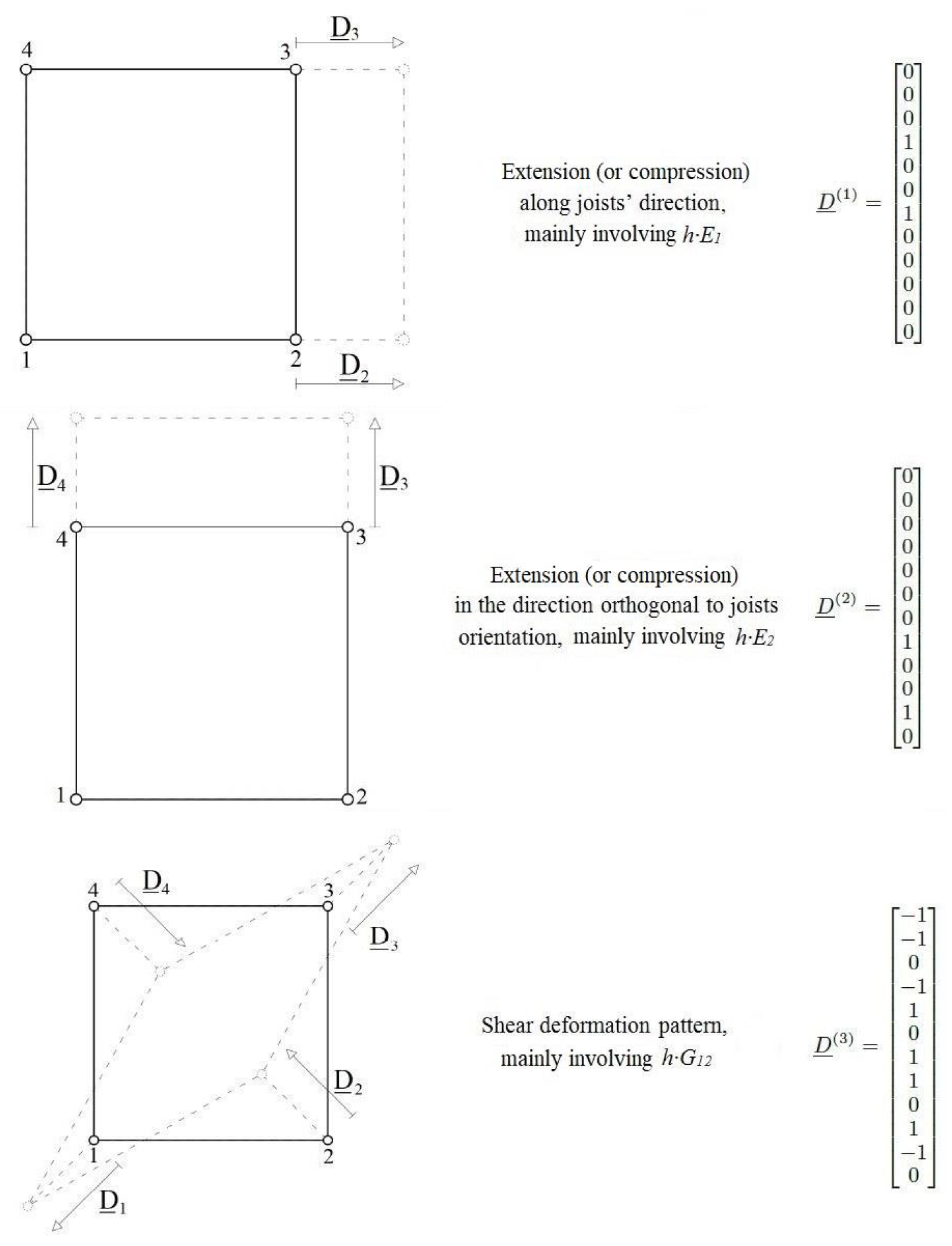
Figure 10.
Static schemes of (a) MODE 1, (b) MODE 2 (c) and MODE 3.
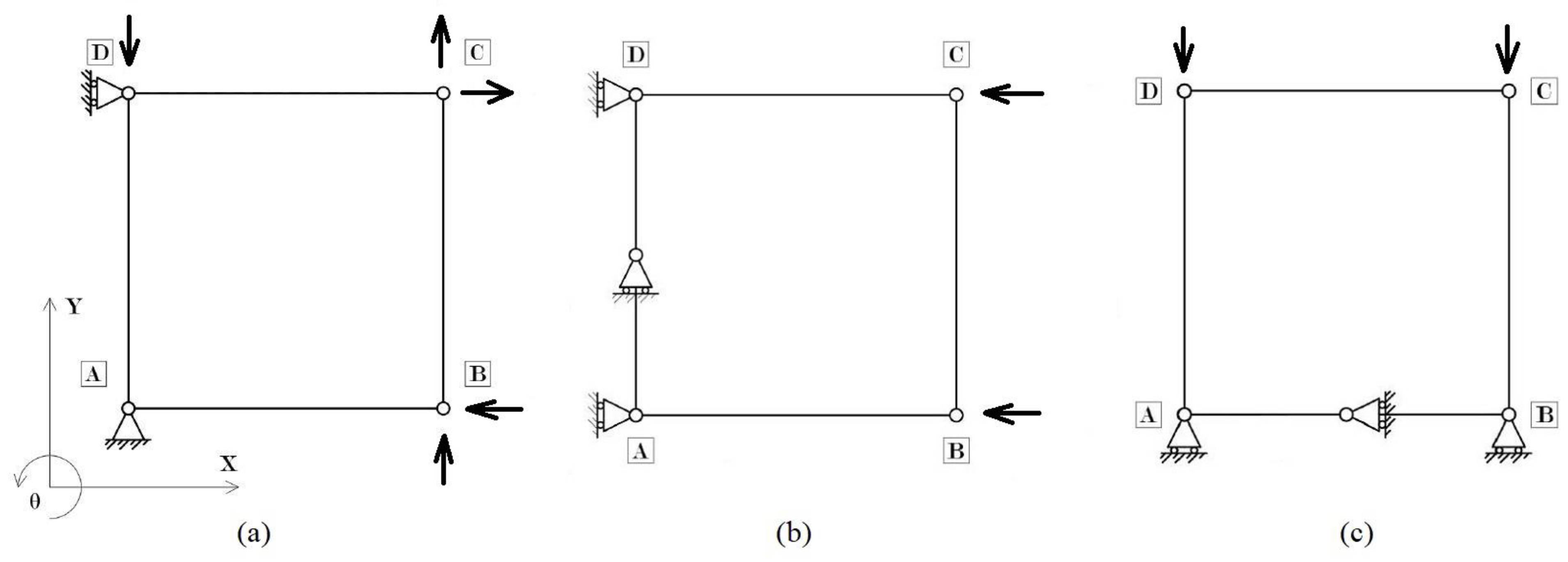
Figure 11.
Parallelepiped constituting the intersection between two adjacent beams in the floor cell model made by solid finite elements.
Figure 11.
Parallelepiped constituting the intersection between two adjacent beams in the floor cell model made by solid finite elements.
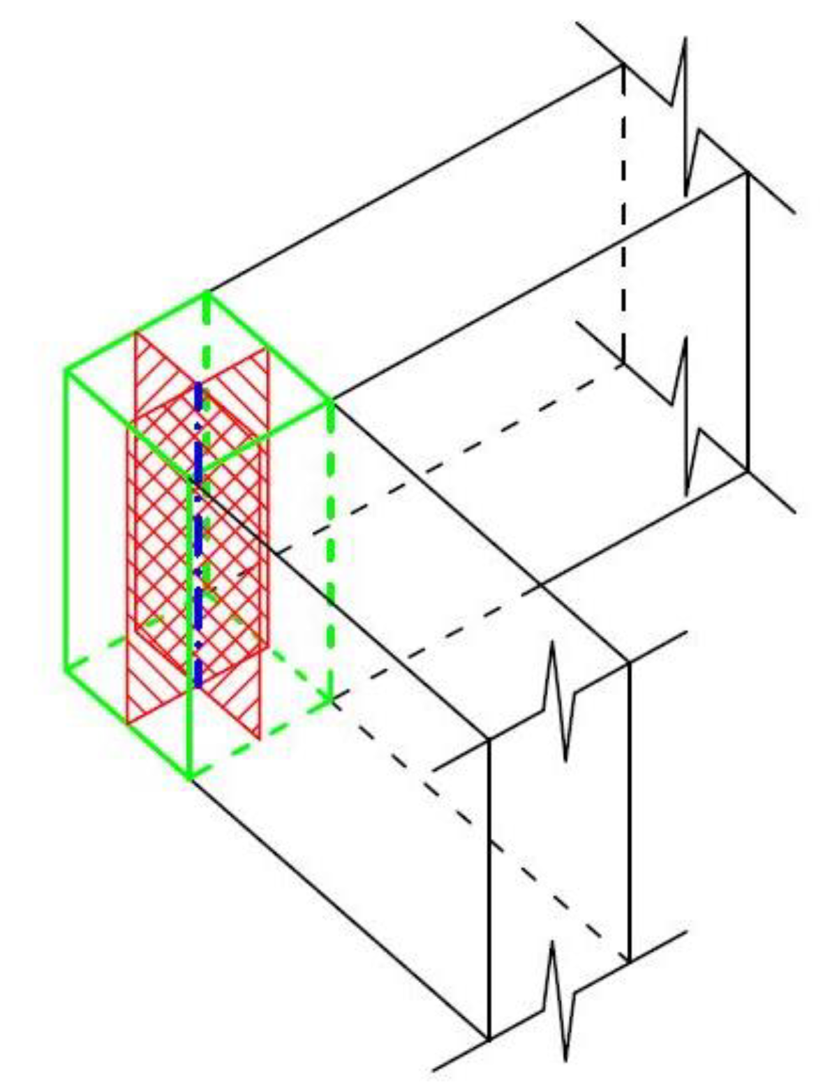
Figure 12.
Mesh nodes in a vertical cross-section of the parallelepiped, to which loads and restraints are applied at intersection regions.
Figure 12.
Mesh nodes in a vertical cross-section of the parallelepiped, to which loads and restraints are applied at intersection regions.
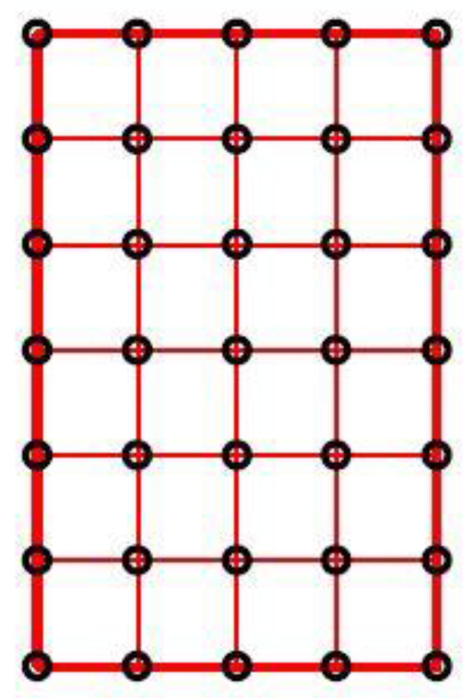
Figure 13.
Most used floor typology in the set of Italian existing RC schools considered in the survey.
Figure 13.
Most used floor typology in the set of Italian existing RC schools considered in the survey.
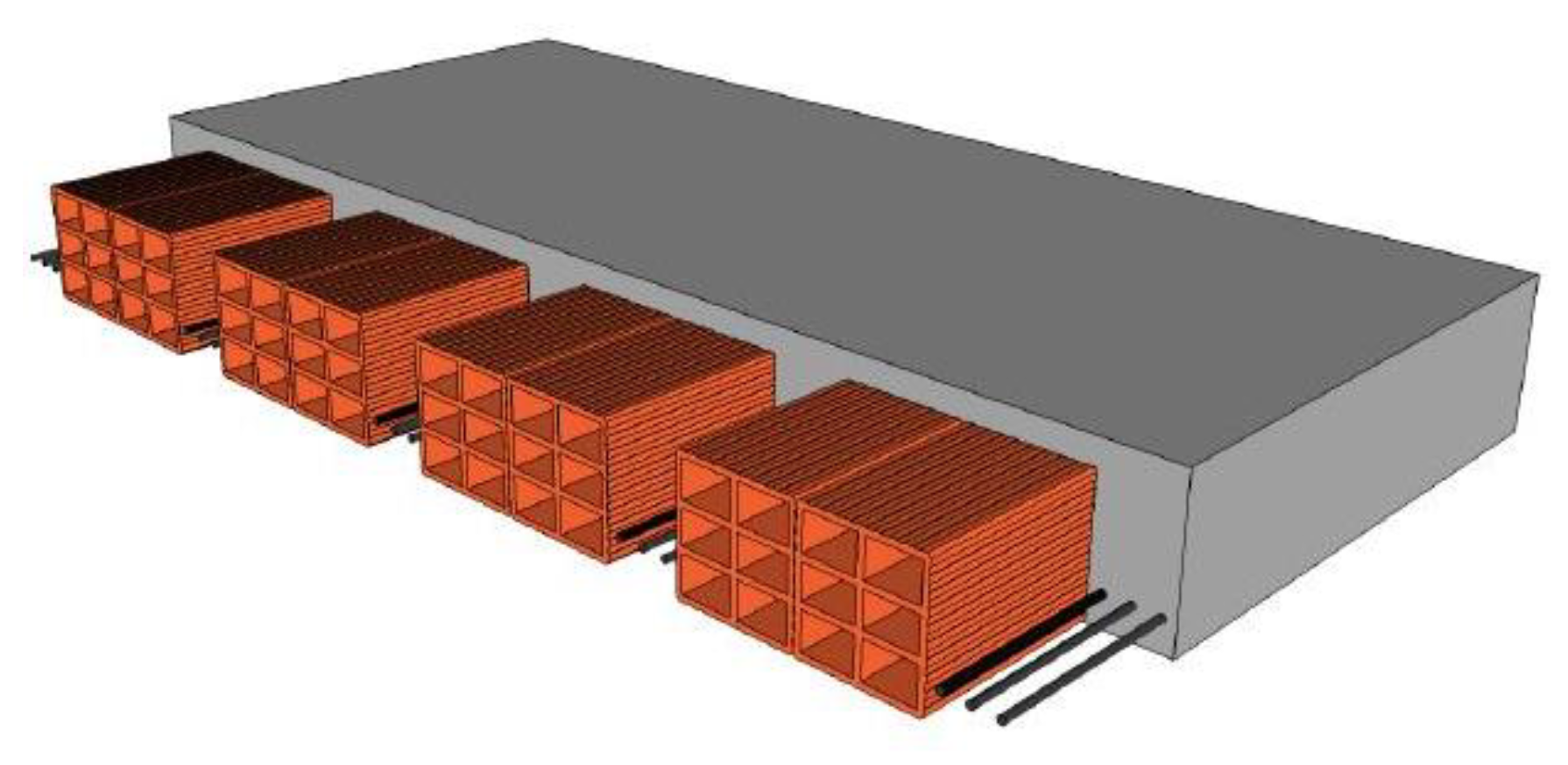

Table 1.
Elastic properties of the homogenized orthotropic material constituting the equivalent solid bricks used in the 3D model to reproduce the real hollow ceiling bricks.
Table 1.
Elastic properties of the homogenized orthotropic material constituting the equivalent solid bricks used in the 3D model to reproduce the real hollow ceiling bricks.
|
E1 (MPa) |
E2 (MPa) |
G12 (MPa) |
ν12 |
ν21 |
|---|---|---|---|---|
| 6,970 | 4,000 | 0.1 | 0.2 | 0.115 |
Table 2.
Elastic properties of the homogenized orthotropic material of the equivalent 2D elements obtained for the considered case study.
Table 2.
Elastic properties of the homogenized orthotropic material of the equivalent 2D elements obtained for the considered case study.
|
Ex (MPa) |
Ey (MPa) |
Gxy (MPa) |
νxy |
νyx |
|---|---|---|---|---|
| 45,200 | 35,300 | 14,500 | 0.2 | 0.26 |
Disclaimer/Publisher’s Note: The statements, opinions and data contained in all publications are solely those of the individual author(s) and contributor(s) and not of MDPI and/or the editor(s). MDPI and/or the editor(s) disclaim responsibility for any injury to people or property resulting from any ideas, methods, instructions or products referred to in the content. |
© 2024 by the authors. Licensee MDPI, Basel, Switzerland. This article is an open access article distributed under the terms and conditions of the Creative Commons Attribution (CC BY) license (https://creativecommons.org/licenses/by/4.0/).
Copyright: This open access article is published under a Creative Commons CC BY 4.0 license, which permit the free download, distribution, and reuse, provided that the author and preprint are cited in any reuse.


