Submitted:
08 May 2023
Posted:
09 May 2023
You are already at the latest version
Abstract
Considering rotation-induced centrifugal stiffening, spin softening, and Coriolis effects, the three-dimensional finite element model of a rotating blade with a dovetail structure is built through the contact dynamics theory. The fixed-interface component mode synthesis method is then adopted to reduce the model for high computational efficiency and adequate model accuracy. The effects of the number of normal modes on the first-six-order modal characteristics of the model varying with the rotating speed are studied between the reduced and full models. Next, the influence of rotating speed and friction factor on the nonlinear dynamic characteristics of the model under the action of aerodynamic force are elaborately discussed. The results show that: (1) tenon-mortise joint contact-induced nonlinearity under low rotating speeds results in the intermittent interference of contact surfaces and frequency multiplications of aerodynamic excitation frequency in the spectrum cascades, while that under high rotating speeds causes the continuous interface contact and asynchronous excitation at the tenon-mortise joint; (2) the increase of friction factor results in a lower contact pressure distribution and the right shift of the resonance peak (i.e., hard nonlinearity).
Keywords:
rotating blade with a dovetail structure
; fixed-interface component mode synthesis method
; aerodynamic force
; interface contact
; dynamic characteristics
1. Introduction
The blisks with mortise-tenon joints are widely used in modern aero-engines such as the fan, the compressor, and the turbine for the purpose of vibration attenuation, maintenance, and cost reduction. With the development of the modern aviation industry, key performance indicators such as high thrust-to-weight ratio, low fuel consumption, and high reliability are increasingly popular with aeronautical engineers thus resulting in a much harsher working environment such as high-speed, high-temperature, and high load for the rotating blisk. This can easily aggravate the severe stress concentration located at the tenon joint thus causing the blisk failure. Therefore, it is rather important to figure out their dynamic behaviors for engineering design and fault diagnosis purposes.
Numerous literature on the dynamic characteristics of the blisk with mortise-tenon joints has been published. Ma et al. [1] utilized the un-reduced three-dimensional finite element model of a single blisk sector with the tenon-mortise joint structure to study the effects of rotating speeds and penetration depths on the corresponding rubbing characteristics. Quaegebeur et al. [2] adopted the component nonlinear complex mode synthesis method integrated with the dynamic Lagrangian frequency time algorithm to analyze the effects of friction factor, rotating speed, and traveling/standing wave excitation on the amplitude-frequency responses of an industrial blisk with the tenon-mortise joint structure. Li et al. [3] used the plane beam elements to simulate the in-plane flapwise vibration of a mock blade with a dovetail structure and analyzed the effects of rotating speed, friction factor, and excitation level on the amplitude-frequency curves and hysteretic characteristics of the system. In their later works [4], the incremental harmonic balance method combined with a linearization method of friction was adopted to analyze the nonlinear dynamics of the model in Ref. [3]. Considering the bending-bending-axial coupling vibration of a pre-twisted blade, She et al. [5] expanded the single blisk sector in Refs. [3,4] to the whole blisk, and investigated the corresponding eigenvalues of veering and merging phenomena. Shangguan B et al. [6] investigated the dynamic responses of a compressor blade with dovetail attachment under different rotating speeds from an experimental point of view, and the experimental results showed the existence of an optimal centrifugal force causing the minimal resonant amplitude and best damping effect. In their later works [7], a fractal contact friction model was introduced to describe the friction force situated at the tenon-mortise contact surfaces, and the multi-harmonic balance method combined with Newton iterative algorithm was used to analyze the nonlinear vibration responses of a loosely assembled blade with dovetail root. Using the one-way coupled and harmonic balance methods, Lassalle and Firrone [8] investigated the limit cycle oscillations of a blisk with dovetail structure caused by flutter and friction. Zucca et al. [9] developed a refined version of the state-of-the-art contact model to simulate the microslip between the blade and the disk contact surfaces and evaluated their effects on the forced responses of a blisk. Appaji et al. [10] investigated the stress state at the contact interface of a dovetail blisk attachment for varying friction factors and rotating speeds, and the results showed that the peak stress decreased with the increasing friction factor. Chen et al. [11] built the two- and three-dimensional finite element models of both simplified and realistic blade-root structures and discussed the effects of contact interface parameters, contact interface geometry, and various loading conditions on the hysteresis characteristics. In their later works [12], the high-fidelity calculation of modal damping at root joints for a lone blade as well as for a tuned blisk was performed. Using the lumped-parameter model with dry friction nonlinearity between the blade root and the disk to simulate the fundamental sector of a blisk, Joannin et al. [13] studied the forced responses and nonlinear complex modes for a tuned system under different excitation levels and for a mistuned system under random stiffness mistuning and different excitation levels. Schwarz et al. [14] carried out the nonlinear experimental modal analysis, which verified the phase-resonant method to isolate nonlinear modes in accordance with the extended periodic motion concept and the extracted nonlinear modal frequency and damping ratio in good agreement with the near-resonant frequency response tests. Based on the lumping parameter model of a single blisk sector subjected to dry damping under harmonic excitation, Liu et al. [15] used a multi-harmonic method combined with a continuation procedure to investigate the effects of excitation level, tangential stiffness of friction model, and normal contact force on the steady vibration responses of the system. For the purpose of prediction of the residual life, Canale et al. [16] adopted the commercial software FRANC3D to analyze the low cycle fatigue crack propagation of a rotating blade with a dovetail structure, and the results showed 45° with respect to 30° and 60° flank angles and a lower friction factor resulting in a lower crack propagation rate. Yuan et al. [17] investigated a novel adaptive reduced order modeling method to reduce the high-fidelity fan blisk with dovetail joints and then analyzed the nonlinear modal characteristics under different friction factors and pre-loadings. Anandavel et al. [18] performed an analysis of the effects of preloading at the dovetail interface on the contact tractions, slip levels, and contact stress distribution for a single blisk sector, and the results indicated that the preloading effect was beneficial to reducing the peak contact pressure and stress difference between top and bottom contact edges. Fernandes et al. [19] investigated the change rules of stress intensity factors KI, KII, and KIII varying with crack width for both a single blade and a blisk using commercial software ANSYS and FRANC3D, and analyzed the corresponding natural frequency changing with crack size and rotating speed. Wei et al. [20] used the finite element method to study the variation of the contact state in a dovetail attachment and pointed out the movement of the contact edge dominated by the relative slip and compaction of the tenon-mortise joint.
From the literature listed above, it can be concluded that most research focused on the analysis of the contact properties, hysteresis behavior located at the contact region, and modal characteristics of a single blisk sector with a dovetail structure, however, less attention is paid to the nonlinear vibration features caused by the tenon-mortise joint, which can be rather helpful to realize the on-line monitoring and fault diagnosis. In addition, a macroslip model to describe the contact behaviors between the tenon and the mortise is relatively inaccurate especially when quantitatively analyzing the dynamic characteristics of the rotating blisk with a dovetail structure. In order to make up for the existing deficiencies, a single blisk sector with a dovetail structure is taken as an example, whose three-dimensional finite element model is built via the solid and contact elements. Then the fixed-interface component mode synthesis method is adopted to establish the reduced blisk sector model, and the corresponding availability is verified via the frequency convergence and vibration mode analysis. Next, the effects of rotating speed and friction factor on the nonlinear dynamic characteristics of the reduced model under the action of aerodynamic force are elaborately discussed. Finally, some conclusions are made.
2. Finite element model
The three-dimensional finite element model of a rotating blade with a dovetail structure discretized by eight-node solid elements is shown in Figure 1(a). Material properties of the model are set as follows: Young’s modulus E=125 GPa, Poission’s ratio ν=0.3, and density ρ=4370 kg/m3. Given that only one cyclic sector corresponding to a single blade (1/38 blisk) is included, the symmetric constraints applied to the sector interfaces I and II are considered in the cylindrical coordinate system OXYZ (see Figure 1(a)). Ignoring the relative motions between the disk and the shaft, the fixed constraints are applied to the inner hole of the disk sector (see Figure 1(a)). Here, the contact behaviors located at contact pairs 1 and 2 are simulated via the standard unilateral contact with the penalty function method, and the contact surfaces located at the blade and the disk are set as Conta173 and Targe170, respectively (see Figure 1(b)). The effects of both the aerodynamic force P=P0⋅sin(2πfet) acting on the pressure surface and the gravity acting on the whole model are included (see Figure 1(a)). Here, P0, fe, and t represent the aerodynamic amplitude, excitation frequency, and time, respectively.
In light of large numbers of degrees of freedom and contact pairs in the model, the fixed-interface component mode synthesis method is then utilized to reduce the model for higher computation under the premise of ensuring accuracy. Here, the tip nodes 1, …, 4 (see Figure 1(a)) and nodes located at the contact pairs 1, 2 (see Figure 1(b)) are defined as master nodes, and the number of normal modes is labeled with js. The reduced model simulated by Matrix50, Conta173, and Targe170 is shown in Figure 1(b). si, j in Figure 1(b) represents the jth node at the ith section of the contact surface, and it can be also seen from Figure 1(b) that 16 sections and 29 nodes per section in total are divided.
3. Dynamic characteristic analysis
This section will discuss the influences of js, rotating speed n, and friction factor μ on the dynamic characteristics of the model. Corresponding simulation parameters are listed in Table 1.
3.1. Modal characteristics
(1) Case 1: effects of the number of normal modes js
Effects of js on the first-six-order natural frequencies are shown in Figure 2. It can be seen from Figure 2(a) that with the increasing js, all the first-six-order natural frequencies are gradually convergent. Especially when js≥9, the natural frequencies are almost unchanged. Taking the results of the full model under n=4000 rev/min as a benchmark, the frequency error varying with n is shown in Figure 2(b). The results indicate that the maximum error for the first-six-order natural frequencies is no more than 1% when js≥9. Based on this, js=10 is then adopted in the following study.
(2) Case 2: effects of the rotating speed n
The first-six-order natural frequencies obtained from the full and reduced models varying with n are shown in Figure 3(a). It can be seen from the figure that the natural frequencies of each order increase with the increase of n. Corresponding modal shapes under n=4000 rev/min are plotted in Figure 3(b). As a whole, both the dynamic frequencies and modal shapes obtained from both models show a good agreement with each other. However, it takes about 80 s for the reduced model and 120 s for the full model. This strongly shows that the reduced model has good precision and low computational cost. In this paper, the tenfold rotating frequency is taken as fe in the aerodynamic force thus resulting in the four possible resonance points within n∈[1000, 20000] rev/min, i.e., A(4000 rev/min, 649.4 Hz), B(11000 rev/min, 1867.8 Hz), C(12000 rev/min, 2064.5 Hz), and D(15000 rev/min, 2454.3 Hz) (see Figure 3(a)).
3.2. Nonlinear vibration characteristics
(1) Case 3: effects of the rotating speed n
The Y-spectrum of tip node 1 (see Figure 1(a)) extracted from the last 25 rotation periods (i.e. 25×60/n s) is plotted in Figure 4(a), and corresponding simulation parameter settings can refer to Table 1. Besides fe in Figure 4(a), there exist multiple frequency components (i.e. 2fe, 3fe, 4fe,…) when n∈[1000, 5000] rev/min, and this indicates that the model is of strong nonlinearity under the action of aerodynamic force. With increasing n, the high multiple frequency components disappear when n∈[0, 4000] rev/min, and this indicates that the nonlinearity of the model is weakened and even disappeared. In Figure 4(b), the amplitude Y at fe varying with n is depicted. The figure shows that the resonance point is E(4000 rev/min, 12.6 mm), and this is in accordance with the results shown in Figure 3(a). A particularly interesting phenomenon is that there exists a frequency component k⋅fe. Here, both fe and k varying with n are plotted in Figure 4(c) and 4(d), respectively. It can be seen from the figures that the variation of fe has good agreement with those obtained from the fit function 10×n/60, i.e. fe is the actual aerodynamic frequency, while k in Figure 4(d) varies with n.
In order to further clarify the above issues, some in-depth analyses are made. In terms of the nonlinearity phenomenon presented Figure 4(a), the corresponding explanations are made below: the centrifugal force under low rotating speeds is relatively small thus leading to intermittent contacts between the mortise and the tenon than that under high rotating speeds, which directly causes the impulse and continuous contact force distributions located at the tenon joint interfaces under the action of the aerodynamic force, respectively (see Figure 5(a) and Figure 6(a)). The vibration responses of the contact pressure for contact pair 1 (see Figure 1(a)) under n=4000 rev/min and 19,000 rev/min are taken as examples (see Figure 5 and Figure 6), respectively. In Figure 5(a), the contact pressure is of obvious impulse characteristics thus leading to a strong broadband excitation, and the corresponding spectrum cascade in Figure 5(b) also illustrates it. Here, it is worth noting that the node order in Figure 5 can refer to Figure 1(b). The spectrum cascades related to Figure 5(a) are shown in Figure 5(c). Besides fe, there exist high multiple frequencies such as 2fe, 3fe, 4fe, …, and constant frequency 0fe, and this is in accordance with spectrum distribution in Figure 4(a). In addition, both the frequency and amplitude at fe varying with n are extracted, as shown in Figure 5(c). The figure shows that fe at all the contact nodes are in good agreement with 10×n/60, and the maximum contact pressure is no more than 600 MPa.
The contact pressure distribution under n=19000 rev/min is shown in Figure 6. In Figure 6(a), the contact pressure is of obvious continuous harmonics with a non-zero mean value. This indicates that the mortise and the tenon are always in contact with each other, thus weakening the nonlinearity of the model. The spectrum cascades in Figure 6(b) shows that the amplitude at 0fe caused by high centrifugal force is much larger than that at other frequency, and this also indicates that the close contact between interfaces will weaken the nonlinearity of the rotating blade with a dovetail structure. In addition, fe at all the nodes in region A is always stable at 10×n/60, which indicates a frequency-locking phenomenon. However, the frequency at all the nodes in region B is fluctuant (see Figure 6(c)), which indicates a asynchronous excitation. The phenomenon strongly illustrates that single rather than distributed contact is actually inaccurate to simulate the interactions between the mortise and the tenon.
(2) Case 4: effects of the friction factorμ
Effects of μ on the Y-vibration responses of tip node 1 are shown in Figure 7. In Figure 7(a), besides 0fe, it is mainly reflected in the frequency multiplication of fe (i.e. 2fe, 3fe, 4fe, …). It seems that the increasing μ (μ∈[0.1, 0.5]) has little impact on the spectrum distribution (see Figure 7(a)). The amplitude-frequency responses are shown in Figure 7(b). Compared with Figure 4(b), it can be concluded that the increasing μ results in the right shift of the resonance point (i.e., E(0.3, 12.6 mm)→F(0.44, 13.4 mm)) thus showing a hard nonlinearity.
The vibration responses of contact pressure for contact pair 1 under μ=0.1, 0.3, and 0.44 are shown in Figure 8, Figure 5, and Figure 9, respectively. It can be seen from the figures that with the increasing μ, the amplitude of contact pressure are decreasing. In addition, the frequency components of contact pressure consist of 0fe, 1fe, 2fe, 3fe, 4fe,…, and fe is of the good frequency-locking feature.
4. Conclusions
In this paper, the three-dimensional finite element model of a rotating blade with a dovetail structure is established via the contact dynamics theory. In order to improve computational efficiency, the fixed-interface component mode synthesis method is used to reduce the model under the premise of assuring the model’s accuracy. Then the effects of rotating speed and friction factor on the dynamic characteristics of the model are studied. Some conclusions can be summarized as follows:
(1) Under low rotating speeds, the intermittent contact between interfaces results in frequency multiplications in the spectrum cascades; under high rotating speeds, the distributed interference within contact regions results in asynchronous excitation thus leading to a complicated frequency distribution in the spectrum cascades.
(2) The larger the friction factor is, the lower the interface contact pressure is. In addition, the increasing friction factor results in a higher resonance frequency, which indicates a hard nonlinearity of the model.
Acknowledgments
This project is financially supported by the National Natural Science Foundation (Grant nos. 12202368, 12172307, 12172311), the Natural Science Foundation of Sichuan Province (Grant nos. 22NSFSC0576, 22NSFSC0666, 2023NSFSC0068), the Opening Project of Applied Mechanics and Structure Safety Key Laboratory of Sichuan Province (No. SZZZKT-202206), the Key Laboratory of Vibration and Control of Aero-Propulsion System, Ministry of Education, Northeastern University of China (No. VCAME202205, VCAME202103), and the Fundamental Research Funds for the Central Universities (Grant nos. 2682021CX081, 2682021ZTPY036).
References
- Ma H, Wang D, Tai X Y, Wen B C. Vibration response analysis of blade-disk dovetail structure under blade tip rubbing condition[J]. Journal of Vibration and Control. 2017, 23(2): 252-271. [CrossRef]
- Quaegebeur S, Chouvion B, Thouverez F. Nonlinear dynamic analysis of three-dimensional bladed-disks with frictional contact interfaces based on cyclic reduction strategies[J]. International Journal of Solids and Structures. 2022, 236-237: 111277. [CrossRef]
- Li C F, Shen Z C, Zhong B F, Wen B C. Study on the nonlinear characteristics of a rotating flexible blade with dovetail interface feature[J]. Shock and Vibration. 2018, Volume 2018, Article ID 4923898, 13 pages. [CrossRef]
- Li C F, Liu X W, Tang Q S, Chen Z L. Modeling and nonlinear dynamics analysis of a rotating beam with dry friction support boundary conditions[J]. Journal of Sound and Vibration. 2021, 498: 115978. [CrossRef]
- She H X, Li C F, Tang Q S, Wen B C. Veering and merging analysis of nonlinear resonance frequencies of an assembly bladed disk system[J]. Journal of Sound and Vibration. 2021, 493: 115818. [CrossRef]
- Shangguan B, Xu Z. Experimental study of friction damping of blade with loosely assembled dovetail attachment[J]. Proceedings of the Institution of Mechanical Engineers Part A-Journal of Power and Energy. 2012, 226(6):738-750. [CrossRef]
- Shangguan B, Yu F L, Duan J Y, Gao S, Xiao J F. A fractal contact friction model and nonlinear vibration response studies of loosely assembled blade with dovetail root[C]. Proceedings of the ASME Turbo Expo 2016: Turbomachinery Technical Conference and Exposition, 2016.
- Lassalle M, Firrone C M. A parametric study of limit cycle oscillation of a bladed disk caused by flutter and friction at the blade root joints[J]. Journal of Fluids and Structures. 2018, 76: 349-366. [CrossRef]
- Zucca S, Firrone C M, Gola M M. Numerical assessment of friction damping at turbine blade root joints by simultaneous calculation of the static and dynamic contact loads[J]. Nonlinear Dynamics. 2012, 67(3): 1934-1955. [CrossRef]
- Appaji Gowda B M, Yeshovanth H R, Siddaraju C. Investigation and efficient modeling of an dovetail attachment in aero-engine[J]. Procedia Materials Science. 2014, 5: 1873-1879. [CrossRef]
- Chen J J, Zang C P, Zhou B, Petrov E P. A study of friction microslip modeling for dynamic analysis of bladed discs with root joints[J]. Journal of Mechanical Engineering Science. 2018, 233(8): 2599-2641. [CrossRef]
- Chen J J, Zang C P, Zhou B, Petrov EP. High-fidelity calculation of modal damping caused by friction at blade roots for single blades and tuned bladed disc assemblies[J]. Proceedings of the Institution of Mechanical Engineers, Part C: Journal of Mechanical Engineering Science. 2021, 235(15): 2810-2831. [CrossRef]
- Joannin C, Chouvion B, Thouverze F, Mbaye M, Ousty J P. Nonlinear modal analysis of mistuned periodic structures subjected to dry friction[J]. Journal of Engineering for Gas Turbines and Power. 2016, 138(7): 072504. [CrossRef]
- Schwarz S, Kohlmann L, Hartung A, Gross J, Scheel M, Krack M. Validation of a turbine blade component test with frictional contacts by phase-locked-loop and force-controlled measurements[J]. Journal of Engineering for Gas Turbines and Power. 2020, 142(5): 051006. [CrossRef]
- Liu T Y, Zhang D, Xie Y H. A nonlinear vibration analysis of forced response for a bladed-disk with dry friction dampers[J]. Journal of Low Frequency Noise, Vibration and Active Control. 2019, 38(3-4): 1522-1539. [CrossRef]
- Canale G, Kinawy M, Maligno A, Sathujoda P, Citarella R. Study of mixed-mode cracking of dovetail root of an aero-engine blade like structure[J]. Applied Sciences. 2019, 9(18): 3825. [CrossRef]
- Yuan J, Schwingshackl C, Salles L, Wong C, Patsias S. Reduced order method based on an adaptive formulation and its application to fan blade system with dovetail joints[C]. Proceedings of the ASME Turbo Expo 2020: Turbomachinery Technical Conference and Exposition, 2020.
- Anandavel K, Prakash R V, Davis A. Effect of preloading on the contact stress distribution of a dovetail interface[J]. World Academy of Science, Engineering and Technology. 2010, 4(10):1107-1112. [CrossRef]
- Fernandes R, El-Borgi S, Ahmed K, Friswell M I, Jamia N. Static fracture and modal analysis simulation of a gas turbine compressor blade and bladed disk system[J]. Advanced Modeling and Simulation in Engineering Sciences. 2016, 3, Article number 30, 23 pages. [CrossRef]
- Wei D S, Ma M D, Zhang H, Hu C, Wang Y R. Study of the variation of contact state near the contact boundary in a dovetail attachment under different loads[J]. Engineering Failure Analysis. 2019, 105: 518-526. [CrossRef]
Figure 1.
Schematic of a rotating blade with a dovetail structure: (a) full model, (b) reduced model.
Figure 1.
Schematic of a rotating blade with a dovetail structure: (a) full model, (b) reduced model.
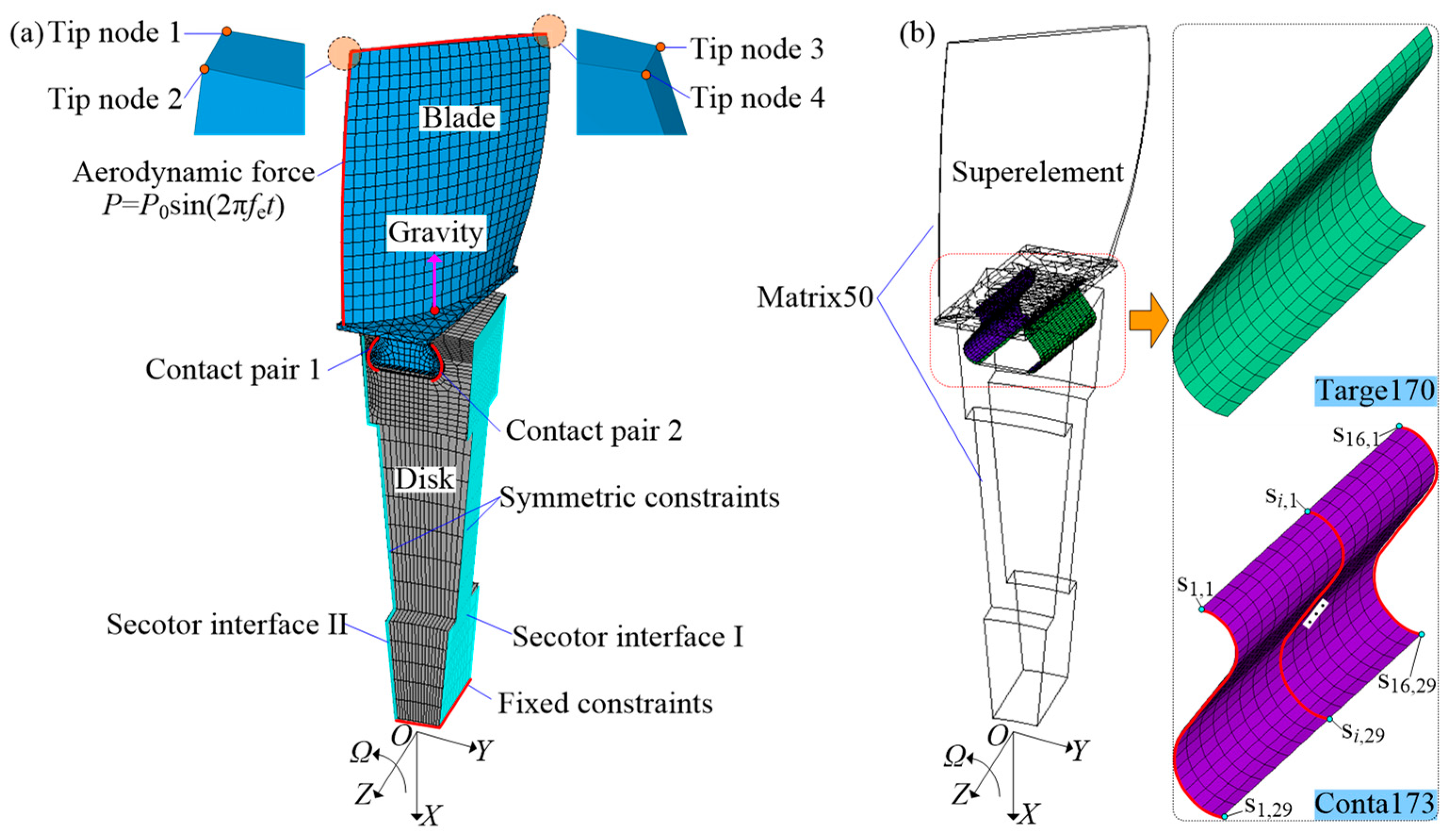
Figure 2.
Effects of js on the first six-order frequencies under n=4000 r/min: (a) frequency convergency, (b) error curve.
Figure 2.
Effects of js on the first six-order frequencies under n=4000 r/min: (a) frequency convergency, (b) error curve.
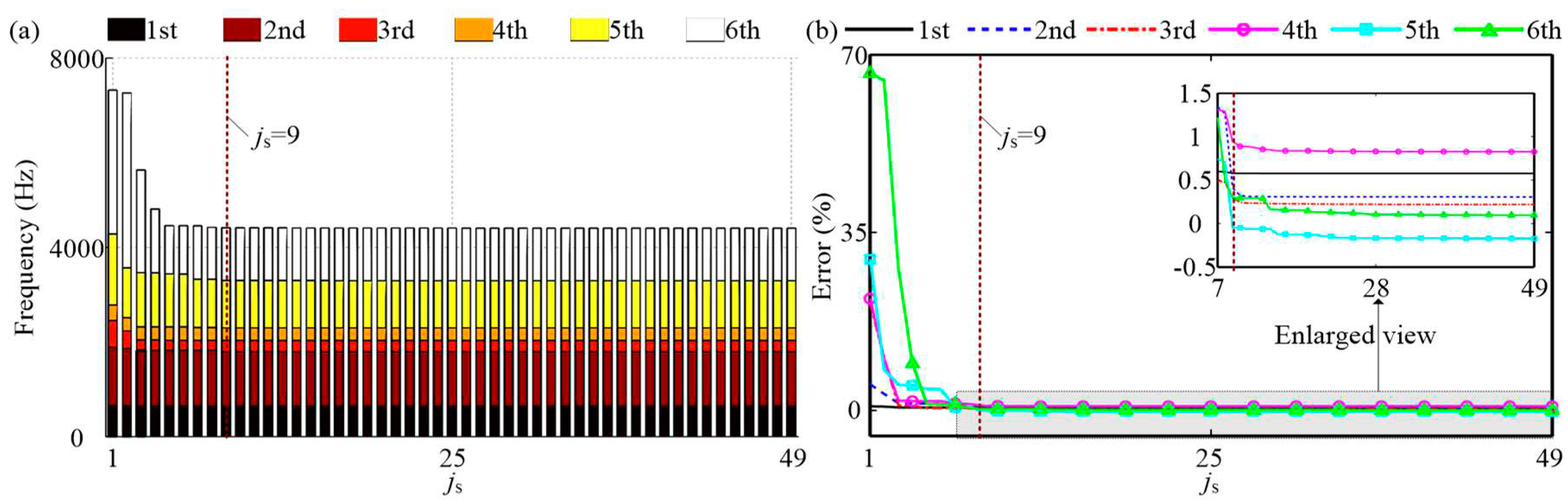
Figure 3.
Modal characteristics varying with n: (a) Campbell diagram, (b) modal shape under n=4000 rev/min.
Figure 3.
Modal characteristics varying with n: (a) Campbell diagram, (b) modal shape under n=4000 rev/min.
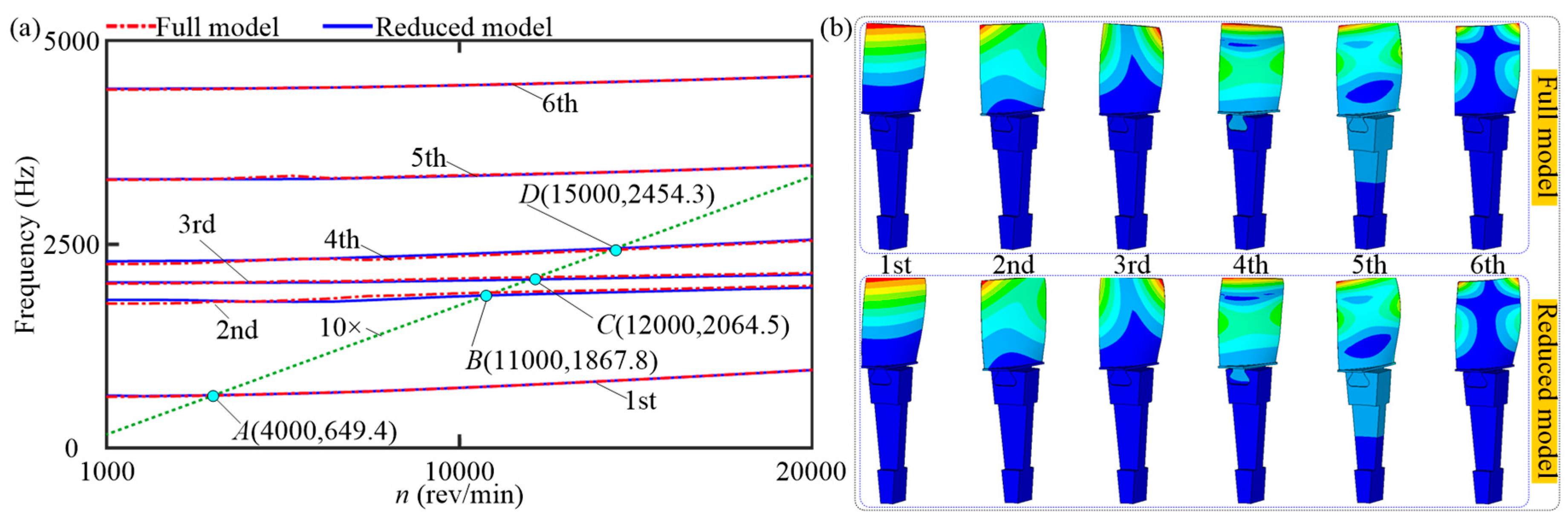
Figure 4.
Y-vibration of tip node 1: (a) spectrum cascades, (b) amplitude frequency responses, (c) fe vs. n, (d) k vs. n.
Figure 4.
Y-vibration of tip node 1: (a) spectrum cascades, (b) amplitude frequency responses, (c) fe vs. n, (d) k vs. n.
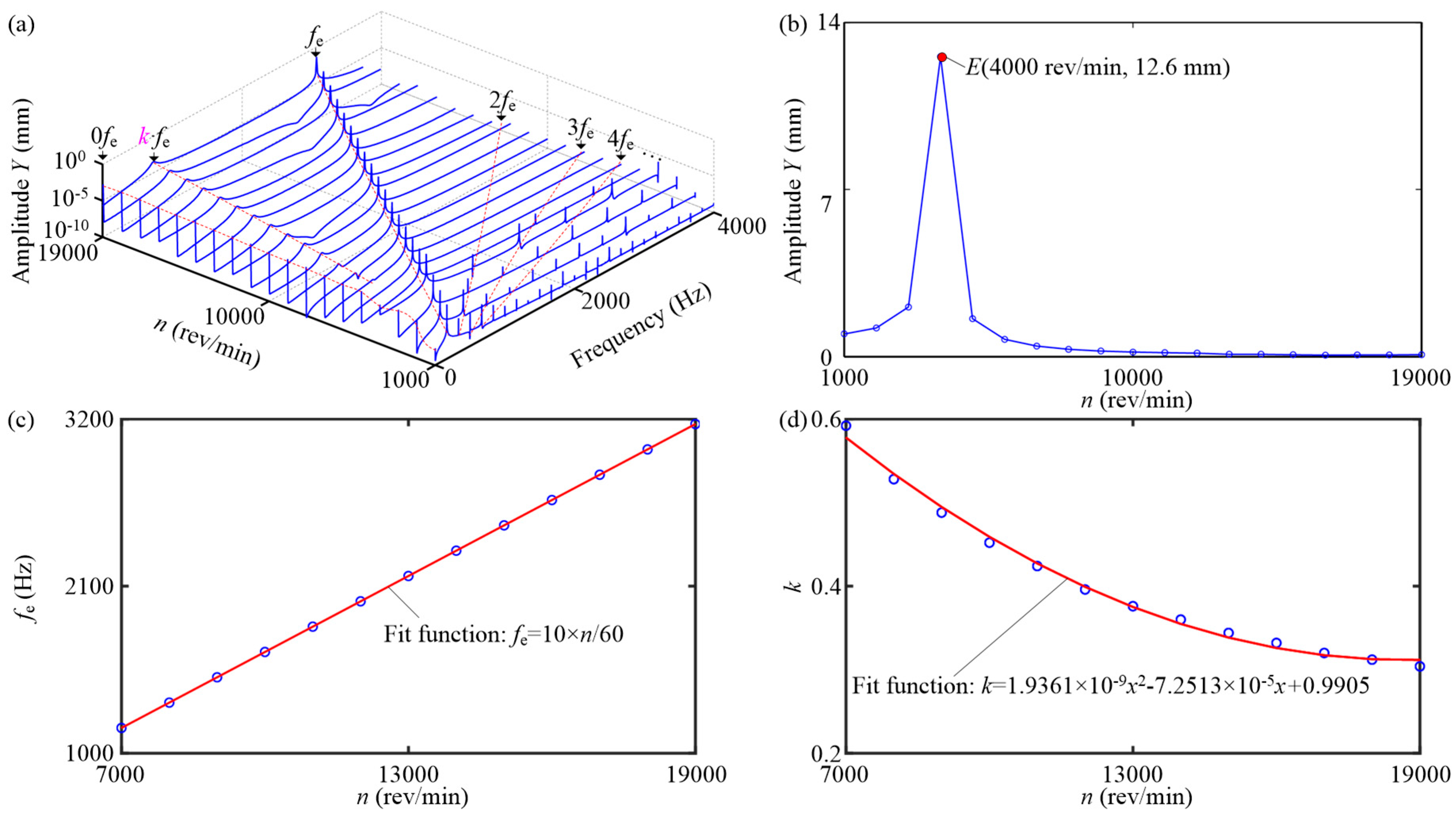
Figure 5.
Vibration responses of contact pressure for contact pair 1 under n=4000 rev/min: (a) time waveform, (b) spectrum cascades, (c) fe and corresponding amplitude vs. node order.
Figure 5.
Vibration responses of contact pressure for contact pair 1 under n=4000 rev/min: (a) time waveform, (b) spectrum cascades, (c) fe and corresponding amplitude vs. node order.
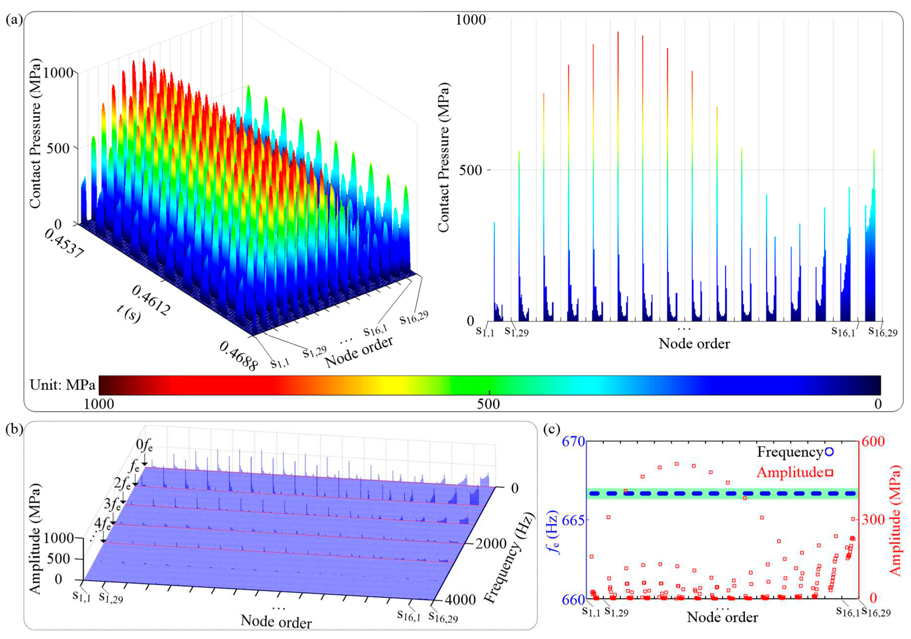
Figure 6.
Vibration responses of contact pressure for contact pair 1 under n=19000 rev/min: (a) time waveform, (b) spectrum cascades, (c) k⋅fe and corresponding amplitude vs. node order.
Figure 6.
Vibration responses of contact pressure for contact pair 1 under n=19000 rev/min: (a) time waveform, (b) spectrum cascades, (c) k⋅fe and corresponding amplitude vs. node order.
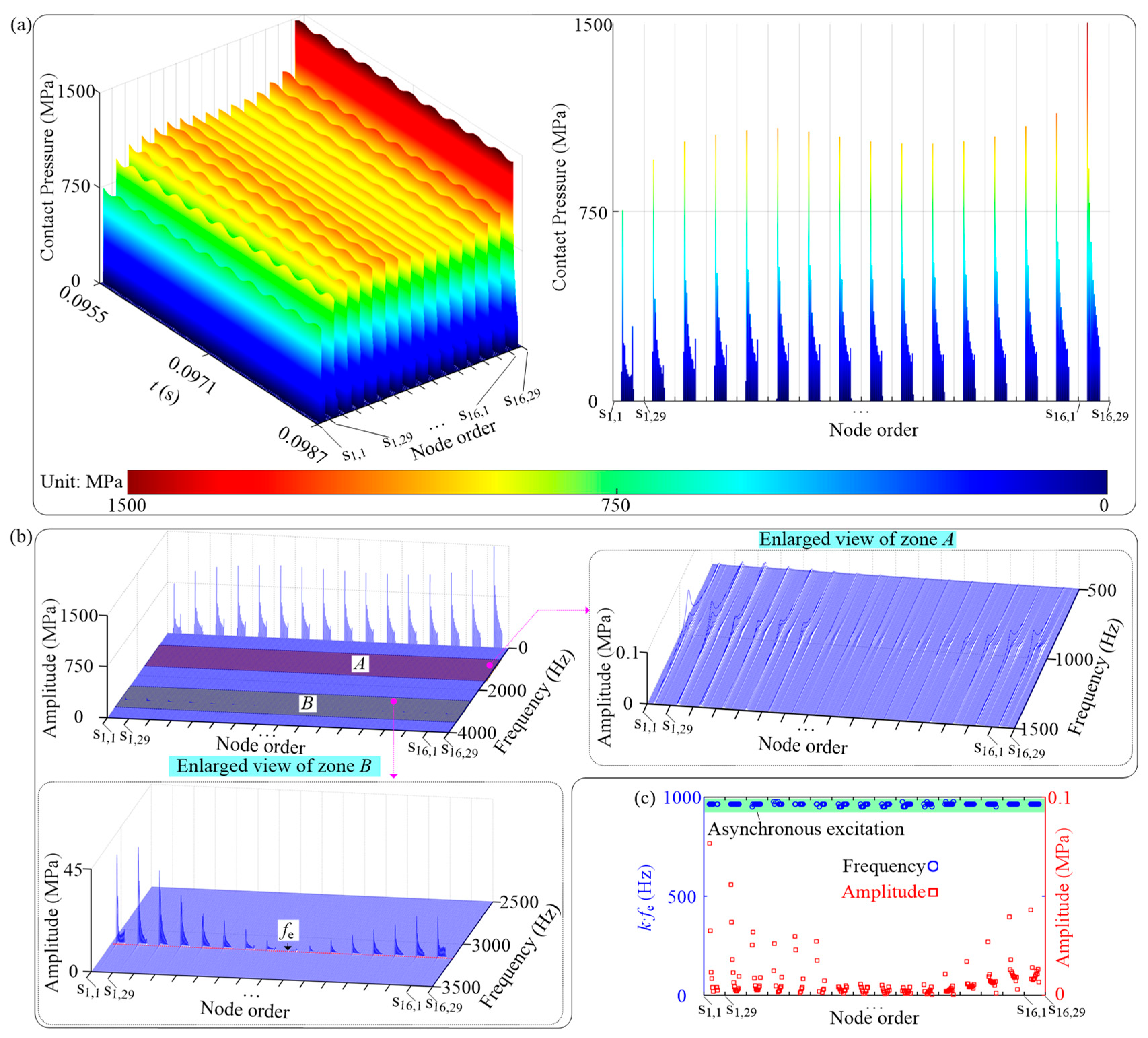
Figure 7.
Y-vibration characteristics of tip node 1: (a) spectrum cascades, (b) amplitude-frequency responses.
Figure 7.
Y-vibration characteristics of tip node 1: (a) spectrum cascades, (b) amplitude-frequency responses.
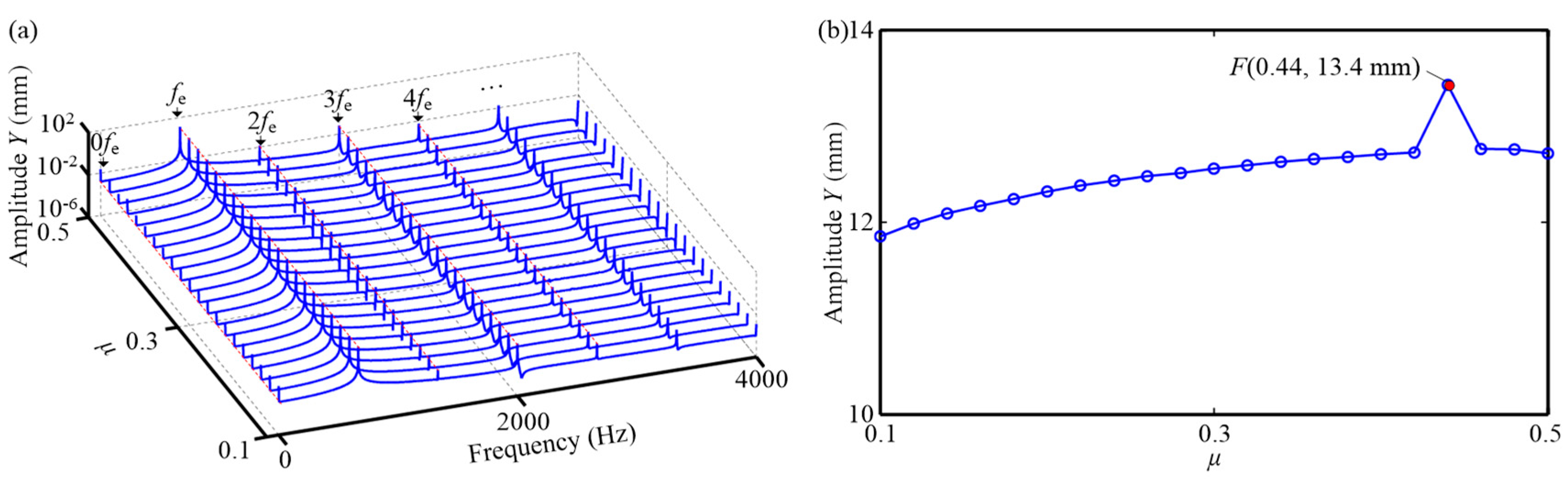
Figure 8.
Vibration responses of contact pressure for contact pair 1 under μ=0.1: (a) time waveform, (b) spectrum cascades, (c) fe and corresponding amplitude vs. node order.
Figure 8.
Vibration responses of contact pressure for contact pair 1 under μ=0.1: (a) time waveform, (b) spectrum cascades, (c) fe and corresponding amplitude vs. node order.
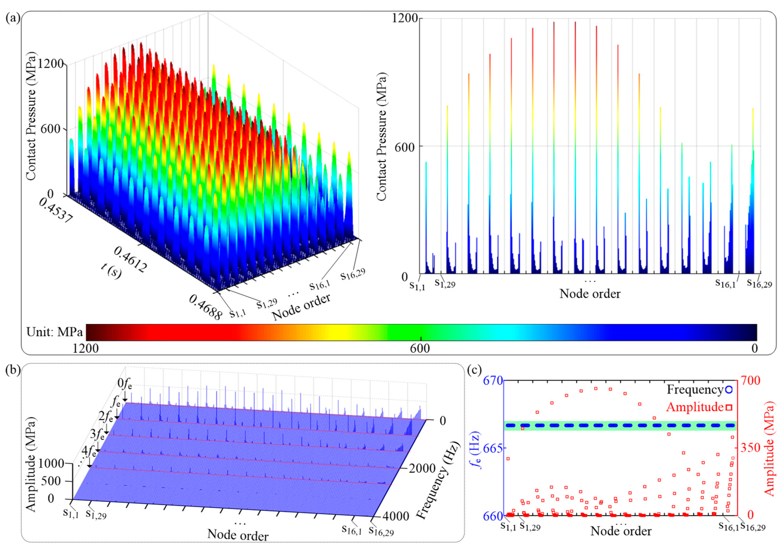
Figure 9.
Vibration responses of contact pressure for contact pair 1 under μ=0.44: (a) time waveform, (b) spectrum cascades, (c) fe and corresponding amplitude vs. node order.
Figure 9.
Vibration responses of contact pressure for contact pair 1 under μ=0.44: (a) time waveform, (b) spectrum cascades, (c) fe and corresponding amplitude vs. node order.
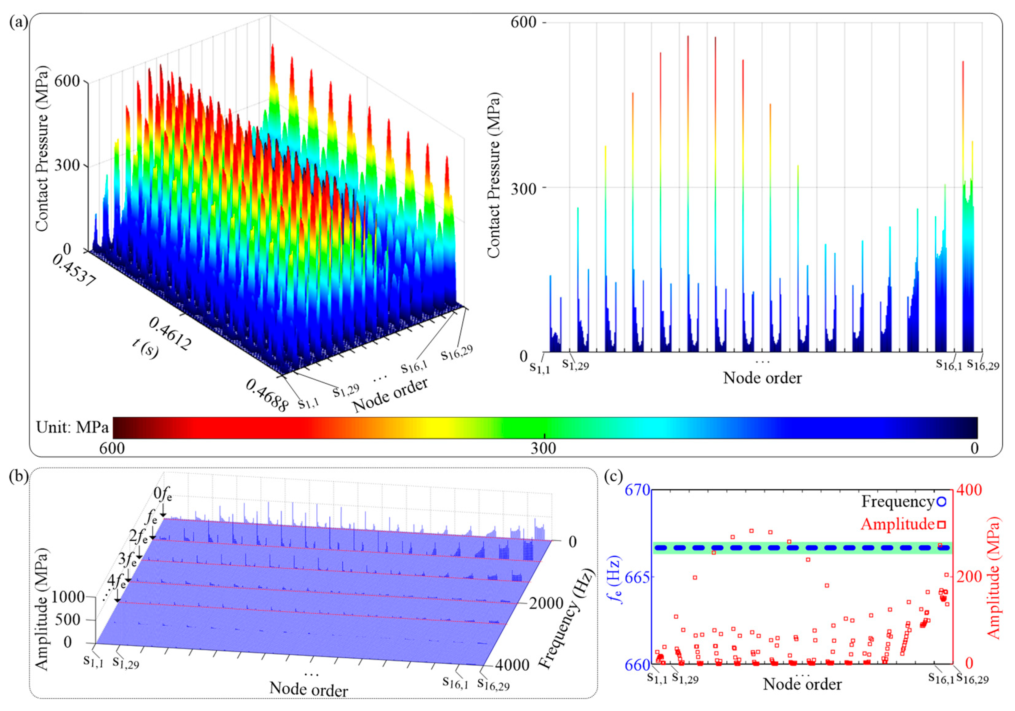

Table 1.
Simulation parameters.
| Cases | Analysis type | Gravity | Constant parameters | Varying parameters |
| 1 | Prestressed modal | No | n=4000 rev/min, μ=0.3, P0=0 MPa | js∈[1, 49], Δjs=1 |
| 2 | js=10, μ=0.3, P0=0 MPa | n∈[1000, 20000] rev/min, Δn=1000 rev/min | ||
| 3 | Transient | Yes | js=10, P0=0.1 MPa, μ=0.3 | fe=10⋅n/60, n∈[1000, 20000] rev/min, Δn=1000 rev/min |
| 4 | js=10, P0=0.1 MPa, fe=10⋅n/60,n=4000 rev/min | μ∈[0.1, 0.5], Δμ=0.02 |
Disclaimer/Publisher’s Note: The statements, opinions and data contained in all publications are solely those of the individual author(s) and contributor(s) and not of MDPI and/or the editor(s). MDPI and/or the editor(s) disclaim responsibility for any injury to people or property resulting from any ideas, methods, instructions or products referred to in the content. |
© 2023 by the authors. Licensee MDPI, Basel, Switzerland. This article is an open access article distributed under the terms and conditions of the Creative Commons Attribution (CC BY) license (http://creativecommons.org/licenses/by/4.0/).
Copyright: This open access article is published under a Creative Commons CC BY 4.0 license, which permit the free download, distribution, and reuse, provided that the author and preprint are cited in any reuse.


