1. Introduction
As wireless communication networks expand, base station antennas are critical components in these systems. However, they face challenges such as large physical dimensions and limited bandwidth [
1]. Dual-polarized antennas have obtained significant attention due to their advantages in polarization diversity and high isolation. Practically, various antenna designs can achieve dual polarization. Comment elements can include patch antennas [
2,
3], slot antennas [
4], or dipole antennas [
5,
6,
7,
8,
9,
10,
11,
12,
13,
14,
15,
16]. However, they may suffer from either limited bandwidth [
2,
3,
4] or high profile [
5,
6,
7]. Achieving miniaturization and widening bandwidth have emerged as the foremost challenges in developing dual-polarized antennas.
Dual-polarized planar dipole antennas have attracted considerable attention because of their wide bandwidth and pattern stability. Low-profile designs can be achieved using bowtie-shaped crossed dipole antennas and Huygens dipole antennas with profiles of 0.088
λ0 [
8] and 0.0483
λ0 [
9], respectively (where
λ0 represents the wavelength in free space at the center frequency). However, they can provide narrow -10-dB impedance bandwidths of only 15.6% [
8] and 0.462% [
9]. To enhance antenna bandwidth, parasitic elements are used in antenna design. The common parasitic element can be L-shaped metal strips [
10] or quadrangular loops [
11,
12]. They act as additional resonating elements, creating a coupling effect [
10] or adding a new resonant mode [
11,
12]. As a result, the overall bandwidth significantly improved. The parasitic U-shaped grooves are also utilized to broaden bandwidth [
13,
14]. Grooves can modify the current distribution on the main radiating element and thus improve the antenna impedance. However, the profile of those dipole designs is around a quarter wavelength due to the conventional conductor reflector. The profile is required to eliminate the effect of reflected electromagnetic waves from the reflector. This bulkiness increases the cost and may not be suitable for size-constrained applications.
Artificial magnetic conductors (AMC) have recently been developed to replace traditional conductors as a new reflector type for base station antennas. They exhibit properties of magnetic conductors with a zero-degree phase shift upon reflection. This characteristic enables them to reduce the antenna profile, leading to compact and low-profile antenna designs. In [
15] and [
16], low-profile dual-polarized dipole antennas can be realized using AMC reflectors with heights of 0.13λ
0 and 0.15λ
0. However, both designs suffer from strong surface waves, leading to decreased antenna gain [
15] or high cross-polarization at big angles [
16].
In this communication, a low-profile broadband dual-polarized dipole antenna using a novel AMC reflector is studied. Using the dispersion Brillouin diagram, the AMC is designed to suppress the surface-wave effect and decrease antenna height, leading to a high antenna efficiency and low antenna profile. The fork-shaped lines feed the antenna without a direct connection, giving a broad impedance bandwidth. The parasitic strips reduce cross-polarization. A prototype that operates in 2G/3G/LTE base station applications was designed and fabricated. The reflection coefficient, radiation pattern, antenna gain, and antenna efficiency are measured. Reasonable agreement between the measured and simulated results is obtained.
2. Antenna Design and Configuration
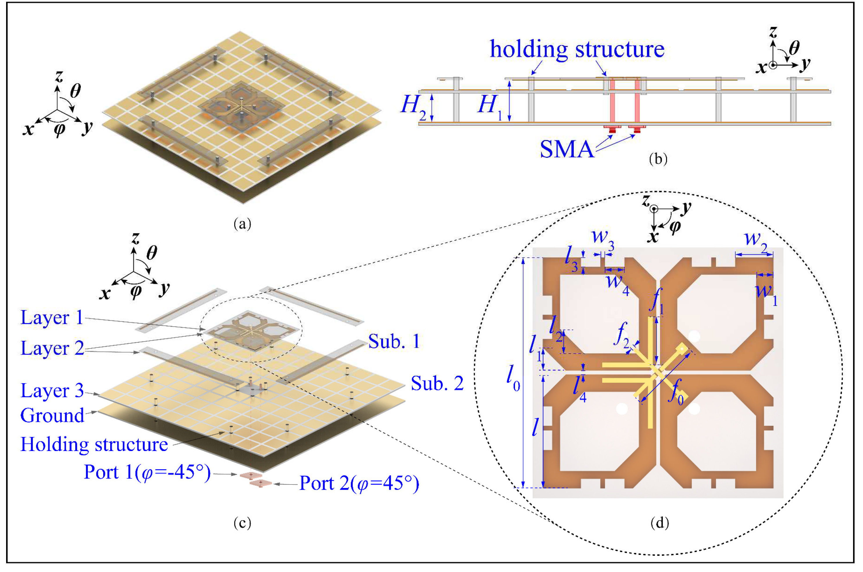
Figure 1 shows the configuration of the wideband dual-polarized antenna. With reference to
Figure 1a,b, this antenna comprises crossed-dipoles, double-layer AMC, fork-shaped feeding structures, and parasitic strips. Two crossed dipoles are positioned perpendicularly with slant angles of
φ = ± 45° and are represented as dipoles 1 and 2.
Figure 1c shows the exploded view of the proposed antenna. It can be seen from the figure that the feeding lines and crossed dipoles are printed on Layer1 and 2 of substrate 1 (Sub. 1), respectively.
Figure 1d zooms in view of the arms of dipoles and feeding structures. As can be seen from the figure, each arm of the dipole is a hexagonal ring with a width of
w1 = 3.6 mm and four mirror-symmetrical etched slots. It should be mentioned that one of the dipole arms is soldered directly to the feeding structures, while the other arm is fed via space coupling. This method is designed to obtain a wide -15-dB impedance matching bandwidth. The novel AMC consists of two metal layers, one substrate, and air layers. Periodic patches are its first metal layer printed on Layer 3 of Sub. 2 with the interval gap of
g = 2 mm and patch width of
w = 13 mm. The second metal layer is aluminum ground. Sub. 1 and Sub. 2 are FR4 substrates (
εr = 4.4, tan
δ = 0.02). Crossed dipoles are placed at the height of 5.5 mm from the AMC surface. Plastic pins are used to locate layers precisely.
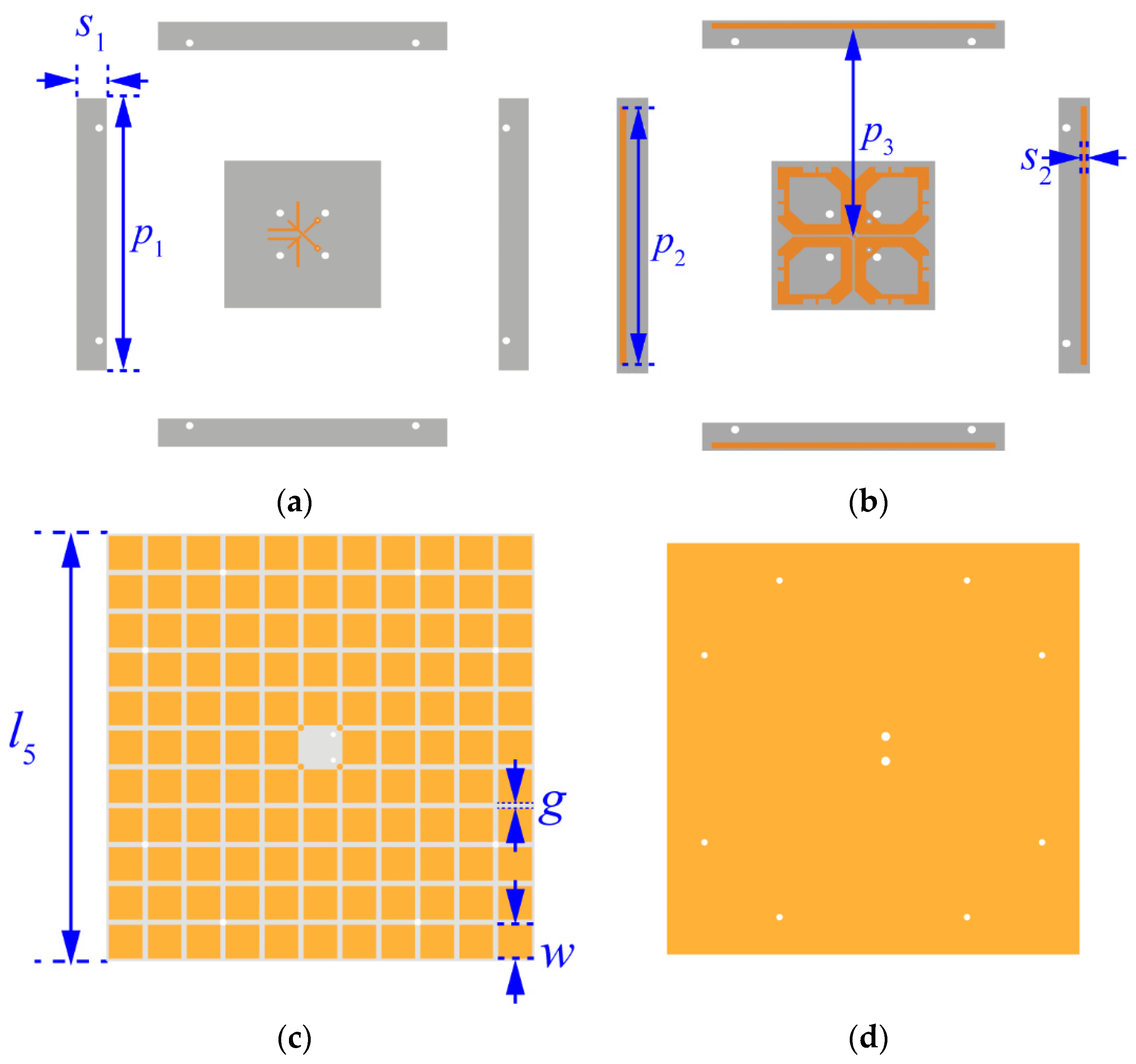
Figure 2 shows the different layers of the dual-polarized antenna. With reference to the figure, our parasitic strips are printed on layer 2 of substrate1 to reduce cross-polarization.
3. Analysis and Discussion
3.1. In-Phase Reflection Bandwidth of the AMC Unit
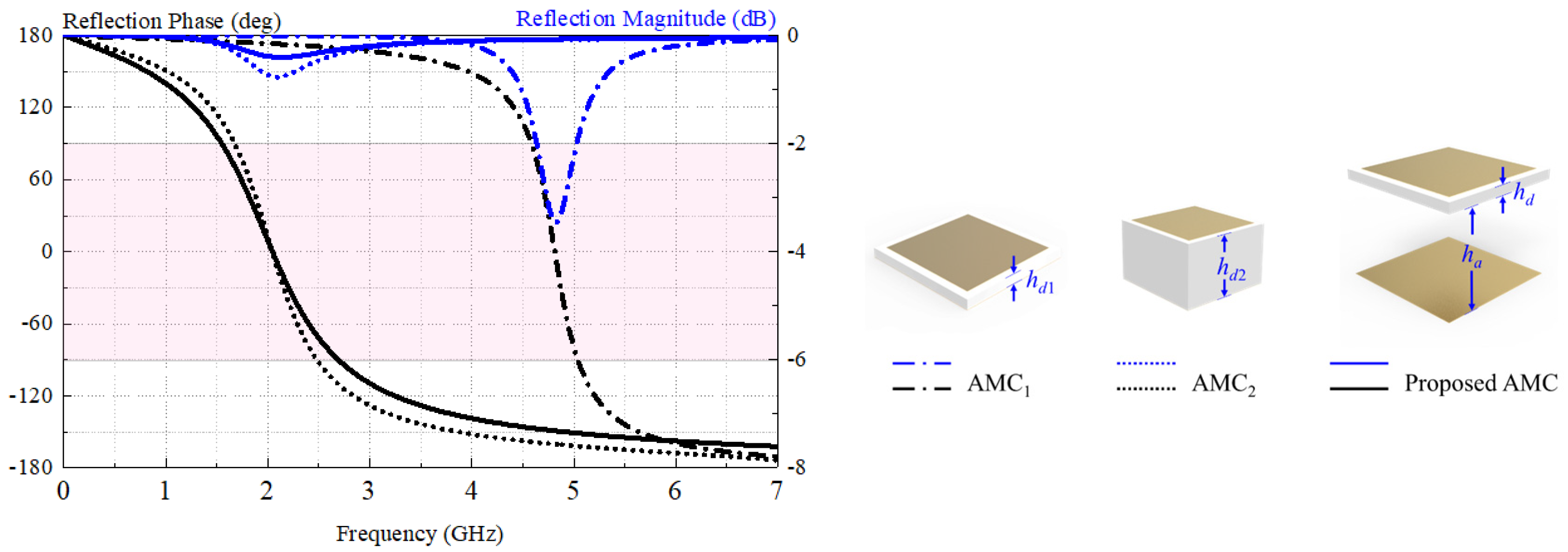
Figure 3 shows the configurations and reflection coefficients of different AMC units. The proposed AMC is a patch-typed with a patch width of
w = 13 mm, a substrate-layer height of
hd = 1.2 mm (0.0088
λ0), and an air-layer height of
ha = 12 mm(0.088
λ0). AMC
1 and AMC
2, which are conventional AMCs with the same patch size and gap width but different substrate-layer heights (
hd1 = 1.2 mm,
hd2 = 9.5 mm), were simulated for comparison. Generally, the in-phase reflection bandwidth is the frequency range in which the reflection phase is between -π/2 and π/2. With reference to the figure, the in-phase reflection bandwidths are 9.8%, 39.4%, and 54.7% for AMC1 (4.57-5.04 GHz), AMC2 (1.67-2.49 GHz), and the proposed AMC (1.54-2.70 GHz), respectively. Compared with the proposed AMC, AMC
1 lacks the air layer, giving a zero-phase reflection frequency of 4.82 GHz that is out of the operating bandwidth of 2G/3G/LTE. It is worth mentioning that AMC
2 has almost the same zero-phase reflection frequency, but has a narrower in-phase bandwidth and worse reflection coefficient than the proposed AMC. Therefore, our AMC is a good alternative to the metal ground due to its wideband.
3.2. Dispersion Brillouin Diagram of the AMC Unit
Generally, a surface wave will be excited when electromagnetic waves reflect from the ground, deteriorating antenna performance.
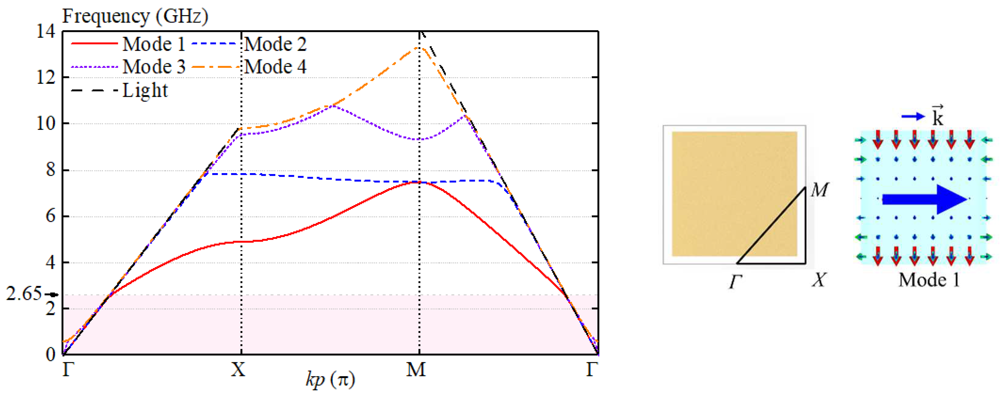
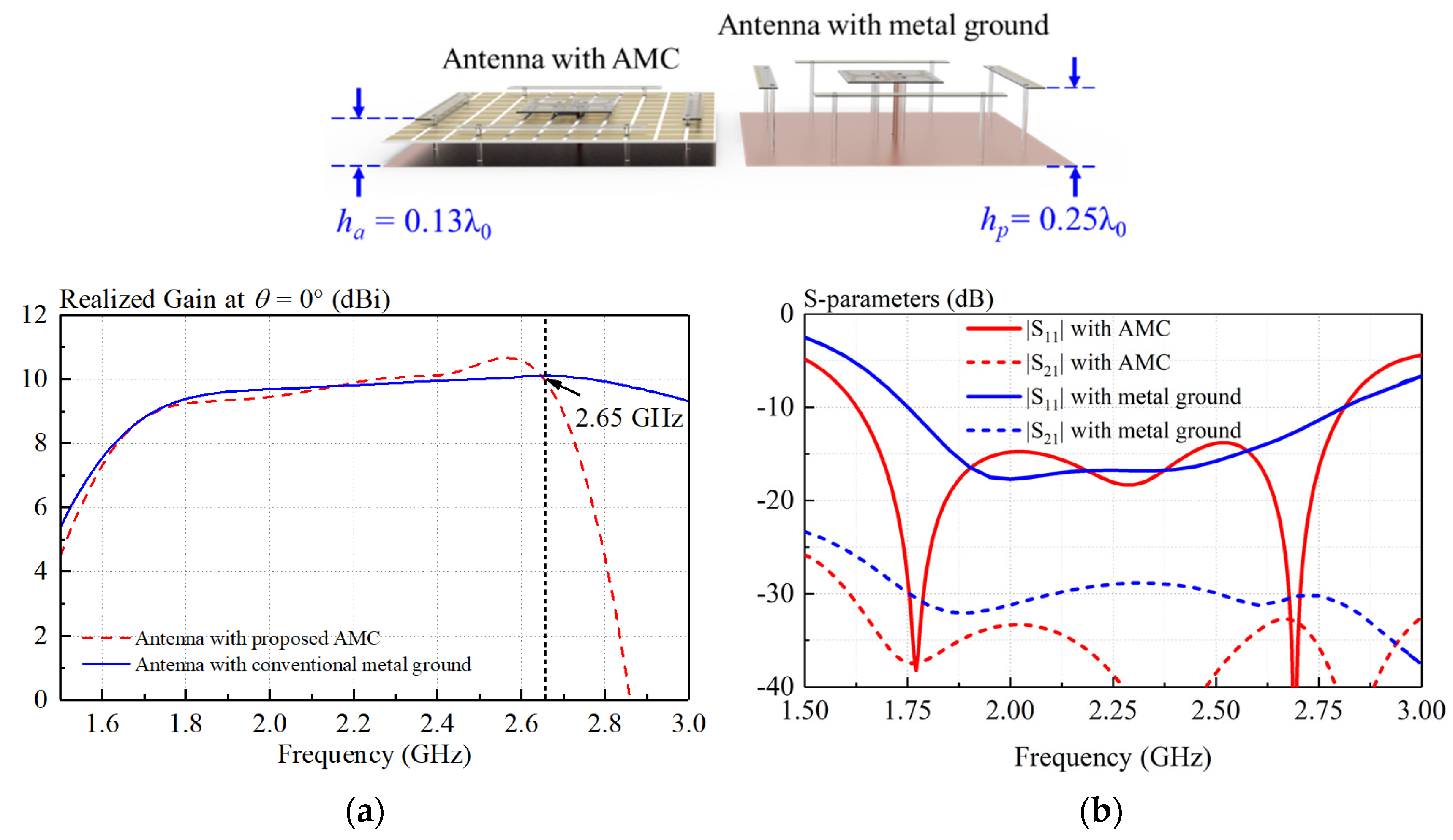
Figure 4 shows the dispersion curves of the proposed AMC unit. With reference to the figure, the electromagnetic wave under 2.65 GHz is served as a slow wave and bounded in the AMC surface. However, as increasing the frequency beyond 2.65 GHz, the electromagnetic wave gradually becomes as a fast wave and leaks into free space. Consequently, the antennas loading proposed AMC and conventional metal ground have nearly the same realized gain before 2.65 GHz as shown in
Figure 5a.
Figure 5b shows the simulated S-parameters of the antenna. It can be seen from the figure that both reflection coefficient and isolation are improved by using the AMC. It should be mentioned that proposed antenna can effectively decrease antenna profile from 0.25λ
0 to 0.13λ.
3.3. Evolution of Antenna
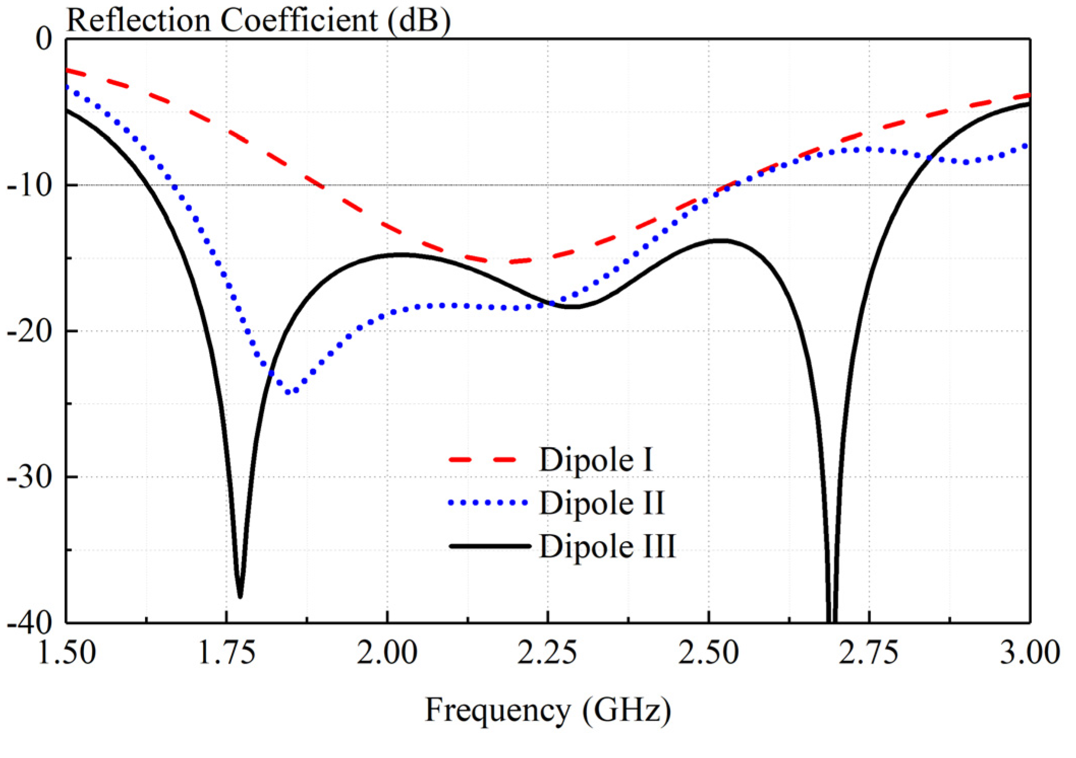
Figure 6 shows the design evolution of crossed dipole. With reference to the figure, the arms of Dipole I are rectangular rings with a width of 3.6mm. Dipole II is obtained by cutting arm corners and centers of Dipole I. Finally, Dipole III is obtained by adding rectangular slots on the radiating dipole arms.
Figure 7 compares the simulated reflected coefficient of Dipole I, Dipole II, and Dipole III. Dipole I has a -10-dB impedance bandwidth of 29.9% (1.88-2.54 GHz). As shown in the figure, the corner and center cuts in Dipole II effectively improve the impedance matching, especially in the lower-frequency band. After cutting, the -10-dB impedance bandwidth increased to 41.7% (1.67-2.55 GHz). In Dipole III, the introduced rectangular slots further improve the impedance matching in the high-frequency band, resulting in a wide impedance passband of 55.4% (1.58 –2.79 GHz).
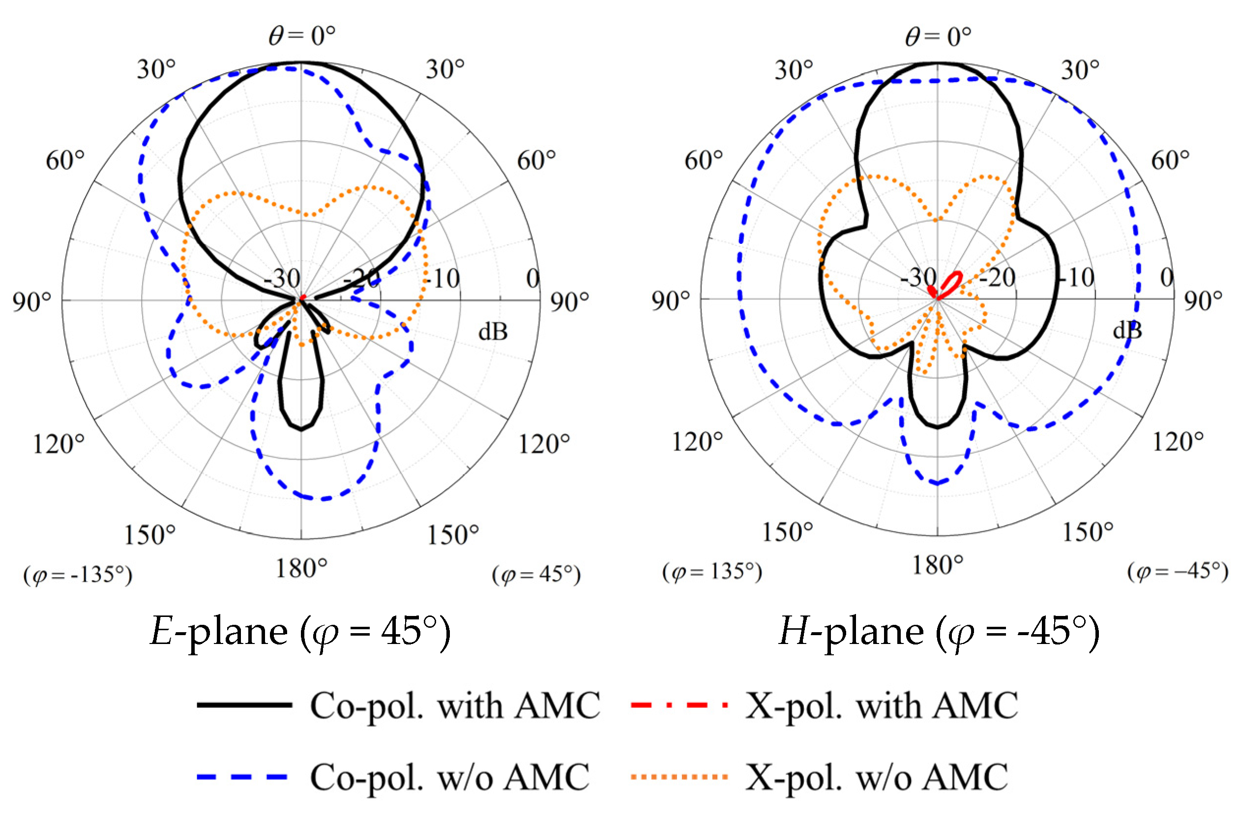
Figure 8 shows the comparison of simulated radiation patterns between the crossed-dipole antenna with/without four parasitic strips. With reference to the figure, significant improvements in both
E- and
H-plane radiation patterns can be obtained by loading strips. It is worth mentioning that, using this method, the cross-polar fields in the two principal cutting planes decrease by more than 12 dB.
4. Results
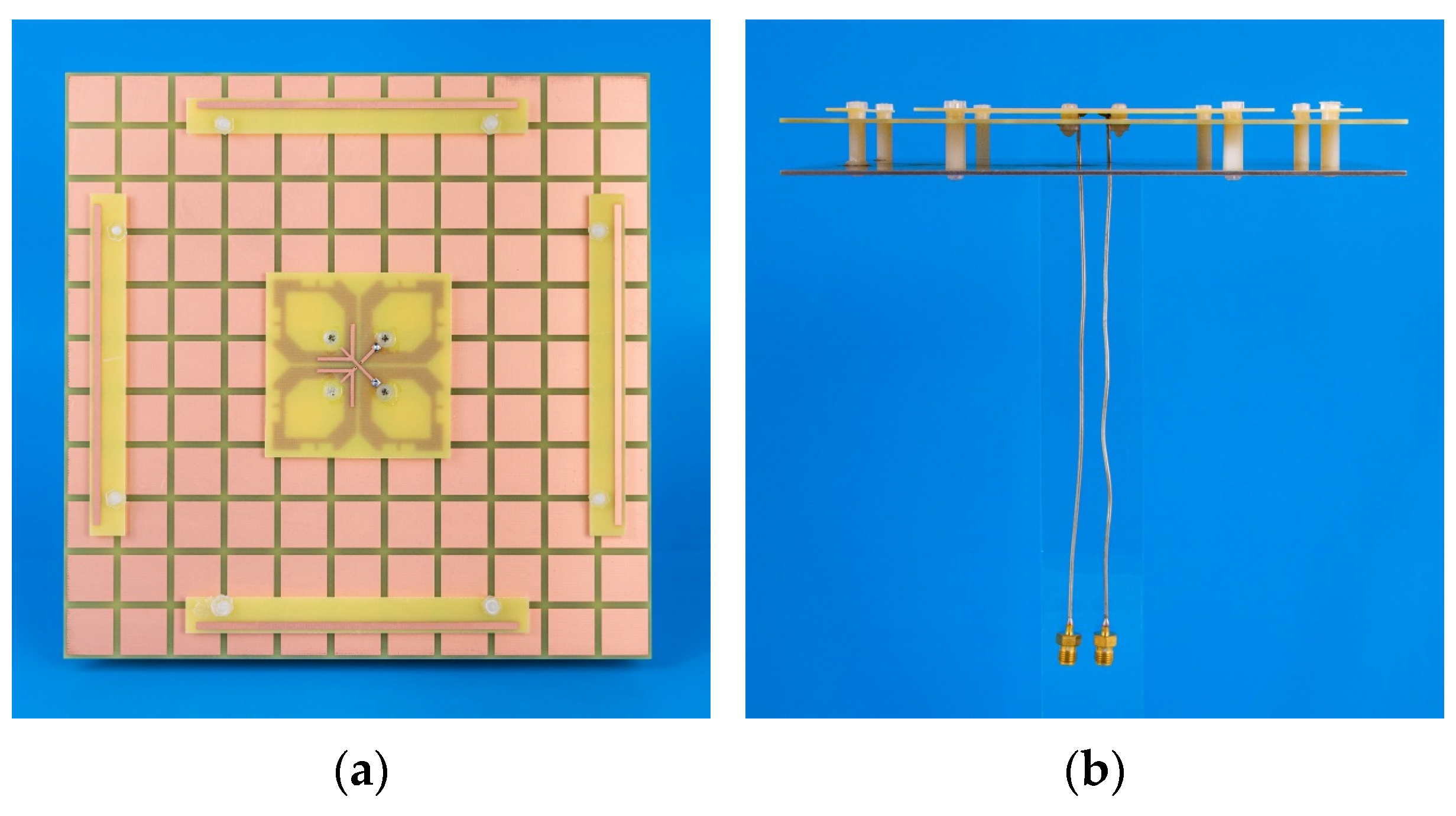
To verify the idea, a prototype of the proposed antenna was fabricated, as shown in
Figure 9.
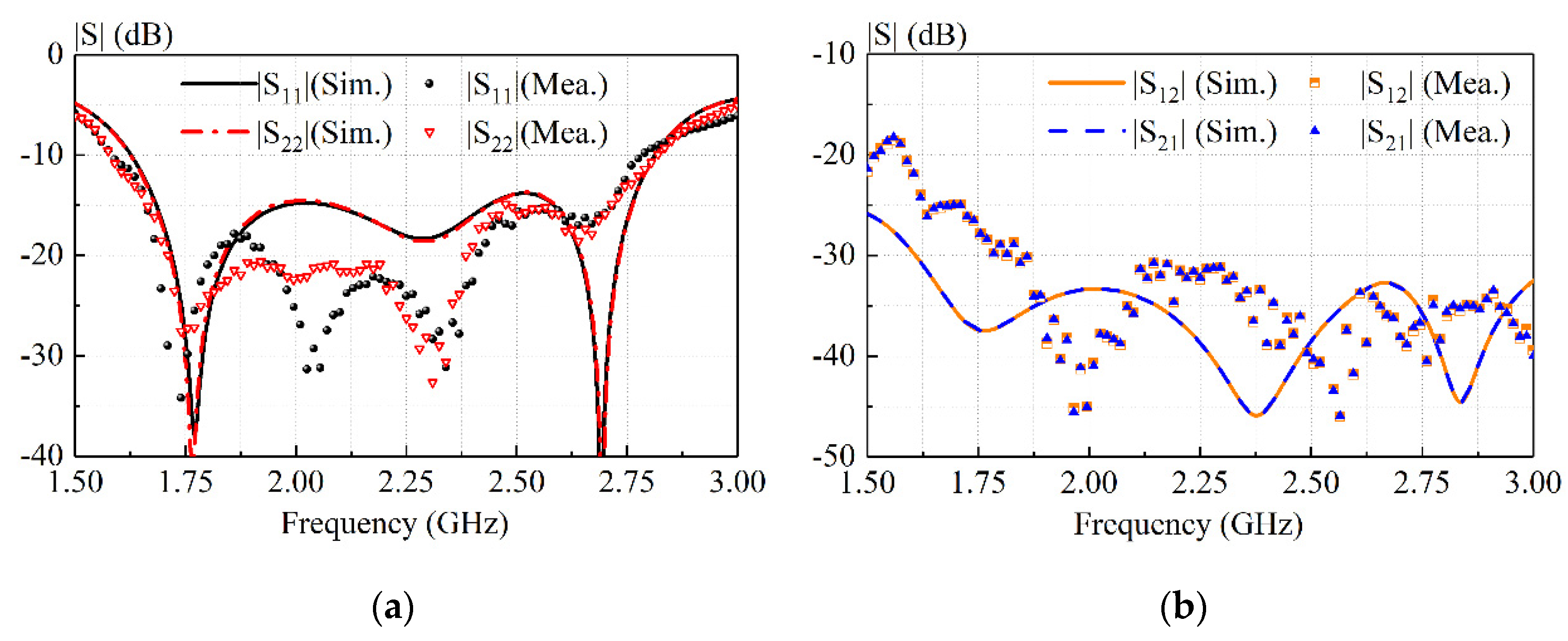
Figure 10 shows the measured and simulated S-parameter of our antenna. With reference to
Figure 10a, the measured and simulated −10-dB impedance bandwidths (|S11| ≤ −10 dB) are 54.05% (1.62–2.82 GHz) and 55.37% (1.58 –2.79 GHz), respectively. As shown in
Figure 10b, the isolations in both simulation and measurement are almost greater than 30dB across the impedance-matching passband.
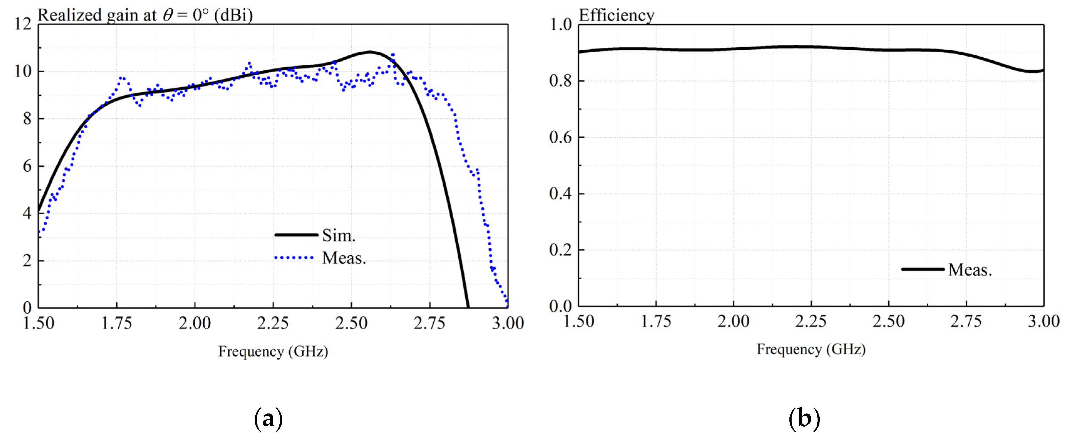
Figure 11a presents simulated and measured realized gains of the proposed antenna at
θ = 0°. With reference to the figure, reasonable agreement can be found between simulated and measured results. The ripple in measurement is less than 1dB caused by the experimental imperfections. The measured gain varies between 8.3 to 10.8 dBi over the frequency range (1.62–2.82 GHz) shown in
Figure 10a.
Figure 11b shows the measured antenna efficiency of the low-profile crossed dipole antenna. As can be observed from
Figure 11b, the measured antenna efficiency is higher than 90% across the entire operating band.
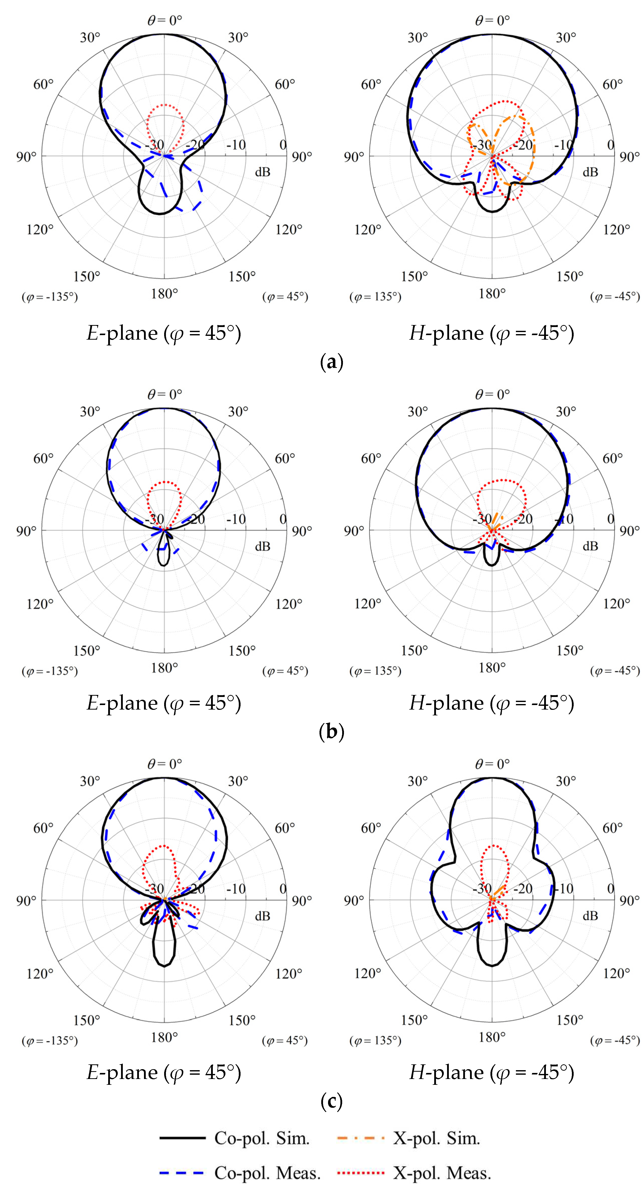
Figure 12 shows the measured and simulated normalized radiation patterns in two principal cutting planes. Reasonable agreement can be found between simulations and measurements. As shown in the figure, stable radiation patterns can be found at three different frequencies. The simulated cross-polar field is almost lower than -30 dB. It can be observed from the figure that the co-polar field is 10 dB higher than the cross-polar field over a wide range of angles (-60° <
θ < 60°) in measurements. Results of Port 1 are only shown due to the geometric symmetry of our crossed-dipole antenna.
Table 1 compares our antenna with reported crossed dipole antennas. With reference to the table, the antennas in [
8] and [
9] have an extremely low antenna height but a narrow bandwidth and low gain. The designs in references [
11,
12,
13,
14] have a higher profile. The antennas in references [
14] and [
15] have similar profiles, but their antenna gains are lower than the proposed antenna. Compared with listed base-station antennas, the proposed antenna outperforms in overall performance. It is a good candidate for base-station applications.
5. Conclusions
A wideband low-profile crossed dipole antenna with a novel AMC has been investigated. By introducing the AMC as antenna ground, the profile can be effectively decreased to 0.12λ0. In addition, four parasitic metal strips have been introduced to reduce the cross- polar field and thus increase antenna gain in its high-frequency impedance passband. To verify the idea, a prototype has been simulated, fabricated, and measured. A measured overlapping bandwidth of 55.4%(1.58 –2.79 GHz) has been obtained. Its maximum measured realized gain is 10.8 dBi at 2.6 GHz. Also, a stable gain and radiation pattern have been observed. The prototype has a measured isolation of ~30dB. It should be mentioned that its cross-polarization level of is more than -10dB over a wide range of angles (-60° < θ < 60°). Finally, these advantages enable the proposed antenna to be potentially applied to the integrated design of 2G/3G/LTE base station antennas.
Author Contributions
Conceptualization, methodology, Zhiyi Zhang and Hao Feng; validation, Mengyuan Li; formal analysis, Qunhao Zhang; writing—review and editing, Yulin Zhao; project administration, Jiahui Fu. All authors have read and agreed to the published version of the manuscript.
Funding
This research was funded by the National Natural Science Foundation of China under Grant 62171165.
Institutional Review Board Statement
Not applicable.
Informed Consent Statement
Not applicable.
Data Availability Statement
Not applicable.
Conflicts of Interest
The authors declare no conflict of interest. The funders had no role in the design of the study; in the collection, analyses, or interpretation of data; in the writing of the manuscript; or in the decision to publish the results.
References
- Huang, C.; Zappone, A.; Alexandropoulos, G.C.; Debbah, M.; Yuen, C. Reconfigurable intelligent surfaces for energy efficiency in wireless communication. IEEE Trans. Wirel. Commun. 2019, 18, 4157–4170. [Google Scholar] [CrossRef]
- Li, Q.L.; Cheung, S.W.; Zhou, C.F. A low-profile dual-polarized patch antenna with stable radiation pattern using ground-slot groups and metallic ground wall. IEEE Trans. Antennas Propag. 2017, 65, 5061–5068. [Google Scholar] [CrossRef]
- Zhang, X.; Xue, D.; Ye, L.; Pan, Y.; Zhang, Y. Compact dual-band dual-polarized interleaved two-beam array with stable radiation pattern based on filtering elements. IEEE Trans. Antennas Propag. 2017, 65, 4566–4575. [Google Scholar] [CrossRef]
- Liu, Y.; Li, X.; Yang, L.; Liu, Y. A dual-polarized dual-band antenna with omni-directional radiation patterns. IEEE Trans. Antennas Propag. 2017, 65, 4259–4262. [Google Scholar] [CrossRef]
- Dai, X.W.; Ding, C.; Zhu, F.; Liu, L.; Luo, G.Q. Broadband dual-polarized element with rotated sleeve arms for compact dual-band antenna. IEEE Antennas Wireless Propag. Lett. 2021, 20, 2519–2523. [Google Scholar] [CrossRef]
- Wu, R.; Chu, Q.X. A wideband dual-polarized antenna for LTE700/GSM850/GSM900 applications. IEEE Antennas Wireless Propag. Lett. 2017, 16, 2098–2101. [Google Scholar] [CrossRef]
- Huang, H.; Liu, Y.; Gong, S.X. A dual-broadband, dual-polarized base station antenna for 2G/3G/4G applications. IEEE Antennas Wireless Propag. Lett. 2017, 16, 1111–1114. [Google Scholar] [CrossRef]
- Zhai, H.; Zhang, K.; Yang, S.; Feng, D. A low-profile dual-band dual-polarized antenna with an AMC surface for WLAN applications. IEEE Antennas Wireless Propag. Lett. 2017, 16, 2692–2695. [Google Scholar] [CrossRef]
- Tang, M.C.; Wu, Z.T.; Shi, T.; Zeng, H.; Lin, W.; Ziolkowski, R.W. Dual-linearly polarized, electrically small, low-profile, broadside radiating, Huygens dipole antenna. IEEE Trans. Antennas Propag. 2018, 66, 3877–3885. [Google Scholar] [CrossRef]
- Yu, W.; Lin, H.; Liao, B.; Duan, W. A compact dual-polarized low-pass filtering antenna with wideband out-of-band rejection. IEEE Antennas Wireless Propag. Lett. 2021, 20, 2329–2333. [Google Scholar] [CrossRef]
- Wen, D.L.; Zheng, D.Z.; Chu, Q.X. A wideband differentially fed dual-polarized antenna with stable radiation pattern for base stations. IEEE Trans. Antennas Propag. 2017, 65, 2248–2255. [Google Scholar] [CrossRef]
- Ding, C.F.; Zhang, X.Y.; Zhang, Y.; Pan, Y.M.; Xue, Q. Compact broadband dual-polarized filtering dipole antenna with high selectivity for base-station applications. IEEE Trans. Antennas Propag. 2018, 66, 5747–5756. [Google Scholar] [CrossRef]
- Ding, C.F.; Zhang, X.Y.; Yu, M. Simple dual-polarized filtering antenna with enhanced bandwidth for base station applications. IEEE Trans. Antennas Propag. 2020, 68, 4354–4361. [Google Scholar] [CrossRef]
- Cui, Y.; Wu, L.; Li, R. Bandwidth enhancement of a broadband dual-polarized antenna for 2G/3G/4G and IMT base stations. IEEE Trans. Antennas Propag. 2018, 66, 7368–7373. [Google Scholar] [CrossRef]
- Li, M.; Li, Q.L.; Wang, B.; Zhou, C.F.; Cheung, S.W. A low-profile dual-polarized dipole antenna using wideband AMC reflector. IEEE Trans. Antennas Propag. 2018, 66, 2610–2615. [Google Scholar] [CrossRef]
- Nasser, S.S.S.; Chen, Z.N. Low-profile broadband dual-polarization double-layer metasurface antenna for 2G/3G/LTE cellular base stations. IEEE Trans. Antennas Propag. 2022, 70, 75–83. [Google Scholar] [CrossRef]
Figure 1.
Configuration of the dual-polarized antenna. (a) Perspective view. (b) Side view. (c) Exploded view. (d) Zoomed view of crossed dipole antenna. H1 = 17.5 mm, H2 = 12 mm, w1 = 3.6 mm, w2 = 7.3 mm, w3 = 1.65 mm, w4 = 4 mm, l = 23.5 mm, l0 = 52 mm, l1 = 4.8 mm, l2 = 5 mm, l3 = 2 mm, l4 = 0.8 mm, f0 = 14 mm, f1 = 10.5 mm, f2 = 0.83 mm.
Figure 2.
Different layers of the dual-polarized antenna. (a) Substrate1 Layer 1 (b) Substrate1 Layer 2 (c) Substrate2 Layer 3 (d) Aluminum Ground. L5 = 65 mm, w = 13 mm, g = 2 mm, S1 = 10 mm, S2 = 2 mm, P1 = 96 mm, P2 = 90 mm, P3 = 72 mm.
Figure 2.
Different layers of the dual-polarized antenna. (a) Substrate1 Layer 1 (b) Substrate1 Layer 2 (c) Substrate2 Layer 3 (d) Aluminum Ground. L5 = 65 mm, w = 13 mm, g = 2 mm, S1 = 10 mm, S2 = 2 mm, P1 = 96 mm, P2 = 90 mm, P3 = 72 mm.
Figure 3.
Reflection coefficients and Configurations of different AMC units.
Figure 3.
Reflection coefficients and Configurations of different AMC units.
Figure 4.
The dispersion curves of the proposed AMC unit. The illustrations are the electric field distributions. The blue arrow indicates the direction of propagating wave.
Figure 4.
The dispersion curves of the proposed AMC unit. The illustrations are the electric field distributions. The blue arrow indicates the direction of propagating wave.
Figure 5.
Comparison between crossed-dipole antenna with AMC and that with conventional metal ground. (a) Simulated realized gain (b) simulated S-parameters.
Figure 5.
Comparison between crossed-dipole antenna with AMC and that with conventional metal ground. (a) Simulated realized gain (b) simulated S-parameters.
Figure 6.
Design evolution. Dipole I (a conventional crossed-dipole antenna), Dipole II (Dipole I with corners and center cut), Dipole III (crossed dipole in the proposed antenna).
Figure 6.
Design evolution. Dipole I (a conventional crossed-dipole antenna), Dipole II (Dipole I with corners and center cut), Dipole III (crossed dipole in the proposed antenna).
Figure 7.
Simulated reflection coefficients of Dipole I, Dipole II, and Dipole III.
Figure 7.
Simulated reflection coefficients of Dipole I, Dipole II, and Dipole III.
Figure 8.
Comparison of simulated radiation patterns between the antennas with/without parasitic strips.
Figure 8.
Comparison of simulated radiation patterns between the antennas with/without parasitic strips.
Figure 9.
Photograph of proposed antenna. (a) Top view. (b) Side view.
Figure 9.
Photograph of proposed antenna. (a) Top view. (b) Side view.
Figure 10.
Measured and simulated S-parameters of proposed antenna.
Figure 10.
Measured and simulated S-parameters of proposed antenna.
Figure 11.
Measurements and simulations of proposed antenna. (a) Realized gain. (b) Antenna efficiency.
Figure 11.
Measurements and simulations of proposed antenna. (a) Realized gain. (b) Antenna efficiency.
Figure 12.
Measured and simulated radiation patterns of proposed antenna Port 1. (a) 1.6 GHz, (b) 2.1 GHz, and (c) 2.6 GHz. Results of Port 1 are only shown due to geometric symmetry of our crossed-dipole antenna.
Figure 12.
Measured and simulated radiation patterns of proposed antenna Port 1. (a) 1.6 GHz, (b) 2.1 GHz, and (c) 2.6 GHz. Results of Port 1 are only shown due to geometric symmetry of our crossed-dipole antenna.
Table 1.
Comparison of crossed-dipole antennas.
Table 1.
Comparison of crossed-dipole antennas.
| Ref. |
-10-dB impedance Bandwidth (GHz) |
Gain (dBi) |
Isolation (dB) |
Profile (λ0) |
| [8] |
15.6% (2.36-2.76 GHz) |
4.6-7.2 |
>22 |
0.09 |
| [9] |
0.46% (1.48-1.55 GHz) |
<2.2 |
>26 |
0.05 |
| [11] |
52.2% (1.70-2.90 GHz)
(VSWR < 1.5) |
8.2-9.4 |
>26 |
0.26 |
| [12] |
48.7% (1.66-2.73 GHz) |
7.8-8.5 |
>34 |
0.23 |
| [13] |
65.3% (1.67-3.29 GHz) |
7.8-8.8 |
>32 |
0.26 |
| [14] |
74.9% (1.31-2.88 GHz) |
7.8~9.1 |
>30 |
0.35 |
| [15] |
56.3% (1.67-2.98 GHz) |
6.7-7.6 |
>25 |
0.13 |
| [16] |
49.4% (1.69-2.80 GHz) |
6.8-9.8 |
>27 |
0.15 |
| This work |
55.4% (1.58–2.79 GHz) |
8.3-10.8 |
>30 |
0.13 |
|
Disclaimer/Publisher’s Note: The statements, opinions and data contained in all publications are solely those of the individual author(s) and contributor(s) and not of MDPI and/or the editor(s). MDPI and/or the editor(s) disclaim responsibility for any injury to people or property resulting from any ideas, methods, instructions or products referred to in the content. |
© 2023 by the authors. Licensee MDPI, Basel, Switzerland. This article is an open access article distributed under the terms and conditions of the Creative Commons Attribution (CC BY) license (http://creativecommons.org/licenses/by/4.0/).
