
Submitted:
20 April 2023
Posted:
20 April 2023
You are already at the latest version
Abstract
The reliability of Underwater Wireless Sensor Networks (UWSNs) is measured in terms of energy consumption (EC), end-to-end delay(E2E) and packet delivery ratio (PDR). The adverse effects of channel may cause data loss. Reducing delay up to possible extend improves the reliability of the network, also increasing the number of nodes in a particular network increase reliability. Besides, increasing the number of nodes improve reliability but also increase power consumption. In order to overcome these shortcomings, the two routing protocols are proposed in this paper, namely Delay and Reliability Aware Routing (DRAR) protocol and Cooperative Delay and Reliability Aware Routing (Co-DRAR) protocol for UWSNs. In DRAR protocol, network is divided into two equal regions where two sink nodes(SNs) are positioned at upper region of the network and two SNs are placed at the mid region of the network. The protocol choose the relay node based on residual energy (RE), distance and Bit Error Rate (BER). These parameters protect the data packets from corruption and also provide stable path (where nodes remain active for longer period and do not die quickly). The protocol uses single link and may get worse sometimes while changing channel circumstances. To address this problem, cooperative routing scheme is added to DRAR protocol in order to developed its enhanced version known as Co-DRAR protocol. The protocol works by allowing the destination to receive multiple copies of data packets in order to decide the quality of packets. The proposed protocols DRAR and Co-DRAR perform routing irrespective to geographical position of sensors nodes conversely to the some of conventional routing protocols that's way our propose protocol better perform than the well-known protocol i.e. Depth base routing (DBR) in terms of EC, E2E, PDR, dead nodes, packet drop ratio and number of alive nodes (ANs).
Keywords:
DRAR
; Co-DRAR
; Relay nodes
; Cooperation
; Energy efficiency
; Routing protocol
1. Introduction
UWSN is one of the vast and emerging field, which attracted the attention of researchers and industries towards it. The 70 percent of the earth surface is covered by water in the form of sea, oceans and rivers which have potential to explored [1]. The UWSN is of great importance in monitoring, disaster prevention, tactical surveillance, environmental monitoring and ocean sampling etc [2]. However, it is difficult to change UWSNs node and battery replacement in an underwater environment. Therefore UWSN have limited battery power [3]. Moreover, the acoustic channel has low bandwidth and long propagation delay [4]. In turn the aquatic signal suffers from path loss, reflection, refraction, multi-path fading and aquatic noise [5].
Reducing E2E is an important parameter in UWSNs, it improves the system reliability [6,7]. Due to channel behavior, reliability of the UWSNs decreases which in turn decreases the PDR of the network [8]. In the case of a dense network, reliability of the network is further degraded and error is increased due to overhead of packets. Nadeem et.al presented three routing protocols in which depth threshold, lowest depth and holding time are considered as a cost function through which delay is minimized. The presented protocols reduced delay however they do not improve throughput of the network [9] .
The authors presented a cooperative scheme, in which the cost function is calculated using depth and RE for measuring the packet reliability. However, the protocol during forwarding data to the desired destination with high delay [10]. In turn Nasir et.al presented a cooperative routing protocol in which the forwarder node is selected because of lowest depth, though, it has high EN and higher delay [11].
We proposed two routing protocols for UWSNs. The first protocol is termed as DRAR, in which a network is divides into two equal regions to reduce delay. There are two SNs for each region i.e. an upper region of the network and a mid-region of the network are positioned accordingly. The sink node(SN) in both regions of the network is free of the geographical position of sensor nodes. The reliability issue arises when data is transmitted through a single link and link is influenced by a noisy channel. In order to ensure reliability, a cooperative routing protocol is added to the DRAR protocol known as the Co-DRAR protocol. In the case of Co-DRAR, the sensor nodes in both regions of the network send their data packets directly towards SN. Whenever SN does not available in the range of transmission of source node, information is send to the SN through a single relay node. Similarly, in each region, sensor nodes having the shortest distance with regard to SN is taken as destination node (DesN). A SN lying in the lower region of the network forwards their information to SN situated at upper region of the network. Consequently, data is forwarded to the destination.
This paper contributes in two ways;
- In the protocol, best DesN is selected using the parameter of RE, distance and BER. In this protocol, the source node selects one destination from the set of neighbor nodes. The protocol consumes lower energy which in turn increases the battery life of sensors.
- On the other hand, the Co-DRAR protocol considers a single relay. Here relay and destination nodes (DesNs) are selected using the parameters of maximum RE, shortest distance and low BER value. Those nodes which obtained efficient values of these parameters are considered relay nodes. They further forward the data packets to the final destination. The procedure for relay node selection and DesN selection are the same. PDR of the data packet is improved due to shortest distance and low BER value.
2. Related Work
In this section we review some of the literature of UWSNs. et.al presented a protocol which involves direct and relay forwarding techniques to carry the packet from source towards DesN. The protocol selects the relay node having minimum distance between source and DesN. However, fewer number of neighbor nodes ensures selection of best relay node. The protocol divides the network into three zones i.e, source, relay and destination zones. The protocol ensures the energy efficiency by nominating the best route selection. There are two ways to select the best route through which data packets are sent from source to destination. One is to choose the best relay in entire relay region. If no relay is found, then direct path is chosen to send packets towards destination. Maximum number of packets are reached in the protocol compared to DBR. Less energy is consumed in this scheme. The drawback of protocol is that the delay increases due to single sink [12].
Junaid et.al, presented protocol for UWSNs, in which data packets are sent from a forwarder node towards a SN located at the surface of the network. The protocol, considered low depth and channel noise for routing criteria. Higher energy is assigned to those sensor nodes in the protocol which have depth level less than 150 meters. The purpose of this scheme is to avoid high noise intensity at receiver end. Consequently, those sensor nodes which lie near the surface sink have high transmission potential and do not die soon. The information of dimensional locations is also not required. The advantage of this protocol is that it shows improved results in PDR, EN and network life time. The defect of this protocol is higher latency [13].
Anwar et.al presented protocol for UWSNs. The protocol chooses best relay node based on the lowest depth and minimum number of neighbors. The two routing parameters like lowest depth and minimum number of neighbors ensure that data is transmitted to final destination with minimum interference on its path. The network is free of dimensional location information of nodes. Similarly, the total depth of network is split into different parts in order to differentiate between relay, neighbor and source node. The interference of the path is reduced whenever select a forwarder node which has less number of neighbors. The merit of this protocol is that it has low latency and high energy efficiency. However, the nodes lying close to the surface expire fast as a result of constant selection of shortest path [14].
Chao et.al Presented the collision probability plays an active role in path selection. The DRP, scheme chooses the distance-varied probability of collision along with each node’s RE. Taking into consideration the above two issues, the algorithm can select the path which possesses the ability having more data flow and high RE. The parameter used for route selection depends on distance covered between sender node and destination. Similarly, residual power of every node in the network is used for route selection. It is important to know that among all UWSNs, DRP is the first routing protocol which uses transmission collision probability in finding the best path selection. In this scheme it is proved via theoretical analysis that long network life time is achieved. The SN broadcasts hello packet repeatedly in DRP. DRP has long network life time, low latency and increased network throughput [15].
Renfei et.al Presented (fuzzy logic vector base forwarding) FVBF, during selection of the forwarder node, position information of sensor node does not fulfill the condition to choose best forwarder node. The reason is that underwater environment is harsh and also nodes move from one position to another position which cause reduction in battery power. Position Information and energy information both are used to calculate desirability. Similarly, the factors such as the real distance towards SN, battery level of all nodes and projection are taken in fuzzy logic system. As in FVBF forwarder node is selected on the basis of proper distance, projection and battery power. The proper distance in protocol observes the actual length between source and SN. The advantage of algorithm is high throughput and efficient delay. Similarly, nodes in selected area die quickly because extra burden of data, as they are continuously nominated for forwarding of data packets [16].
Isofi et.al Presented advanced flooding based routing protocol to improve performance and energy efficiency of a network. Flooding based protocol is a reliable source of transmitting data packets in underwater sensor network. Two ideas are employed in the protocol. The first idea involves information about the node position to reduce the number of relay nodes which implement over flooding. Second idea consists of network coding-based protocol which is better use of duplicate packet transmission. In case of network coding every node recombines some number of packets into one or more output packets in the network. The protocol EC of the network is decreased in a process which only suitable forwarder node to chose on the basis of their position information. Position information of nodes are used to reduce the number of relay nodes involved in forwarding process. The advantage of the protocol is high throughput and EC. However, demerit of the protocol is its high latency [17].
Anwar et.al , presented a scheme which describes the lowest depth and lowest location of sensor nodes in order to select the DesN. Lowest depth and lowest location of sensor nodes is used to find best DesN. An extraction of information from received packet becomes difficult if BER and signal to noise ratio (SNR) does not lie in the range of acceptable threshold. In this algorithm the cooperative routing protects the channel from attack of unfavorable links. This ensures the reliable transmission of data packet towards water surface. The continuously sends beacon signal to individual nodes in the network which further use information to find its location. The location value in the network calculate the distance nodes situate from the SN. Similarly, the relay nodes forwards the information packets to the final destination on the spot when relay node receive it. The relay node is selected in a network on a bases of node near to DesN. In the protocol, the ratio of packet drop and packet received is improved while, drawback is high latency and high EC [18].
Sahar et.al presented two routing protocols selects DesN on the basis of its optimal RE, hops number and BER of channel through which nodes are forwarded. No cooperation is involved in non cooperative protocol the packet is protected from damage and sustains an optimal path for itself to reduce energy. Similarly that node will be set as DesN which have high RE, least number of hops and low BER. However, in case of cooperative protocol destination and relay nodes are chose using the same parameters as used by non cooperative protocol. In cooperative protocol only one relay node is selected unlike other protocols. Those nodes are used to forward important messages which have high RE, less hops number and low BER. Those nodes which next in position of greater value of the cost function are assigned as relay node. The advantage of protocol is that it has high PDR, high RE and optimal EC. The protocol depicts high latency [19].
Nadeem et.al presented protocol in which split the network area into three specific regions. Furthermore, every region is split into three more sub regions of low, medium and high depth. When neighbor is identified then route is created between source and DesN, which is further used in selecting the relay node. Depth, RE and SNR are the parameters used for the selection of relay node. BER is calculated at destination end through which positive or negative acknowledgment is received to both source and relay nodes. The algorithm use the received signal strength indicator (RSSI) instead of GPS, to find location of the nodes. Above mechanism is adopted to identify and select the neighbor node. Four mobile SNs are deployed randomly in the whole network. In this scheme, mobile sinks (MSs) are used instead of stationary sinks. The purpose of MSs in the network is to control the packet drop rate. To protect the network from flooding, depth threshold is fixed. The protocol sets a threshold level to desired level in network. Also nodes that situate above the threshold level are set to be relay nodes, while the nodes which are outside threshold are set to be DesNs. The DesNs send data to the surface through multi-hops or MSs. Similarly at DesNs MRC technique is applied. The protocol performs to improve throughput and network life time and increases packet acceptance ratio. The drawbacks of protocol is its increased EC [20].
The depth controlled with energy balanced routing protocol presented by [21]. This algorithm enable to bring the lower energy depth nodes in order to swap low energy nodes. The high energy nodes for the purpose that both nodes use the same amount of energy, which lying on different depths in underwater. The different lying on different depth position it cause of irregular utilization of power. This lead to limited life time of network and degrade the performance. The technique used by author is enhanced genetic algorithm and data fusion. During simulation the proposed model perform well in term of RDR , EC , packet drop ratio . The network did not perform well in E2E.
Xiao et.al presented an routing protocol grounded on improved ant colony optimization (ACO). The network is splits into several clusters. Similarly every cluster consist of one cluster head node (CHN) and also many cluster member nodes (CMNS). The parameters used for selection of CHN is depends on nodes RE and distance factor. The CHN collected the data forwarded by CMNS and then back send to SN through multi hops. The optimal path is selected from source to destination by ACO for the sake of utilize the less energy and to increase network life time. The simulation results perform will minimum amount of EC, increase network lifetime, reduce packet drop ratio while, E2E in not well [22].
3. Proposed Algorithm Explanation
In this section, we present our proposed algorithm steps as follows:
3.1. Network Architecture
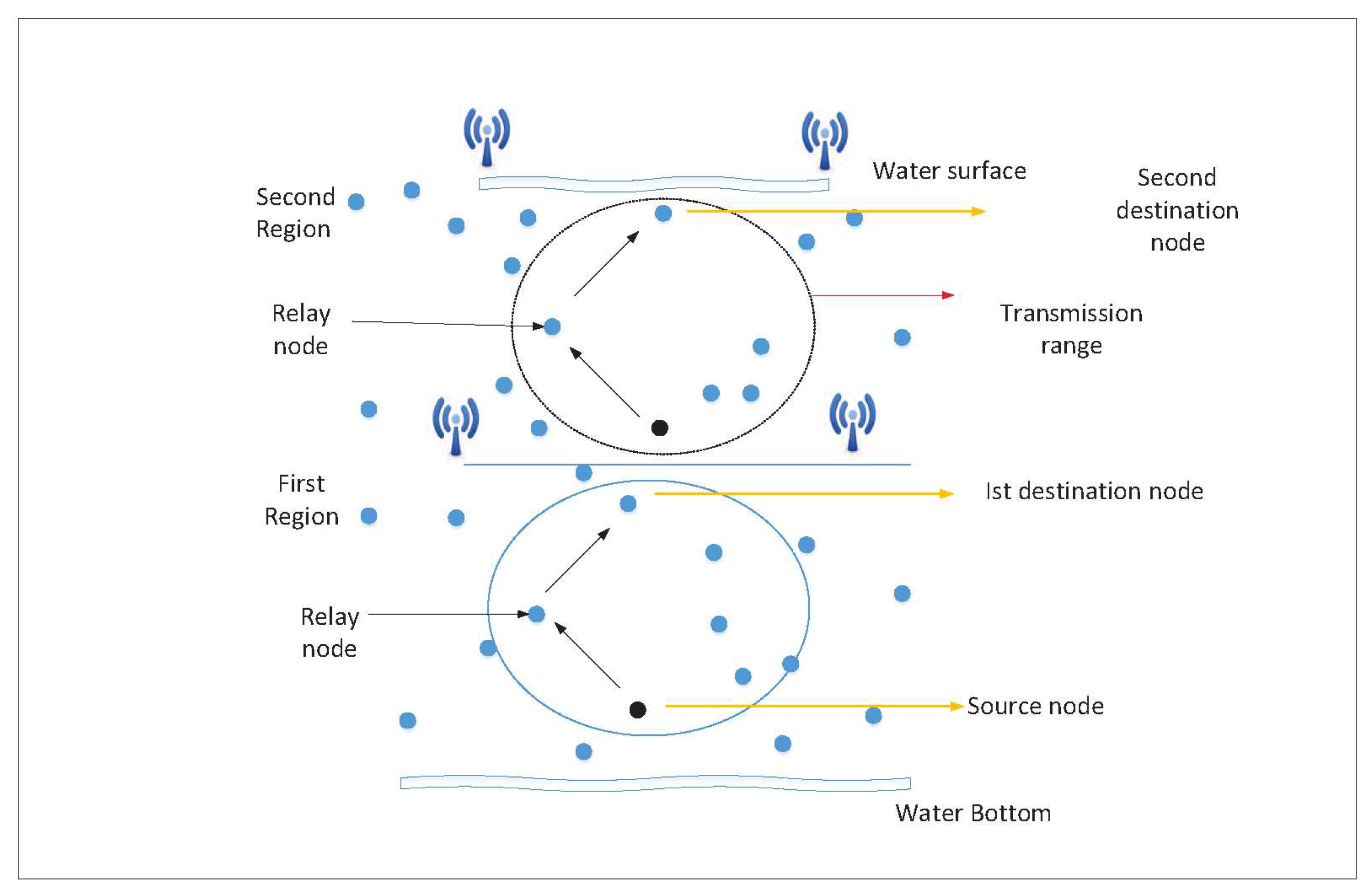
Network in space are of , consists of randomly deployed 200 nodes. Each nodes having finite amount of energy. The network is divided into two equal regions. Two super SNs are located at upper surface of the network, while two sub SNs are placed in the middle region of the network. The upper region in the network is called destination region, as it is near the sink while sensor nodes in this region are called DesNs. Nodes that are lying in the lowest depth are called source nodes. These nodes have ability to transmit data packets towards destination. Moreover, SNs are placed in such a way that the two super SNs are placed above the surface of network and two sub SNs are available in the middle of the network as shown in Figure 1. The design of this deployment refers to collect the data packets from all nodes. SNs in the network are equipped with both acoustic and radio modes at a time. However, SNs exchange data packets with each other through acoustic waves. SNs in the network are equipped with both acoustic and radio modes at a time. However, sensor nodes exchange data packets with each other through acoustic waves.The absorption rate of radio wave is higher than acoustic wave in underwater therefore, in under water the node communicate trough acoustic waves. The SN at upper region of network uses radio waves for exchange of information with onshore data center.
3.2. Hello Packet Forwarding and Neighbor Identification
Nodes are placed in under water in a random manner . After node deployment, sensor nodes are unfamiliar about their neighbors’ depth, shortest distance from source to destination and BER. The format of hello message consists of sender ID, depth of sensor node, shortest distance from source to destination and BER. Initially, the nodes in underwater sensor network have no knowledge of their neighbor for routing. The lowest depth, shortest distance, and BER are necessary in proposed scheme. In order to get information of each sensor node a hello message is transmitted by the final DesN towards sensor nodes. The structure of hello packet is shown in Figure 2.The capacity of hello packet is assumed to be 8 bytes which is essential for the exchange of information among all the sensor nodes [23]. The presence of a particular ID of SN helps differentiate hello packet that it sends. However, only those nodes respond to hello packet which exist within transmission range. Every node in the network gain information of its nearby node due to the broadcast nature of hello packet. The information of depth, shortest distance and BER of nodes are essential for the selection of best forwarder node. This process continues until all the nodes share their information among one another. To determine the BER, a node sends test packet to all neighbors. The test packet carry specific number of bits. This arrangement of bits is by default known to all the nodes. Whenever a test packet is received, every node in the network checks the amount of corrupted bits in a test packet due to channel behavior. Each node in the network then informs all the sensor nodes about the presence of corrupted bits in test packets.
3.3. Data Forwarding
In data forwarding section the source node chooses a forwarding node based on the depth of sensor node, shortest distance from source to DesN and BER. At first the source node investigates the best DesN on the basis of parameters lowest depth, shortest distance from source to destination and BER in the group of neighbor nodes. Whenever BER of DesN is high, the packet is dropped. Similarly another DesN is selected using the same parameters within the transmission range. This process of selection of DesN is continued until data has reached to SNs as shown in Figure 3. The selected DesN forwards the information packets to the next DesN by multi-hopping till data packet is received by final DesN. Whenever final DesN lies within the transmission range of source node then it directly sends information towards the final DesN. The weighting or cost function that is used for selection of best forwarder node among all the neighbors is written as:
Whenever the BER threshold value is less than , the packet is gain and directed towards next suitable node. But if the BER of the information packet is higher than the DesN drops the packet. If the information packet received at the DesN satisfy the BER threshold value, then it is accepted by DesN and forwarded to final DesN.
3.4. Cooperative routing protocol
We proposed a cooperative routing protocol with addition to DRAR protocol called as CO-DRAR. This routing protocol ensures reliability in transfer of valuable information through a channel with successful relaying between source and DesN. The mechanism of CO-DRAR is further explained as under:
In Co-DRAR protocol, data packet is forwarded towards final DesN in two different ways i.e direct path transfer and relay or cooperative path transfer as illustrated in Figure 5. In direct communication, when a source node is within the communication range of SN, it sends data packet directly towards the SN. However, if the SN is far away from the communication range of source node then cooperative routing is adopted which make DRAR as Co-DRAR. In order to achieve reliable data packets during transmission, source node in Co-DRAR select the DesN from neighbor nodes which lying near to the SN. A node posses shortest distance with respect to SN as taken as DesN. A node having second nearest distance to the SN is considers as relay node. Similarly source node broadcasts its data packet to destination and relay node respectively. Since BER of information packets is checked by DesN, if BER of the packet is lower than specified threshold, it will forward information directly to SN. But, if BER become maximum then its threshold, then a request is send to a relay node to send same information again. After this, relay forwards its information together with acknowledgment to DesN. The data packets from both source and relay node are recombine at each DesN using Fixed Ratio Combined (FRC). This technique is preferred instead of Maximal Ratio Combine (MRC) technique that required complete channel information which is challenging task in underwater.
Finally the information is merged together at destination point, these information further evaluated to extract desired valuable information. Next the information is forwarded from destination point to SNs located at both regions of the network. Finally the information is broadcasted from lower region to upper region SNs of the network. The flow chart of our both protocols as shown in Figure 4.
Figure 4.
Flow Chart of the Proposed Protocol.
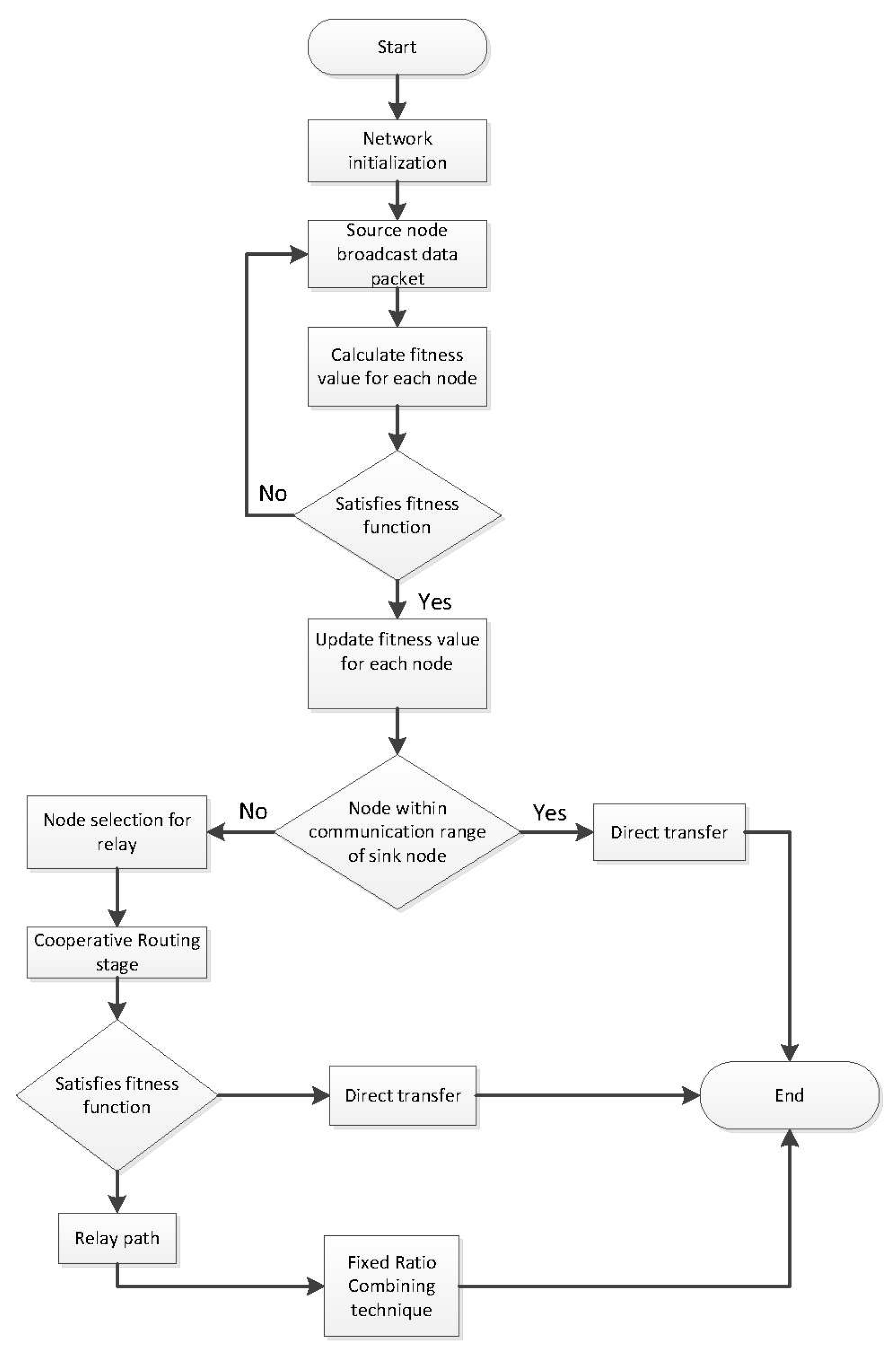
Figure 5.
Co-DRAR Scheme.
4. Simulation Results
In this section we compare the simulations results of both DRAR and Co-DRAR protocols with existing DBR [24] protocol. The simulations are performed using Matlab simulator. The network contains 200 nodes distributed randomly in area having length, width and height of , respectively. Two super SNs are placed at upper region of the network, while two sub SNs are fixed at mid region of the network. In proposed protocol the depth threshold for all the nodes in the network remain fixed. A protocol known as Medium Access Control (MAC) is used in the proposed scheme [12]. In MAC, the nodes first check and identify the condition of channel, through which data is to be forwarded. If channel is free then they start broadcasting. Or if channel is busy then the nodes wait. But if channel is not vacant up to a specific time, then the data is dropped. The SNs in both regions of the network are positioned at stationery mode. The sensor nodes can move easily from one position to another position with no restriction due to water flow. Due to water currents, the speed of sensor nodes nearly reach up-to [13]. The nodes in the network use the acoustic modem of LinkQuest UWM 1000 in order to communicate with each other. Transmission range of each node in the network is assumed 100m in all directions and consume power of 0.1w, 2w and 10mW power for receive, transmit and idle state, respectively. Initially, the nodes carry energy of 10J and the packet size of each sensor is 50 bytes with 10 kbps data rate. The parameter of network for simulation depicted in Table 1.
4.1. Packet Delivery Ratio
The comparison of proposed protocols and the DBR in term of PDR is depicted in Figure 6. The Co-DRAR out performance compared to the rest of protocols because PDR of Co-DRAR protocol is cooperation of single relay node and putting SN at both region of the network. In case of Co-DRAR scheme every sensor node in the network forwards its information to the desired SN and as a result more number of data packet reached successfully. This mechanism increases the PDR of proposed scheme. Similarly that nodes which lie near to the SNs in both regions of the network send their information directly. While that node which situate for away from the SN forwards its valuable information through single relay node using method of cooperation. Due to this mechanism the packet drop ratio decreases as compared to DBR scheme and gain the highest PDR. Also the PDR of DBR scheme is well better than DRAR, because DRAR scheme show better result on lowest depth node faced by DBR scheme. The PDR value of Co-DRAR scheme start from value 1 because of cooperation, while the value of DRAR and DBR scheme start from due to non-cooperation while the presence of cooperation in scheme brings the reliability in forwarding the information. The long transmission path degraded PDR of DBR scheme as compared to DRAR scheme.
4.2. End-to-End Delay
The E2E delay of proposed protocol is shown in Figure 7. The proposed protocol have less latency because the absence of cooperation in data transmission. The delay of DBR scheme is more than DRAR and Co-DRAR because in DBR protocol, the source node which forward the information packet from highest depth to lowest depth DesN. Similarly DBR protocol follows the long transmission path which utilize more time to reach the data packet to desired DesN. In case of Co-DRAR protocol, presence of single relay node and positioned of SN at both region of the network decrease the path length which in turn reduces the delay during transmission of data packet. As in both region of the network the sensor nodes situate near to SN send their data packets directly to SN. However, node far away from the SN forwarded their data packet to desired destination through cooperation using the single relay and considering less physical distance. This mechanism decreases the transmission path and reduce the delay.
4.3. Packet Received at Sink
The Figure 8 shows the number of packets reached successfully to final DesN. The ratio of packet received by the SN of DRAR is better then DBR, further Co-DRAR achieves better performance then DRAR and DBR. The reason of this high number of packet received at SN in Co-DRAR scheme is due to reason of cost function parameters i.e highest RE, lowest BER and shortest distance. The cost function ensures the maximum number of packet reached to the final DesN. The Co-DRAR scheme using the single relay node during cooperation with DesN. The contribution of more number of nodes in Co-DRAR scheme utilize maximum energy and those nodes that lie near to the surface die quickly due to that data loss occurred.
4.4. Total Energy Consumption
The Figure 9 shows the comparison of three protocols in term of total EC. The EC of Co-DRAR and DRAR protocols is less than DBR protocol. Low consumption of energy in Co-DRAR protocol is due to the cooperation technique. Consequently, nodes away from the SN in both region of the network forward their information in cooperative manner. Moreover, Co-DRAR protocol uses SNs in both region of the network that help to reduce the congestion of data packet due to long multi-path routing. Secondly the EC of DRAR protocol is less than DBR scheme. This is because of the balance EC in the network which permit the nodes to transmit more number of information at rate of minimum energy cost. In case of DBR protocol more energy is consumed in transmission of packet from highest depth source node towards the sink which in turn increases the energy consumption.
4.5. Dead Nodes
The number of dead node is lower in DRAR and Co-DRAR protocol as shown in Figure 10. The DRAR protocol possess minimum number of DN than Co-DRAR and DBR protocols. In Co-DRAR protocol, cooperation is performed by selecting only one DesN to forward information towards the final destination. Co-DRAR has less number of dead node because it consumes less energy than DBR scheme.
4.6. Alive Nodes
The Figure 11 shows the number of ANs in all protocols. The rate of AN in DRAR protocol is higher in comparison with Co-DRAR and DBR protocols. In DRAR protocol, only one DesN can transmit the data packets towards the final DesN. Due to this reason minimum energy is consumed and there are more number of ANs. The Co-DRAR protocol has maximum number of ANs than DBR protocol. This is due Co-DRAR protocol only one destination and relay node are contributed to transfer the information towards the desired nodes. As DBR consume more energy due to multi-hopping and possess less number of ANs.
4.7. Number of Packet Drops
Figure 12 shows the comparison of our proposed protocol DRAR and CO-DRAR with DBR in terms of packet drop ratio. In CO-DRAR less number of information packets is drooped, more packets reached successfully to final DesN due to cooperation involved in CO-DRAR. The packet drop ratio is comparative high in DRAR while, DBR depicts more number of packets drop as compared to DRAR and CO-DRAR scheme.
5. Conclusion
We propose two routing protocols known as (DRAR) protocol and Cooperative Delay (Co-DRAR) protocol for UWSNs. In DRAR protocol the network is divided into two equal regions to reduce delay. Two super SN are located at upper surface of the network while two sub SN are placed in the middle region of the network. The proposed frame work is used to ensure low EC in order to reliably forward data packets towards SNs. The Co-DRAR scheme ensure the reliability in transfer of valuable information through a channel with successful relying between source and DesN. Due to network division in two regions data load is reduced and EC of sensor nodes decreases. In Co-DRAR, the sensor nodes in both regions of the network send their data packet directly towards SN. In proposed Co-DRAR frame work, the best forwarder node is chose using the value of cost function i.e. lowest depth, shortest distance and BER. The lowest depth and shortest distance make sure that data packet reached successfully to the final destination. The protocols shows improved performance in term of EC, PDR, ANs, PDR, total number of packets drop and total number of packet received successfully to SN.

Table 2.
Tale of Abbreviations.
| Keyword | Expanded form |
|---|---|
| PDR | Packet delivery ratio |
| BET | Bit error rate |
| E2E | End-to-end delay |
| RE | Residual energy |
| DBR | Depth base routing |
| SNs | Sink nodes |
| SN | Sink node |
| MRC | Maimal ratio combine |
| MAC | Medium access control |
| UWSNs | Underwater wireless sensor networks |
| EC | Energy consumption |
| AN | Alive Node |
| ANs | Alive Nodes |
| DesN | Destination Node |
| DesNs | Destination Nodes |
Author Contributions
Conceptualization, A.S., S.M. and N.H.; methodology, A.S, S.U. and N.H.; software, A.S, S.U. and N.H.; validation, S.M., N.H. and J.S.; formal analysis, N.H., S.M. and J.S.; investigation, S.U. and N.H.; resources, J.S.; data curation, A.M., S.U. and N.H.; writing—original draft preparation, A.M., S.U. and N.H.; writing—review and editing, A.M., S.U., N.H., J.S. and A.L.; visualization, S.M and N.H.; supervision, S.M. N.H.; project administration, N.H. and J.S.; funding acquisition, J.S. All authors have read and agreed to the published version of the manuscript.
Funding
This work was supported by the Competitive Research Fund of The University of Aizu, Japan.
Institutional Review Board Statement
None.
Informed Consent Statement
None.
Data Availability Statement
None.
Conflicts of Interest
The authors declare no conflict of interest.
References
- Ayaz, M.; Abdullah, A. Underwater wireless sensor networks: routing issues and future challenges. Proceedings of the 7th international conference on advances in mobile computing and multimedia. ACM, 2009, pp. 370–375.
- Ullah, U.; Khan, A.; Altowaijri, S.M.; Ali, I.; Rahman, A.U.; Kumar, V.; Ali, M.; Mahmood, H.; others. Cooperative and delay minimization routing schemes for dense underwater wireless sensor networks. Symmetry 2019, 11, 195. [Google Scholar] [CrossRef]
- Javaid, N.; Jafri, M.R.; Khan, Z.A.; Qasim, U.; Alghamdi, T.A.; Ali, M. Iamctd: Improved adaptive mobility of courier nodes in threshold-optimized dbr protocol for underwater wireless sensor networks. International Journal of Distributed Sensor Networks 2014, 10, 213012. [Google Scholar] [CrossRef]
- Proakis, J.G.; Sozer, E.M.; Rice, J.A.; Stojanovic, M. Shallow water acoustic networks. IEEE communications magazine 2001, 39, 114–119. [Google Scholar] [CrossRef]
- Felemban, E.; Shaikh, F.K.; Qureshi, U.M.; Sheikh, A.A.; Qaisar, S.B. Underwater sensor network applications: A comprehensive survey. International Journal of Distributed Sensor Networks 2015, 11, 896832. [Google Scholar] [CrossRef]
- Noh, Y.; Wang, P.; Lee, U.; Torres, D.; Gerla, M. DOTS: A propagation delay-aware opportunistic MAC protocol for underwater sensor networks. The 18th IEEE International Conference on Network Protocols. IEEE, 2010, pp. 183–192.
- Pompili, D.; Melodia, T.; Akyildiz, I.F. Routing algorithms for delay-insensitive and delay-sensitive applications in underwater sensor networks. Proceedings of the 12th annual international conference on Mobile computing and networking. ACM, 2006, pp. 298–309.
- Basagni, S.; Petrioli, C.; Petroccia, R.; Spaccini, D. CARP: A channel-aware routing protocol for underwater acoustic wireless networks. Ad Hoc Networks 2015, 34, 92–104. [Google Scholar] [CrossRef]
- Javaid, N.; Jafri, M.R.; Ahmed, S.; Jamil, M.; Khan, Z.A.; Qasim, U.; Al-Saleh, S.S. Delay-sensitive routing schemes for underwater acoustic sensor networks. International Journal of Distributed Sensor Networks 2015, 11, 532676. [Google Scholar] [CrossRef]
- Umar, A.; Akbar, M.; Iqbal, Z.; Khan, Z.A.; Qasim, U.; Javaid, N. Cooperative partner nodes selection criteria for cooperative routing in underwater WSNs. 2015 5th National Symposium on Information Technology: Towards New Smart World (NSITNSW). IEEE, 2015, pp. 1–7.
- Nasir, H.; Javaid, N.; Ashraf, H.; Manzoor, S.; Khan, Z.A.; Qasim, U.; Sher, M. CoDBR: cooperative depth based routing for underwater wireless sensor networks. 2014 Ninth International Conference on Broadband and Wireless Computing, Communication and Applications. IEEE, 2014, pp. 52–57.
- Khan, A.; Javaid, N.; Mahmood, H.; Khan, Z.A.; Qasim, U. ; others. EEIRA: An energy efficient interference and route aware protocol for underwater WSNs. Complex, Intelligent, and Software Intensive Systems (CISIS), 2016 10th International Conference on. IEEE, 2016, pp. 264–270.
- Qadar, J.; Khan, A.; Mahmood, H. DNAR: Depth and Noise Aware Routing for Underwater Wireless Sensor Networks. Conference on Complex, Intelligent, and Software Intensive Systems. Springer, 2018, pp. 240–251.
- Khan, A.; Javaid, N.; Ali, I.; Anisi, M.H.; Rahman, A.U.; Bhatti, N.; Zia, M.; Mahmood, H. An energy efficient interference-aware routing protocol for underwater WSNs. KSII Transactions on Internet and Information Systems 2017, 11, 4844–4864. [Google Scholar]
- Chao, C.M.; Jiang, C.H.; Li, W.C. DRP: An energy-efficient routing protocol for underwater sensor networks. International Journal of Communication Systems 2017, 30, e3303. [Google Scholar] [CrossRef]
- Bu, R.; Wang, S.; Wang, H. Fuzzy logic vector–based forwarding routing protocol for underwater acoustic sensor networks. Transactions on Emerging Telecommunications Technologies 2018, 29, e3252. [Google Scholar] [CrossRef]
- Isufi, E.; Dol, H.; Leus, G. Advanced flooding-based routing protocols for underwater sensor networks. EURASIP Journal on Advances in Signal Processing 2016, 2016, 52. [Google Scholar] [CrossRef]
- Khan, A.; Ali, I.; Rahman, A.U.; Imran, M.; Mahmood, H.; others. Co-EEORS: Cooperative Energy Efficient Optimal Relay Selection Protocol for Underwater Wireless Sensor Networks. IEEE Access 2018. [Google Scholar] [CrossRef]
- Shah, S.; Khan, A.; Ali, I.; Ko, K.M.; Mahmood, H. Localization Free Energy Efficient and Cooperative Routing Protocols for Underwater Wireless Sensor Networks. Symmetry 2018, 10, 498. [Google Scholar] [CrossRef]
- Javaid, N.; Hussain, S.; Ahmad, A.; Imran, M.; Khan, A.; Guizani, M. Region based cooperative routing in underwater wireless sensor networks. Journal of Network and Computer Applications 2017, 92, 31–41. [Google Scholar] [CrossRef]
- Lilhore, U.K.; Khalaf, O.I.; Simaiya, S.; Tavera Romero, C.A.; Abdulsahib, G.M.; Kumar, D. A depth-controlled and energy-efficient routing protocol for underwater wireless sensor networks. International Journal of Distributed Sensor Networks 2022, 18, 15501329221117118. [Google Scholar] [CrossRef]
- Xiao, X.; Huang, H. A clustering routing algorithm based on improved ant colony optimization algorithms for underwater wireless sensor networks. Algorithms 2020, 13, 250. [Google Scholar] [CrossRef]
- Majid, A.; Azam, I.; Waheed, A.; Zain-ul Abidin, M.; Hafeez, T.; Khan, Z.A.; Qasim, U.; Javaid, N. An energy efficient and balanced energy consumption cluster based routing protocol for underwater wireless sensor networks. 2016 IEEE 30th International Conference on Advanced Information Networking and Applications (AINA). IEEE, 2016, pp. 324–333.
- Yan, H.; Shi, Z.J.; Cui, J.H. DBR: depth-based routing for underwater sensor networks. International conference on research in networking. Springer, 2008, pp. 72–86.
Figure 1.
Network Model.
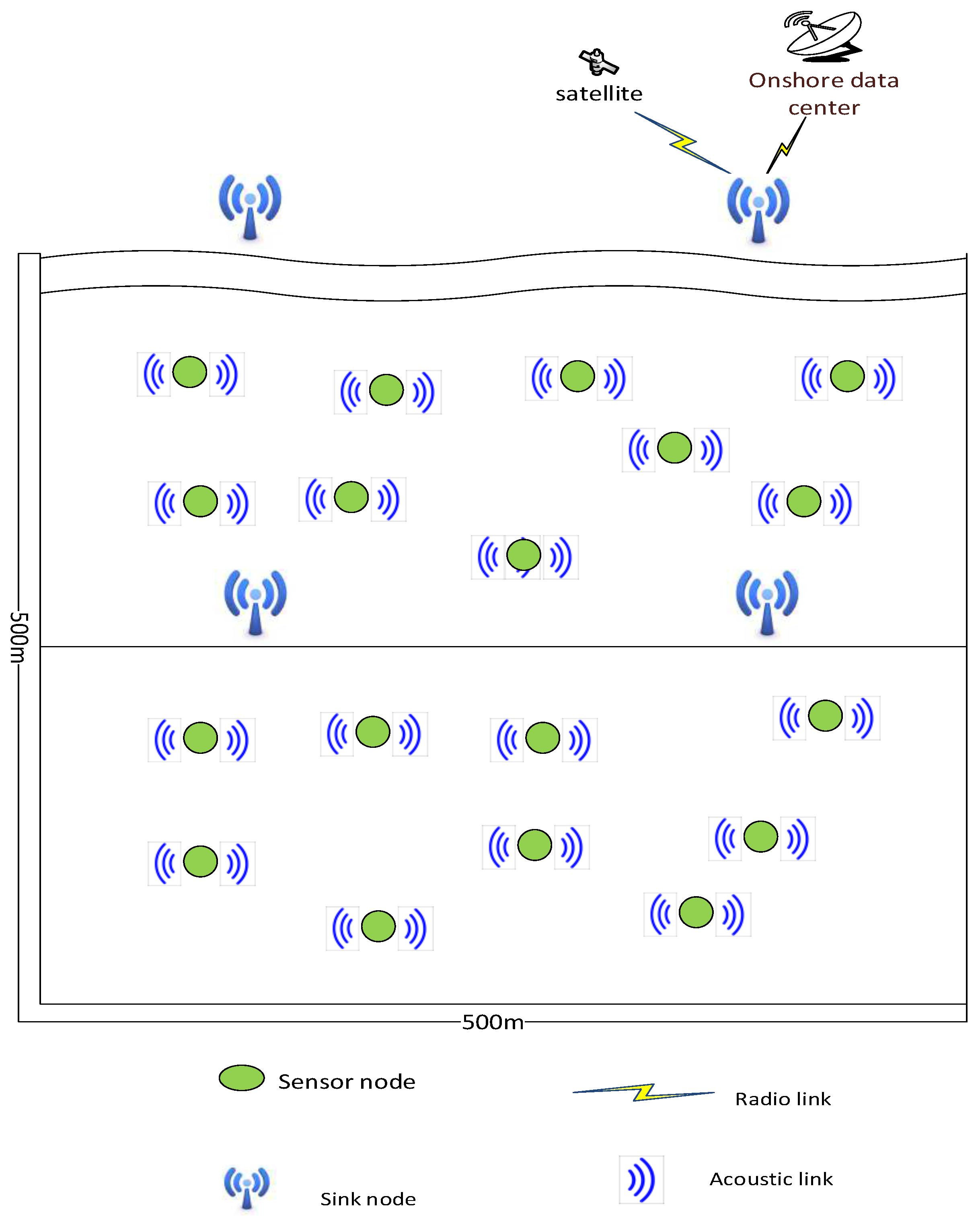
Figure 2.
Hello packet information
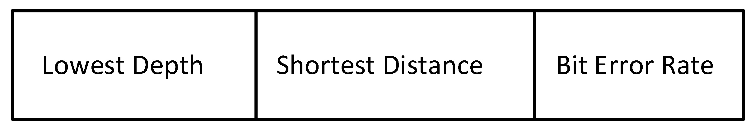
Figure 3.
Data forwarding using best destination node in both regions of network.
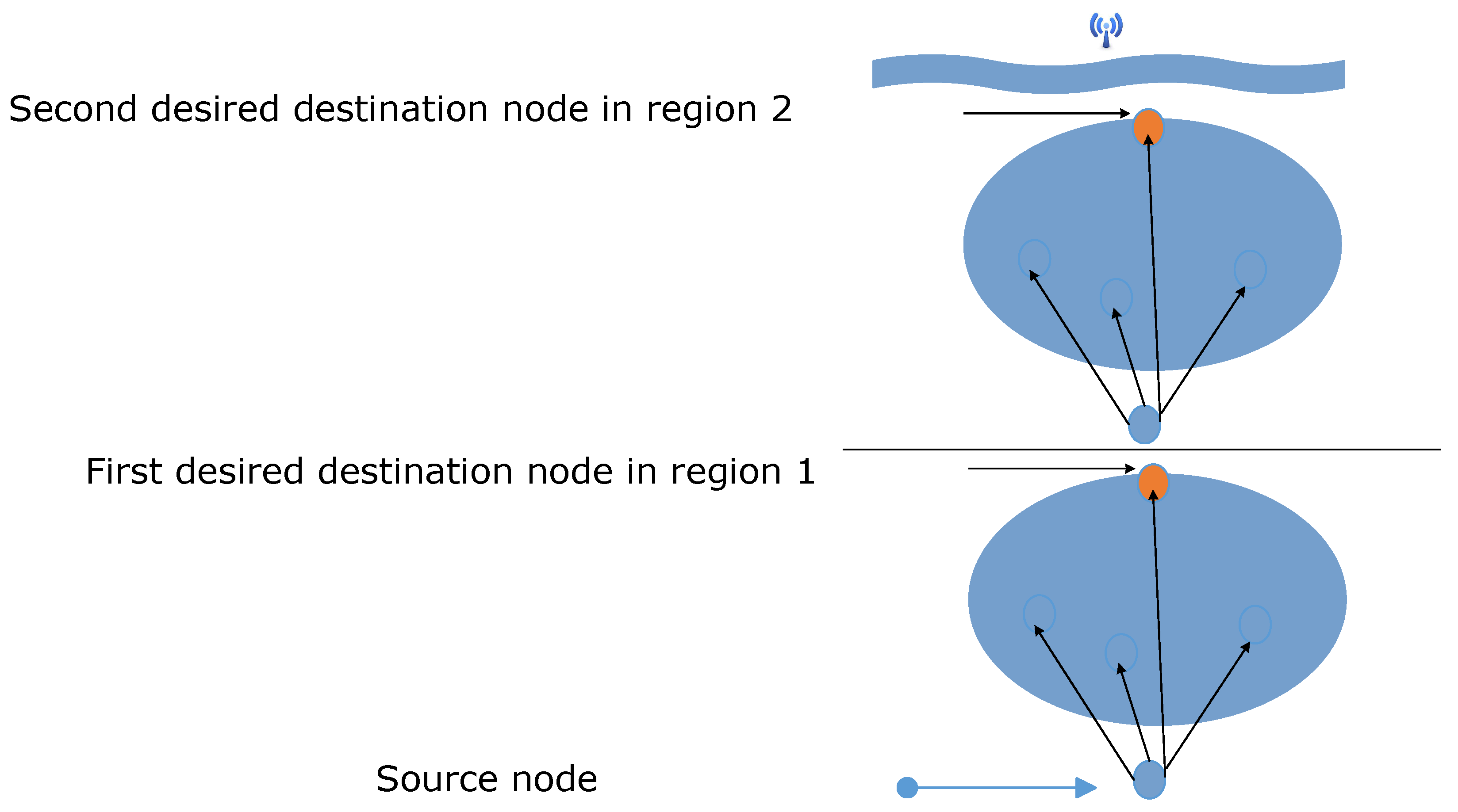
Figure 6.
Packet Delivery Ratio.
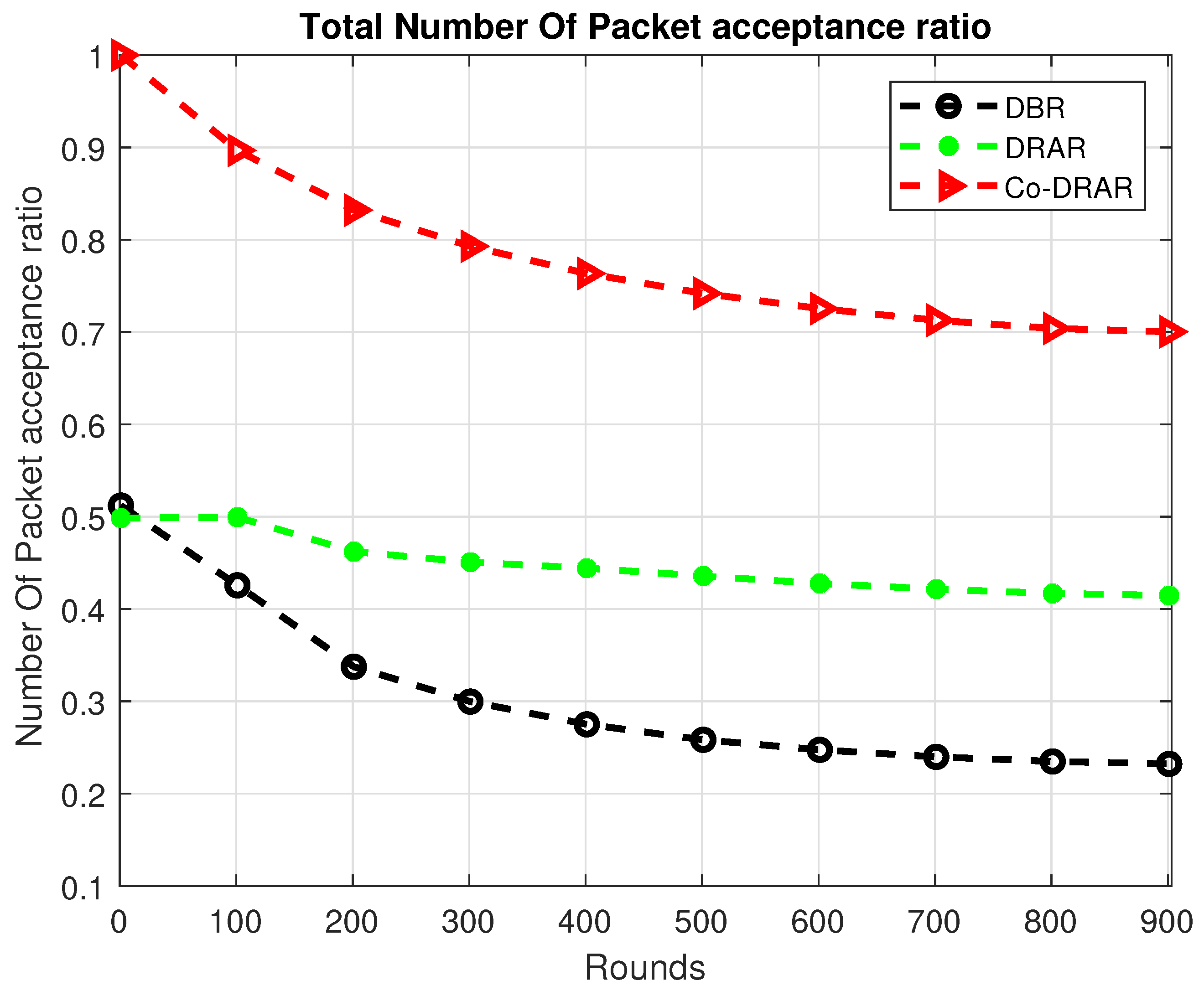
Figure 7.
End-to-End Delay.
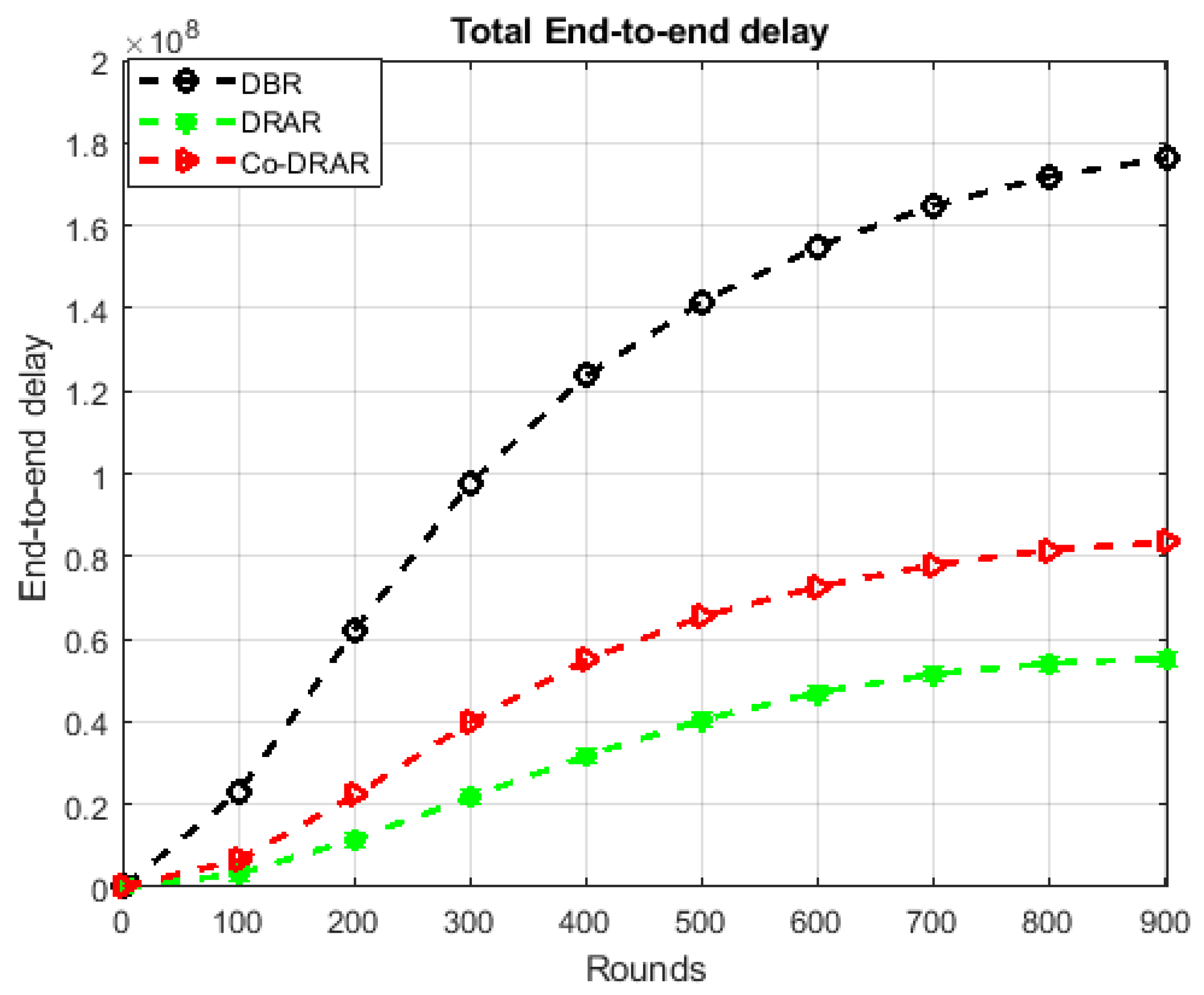
Figure 8.
Packet Received.
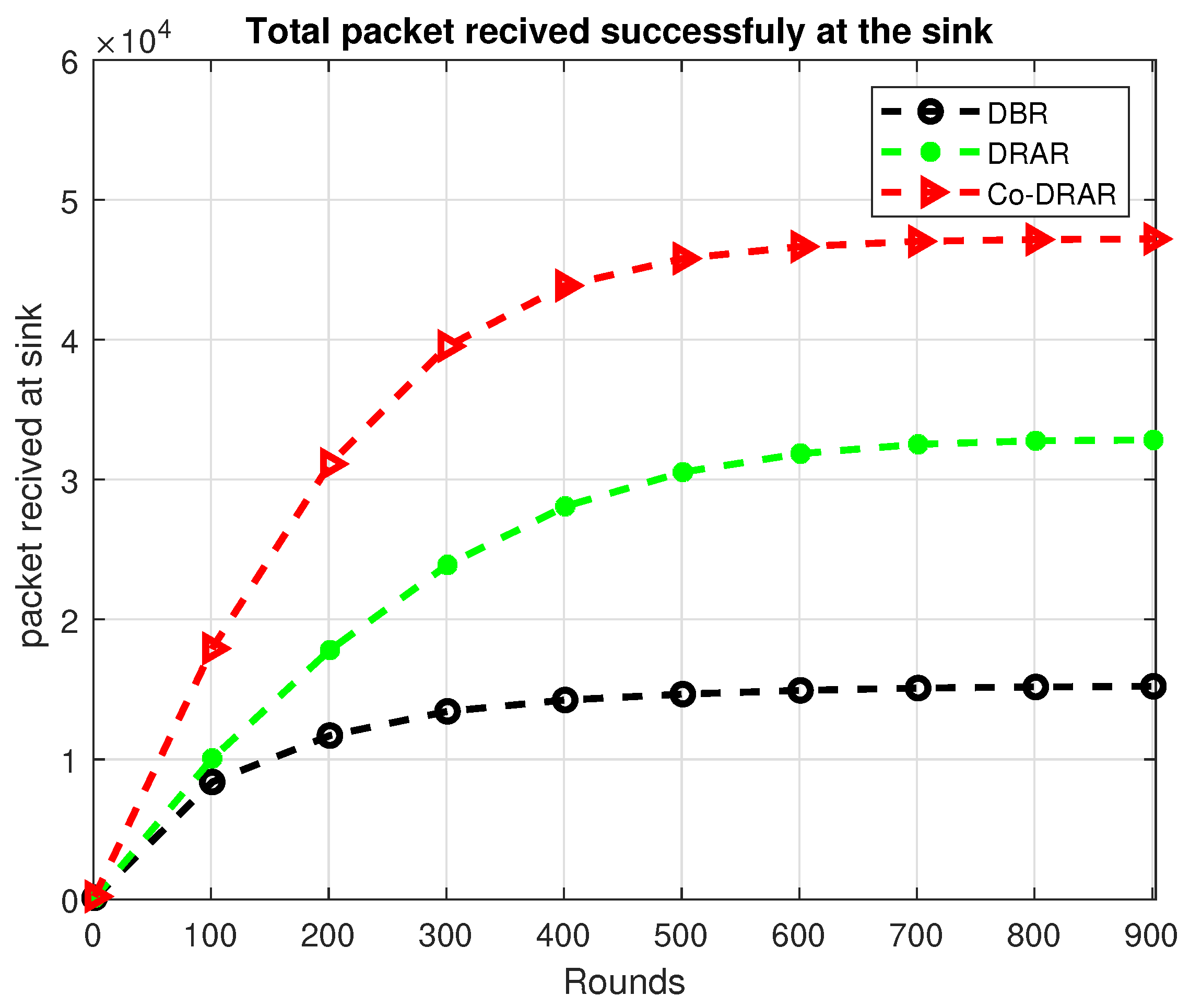
Figure 9.
Total Energy Consumption.
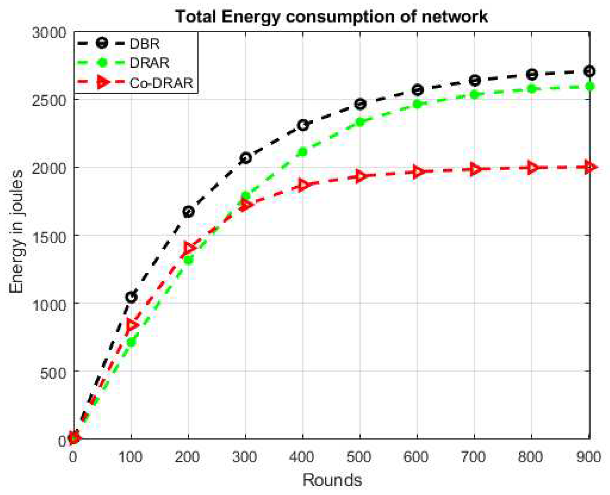
Figure 10.
Total Number of Dead Node.
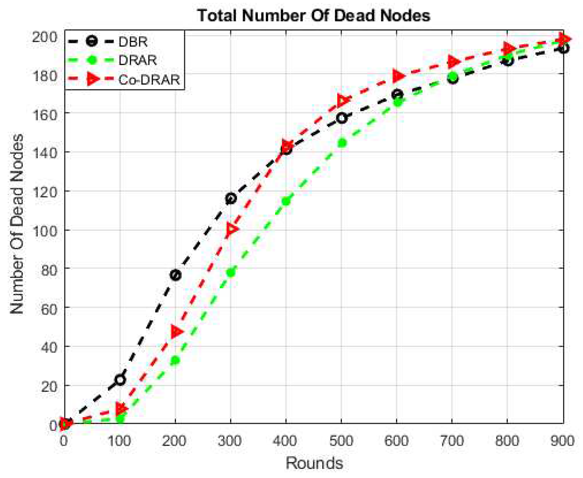
Figure 11.
Total Number of Alive Node.
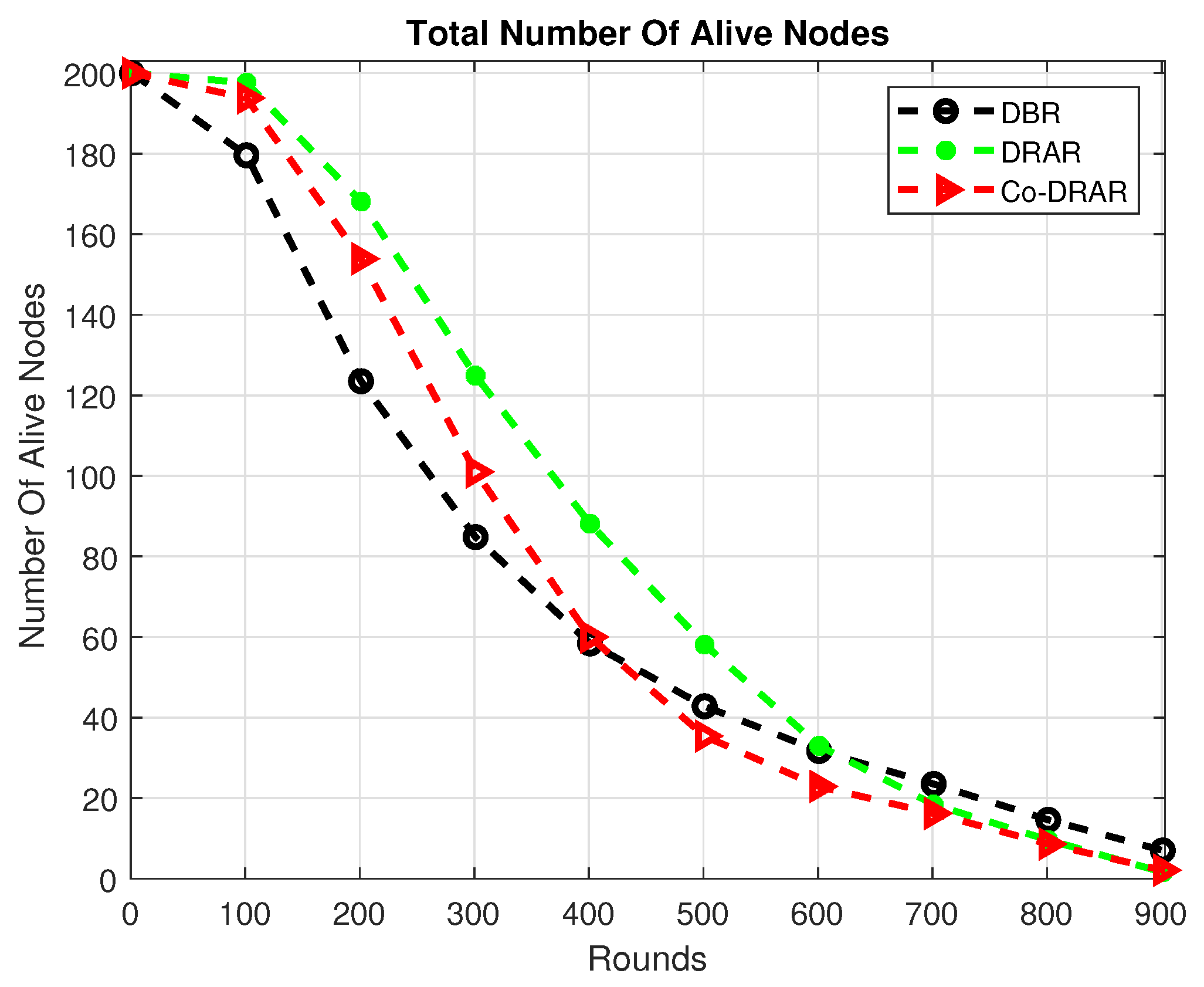
Figure 12.
Number of Packet Drops.
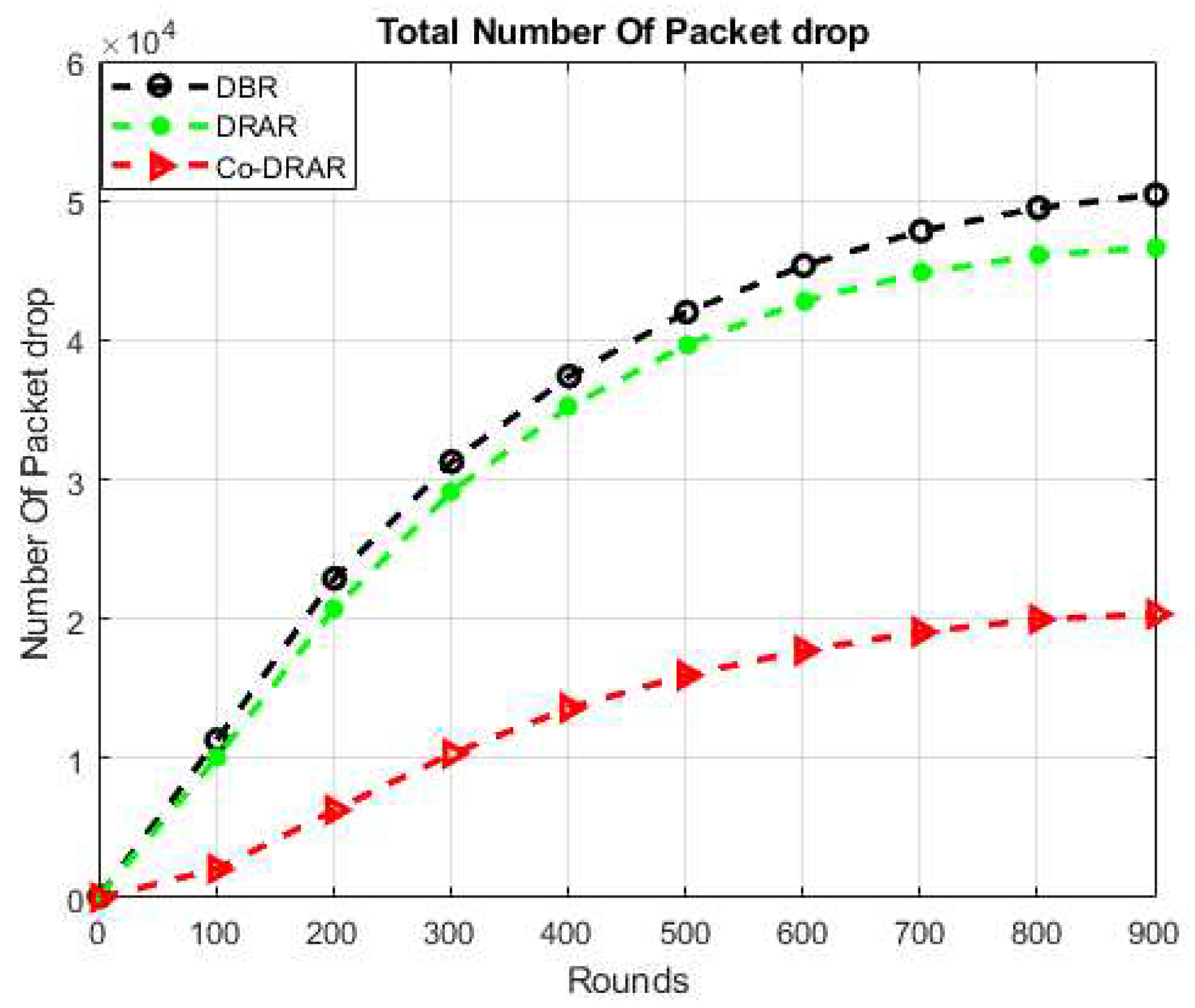
Table 1.
Parameters for Simulation.
| Operations | Values |
|---|---|
| Network height | 500m |
| Network depth | 500m |
| Network width | 500m |
| Initial energy | 10J |
| Frequency | 30KHz |
| Packet size | 50 bytes |
| Transmission range | 100m |
| Bandwidth | 30KHz |
| Sensor nodes | 200 |
| Depth threshold | 60m |
| Sink nodes | 4 |
Disclaimer/Publisher’s Note: The statements, opinions and data contained in all publications are solely those of the individual author(s) and contributor(s) and not of MDPI and/or the editor(s). MDPI and/or the editor(s) disclaim responsibility for any injury to people or property resulting from any ideas, methods, instructions or products referred to in the content. |
© 2023 by the authors. Licensee MDPI, Basel, Switzerland. This article is an open access article distributed under the terms and conditions of the Creative Commons Attribution (CC BY) license (http://creativecommons.org/licenses/by/4.0/).
Copyright: This open access article is published under a Creative Commons CC BY 4.0 license, which permit the free download, distribution, and reuse, provided that the author and preprint are cited in any reuse.


