Submitted:
18 April 2023
Posted:
18 April 2023
You are already at the latest version
Abstract
The manuscript presents a unified methodology for the engineering design of resonant inverters used for power sources to power various technologies based on induction heating. The methodology is compiled using the generalized consideration of electromagnetic processes in a series RLC circuit and the quasi-boundary method for the analysis of resonant inverters with and without reverse diodes operating in soft and hard commutation modes. On this basis, the transmission functions of the inverters are derived, and the matching between the parameters of the inverter and the load through complicated output circuits is also considered. The basic ratios for determining the circuit elements and their current and voltage loading are presented. The methodologies are verified using several computational examples, simulations and measurements from induction heating devices. The simplified design approach presented is useful for its application in power electronics training and also in the design of various devices using the principle of induction heating. Another important result is the achievement of formalization and algorithmization of the design process, which is a consequence of the application of a unified approach both in the analysis and in the design of a whole class of power electronic devices.
Keywords:
unified approach to design
; design consideration
; resonant inverters
; induction heating applications
1. Introduction
Resonant converters of electrical energy have found a very widespread both in industry, transport, energy, medicine and in the home. They are distinguished by a number of advantages over other types of power electronic devices, the most important of which are: thanks to the very nature of electromagnetic processes, implementation of work with "soft" commutations; good regulation characteristics; possibility of operation in modes close to short circuit in the load; use of parasitic circuit elements as part of the resonant circuit; good energy, mass, size and economic indicators, etc. [1,2,3,4,5].
The commercialization of resonant converters and scientific research in this area in the last 50-60 years have been conditioned by the emergence, development and great variety of various industrial technologies such as: induction heating, melting, alloying, soldering, welding, and in recent years for the preparation of nanostructures and nanomaterials [5,6,7,8,9].
For some time, there has been a trend of using and transferring knowledge and experience from industrial technologies in systems for contactless transmission of electrical energy, as well as in the home: induction stoves and cooktops, induction boilers and heaters, implementation of high-efficiency lighting fixtures, etc. [10,11,12,13].
Another important factor that contributed to the rapid development of these technologies is the growing needs, which led to the increase in the standard of living of the Earth's population, which in turn necessitated the use of resonant converters in other areas of technology: decentralized production of electrical energy from renewable and alternative sources: electric transport; for charging stations for electric cars, in "smart" power grids, etc. [14,15,16,17,18].
Depending on the type of load, resonant converters of electrical energy are divided into two main types:
- for conversion of direct current into direct current energy - resonant DC-DC converters with direct current output;
- for conversion of direct current into alternating current energy - resonant converters with AC output (inverters).
Also, the diverse topologies, the different types of power semiconductor elements make it possible to implement a very large set of control algorithms and, accordingly, operating modes. In this aspect, there are numerous studies dedicated to the analysis, design and prototyping of a specific power electronic device, taking into account the specifics of its application. Static characteristics of resonant converters operating in resonance modes are presented in [19]. They were obtained by analyzing idealized series resonant circuit converters under various combinations of connected voltage sources. The proposed procedure allows obtaining expressions for calculating the steady-state current of the alternating current circuit. In [20] shows a high power resonant converter applied to power an induction furnace for steel melting. To reduce switching losses, zero voltage switching (ZVS) is achieved in the H-bridge converter. In [21] a new high-accuracy simulation design tool for DC-DC resonant converters is proposed. The design tool uses generalized time domain analysis applicable to multiple resonant converter configurations. A performance analysis of a new resonant converter circuit configuration using a sinusoidal approximation is shown in [22]. A 250 W prototype of the proposed resonant converter was built to verify the analysis proposed in this paper and evaluate its performance. In [23], the analysis and design of a current source fed parallel resonant (CFPP-PR) converter for cooker magnetrons is given. To demonstrate the analysis and design, a resonant converter was built and tested. The simulation and experiment results match those obtained from the analysis. Fundamental frequency analysis is also used to analyze the steady-state operation of the three most popular resonant load converters when operating with a limited frequency range [24]. The developed equations that describe the electromagnetic processes make it possible to determine the circuit elements. The validity of the proposed design ratios and the identified optimal operating conditions are confirmed by time-domain simulations and measurements on a series-parallel resonant converter prototype. Another way to analyze and design resonant converters containing a large number of reactive elements is model reduction [25]. It is known that the complex equivalent circuit (of high order) in the small-signal modeling of the resonant converter is a barrier to the derivation of analytical dependencies and the physical interpretation of the processes in the power circuit. This paper investigates the order reduction and approximation of the equivalent circuit of the series resonant converter (SRC). It is shown that there is a close interaction between the resonant inductor branch and the resonant capacitor branch that must be accounted for when making an approximation. Using this methodology, a simplified third-order SRC equivalent circuit is proposed. It corrects the phase deviation problem of the reduced-order model when the switching frequency is close to the resonant frequency. The validity of the proposed equivalent scheme is confirmed by the results of numerical experiments.
From the analysis of numerous publications on this topic, it follows that there is a lack of up-to-date research that addresses the methodological aspect in the study of power electronic devices and systems and where engineering design methodologies are presented and discussed.
The aim of this work is to present a rational methodology for the engineering design of a whole class of power electronic devices - resonant DC/AC converters for powering induction technologies. In this sense, the main tool for achieving this goal is the unified approach presented by the author for the analysis of DC/AC converters, based on the study of electromagnetic processes in a series RLC circuit [26]. The manuscript is organized as follows: the first chapter describes the basic concepts and applications of resonant inverters. Various analysis and design approaches are considered; The second chapter is devoted to the methodological basis of the unified approach for the design of resonant inverters with electrotechnological application; In the third chapter, transmission characteristics of resonant inverters with and without reverse diodes operating in modes with soft and hard commutation of the semiconductor bars are determined; In the fourth chapter, the most frequently applied complicated output circuits are analyzed, through which the agreement between the parameters of the inverter and the load is carried out; In the fifth chapter, the unified methodologies for the design of parallel and series resonant inverters with and without reverse diodes are presented; In the sixth chapter, calculation examples are presented, through which the unified design methodologies were verified; Chapter 6 provides discussion and conclusion.
2. Methodological basis of the unified design approach
Regardless of the great variety of induction electrotechnologies, from the point of view of electrical engineering, they are most often presented with a series substitution circuit composed of an active load R and a reactive load ωL. Thus, the loads for the power electronic devices that provide the high-frequency energy are active-inductive loads with a very low power factor cosφT [27,28,29,30]. On the other hand, due to the requirement to obtain a certain active power, it is necessary to compensate these loads with capacitors. Depending on the way the capacitors are connected to the load, parallel and series compensation and a series or parallel load resonant circuit are obtained, respectively. From the point of view of physical implementation of induction heating devices, parallel compensation is mainly used. [27,30] Figure 1 shows basic schemes of resonant inverters with electrotechnological application, using parallel (Figure 1a and Figure 1b) and series compensation (Figure 1c and Figure 1d).
Due to the properties of semiconductor elements, thyristor circuits (Figure 1a, b, and c) are without reverse diodes, while transistor circuits (Figure 1d) are with reverse diodes. On the other hand, in circuits without reverse diodes, it is possible to divide the resonant inductance into two parts (Figure 1b and c), which achieves different levels of voltage loading on the thyristors [29].
Due to the specificity of the load, the quality factor of the parallel resonant load circuit has typical values in the range Q=3÷30. In this case, the load circuit acts as a filter for the higher current harmonics in the AC circuit of the inverter. In this way, the influence of all current harmonics in the AC circuit without the first can be neglected on the load [28,30]. Then, for analysis and design purposes, the parallel resonant load circuit is replaced by series-connected active R(1) and reactive X(1) resistances at the first harmonic of the current in the AC circuit. These ingredients are defined by the expressions [30]:
where Re is the active resistance from the parallel replacement circuit of the series RL load and γ is the angle between the current in the inverter AC circuit and the load voltage.
In a number of cases, the series compensation is also used, where a compensating capacitor is connected in series with the active-inductive load. This type of compensation became of greater practical importance in connection with the application of the material "Fluxtrol" [31], which, based on the concentration of the electromagnetic field in the inductor, significantly improves cosφΤ of the load. In induction technologies, the loads are low-impedance and thus a series resonant circuit is obtained in the series compensation in a natural way. In this sense, when powering electrothermal devices, regardless of the type of compensation, the alternating current circuit of the resonant inverter, which can be of arbitrary complexity, is represented equivalently by the first harmonic of the control frequency with a series RLC circuit. The equivalent circuit corresponding to these considerations is shown in Figure 2.
In this context, the following values of the elements of the generalized serial equivalent scheme are valid for the various circuit variants:
- In series compensation, R is the active component of the load, CR is the resonant capacitor, and the resonant inductance LR can be composed entirely of the inductive component of the load L or added as an additional inductance to the resonant one - LK;
- In parallel compensation, the active resistance in the circuit R=R(1) is the equivalent active resistance at the first harmonic of the control frequency of the parallel load circuit, the resonant capacitor CR=C(1) is the equivalent reactance at the first harmonic of the control frequency of the parallel load circuit, and the resonant inductance LR can be entirely in the inverter DC circuit, entirely in the inverter AC circuit, or divided in any ratio between them.
When using complex resonant output circuits to match the parameters of the inverter and the load, again the equivalent circuit of Figure 2 is valid, but the relevant parameters of the series RLC circuit are determined by a more complicated procedure, which is described in the following sections of the manuscript. On the other hand, in some of the schematic varieties of resonant inverters, the role of resonant elements can also be performed by the detuned parallel resonant load circuit when a parallel compensated load is used.
From the review of the basic topologies used for the implementation of various electrotechnological processes, it was established that the unified approach for the analysis of DC/AC converters, presented in [26], can be applied to the description of the electromagnetic processes in the power circuit. In this aspect, the coefficients introduced in the unified analysis should be used when designing this class of power electronic devices:
- -
- coefficient of variation ;
- -
- detuning factor of the equivalent resonant circuit ,
where is the damping factor, - resonant frequency of the equivalent series resonant circuit; ω=2f – angular control frequency.
A conduction angle of the semiconductor switches λ=πν, normalized to the control frequency, was also introduced, which allows a unified consideration of all operating modes. Another basic characteristic of the equivalent series resonant circuit is the angle β between the current in the AC circuit and the output voltage of the inverter, which is defined as follows:
where XCR is the reactance of the resonant capacitor.
In resonant inverters without reverse diodes, depending on the ratios between the control frequency and the resonant frequency of the equivalent AC circuit, three modes of operation are possible, shown in Figure 3 (i is the current in the AC circuit, and ϑ=ωt) [29,30]:
- -
- border current mode when the driving frequency coincides with the natural frequency of the series resonant circuit ω0, i.e. λ=π.
- -
- continuous-discontinuous current mode also known as natural switching mode of the semiconductor components, in which ω < ω0, i.e. λ < π.
- -
- continuous-continuous current mode, also known as a forced switching mode of the semiconductor components, when, ω > ω0, i.e. λ > π.
From the point of view of switching semiconductor devices, these operating modes can be reduced to: soft switching mode that includes the border and continuous-discontinuous current mode and hard switch mode, which is relevant to the continuous-continuous current mode, also known as current source inverter.
Resonant inverters with reverse diodes usually operate in continuous-continuous current mode, which is more energy efficient. In this sense, depending on the value of the detuning coefficient ν, two main modes are observed - with a control frequency below or above the resonance. Figure 4 shows the shape of the current in the AC circuit in the two operating modes. In addition, the shape of the current when operating in the resonance mode is given as a reference, which gives an idea of the change of the shape of the current at different values of the detuning factor.
Usually, the analysis of the work of resonance inverters is carried out on the basis of full-bridge schemes, with the help of known numerical odds [30], the results obtained can also be spread to other diagram varieties of resonance inverters (half-bridge, with a split resonance capacitor, with zero conclusion of the inverter transformer, etc.). Full or incomplete semiconductor devices may be used as switch elements.
In order for the operation of the resonant inverter to be possible, regardless of whether the devices are fully controllable (transistors) or incompletely controllable (thyristors), it is necessary that the AC circuit of the inverter has a capacitive response (character), i.e. the current in the circuit to be ahead of the output voltage of the inverter in phase. This can be expressed as follows [29]:
where the coefficient reflects the distribution of the individual parts of the resonant inductance between the DC and AC circuits of an inverter.
Using the expression for the resonant frequency of the equivalent series resonant circuit and after mathematical transformations, the following expression is obtained for the quantity :
In this way, expression (3) is obtained in the form:
Since the unified analysis of DC/AC converters uses the coefficient of variation k, it is more convenient for design purposes to use:
Formula (6) gives the relationship between the values of the elements of the AC circuit of the resonant inverter and the coefficients k and ν, which give information about the mode of operation of resonant inverters. Expression (6) is the basis of the unified approach for designing the resonant inverters used for power sources to realize different electrical technologies.
3. The transfer function of resonant inverters
The main idea of the unified approach for the analysis of DC/AC converters is based on a general representation of the electromagnetic processes in a series RLC circuit to obtain the main ratios necessary for the design of the three main types of inverters: voltage source inverters, current source inverter and resonant inverters [26].
3.1. Transfer function of a resonant inverter operating in hard commutation mode (current source inverter)
In [28,29] it is proposed to consider the current source inverter as resonant without reverse diodes in the mode of operation with hard commutation of the semiconductor devices (according to Figure 3). In this sense, there are defined areas of permissible values of the coefficients k and ν, where the current in the AC circuit has a shape close to the rectangular one. The phase difference of the first harmonic φ(1) and the ripple coefficient KP of the current in the AC circuit were used as a criterion for the proximity of the current shape to the rectangular one. Figure 5 shows these dependencies as a function of the parameters used in the analysis - k and ν.
The following conclusions were drawn from the type of these graphical dependencies [28]:
- As the value of the coefficient of variation k increases, the current in AC circuit approaches in form the ideal rectangular current, where the determined coefficients have values φ(1)≈0 and KP≈0, respectively;
- The increase in the detuning coefficient ν also brings the shape of the current in the AC circuit closer to the ideal rectangular one, characterized by coefficients φ(1)≈0 and KP≈0;
- For values of the coefficients k greater than 2.5 and ν greater than 3, the values of φ(1) and KP are negligibly small (φ(1) is less than 1°, and the ripple coefficient is below 1%), which gives us reason to assume that the current in the AC circuit is rectangular in shape.
In this sense, in order to obtain operation of the resonant inverter in a hard commutation mode, equivalent to a current source inverter, it is necessary to select values of the coefficients k and ν in the range: k≥2.5 and ν≥3, respectively. In this situation, to calculate the RMS value of the output voltage, the expression that reflects the power balance of the input and output of the inverter should be used [30]:
where UOUT is the output voltage of the inverter and Ud is the input voltage (the voltage of the DC power source). Dependence (8) was obtained under the assumptions of ideality of circuit elements and neglect of all power losses. To a large extent, with modern DC/AC converters this corresponds to reality, because in most cases the efficiency is above 95%. In this way, the transmission characteristic of the device is determined with a relatively simple dependence.
3.2. Transfer function of a resonant inverter without reverse diodes operating in soft switching mode (border and continuous-discontinuous current mode)
In [26], the consideration of the resonant inverter without reverse diodes, as a special case of a current source inverter, is made. In this sense, due to the specificity of the operating modes, the description of the electromagnetic processes is common for the boundary mode and for the continuous-discontinuous current mode (according to Figure 3). In practice, these are some of the first circuits of resonant DC/AC converters, and numerous studies have been devoted to them. From the design point of view, the harmonic composition of the current in the AC circuit and also the phase difference of its first harmonic φ(1) are of interest. In [29,30] it was proved that in order to obtain operation of the resonant inverter without reverse diodes in which the current in the AC circuit has a form close to sinusoidal, it is necessary to select values of the coefficients k and ν in the design, respectively, in the range: k≥1.3 and ν≥0.85. On the other hand, continuous-discontinuous current mode is recommended for thyristor circuits in order to achieve higher operating frequencies. In the current state of power semiconductor devices, resonant inverters are mainly transistors that operate in border mode. In this aspect, it is most common to work with a control frequency equal to the resonance of the equivalent series resonant circuit. In this situation, the following expression is used to calculate the RMS value of the output voltage of the inverter [30]:
The presented ratio is based on the fact that, neglecting the losses in the circuit elements, the input and output powers of the inverter are the same.
3.3. Transfer function of a resonant inverter with reverse diodes operating in continuous-continuous current mode
Resonant inverters with reverse diodes are in most cases built with transistors, due to the impossibility of applying a reverse voltage to the transistors. From an energy point of view, operation in continuous-continuous current mode with a detuning factor close to unity (from 0.85 to 1.15) is preferred. In this sense, to facilitate their analysis and design, the quasi-boundary method is applied. The essence of this method is that the transfer function is determined in the border mode, when the operation of the circuit is analogous to that without reverse diodes. Reflecting the difference between the control frequency and the resonant joint in the design of the AC circuit elements. Thus, their transfer function is the same as that of resonant inverters without reverse diodes. The time diagrams presented in Figure 4 provide an opportunity to evaluate the deviations of the real form of the current in the AC circuit with that of operation in the border mode (ν =1). From them, it is found that the differences are insignificant and do not significantly affect the design accuracy [32].
In the end, regardless of the variety of topologies and operating modes of resonant inverters with electrotechnological application, their transfer function are reduced to two (expressions 7 and 8). It is interesting to compare these two characteristics. Essentially, numerical coefficients and the detuning angle of the AC circuit are involved in their determination. Because hard-switched resonant inverters convert a solid current pulse rather than a sinusoidal one, the output voltage at the same DC power supply voltage is 25% higher than soft-switched resonant inverters.
4. Resonant inverters with complex output circuit
The unified approach to the analysis of resonant inverters operating in different modes, considered in the present work, allows these power electronic devices to be designed in direct connection to the load or by using a matching output transformer.
In cases where it is necessary to improve the load characteristics of resonant inverters and increase their energy indicators, resonant inverters with complicated output circuits are used. This necessitates the consideration of their impact on the AC circuit, and also for the optimal design of the elements of these circuits.
The most commonly used in practice complicated output circuits are resonant and are as follows [30]:
- -
- series-parallel output circuit;
- -
- parallel-serial output circuit;
- -
- series-parallel-parallel-serial output circuit.
4.1. Series-parallel resonant output circuit
The schematic of a series-parallel resonant output circuit is shown in Figure 6. To obtain a series-parallel resonant inverter circuit, it must be connected to each of the power circuits in Figure 1 between the points labeled A and B. The following notations are used: R and L are the parameters from the load's series substitution circuit, CS – series capacitor, C – compensating capacitor connected in parallel with the load.
When determining the base ratios for the considered output circuit, the ratio of the load U to the output voltage UOUT expressed by the coefficient is introduced. As parameters for the determination of the analytical dependences, the coefficients already introduced in the analysis of the inverters will be used: of oscillation k, of detuning ν and the power factor of the load cosφT. In order to obtain the relationship between the load voltage and the output voltage of the inverter, and also to apply any of the transfer function already determined, the circuit shown in Figure 6 needs to be converted to obtain an equivalent series R-C load. Such transformations are presented in [27], where the concepts of real and ideal detuning of the corresponding resonant circuits are used to express the parameters of the equivalent load. This leads to a significant complication of both the calculation procedures and the physical interpretation of the electromagnetic processes in the power circuit. Another approach is proposed here, which leads to significant simplifications in the determination of analytical dependences and also in the design of resonant inverters with a complex output circuit. The tool used to achieve this goal is impedance and conductance triangles. Plots that represent the conversion of the output circuit are shown in Figure 7 [28].
The components of the equivalent impedance of the parallel load circuit composed of R, L and C are described by the active resistance of the parallel substitution circuit of the RL load - Re and the angle between the current in the AC circuit and the load voltage - γ. Depending on the sign of γ the load circuit is either in capacitive or inductive fault, and in the case of resonance γ=0. In [29,30] it was proved that regardless of the mode of operation of the series-parallel resonant inverter (continuous-discontinuous or continuous -continuous current mode), the capacitive detuning of the load circuit is preferred. Therefore, this case is considered here and the corresponding constructions from Figure 7 are made for it. The conversion of the series-parallel circuit takes place in the following sequence: first, the series load circuit R, L is converted into an equivalent parallel one with the corresponding elements Re, Le. During the conversion, the angle φT between the load current I and the load voltage U is preserved; as a result of the capacitor C included in parallel with the load, the load inductance is compensated and the load resonant circuit is equivalent to active resistance Re and capacitive resistance Xe; the circuit resistances thus obtained from the parallel substitution circuit are transformed into a series equivalent circuit with elements RSER and XSER, and in this transformation the angle γ is preserved; the addition of the series capacitor CS increases the detuning angle of the parallel load circuit γ. Thus, in the equivalent substitution circuit, a dephasing angle β is obtained between the current in the AC circuit and the output voltage UOUT. As a result, the series-parallel output circuit is replaced by series-connected active resistance RΣ and capacitive resistance XΣ.
From the balance of the active power at the output of the inverter is obtained [30]:
As a result of the basic ratios obtained from the analysis of resonant inverters angle β is determined by (3). In this aspect, to obtain the relationship between the output and the load voltage, it is necessary to find an analytical dependence for cosγ.
From the triangles of impedances and conductivities (Figure 7) is obtained:
After conversion, expression (10) takes the form:
Analogously, by using the graphical constructions, it turns out that:
On the other hand, in the equivalent conversion from series to parallel substitution circuit, the following relation holds:
After substituting (12) into (11) and taking into account (13) the following quadratic equation is obtained concerning the sought unknown tgγ:
His decisions are:
where .
From the two solutions of (15), the one that corresponds to the physical nature of the processes in the series-parallel inverter is chosen, i.e. when CS → ∞, then cosβ=cosγ and accordingly, UOUT=U. In this case, it is the following root of the equation (15):
Finally, considering some trigonometric transformations, it turns out that:
Figure 8 shows the dependence , with parameters k, ν and cosφT, when operating a resonant inverter in soft commutation mode.
The following conclusions can be drawn from it:
- As cosφT decreases, the ratio U/UOUT increases;
- Increasing the detuning factor ν leads to an increase in the U/UOUT ratio;
- An increase in the coefficient of variation k leads to a decrease in the ratio U/UOUT.
Figure 9 shows the dependence , with parameters k, ν and cosφT, for the operation of a resonant inverter in hard commutation mode (current source inverter). The following conclusions can be drawn from its appearance:
- As cosφT decreases, the ratio U/UOUT increases;
- Increasing the detuning factor ν leads to an increase in the U/UOUT ratio;
- An increase in the coefficient of variation k leads to a decrease in the ratio U/UOUT.
From the look of Figure 8 and Figure 9, it can be seen that an increase in the coefficient p leads to an increase in the ratio U/UOUT.
The constructed characteristics confirm the conclusions known from the literature that the series-parallel resonant output circuit with the operating mode chosen in this way should be used to match the inverter and a load that requires a lower voltage than the output.
4.2. Parallel-series resonant output circuit
The schematic of the parallel-series resonant output circuit is shown in Figure 10. To obtain a parallel-series resonant inverter it must be connected to each of the power circuits in Figure 1 between the points labeled A and B. The following notations are used: R and L are the parameters from the series substitution circuit of the load, CL - capacitor connected in series with the load, C - capacitor connected in parallel with the load. For the purposes of creating engineering methodologies for design, it is necessary to find an analytical expression of the function, with parameters of this functional dependence the coefficient of variation k, the detuning factor ν and the load power factor cosφT, where .
Similarly to the previous case, the circuit shown in Figure 10 is successively converted to obtain an equivalent complex R-C load, using the representation of the circuit elements by an impedance triangle shown in Figure 11. The series resonant circuit composed of R, L and CL can operate in both inductive and capacitive tuning. In [30], inductive detuning is justified as more favorable from the point of view of current and voltage loading of semiconductor switches, and it is for this case that the present considerations were made.
In the case of a parallel-series output circuit, the series load R and L is partially compensated (because this circuit is in inductive detuning) by the capacitor CL in series with the load. As a result, an equivalent series impedance with an active component R and an inductive component is obtained. This impedance is converted into an equivalent but consisting of parallel connected active - and reactive - resistances. Due to the equivalence requirement of the conversion from series to parallel substitution circuit of the considered circuit, the angle φ between the load current I and the output voltage UOUT is preserved. The thus obtained active-inductive complex load is compensated with the parallel capacitor C and an equivalent impedance with an active component - and a capacitive component - is obtained. The triangle of conductances thus obtained is then converted into a triangle of resistances, as a result of which the parallel-series output circuit is replaced by a series-connected active resistance RΣ and capacitive resistance XΣ. Thus, in the equivalent substitution circuit, a dephasing angle β between the current in the AC circuit and the output voltage UOUT is used.
In [30] it was shown that, due to the balance of active powers in the output circuit, we have the dependence:
Since cosφT for a given load is known in advance and is involved as a parameter in finding the characteristics of the parallel-series resonant inverter and therefore it remains to determine cosφ.
From the constructions in Figure 11, the following expressions are obtained:
From where:
It is determined similarly:
After substituting (20) into (21) and taking into account the relationship between the active resistances between the series and parallel substitution schemes of the load after mathematical transformations, the following quadratic equation describing tgφ is obtained:
His decisions are:
where, .
From the two solutions of (23), the one that corresponds to the physical nature of the processes in the parallel-series inverter is chosen, i.e. when CL → ∞, then cosφ=cosφT and UOUT=U. This condition is satisfied by the following root of (23):
By using trigonometric transformations it turns out that:
Figure 12 shows the dependence , at parameters k, and cosφT during operation of the resonant inverter in soft commutation mode. The following conclusions can be drawn from it:
- As cosφT decreases, the ratio U/UOUT increases;
- The detuning factor ν slightly affects the ratio U/UOUT;
- As the coefficient of variation increases, the U/UOUT ratio decreases.
Figure 13 shows the dependence , at parameters k, ν and cosφT when operating the resonant inverter in hard commutation mode. The following conclusions can be drawn from it:
- As cosφT decreases, the ratio U/UOUT increases;
- The detuning factor ν slightly affects the ratio U/UOUT;
- As the slew rate increases, the U/UOUT ratio decreases.
From the look of Figure 12 and Figure 13, it is found that the increase of the coefficient s leads to a decrease of the ratio U/UOUT.
The constructed characteristics confirm the conclusions known from previous studies that the parallel-series resonant output circuit in the thus selected operating mode should be used to match the inverter and a load that requires a higher voltage than the inverted one, i.e. for powerful resonant inverters.
4.3. Series-parallel-parallel-series resonant output circuit
A series-parallel-parallel-series resonant output circuit is shown in Figure 14. To obtain a series-parallel-parallel-series resonant inverter this circuit must be connected to each of the power circuits of Figure 1 between the points labeled A and B. The same notations are used as in the previous points. It can be seen that the circuit shown in Figure 14 can be considered as composed of series-parallel and parallel-serial output circuits. This allows the results of the previous two sections to be used to obtain the dependency.
Similar to the previous output circuits, from the balance of the active power in the output, the dependence between the output voltage and the load voltage of the inverter is obtained:
To solve equation (26), it is necessary to find the unknown angles γ and φ. As quadratic equations are obtained for the desired unknowns, obtaining the analytical dependence becomes complex and laborious, and graphs illustrating the desired function become three-dimensional and inconvenient for rapid engineering design purposes.
In this sense, when designing resonant inverters using a series-parallel-parallel-series resonant output circuit, it is rational to use the results obtained in points 4.1 and 4.2.
5. Design consideration for resonant inverters operating in different modes
The performed analysis of resonant inverters in different operating modes and the determination of the characteristics of the main output circuits used to match the parameters of the inverter and the load makes it possible to create engineering methodologies for the design of a whole class of power electronic devices.
Typically, the following initial data are set during design:
- -
- the output active load power P;
- -
- cosφT of the load;
- -
- the RMS value of the load voltage U;
- -
- output frequency f (ω).
It is also known, depending on the type of AC grid power supply and the rectifier circuit, the voltage magnitude of the DC power source.
For reasons of good efficiency and optimal loading of the semiconductor devices, the coefficient of variation k, the detuning factor ν are chosen. Depending on the output power and the requirements of the load, the matching method between the inverter and the load is determined. As it was already shown in section 3, in order to obtain operation of the resonant inverter in continuous-continuous current mode, close to the mode of an ideal current source inverter, it is necessary to choose values of coefficients k and ν respectively in the range: k≥2.5 and ν≥ 3; for the resonant inverter without reverse diodes with soft commutation, a good harmonic composition of the current in the AC circuit is obtained at k≥1.3 and ν≥0.85, respectively; for the resonant inverter with reverse diodes, the quasi-boundary method is effective at values of the coefficients k≥1.3 and 0.85≤ν≤1.15, respectively.
The basis of the design methodology is the fundamental relationship between the output and input voltage of the resonant inverter, which, depending on the operating mode and the type of power circuit, is given by expressions (7) or (8). Since these ratios differ only in the value of the numerical coefficients, it is appropriate for design purposes to use the generalized expression:
where The other main dependence needed for design is (6) because it relates the coefficients k and ν to the values of the inverter AC circuit elements.
In [30] it was shown that for current source inverters the RMS value of the output voltage, provided that a DC power source is used, obtained by rectifying a standard three-phase AC grid (without using an input grid transformer) is in the range 700÷850V, and for resonant inverters with soft commutation by 25% lower. As already noted higher or lower effective load voltage values are obtained either by using an output transformer or by using a multi-terminal inductor or by using complicated resonant output circuits.
On the other hand, since the main goal of the manuscript is the presentation of rational methods for the design of power electronic devices, tailored to the specifics of their operation, simplified dependencies will be used to determine the current and voltage loads of the semiconductor devices.
From the principle of operation and the analysis of resonant inverters, it is known that an estimate for the load on the semiconductor devices is given by [28,30]:
- Maximum value of the current through the devices Imax:
- Average value of the current through the devices Iav:
- Maximum voltage on the devices Umax:
- Schematic thyristor recovery time tqc:
First, the methodology for the design of the simplest case - a parallel inverter - will be shown, and then the other commonly used matchings between the inverter and the load using complicated resonant output circuits will be considered.
5.1. Methodology for designing resonant inverters with a parallel load circuit
Characteristic of the parallel inverter is that the output and load voltage match, and accordingly the angles introduced in the analysis β=γ. This predetermines its relative schematic simplicity and easy design.
- From expression (27) with a known value of the voltage of the DC power supply Ud and an RMS value of the load (output) voltage U=UOUT, the phase angle of the AC circuit β is determined:
- 2.
- For the reasons already mentioned, depending on the specific power topology, the value of the coefficient of variation of the series resonant circuit k is chosen. The magnitude of the coefficient of variation ν is determined from formula (6):
Usually, in most practical cases with a parallel inverter, the coefficient ρ=1 and then expression (31) is modified into:
- 3.
- Determination of the natural resonant frequency of the equivalent series resonant circuit - ω0:
- 4.
- Finding the magnitude of current drawn by a DC power source - Id.
The consumed current can be determined using the results of the analysis of the particular power circuit. Since the aim of the present work is to propose a convenient and rational engineering methodology for the design of resonant inverters, another approach for its determination is proposed here. Under the assumptions made in the analysis that the efficiency factor of the inverter is unity, active power is consumed only in the load. Then for the consumed current we get:
In [29] it was proved that the results obtained using this formula do not give significant differences with those obtained using the exact expression.
- 5.
- Determination of the active load resistance from the parallel load substitution circuit - Re:
- 6.
- Finding the components of the load's serial replacement circuit:
- 7.
- Finding the first harmonics of the active - R(1) and reactive - X(1) components of the series substitution circuit of the inverter AC circuit (in this case a parallel load circuit):
- 8.
- Determination of the damping of the series resonant circuit - δ:
- 9.
- Calculation of the value of resonant inductance - LR:
- 10.
- Finding the value of the load (parallel) capacity - C:
- 11.
- Determination of the maximum voltage of the load capacitor – UCmax:
With the help of the already determined load in terms of current and voltage of the semiconductor devices and taking into account the operating frequencies, the power switches are selected. If necessary, parallel and/or serial connection of devices is made.
5.2. Methodology for design of resonant inverter with series-parallel output circuit
The schematic of the series-parallel resonant output circuit is shown in Figure 6. Since it has a large overlap with the design of the parallel resonant inverter, only the differences from it will be pointed out in this section. Similar to the design of the parallel resonant inverter, in this case too the value of the output voltage must be chosen because it does not appear in the specification. With the assumptions thus made for the mode of operation of the series-parallel resonant output circuit, the load voltage is always lower than the output voltage.
- Determining the detuning of the parallel load circuit - γ:
- Finding the value of the capacity of the load (parallel) capacitor - CT:
- Determination of the value of the equivalent capacitor from the series substitution circuit of the series-parallel resonant circuit - CΣ:
- Finding the capacitance of the series capacitor - CS:
- Determination of the maximum voltage of the series capacitor - UCmax:
The points from part 5.1 are used to determine the remaining quantities needed for the design of the series-parallel resonant inverter.
5.3. A methodology for designing a resonant inverter with a parallel-series output circuit
The schematic of the parallel-series resonant output circuit is shown in Figure 10. In the proposed methodology, only the differences compared to the design of the basic parallel resonant inverter circuit will be highlighted. The selection of the effective value of the output voltage is determined by the same considerations as in the previous points.
- Determining the detuning of the series load circuit - φ:
As was shown in section 4.2, the series resonant circuit composed of R, L and CL is replaced by an impedance of series-connected active - RSER and reactive - XSER components. This impedance is converted into an equivalent consisting of parallel-connected active - 1/Rе and reactive - 1/Xе components.
- 2.
- Determine the active load resistance of the equivalent load parallel replacement circuit - Re:
- 3.
- Finding the first harmonics of the active - R(1) and reactive - X(1) components of the series substitution scheme of the AC circuit of the inverter:R(1)=Recos2γ , X(1)=Recosγsinγ
- 4.
- Finding the value of the load (parallel) capacity - C:
- 5.
- Determining the value of series capacitance - CL:
- 6.
- Determination of the maximum voltage of the series capacitor - UCLmax:
- 7.
- Determination of the maximum voltage of the parallel capacitor - UCmax:
Points from part 5.1 are used for the calculation of the remaining quantities necessary for the design of the parallel-series resonant inverter.
5.4. Methodology for designing a resonant inverter with a series-parallel-parallel-series circuit
The scheme of the series-parallel-parallel-series resonant output circuit is shown in Figure 14. It can be considered as a combination of series-parallel and parallel-series resonant output circuit. Analogously to the design of the other circuit varieties, taking into account the possibilities of the series-parallel circuit to reduce, respectively, the parallel-series circuit to increase its output voltage, the voltage U'OUT is selected. Also, the value of the output voltage must be selected. In the presented methodology, only the differences compared to the case of designing a parallel resonant inverter will be highlighted.
- Finding the detuning of the series load circuit - φ:
-
Determining the detuning of the parallel load circuit - γ:As shown in the design of the parallel-series resonant inverter, the series load resonant circuit composed of R, L and CL is replaced by an impedance of series-connected active - RSER and reactive - XSER components. This impedance is converted into an equivalent consisting of active - 1/R'e and reactive - 1/X'e components connected in parallel.
- Determine the active load resistance of the equivalent load parallel replacement circuit - R’e:
- Finding the first harmonics of the active - R(1) and reactive - X(1) components of the series replacement scheme of the parallel-series load circuit:
- Finding the value of the load (parallel) capacity - C:
- Determining the value of the series capacitance connected to the load - CL:
- Determination of the value of the equivalent capacitance from the series substitution circuit of the output circuit - CΣ:
- Finding the capacitance of the series capacitor - CS:
- Determination of the maximum voltage of the series capacitor connected to the load - UCLmax:
- Determination of the maximum voltage of the parallel capacitor - UCmax:
- Determination of the maximum voltage of the series capacitor - UCSmax:
For the calculation of the remaining quantities needed for the design of a series-parallel-parallel-series resonant inverter, the steps from section 5.1 are used.
5.5. Methodology for designing a resonant inverter with a series resonant circuit
The series resonant inverter can be with or without reverse diodes. The design is carried out in the following sequence.
The coefficients k and ν are chosen for considerations that were discussed in the discussion of the unified approach for the analysis of resonant inverters. Since the voltage on the series resonant circuit is formed by the switching of each of the pairs of semiconductor devices, the following relationship between the first harmonic of the output voltage and the voltage of the input DC power supply is valid [30]:
If the value of the output voltage thus obtained does not match the requirement of the design assignment, the use of an output transformer is necessary.
- The magnitude of the load resistance is determined - R:
- Finding the natural frequency of the series resonant circuit - ω0:
- Determination of the damping of the series resonant circuit - δ:
- Determination of the value of resonant inductance – LR:
- Calculation of the resonance capacitance value – CR:
The determination of the magnitude of the average value of the current through the devices - Iav, of the current consumed by the power source - Id, of the maximum value of the current in the alternating current circuit - Imax, is the same as in the case of a parallel resonant inverter with soft commutation.
- Determination of the maximum value of the voltage on the resonant capacitor – UCmax:
With the help of the already determined load in terms of current and voltage of the semiconductor devices and taking into account the operating frequencies, the power switches are selected. If necessary, parallel and/or serial connection of semiconductor devices is made.
6. Results
To confirm the presented methods for designing resonant inverters with and without reverse diodes operating in different operating modes, computer simulations of transient and established modes were performed using the LTSPICE simulator, as well as measurements on real induction heating devices manufactured by the company "Promishlena electronics", city of Gabrovo, Bulgaria and developments of the Department of "Power Electronics" at Technical University - Sofia.
Initial data for design of parallel resonant inverter with reverse diodes working in regime of soft commutation are (schematic of Figure 1.a):
- -
- output active loading power P=100 kW;
- -
- load power factor cosφT=0.15;
- -
- RMS value of loading voltage UT=850V;
- -
- output frequency f=4000Hz.
In accordance with the design guidelines, coefficient values were selected k=1.5 and ν=1. As a result of the design, the following values of the circuit elements were determined: R = 0.163 Ω, L = 42.72 μH, C = 45.02 μF and LR = 115.3 μH. For design purposes, a DC power supply value of 500 V was chosen.
In Figure 15 shows simulation results of the research of the designed parallel resonant converter. In sequence from top to bottom, they are presented as follows: the input current (current through the inductance) iL, the output voltage (the voltage across the parallel capacitor C) UOUT and the voltage across the thyristor VS1 - UVS1. The simulation model by which these results were obtained is given in Appendix A at the end of the manuscript. Since the simulator used lacks a thyristor model, it is replaced by a series circuit of a bipolar NPN transistor and a semiconductor diode. In this way, a group is obtained that imitates the real action of the thyristor.
Table 1 compares the results calculated using the unified analysis [26] and the current source inverter design methodology based on it with those obtained from the simulator and experiments. The values obtained from the simulation studies were determined using the basic functions of the computer simulator.
Data listed in Table 1 shows that for all values determined at design, mistake is less than 5%.
The following computational example is based on the design of a thyristor resonant series-parallel inverter operating in hard commutation mode, without reverse diodes:
Initial data for design of full-bridge transistor current sourse inverter is:
- -
- output active P=100 kW;
- -
- load power factor cosφT=0.15;
- -
- RMS value of loading voltage U=750V;
- -
- RMS value of output voltage UOUT=800V
- -
- output frequency f=2400Hz.
In accordance with the design guidelines, the following values of the coefficients have been selected k=2.5 and ν=3. As a result of the design, the following values of the circuit elements were determined: R = 0.127 Ω, L = 55.32 μH, C = 88.42 μF CS = 166.6 μF and LR = 1.909 mH. For design purposes, a DC power supply value of 500 V was chosen.
In Figure 16 shows the simulation results of the study of the designed DC/AC converter – series-parallel current source inverter without reverse diodes. The input current iL the output voltage - UOUT, the voltage on the load - U and the voltage across the thyristor VS1 - uVS1 are presented consecutively from top to bottom. The simulation model of the current sourse inverter by which the presented results were obtained is given in Appendix A at the end of the manuscript.
Table 2 compares the results calculated using the unified analysis and the full-bridge series-parallel current source inverter design methodology based on it with those obtained from the simulator and experiments.
Data listed in Table 2 shows that for all values determined at design, mistake is less than 5 %.
The next computational example is based on the design of a thyristor parallel-series current source inverter.
Initial data for design of full-bridge thyristor parallel-series resonant inverter is:
- -
- output active P=250 kW;
- -
- load power factor cosφT=0.09;
- -
- RMS value of loading voltage U=1500V;
- -
- RMS value of output voltage UOUT=750V;
- -
- output frequency f=2400Hz.
Selected operating mode with a control frequency greater than the resonant frequency of the equivalent series resonant circuit - value of the detuning coefficient ν=3.5, a the coefficient k is of value k=2.5
As a result of the design, the following values of the circuit elements were determined: R = 0.073 Ω, L = 53.5 μH, C = 187.6 μF, CL = 162.4 μF and the resonant inductance LR = 885.6 μH. For design purposes, a DC power supply value of 500 V was chosen.
In Figure 17 shows simulation results from the study of the designed DC/AC converter – parallel-serial current source inverter. In sequence from top to bottom, the input current iL the output voltage - UOUT, the voltage on the load - U and the voltage across the thyristor VS1 - uVS1 are presented. The simulation model by which these results were obtained is given in Appendix A at the end of the manuscript.
Table 3 compares the results calculated using the unified analysis and the full-bridge parallel-series current source inverter design methodology based on it with those obtained from the simulator and experiments.
Data listed in Table 3 shows that for all values determined at design, mistake is less than 4 %.
The last computational example is based on the design of a transistor resonant inverter with reverse diodes (schematic of Figure 1.d). This example is discussed in detail when presenting the unified approach for the analysis of DC/AC converters [26].
Initial data for design of full-bridge transistor resonant inverter with reverse diodes is:
- -
- output active P=10 kW;
- -
- load power factor cosφT=1;
- -
- RMS value of loading voltage UOUT=270V;
- -
- output frequency f=50kHz.
Selected operating mode with a control frequency greater than the resonant frequency of the series resonant circuit - value of the detuning coefficient ν=1.1
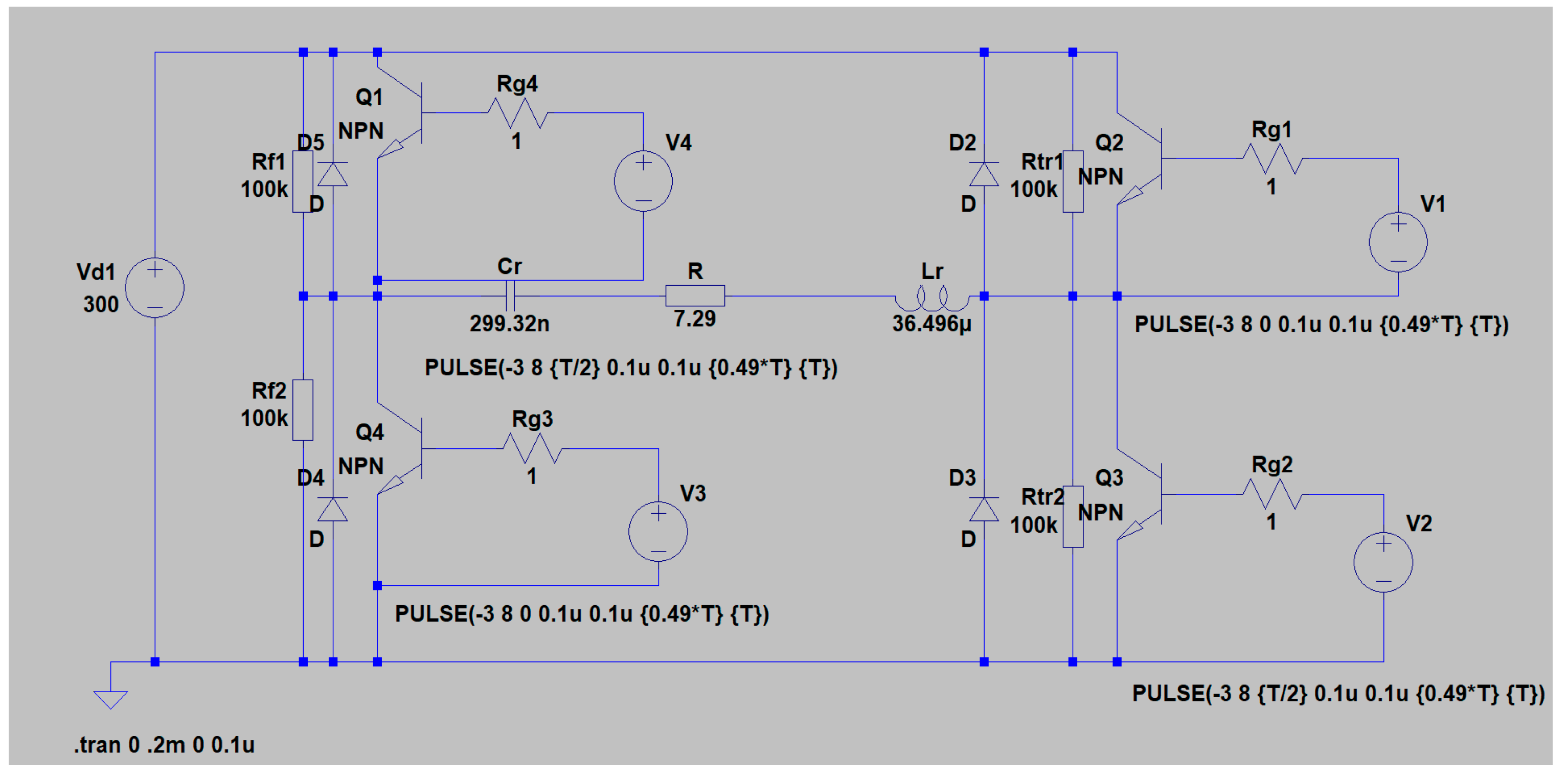
As a result of the design, the following values of the circuit elements were determined: R = 7.29 Ω, L = 36.496 μH and C = 299.32 nF. For design purposes, a DC power supply value of 300 V was chosen.
In Figure 18 shows simulation results from the study of the designed DC/AC converter - series resonant inverter with reverse diodes. In sequence from top to bottom, the current consumed by the DC power source (it is formed by the sequential operation of transistors and reverse diodes) Id and the output voltage UOUT are presented. Characteristic of the considered power topology is that during the conduction of the reverse diodes, energy is returned to the DC power source. For this reason, negative sections are observed in the form of the input current, which correspond to the release of energy from the AC circuit to the DC power source. The simulation model by which these results were obtained is given in Appendix A at the end of the manuscript.
Table 4 compares the results calculated using the unified analysis and the full-bridge resonant inverter with reverse diodes design methodology based on it with those obtained from the simulator and experiments.
Data listed in Table 3 shows that for all values determined at design, mistake is less than 5 %.
6. Discussion and Conclusions
When summarizing the presented results obtained from the design, computer simulations and from the operation of real power electronic devices, it was found that they differ by no more than 5%. The accuracy achieved is good in view of the fact that capacitors are produced in a discrete order of values and in practice it is not possible to achieve exactly the values determined by the design methodologies. On the other hand, it is characteristic of the passive components of the power electronic devices (inductors and capacitors) that they have significant production tolerances - 15-20%, and moreover, their values are greatly influenced by the operating mode. In this sense, the main idea presented in the manuscript is to propose a simplified design procedure for resonant inverters with application for induction technologies. In the presented design approach, the case is considered when the alternating current circuit of the inverters is reduced to a series complex resistance of an active-capacitive character. This is necessary to switch all semiconductor devices used in the prototyping of power electronic devices, including single-operation thyristors. This is necessary due to the fact that, regardless of the development of the modern element base, thyristors have not yet lost their relevance in the spectrum of the largest powers. A similar approach to converting the output circuits is also applicable to other tunings of the resonant circuits making up the output circuits of the inverters. The main results and conclusions of the research are as follows:
- Based on the analysis of resonant inverters with and without reverse diodes, operating in different modes, their transmission characteristics were found. In this way, it becomes possible to unify all operating modes, as well as schematic options for load compensation;
- A unified approach is proposed to describe the behavior of the resonant output circuits of resonant inverters used for power sources to implement various electrical technologies, based on the dephasing angles between the currents and voltages in the resonant circuits;
- The dependences of the ratio U/UOUT are derived analytically and graphically constructed for the most common cases of complicated output circuits in resonant inverters operating in different modes;
- Design methodologies for the main types of resonant inverters for induction heating applications have been created and verified.
By using appropriate numerical coefficients [28,30], the proposed methods can be used to design other circuit varieties of resonant inverters, including frequency-doubled resonant inverters.
The appropriate transformation of the alternating current circuit of the inverters leads to the fact that the electronic processes in them are reduced to the description of an equivalent series resonant circuit. In this way, the developed methods become convenient and easy to calculate, and this is not at the expense of their accuracy. In this sense, the proposed design approach is suitable for formalizing and algorithmizing the design process, including implementation in mathematical software. One expansion and deepening of these studies is, based on data collection from multiple projects, to apply artificial intelligence techniques to optimize and refine the design process of power electronic devices and systems.
Funding
This research was funded by Bulgarian National Scientific Fund, grant number KП-06-H57/7/16.11.2021, and the APC was funded by KП-06-H57/7/16.11.2021.
Institutional Review Board Statement
Not applicable.
Informed Consent Statement
Not applicable.
Data Availability Statement
Not applicable.
Acknowledgments
This research was carried out within the framework of the project “Artificial Intelligence-Based modeling, design, control and operation of power electronic devices and systems”, KП-06-H57/7/16.11.2021, Bulgarian National Scientific Fund.
Conflicts of Interest
The author declare no conflict of interest.
Appendix A
The simulation models of the designed DC/AC converters are presented in the appendix A. The graphical and numerical results presented in the manuscript were obtained through these models. Figure A1 shows the simulation model of a parallel resonant inverter with soft comutation. As already commented, due to the absence of thyristors in the standard semiconductor element model libraries in the used simulator, a series connection of a bipolar NPN transistor and a diode is used in the simulation studies.
Figure A1.
Simulation model of a parallel resonant inverter with soft commutation.
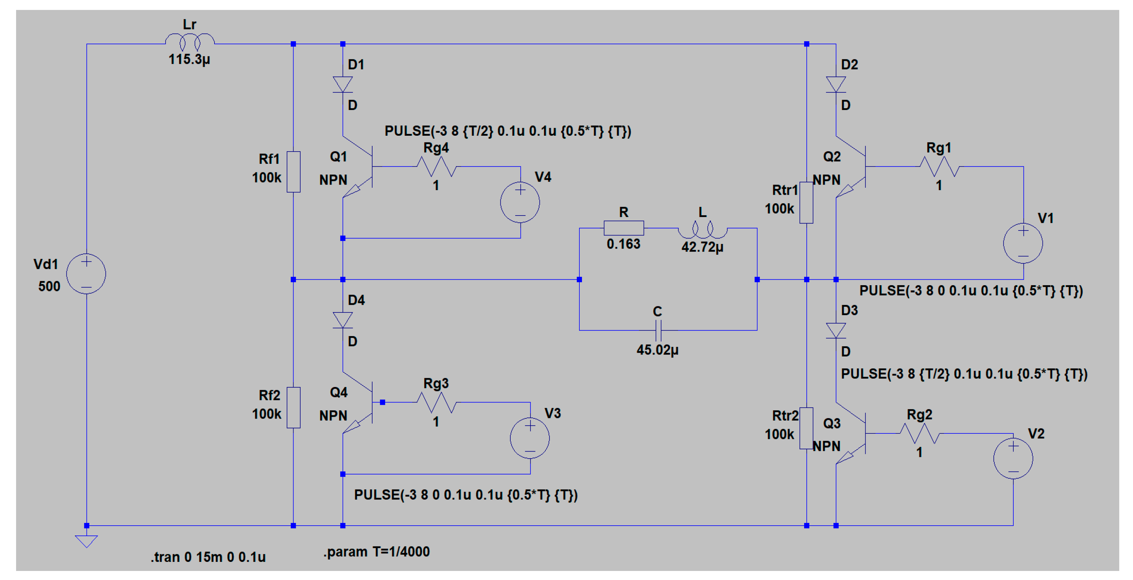
Figure A2 shows the simulation model of a series-parallel inverter with hard commutation and without reverse diodes.
Figure A2.
Simulation model of a series-parallel resonant inverter with hard commutation.
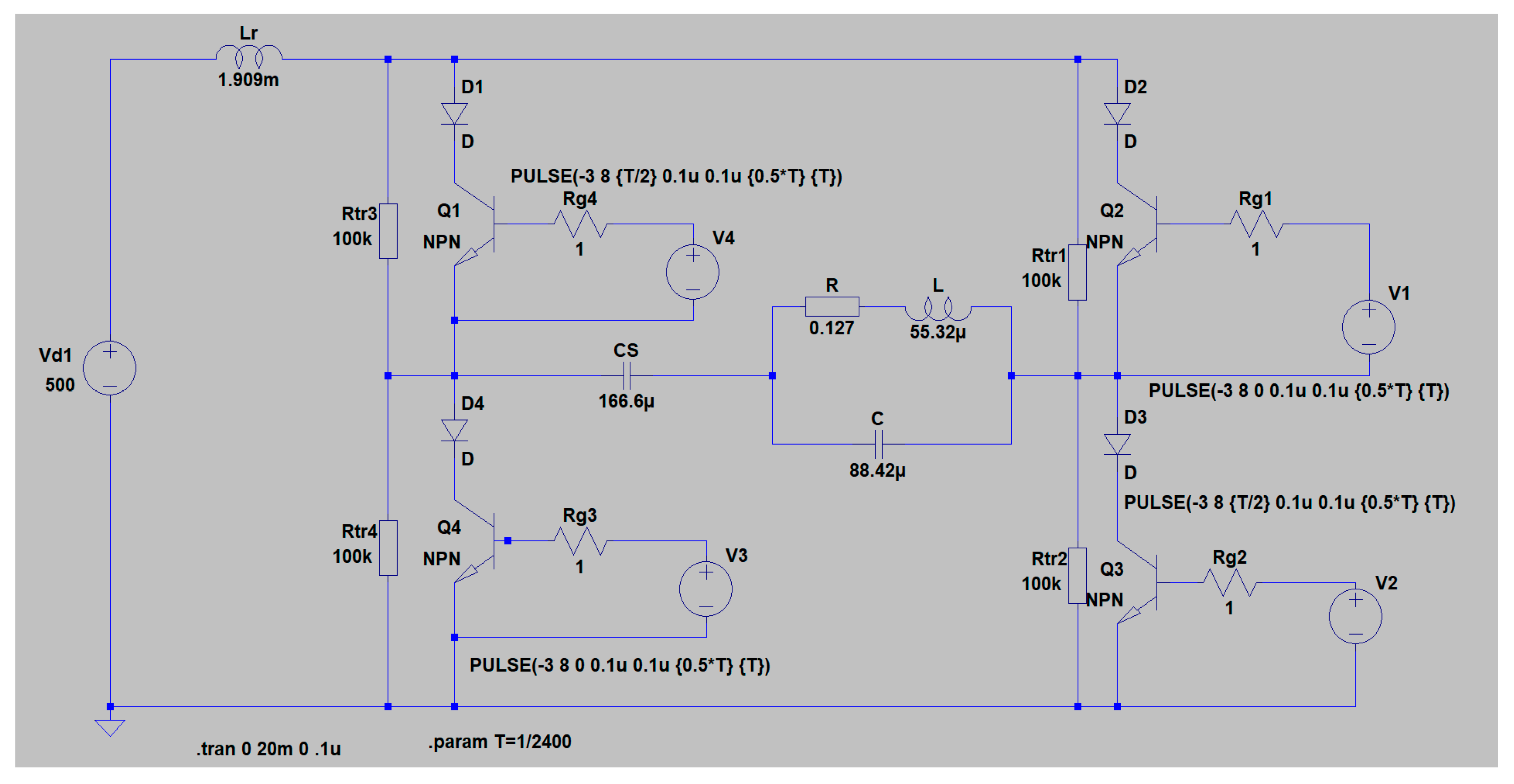
Figure A3 shows the simulation model of a parallel-series resonant inverter with hard commutation, without reverse diodes.
Figure A3.
Simulation model of a parallel-series resonant inverter with hard commutation.
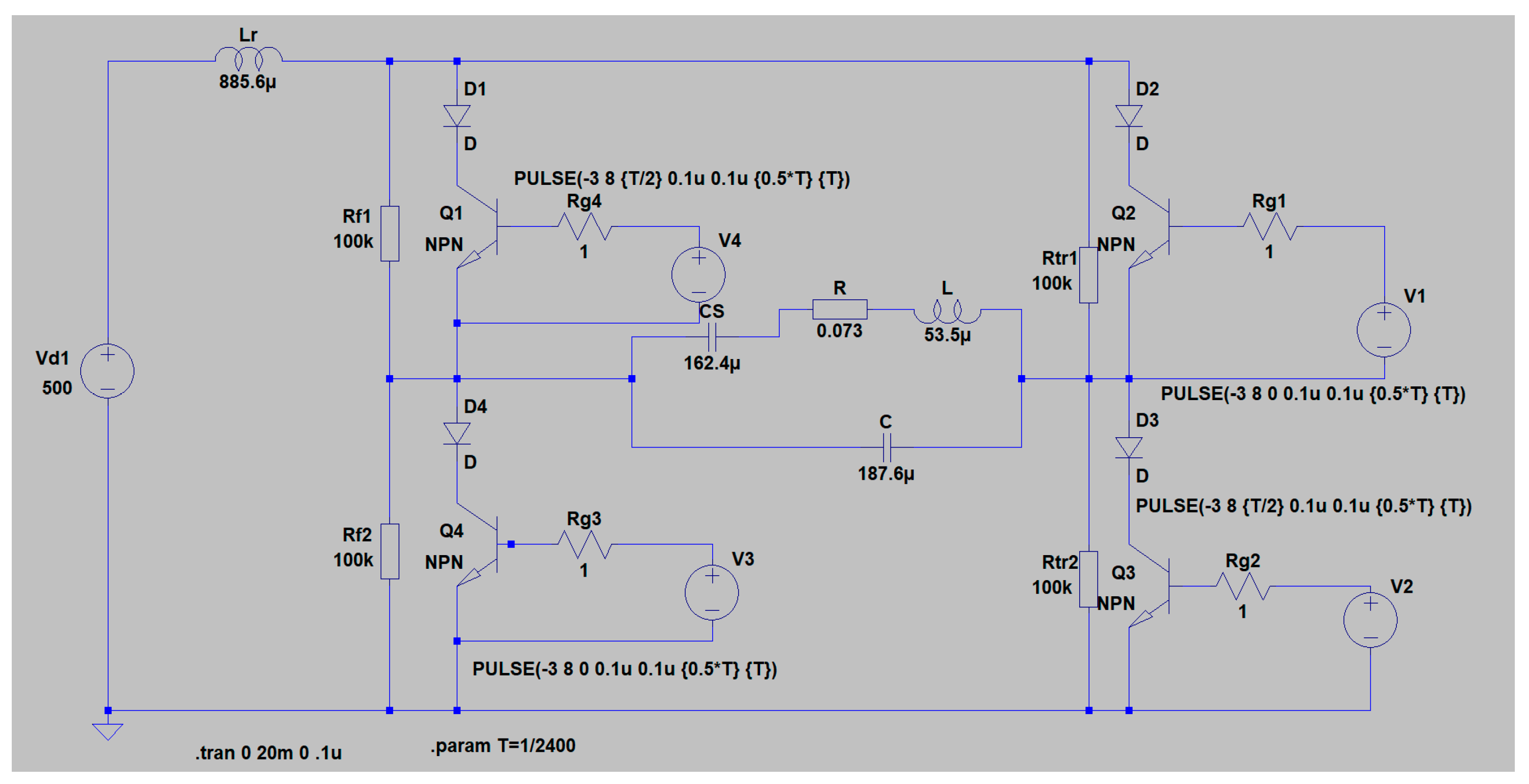
Figure A4 shows the simulation model of a series resonant inverter with reverse diodes.
Figure A4.
Simulation model of a series resonant inverter with reverse diodes.
References
- Kazimierczuk, M.K.; Czarkowski, D. Resonant Power Converters, 2nd ed.; IEEE Press and John Wiley & Sons: New York, NY, USA, 2011; pp. 1–595. ISBN 978-0-470-90538-8. [Google Scholar]
- Ned Mohan, U.; Tore, M.; Robbins; William, P. Power Electronics—Converters, Applications, and Design, 3rd ed.; John Wiley & Sons: Hoboken, NJ, USA, 2003.
- Zinoviev, G. Fundamentals of Power Electronics—Part II; Novosibirsk State University: Novosibirsk, Russia, 2004. (in Russian) [Google Scholar]
- Rashid, M.H. Power Electronics Handbook: Devices, Circuits, and Applications; Academic Press: Cambridge, MA, USA, 2007. [Google Scholar]
- Erickson, R.W.; Maksimovic, D. Fundamentals of Power Electronics, 2nd ed.; Kluwer Academic Publishers Group: Bonn, Germany, 2001. [Google Scholar]
- V. Rudnev, D. Loveless, R. Cook, Handbook of Induction Heating, Second Edition, Publisher: CRC Press, 2017, ISBN: 978-1-1387-4874-3,1138748749,978-1-4665-5395-8.
- P. M. Roberts, “Introduction to Brazing Technology”, CRC, © 2016 by Taylor & Francis Group, LLC, ISBN: 978-1-4987-5845-1,1498758452.
- S. Weis, “Research trends in brazing and soldering”, Weld. Tech. Rev., vol. 89, no. 7, Jul. 2017. [CrossRef]
- John Davies, Conduction and induction heating, Series: IEE power engineering series 11, Publisher: P. Peregrinus Ltd. on behalf of the Institution of Electrical Engineers, Year: 1990, ISBN: 0-86341-174-6,978-0-86341-174-8. 0.
- Johnson, I. Agbinya, "20 Induction Cooking and Heating," in Wireless Power Transfer 2nd Edition, River Publishers, 2016, pp.681-702.
- Antchev M., Technologies for Electrical Power Conversion: Efficiency and Distribution, Methods and Processes, IGI Global, USA, 2010.
- Cerezo Jorge, „IGBT Definition for Single Ended Induction Heating Cookers”, Bodo´s Power Systems® - Electronics in Motion and Conversion, April 2012, ISSN: 1863-5598, 22-30. 20 April.
- Llorente S., F. Monterde, J. M. Burdío, and J. Acero, “A Comparative Study of Resonant Inverter Topologies Used in Induction Cookers”, Applied Power Electronics Conference and Exposition, APEC 2002, Seventeenth Annual IEEE, Volume: 2, pp.1168-1174.
- Rodriguez-Estrada, H.; Rodriguez-Segura, E.; Orosco-Guerrero, R.; Gordillo-Tapia, C.; Martínez-Nolasco, J. Novel Multibus Multivoltage Concept for DC-Microgrids in Buildings: Modeling, Design and Local Control. Appl. Sci. 2023, 13, 2405. [Google Scholar] [CrossRef]
- Singh, P.P.; Wen, F.; Palu, I.; Sachan, S.; Deb, S. Electric Vehicles Charging Infrastructure Demand and Deployment: Challenges and Solutions. Energies 2023, 16, 7. [Google Scholar] [CrossRef]
- Al-Thani, H.; Koç, M.; Isaifan, R.J.; Bicer, Y. A Review of the Integrated Renewable Energy Systems for Sustainable Urban Mobility. Sustainability 2022, 14, 10517. [Google Scholar] [CrossRef]
- C. Mu et al., "A Decentralized Market Model for a Microgrid With Carbon Emission Rights," in IEEE Transactions on Smart Grid, vol. 14, no. 2, pp. 1388–1402, March 2023. [CrossRef]
- Rimal, B.P.; Kong, C.; Poudel, B.; Wang, Y.; Shahi, P. Smart Electric Vehicle Charging in the Era of Internet of Vehicles, Emerging Trends, and Open Issues. Energies 2022, 15, 1908. [Google Scholar] [CrossRef]
- G. Pavlov, A. Obrubov and I. Vinnychenko, "Design Procedure of Static Characteristics of the Resonant Converters," 2021 IEEE 3rd Ukraine Conference on Electrical and Computer Engineering (UKRCON), Lviv, Ukraine, 2021, pp. 401–406. [CrossRef]
- J. S. Artal-Sevil, F. Rivases, J. Beyza and M. A. Evangelista, "Design and Implementation of a High-Power Resonant Converter for an Induction Steel-Melting Furnace," 2021 IEEE International Autumn Meeting on Power, Electronics and Computing (ROPEC), Ixtapa, Mexico, 2021, pp. 1–6. [CrossRef]
- A. Kumar, A. Awasthi, O. Salari, A. Laha, A. Mathew and P. Jain, "A Time-Domain Based APP Designer For Resonant Converters With GUI Features," 2020 IEEE Applied Power Electronics Conference and Exposition (APEC), New Orleans, LA, USA, 2020, pp. 2860-2867. [CrossRef]
- S. -Y. Yu, "A new compact and high efficiency resonant converter," 2016 IEEE Applied Power Electronics Conference and Exposition (APEC), Long Beach, CA, USA, 2016, pp. 2511-2517. [CrossRef]
- Y. -R. Yang, "Analysis and design of a current-fed push-pull parallel-resonant converter for cooker magnetrons," 2016 IEEE International Conference on Sustainable Energy Technologies (ICSET), Hanoi, Vietnam, 2016, pp. 300-305. [CrossRef]
- S. V. Mollov and M. P. Theodoridis, “A comparison and optimum design of reluctance-controlled classical load-resonant converters,” 2008 13th International Power Electronics and Motion Control Conference, Poznan, Poland, 2008, pp. 350-356. [CrossRef]
- X. Li, S. Chen, Y. Tang, Y. Zhang and X. Zhang, “Reduced-Order Equivalent Circuit Model of Series Resonant Converter Considering the Interaction between Resonant Elements,” 2021 IEEE Energy Conversion Congress and Exposition (ECCE), Vancouver, BC, Canada, 2021, pp. 2728-2732. [CrossRef]
- Hinov, N. A Unified Approach to the Analysis of DC/AC Converters, Based on the Study of Electromagnetic Processes in a Series RLC Circuit. Electronics 2023, 12, 983.
- Todorov, T.S.; Madzharov, N.D.; Alexiev, D.T.; Ivanov, P.T. Autonomous inverters; Technical University of Gabrovo, Gabrovo, Bulgaria.
- Hinov, N.L. Power Converters of Electrical Energy with Industrial Application. Ph.D. Thesis, Technical University, Sofia, Bulgaria, 1998. (In Bulgarian).
- Gradinarov, N.P. Analysis and Development of Autonomous Resonant Inverters with Electrical Application. Ds.C. thesis, Technical University of Sofia, Sofia, Bulgaria, 2002. (in Bulgarian).
- Berkovich, E.I.; Ivenskyi, G.V. and other; High-frequency thyristor converters for electrical devices, Energoatomizdat, Leningrad, Russia, 1983. (in Russian).
- Fluxtrol Inc. Available online: https://fluxtrol.com/induction-coils (accessed on 15 March 2021).
- Hinov, N. Quasi-Boundary Method for Design Consideration of Resonant DC-DC Converters. Energies 2021, 14, 6153. [CrossRef]
Figure 1.
Full-bridge power schemes of resonant DC/AC converters. (a) parallel thyristor inverter; (b) parallel thyristor inverter with split resonant inductance; (c) series thyristor resonant DC/AC converter with split resonant inductance; (d) transistor resonant DC/AC converter with reverse diodes.
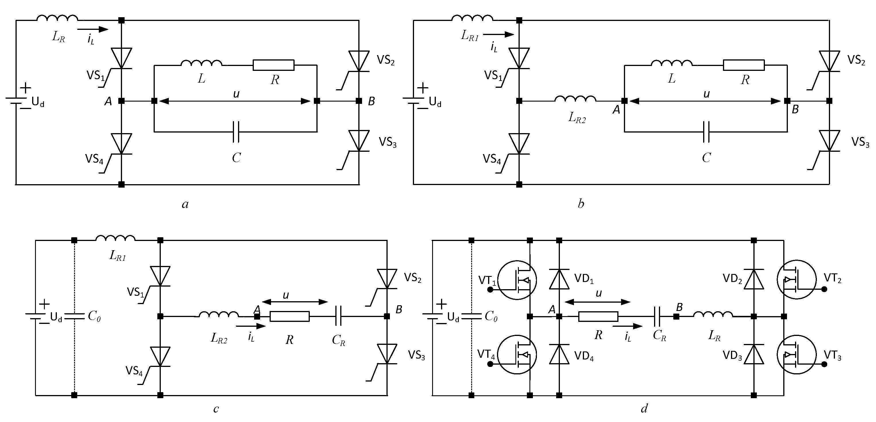
Figure 2.
Generalized equivalent circuit of resonant DC/AC converters with electro-technological application.
Figure 2.
Generalized equivalent circuit of resonant DC/AC converters with electro-technological application.
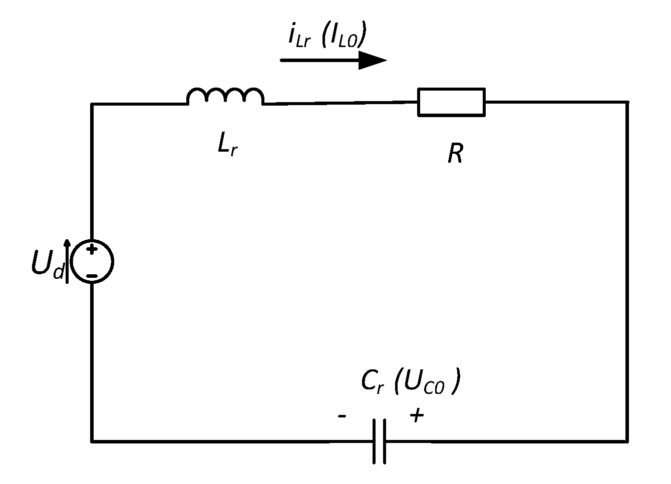
Figure 3.
Operating modes of resonant inverters without reverse diodes.
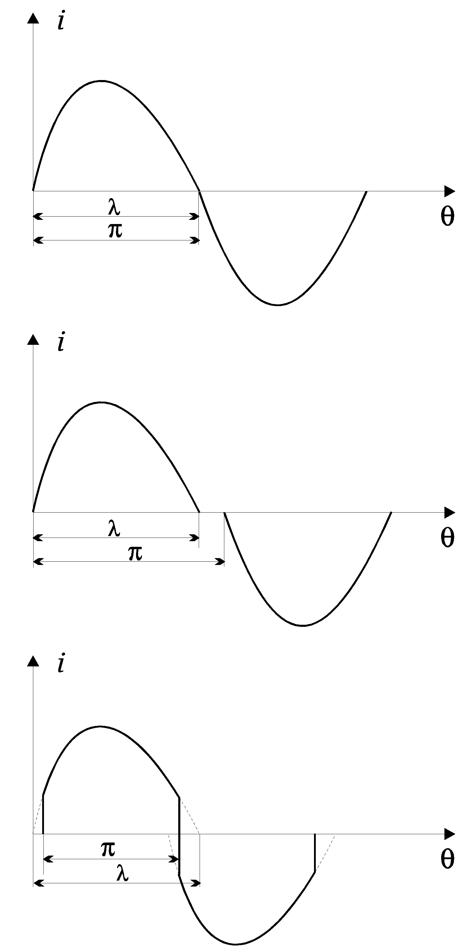
Figure 4.
Graphic constructions explaining the difference in the shape of the resonant current when resonant inverter with reverse diodes operating with a control frequency equal to the resonant (ω = ω0) and a mode with a control frequency above (ω> ω0) and subresonant (ω <ω0).
Figure 4.
Graphic constructions explaining the difference in the shape of the resonant current when resonant inverter with reverse diodes operating with a control frequency equal to the resonant (ω = ω0) and a mode with a control frequency above (ω> ω0) and subresonant (ω <ω0).
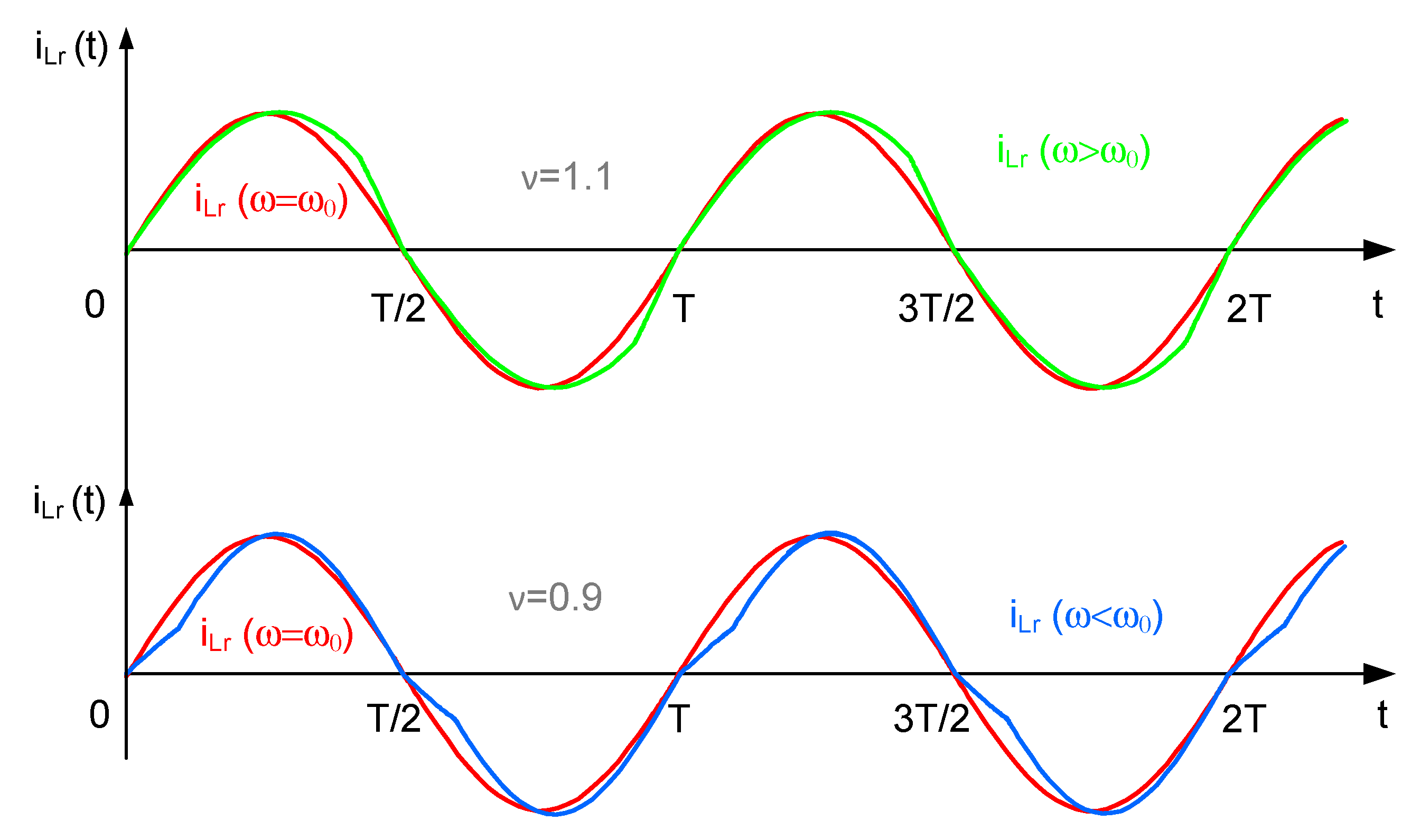
Figure 5.
Evaluation of the influence of the parameters of the equivalent resonant circuit of on the shape of the current in the AC circuit of the inverter (a) phase difference of the first harmonic of the current; (b) current ripple factor.
Figure 5.
Evaluation of the influence of the parameters of the equivalent resonant circuit of on the shape of the current in the AC circuit of the inverter (a) phase difference of the first harmonic of the current; (b) current ripple factor.
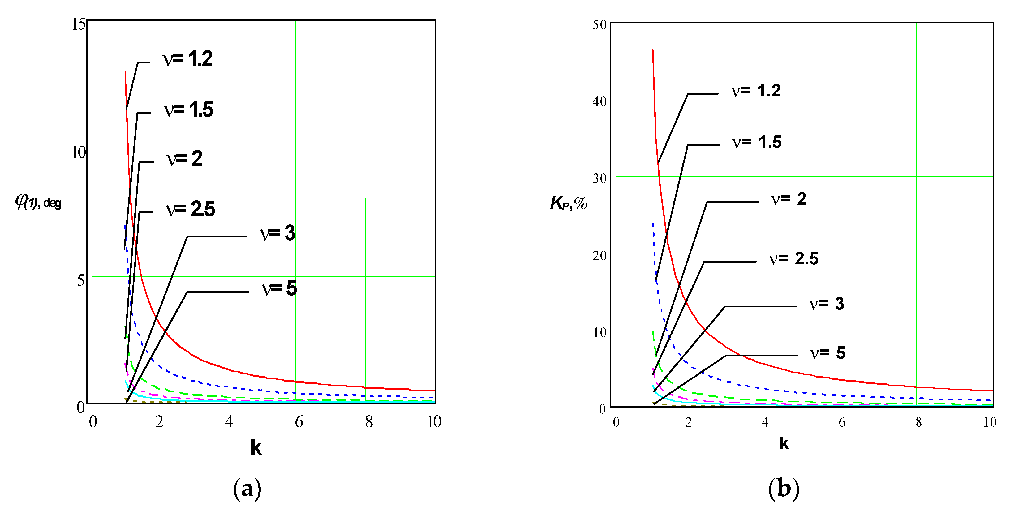
Figure 6.
Series-parallel resonant output circuit.
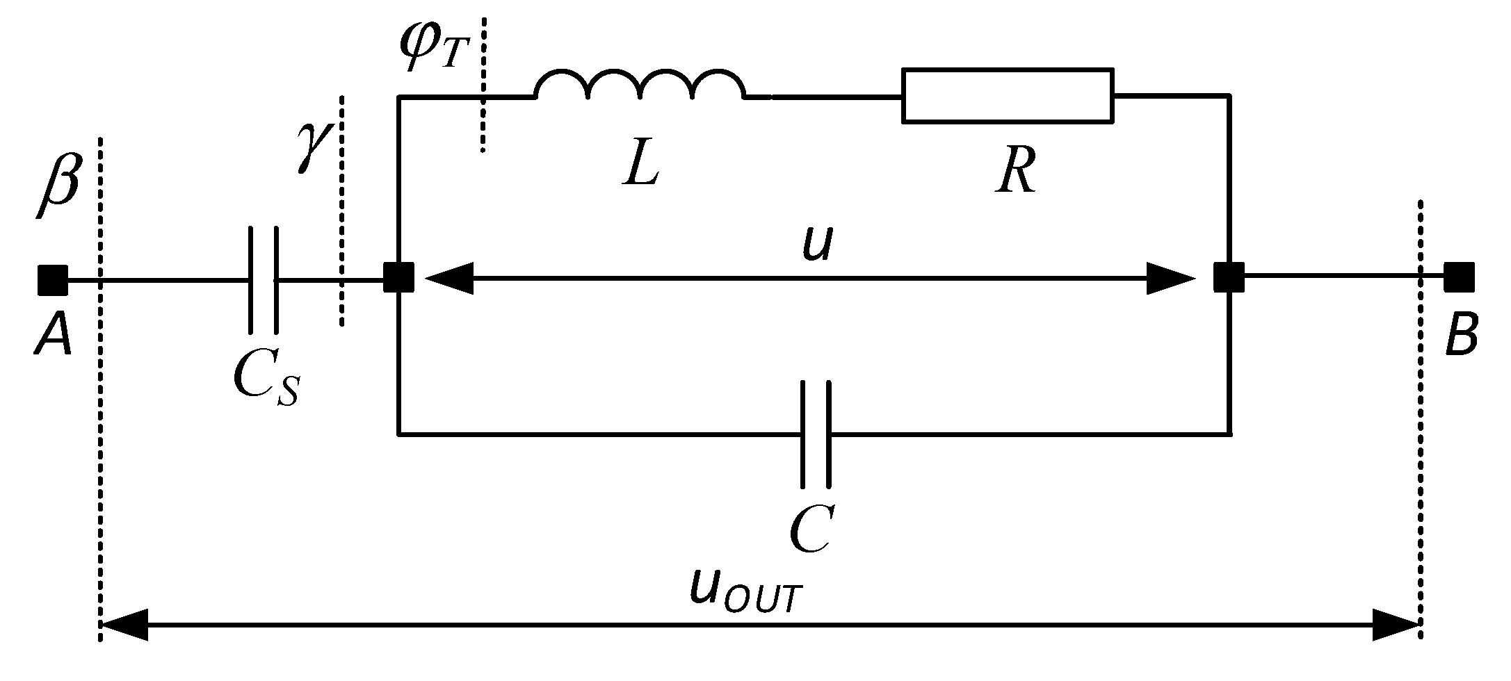
Figure 7.
Conversions of series-parallel resonant output circuit to series equivalent.
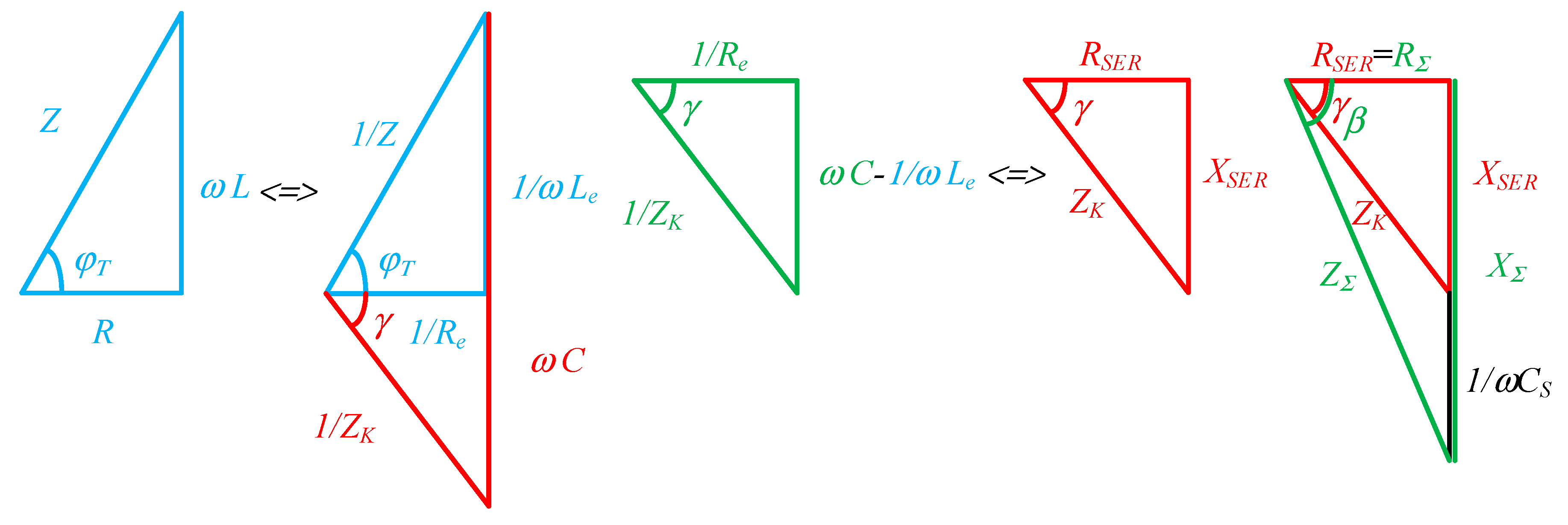
Figure 8.
Characteristics of a series-parallel resonant output circuit, when operating in soft commutation mode: (a) when changing the load power factor cosφT; (b) when changing the detuning factor ν; (c) when changing the coefficient of variation k.
Figure 8.
Characteristics of a series-parallel resonant output circuit, when operating in soft commutation mode: (a) when changing the load power factor cosφT; (b) when changing the detuning factor ν; (c) when changing the coefficient of variation k.
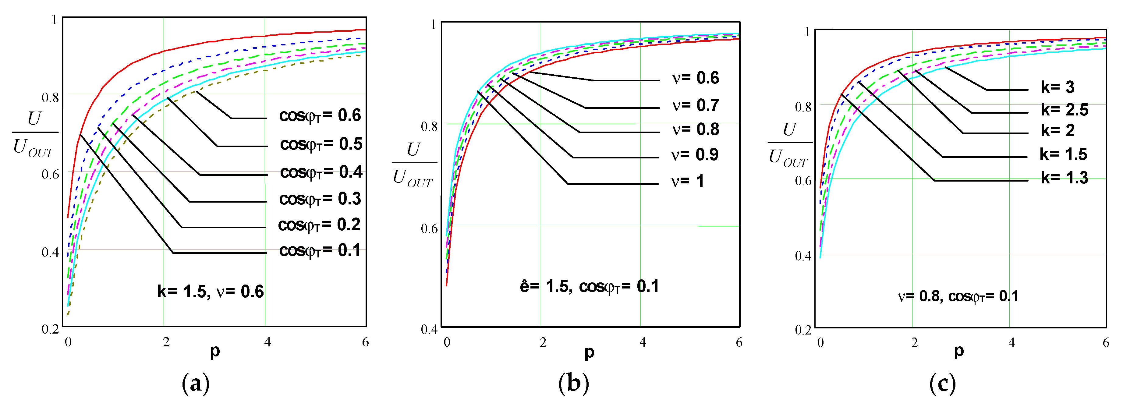
Figure 9.
Characteristics of a series-parallel resonant output circuit, when operating in hard commutation mode: (a) when changing the load power factor cosφT; (b) when changing the detuning factor ν; (c) when changing the coefficient of variation k.
Figure 9.
Characteristics of a series-parallel resonant output circuit, when operating in hard commutation mode: (a) when changing the load power factor cosφT; (b) when changing the detuning factor ν; (c) when changing the coefficient of variation k.
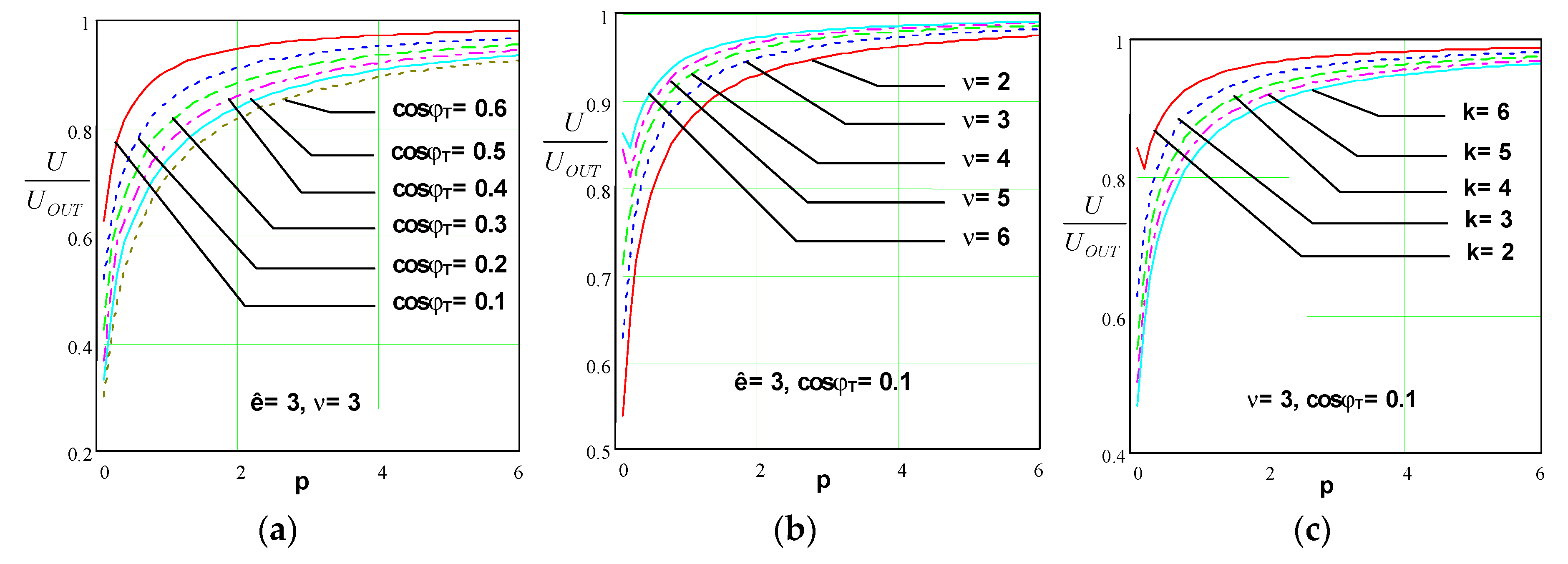
Figure 10.
Parallel-series resonant output circuit.
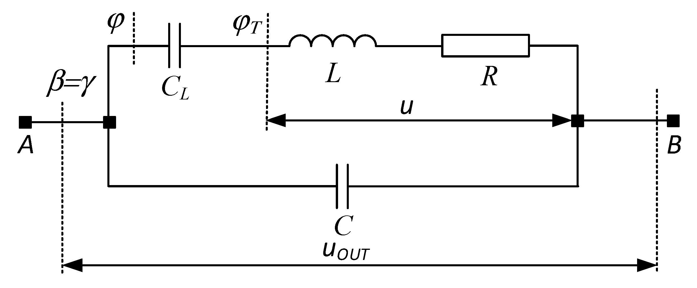
Figure 11.
Conversions of a parallel-series resonant output circuit to a series RC circuit.
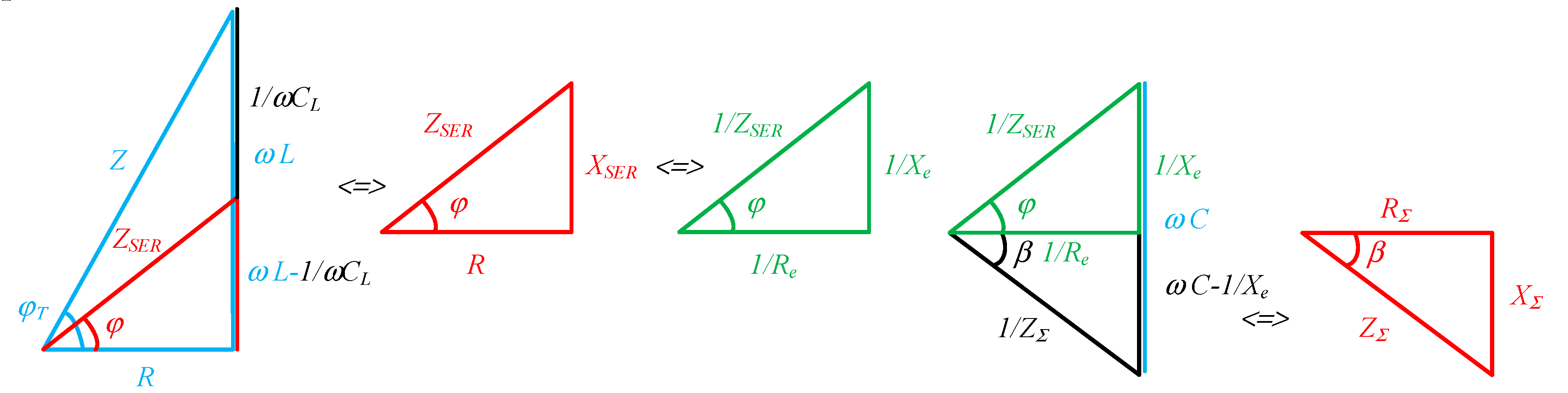
Figure 12.
Characteristics of a parallel-series resonant output circuit, when operating in soft commutation mode: (a) when changing the load power factor cosφT; (b) when changing the detuning factor ν; (c) when changing the coefficient of variation k.
Figure 12.
Characteristics of a parallel-series resonant output circuit, when operating in soft commutation mode: (a) when changing the load power factor cosφT; (b) when changing the detuning factor ν; (c) when changing the coefficient of variation k.
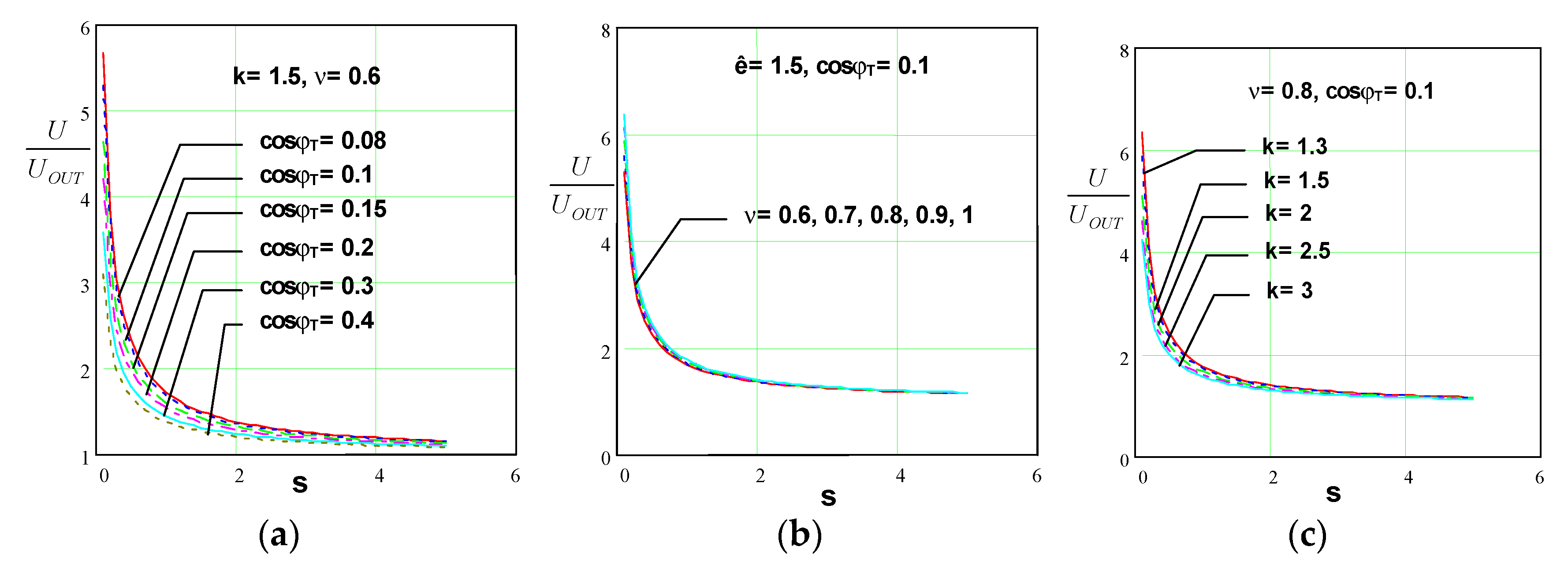
Figure 13.
Characteristics of a parallel-series resonant output circuit, when operating in hard commutation mode: (a) when changing the load power factor cosφT; (b) when changing the detuning factor ν; (c) when changing the coefficient of variation k.
Figure 13.
Characteristics of a parallel-series resonant output circuit, when operating in hard commutation mode: (a) when changing the load power factor cosφT; (b) when changing the detuning factor ν; (c) when changing the coefficient of variation k.
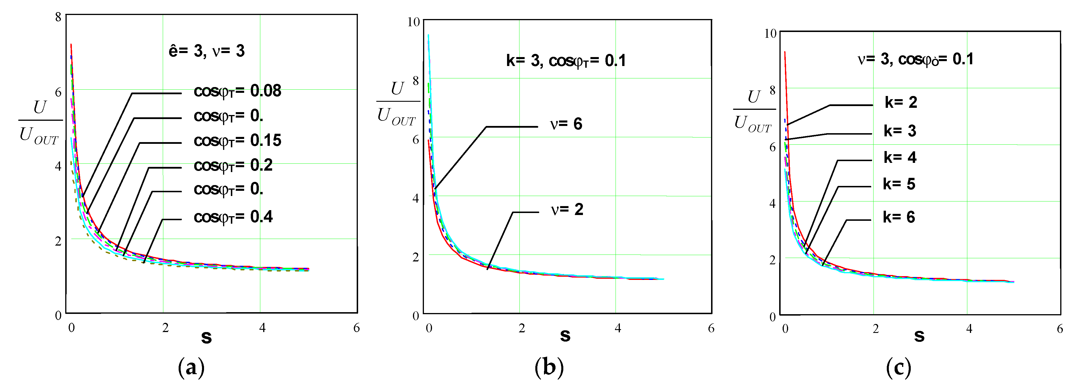
Figure 14.
Series-parallel-parallel-series resonant output circuit.
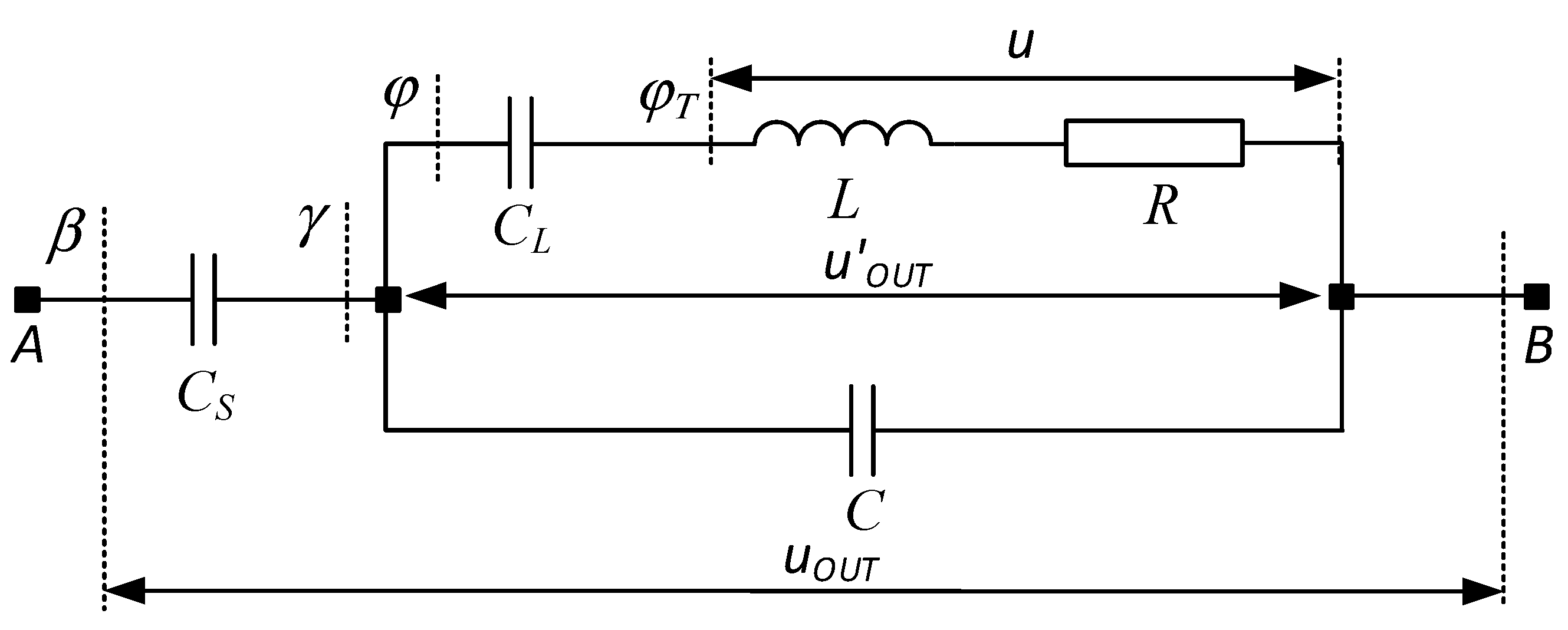
Figure 15.
Time diagram of the resonant inductance current - iL, output voltage - uOUT and voltage across thyristor VS1 – uVS1 in the designed and simulated parallel resonant inverter.
Figure 15.
Time diagram of the resonant inductance current - iL, output voltage - uOUT and voltage across thyristor VS1 – uVS1 in the designed and simulated parallel resonant inverter.
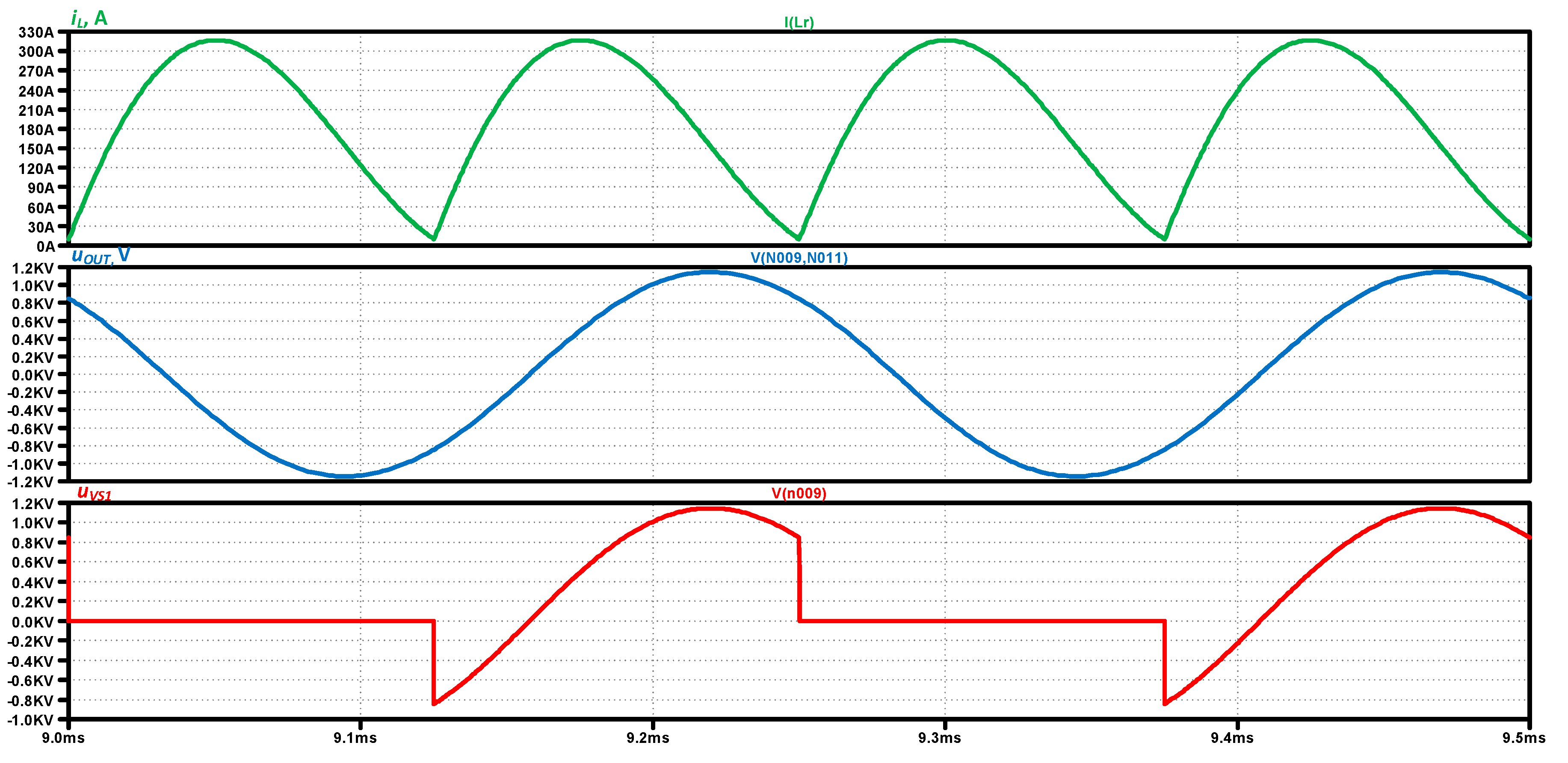
Figure 16.
Time diagram of the input current - iLR, output voltage - uOUT, load voltage - u and voltage across thyristor VS1 – uVS1 in the designed and simulated series-parallel current source inverter.
Figure 16.
Time diagram of the input current - iLR, output voltage - uOUT, load voltage - u and voltage across thyristor VS1 – uVS1 in the designed and simulated series-parallel current source inverter.
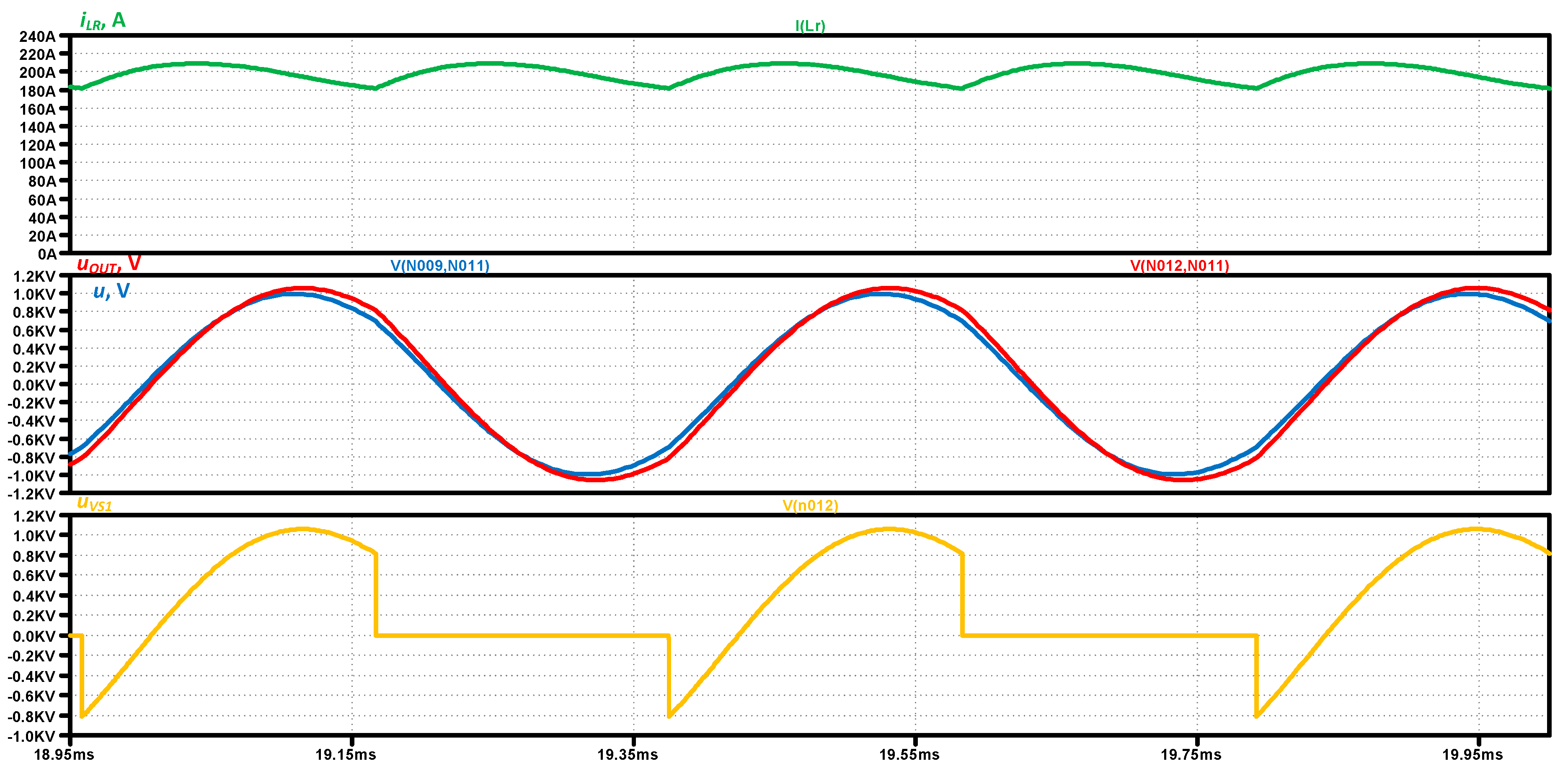
Figure 17.
Time diagram of the input current - iLR, output voltage - uOUT, load voltage - u and voltage across thyristor VS1 – uVS1 in the designed and simulated parallel-series current source inverter.
Figure 17.
Time diagram of the input current - iLR, output voltage - uOUT, load voltage - u and voltage across thyristor VS1 – uVS1 in the designed and simulated parallel-series current source inverter.
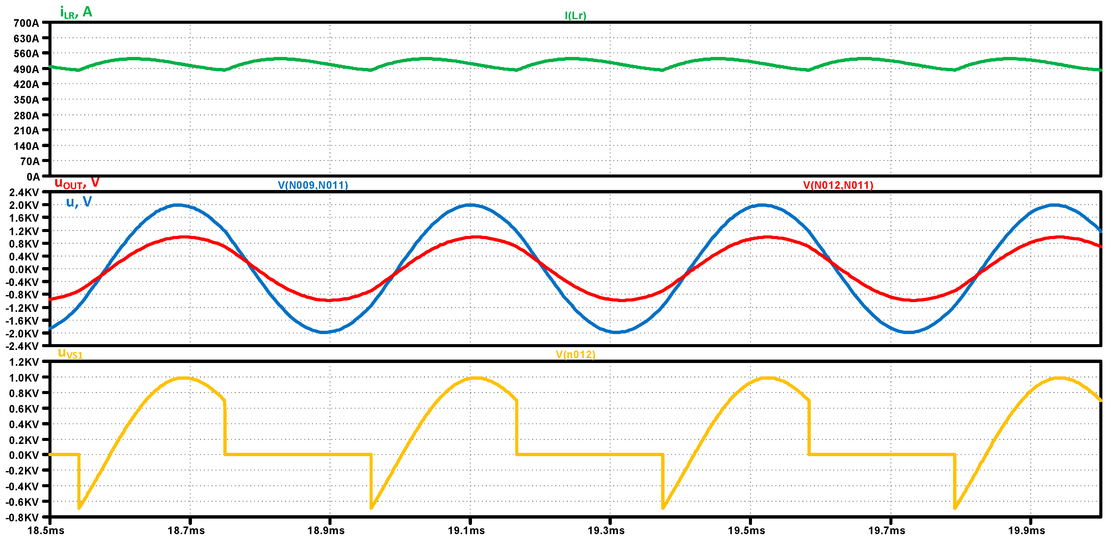
Figure 18.
Time diagram of the input current – Id and output voltage - uOUT.
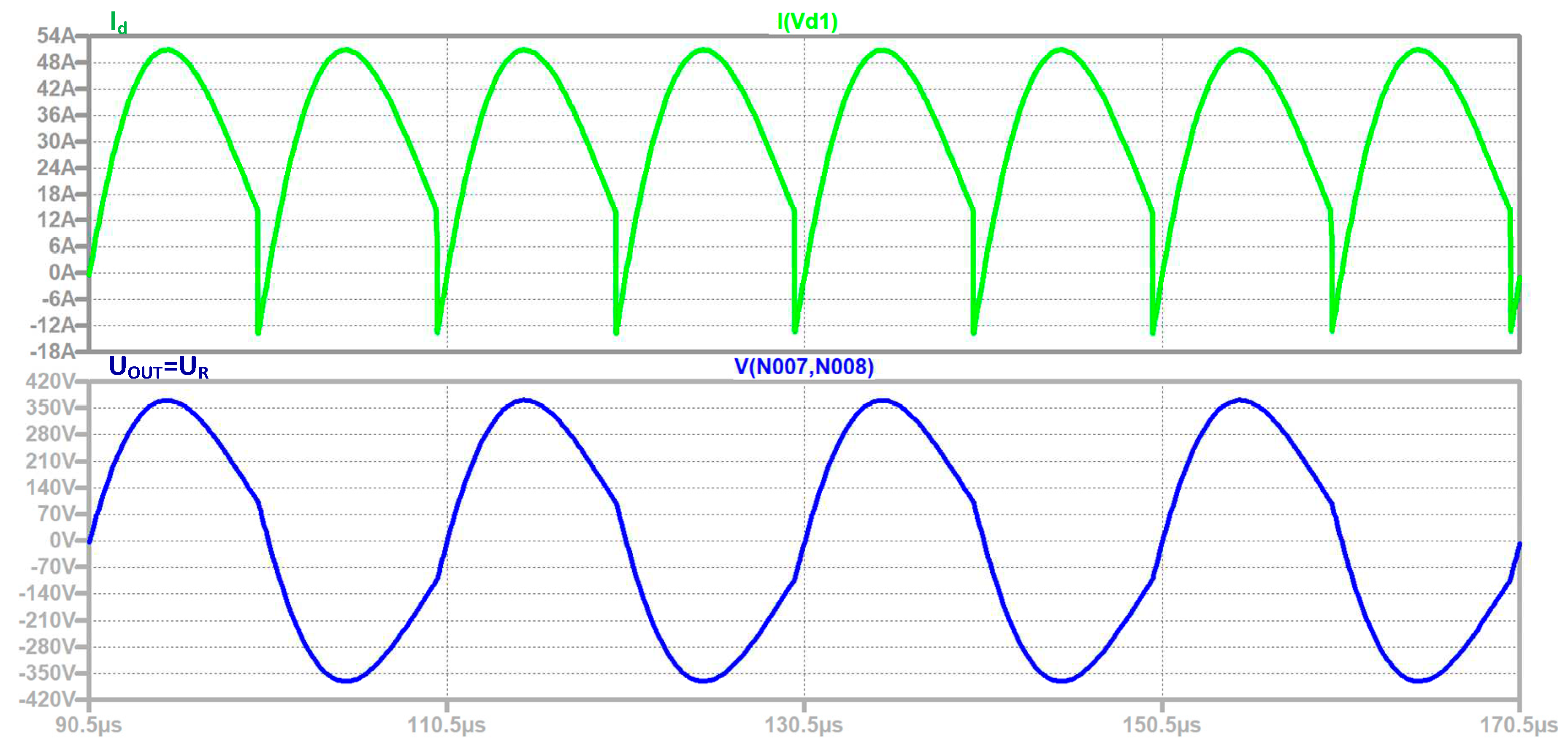

Table 1.
Output data and obtained results from simulation and experiment for full-bridge parallel resonant inverter.
Table 1.
Output data and obtained results from simulation and experiment for full-bridge parallel resonant inverter.
| Intput data | Computer Simulation | Experiment |
|---|---|---|
| UOUT, V = 850 | 814.47 | 824.25 |
| Id, A = 200 | 195.04 | 196.2 |
| Imax, A = 314.16 | 316.85 | 315.87 |
| tq, μs = 40.33 | 41 | 40.7 |
Table 2.
Output data and obtained results from simulation and experiment for full-bridge thyristor series-parallel current source inverter.
Table 2.
Output data and obtained results from simulation and experiment for full-bridge thyristor series-parallel current source inverter.
| Intput data | Computer Simulation | Experiment |
|---|---|---|
| UOUT, V = 800 | 776.8 | 780.25 |
| U, V = 750 | 728 | 730 |
| Id, A = 200 | 198.39 | 198.12 |
| tq, μs = 53.33 | 51 | 49.5 |
Table 3.
Output data and obtained results from simulation and experiment for full-bridge thyristor parallel-series current inverter.
Table 3.
Output data and obtained results from simulation and experiment for full-bridge thyristor parallel-series current inverter.
| Intput data | Computer Simulation | Experiment |
|---|---|---|
| UOUT, V = 750 | 723.25 | 728.45 |
| U, V = 1500 | 1440.7 | 1444.35 |
| Id, A = 500 | 512.28 | 510.12 |
| tq, μs = 48.66 | 48 | 48.5 |
Table 4.
Output data and obtained results from simulation and experiment for full-bridge transistor resonant inverter with reverse diodes.
Table 4.
Output data and obtained results from simulation and experiment for full-bridge transistor resonant inverter with reverse diodes.
| Intput data | Computer Simulation | Experiment |
|---|---|---|
| UOUT, V = 270 | 268.73 | 267.45 |
| Id, A = 33.333 | 33.097 | 32.9 |
Disclaimer/Publisher’s Note: The statements, opinions and data contained in all publications are solely those of the individual author(s) and contributor(s) and not of MDPI and/or the editor(s). MDPI and/or the editor(s) disclaim responsibility for any injury to people or property resulting from any ideas, methods, instructions or products referred to in the content. |
© 2023 by the authors. Licensee MDPI, Basel, Switzerland. This article is an open access article distributed under the terms and conditions of the Creative Commons Attribution (CC BY) license (http://creativecommons.org/licenses/by/4.0/).
Copyright: This open access article is published under a Creative Commons CC BY 4.0 license, which permit the free download, distribution, and reuse, provided that the author and preprint are cited in any reuse.


