
Submitted:
07 April 2023
Posted:
10 April 2023
You are already at the latest version
Abstract
Solid oxide cells are capable of efficiently converting various chemical energy carriers to electricity and vice versa. The urgent challenge nowadays is the faster degradation rate compared with other fuel cell/electrolyzer technologies. To understand the degradation mechanisms, simulation of a solid oxide cell is helpful. Since most previous research developed models using commercial software, such as COMSOL and ANSYS Fluent, a gap for knowledge transfer is being gradually formed between academia and industry due to licensing issues. This paper introduces a multiphysics model, developed by a computational code, openFuelCell2. The code is implemented with an open-source library, OpenFOAM. It accounts for momentum transfer, mass transfer, electrochemical reactions and metal interconnect oxidation. The model can precisely predict I-V curves under different temperatures, fuel humidity and operation modes. Comparison between OpenFOAM and COMSOL simulations shows good agreement. The metal interconnect oxidation is modelled, which can predict the thickness of the oxide scale under different protective coatings. Simulations are conducted by assuming an ultra-thin film resistance on the rib surface. It is revealed that coatings fabricated by atmospheric plasma spraying can efficiently prevent metal interconnect oxidation, with a contribution of only 0.53 \% to the total degradation rate.
Keywords:
solid oxide cell
; multiphysics modelling
; OpenFOAM
; openFuelCell2
; metal interconnect oxidation
1. Introduction
Transition to the renewable energy system where solar and wind energy prevail leads to a challenge to the grid balance. Applying solid oxide cells (SOCs) as energy storage and conversion devices may be part of the solution to this problems. Their operation at high temperatures provides several advantages such as high efficiencies, possibility of sector coupling on the heat side, the capability of being reversibly operated, and the tolerance to various fuels. In order to increase the lifetime of SOCs, their degradation behaviour should be studied as it obstructs the long-term operation. Significant degradation mechanisms, such as Ni agglomeration and Cr poisoning, are related to the local distribution of the overpotential and chemical species. However, measuring local values for these during the operation of SOCs is not only a technical challenge but also a potentially dangerous task as gas leakages, burns and electric shocks could happen. In contrast, simulation can be an efficient and safe method to visualize the local physical values. Therefore, a three-dimension model that can capture the physical processes in an SOCs is necessary.
Although there was a number of scientific findings due to simulation in the past decade [1,2,3,4,5,6,7,8], simulations are usually steady-state simulations, making it impossible to trace the degradation over time. Besides, it can be seen that many numerical investigations of SOCs were carried out with commercial software, for example, DETCHEM, ANSYS Fluent, COMSOL, etc. Mathematical models used to describe the multiphysical and multiscale transport processes in the SOCs have been incorporated into a ’black-box’. It is usually impossible to visualize the implementation of these models. In addition, the knowledge transfer may be limited within the research community due to the licence issues. In this work, the authors employed a computational code, openFuelCell2 [9,10], which has been implemented with an open-source library, OpenFOAM [11]. The code has witnessed a reliable performance in low temperature electrochemical applications, for example, the proton exchange membrane fuel cells [12,13,14,15]. This work aims to extends the capability of openFuelCell2 to high temperature applications, i.e. SOFC and SOEC. The comparison between the simulation results with openFuelCell2 and COMSOL is conducted for the basic steady-state model. A degradation model to describe the performance degradation with the evolution of time due to metal interconnect (MIC) oxide scale growth is additionally proposed and implemented into openFuelCell2. Effects of different protective coatings on MIC oxidation are discussed. Numerical simulations are performed for the F10 SOC stack design [16] in Forschungszentrum Jülich GmbH (FZJ), the detailed description of which is given in the next section.
2. Geometry of the model
It is helpful to introduce the general information of the F10 SOC stack design in FZJ first. The simplified geometry of the repeating unit of the SOC stack is shown at left-hand side of Figure 1. The standard design is an fuel-electrode supported cell (FESC) where a thick support layer at the fuel side, made of Ni/8YSZ (8mol % yttria-stabilized zirconia), provides necessary mechanical strength. The repeating unit consists of roughly 1000 µm thick Ni-mesh as the distributor and contacting element at the fuel side, a 500 µm thick support layer Ni/8YSZ [17], a 7 µm thick fuel electrode Ni/8YSZ [17], a 10 µm thick 8YSZ electrolyte [17], a 45 µm thick air electrode La0.58Sr0.4Co0.2Fe0.8O3- (LSCF) [17] and a 100 µm thick contact layer LSCF (or LCC12, La0.97Mn0.4Co0.3Cu0.3O3-). Besides, a barrier layer (GDC, gadolinia-doped ceria) is added between the electrolyte and the air electrode to prevent interfacial reaction. Furthermore, there is a protective coating on the MIC to alleviate issues of metal oxidation and Cr poisoning. In FZJ, the protective coating on the MIC surface is usually made of MnCo1.9Fe0.1O4
(MCF) applied by atmospheric plasma-spraying (APS). Another widely used coating is made of MnOx
and is added onto MIC via wet-powder-spraying (WPS). The drawback of WPS, in contrast to APS, is
that it can only generate a porous layer that can not efficiently prevents metal oxidation and chromium
poisoning. Consequently, stacks with APS coatings have better performance than stacks with WPS
coatings [18]. The MIC is made by either Crofer 22 APU or intermediate temperature metal (ITM). For
sealing the stack glass ceramic sealants are used on all bonding surfaces.
Numerical simulation of the whole geometry usually means a rather large calculation effort. With the purpose of accelerating the computation while capturing main features of the repeating unit of a real SOC stack, the following assumptions are made:
- The barrier layer and protective coating are ignored in the geometry of the model. Their effects on the resistance are considered in the electronic conductivity of the air electrode and air side contact layer.
- The metal frame is ignored in the geometry of the model.
Therefore, the computational domain in this study refers to a representative three-dimensional slice of one-channel in a real SOC stack as shown at the right-hand side of Figure 1.
3. Governing equations of the basic model
The SOC stack is a complex electrochemical device that contains different physics processes which are coupled with each other. This interplay strongly affects the performance of SOC stacks. Therefore, suitable mathematical models should be implemented otherwise the results are questionable. Although it is recommended to involve as many details as possible, several plausible simplifications can be made to alleviate the difficulty in multiphysics modelling:
- Properties of materials, such as permeability, porosity and electrical conductivity, are homogeneous and isotropic.
- All fluid is in laminar flow regime.
- Heat transfer is ignored. In other words, isothermal assumption is applied in the model.
- The quality of the inlet gas is perfect, meaning the air only has oxygen and nitrogen and fuel only has hydrogen and steam.
In this section, models of major physical processes including electrochemical reaction, momentum transfer and mass transport are present. A summary of models used in this work is shown in Table 1.
3.1. Electrochemical reaction
Electrochemical reaction is the key part in modelling SOCs due to its direct relation to I-V curves and strongly coupled with other physics. Commonly, it is simulated by the Butler-Volmer equation in Equation (1) [19]
where i is the current density, is the exchange current density, () is the anodic (cathodic) charge transfer coefficient, is the number of transferred electrons, is the Faraday constant, is the gas constant, T is the temperature, is the overpotential. In spite of the popularity of Equation (1), Mogensen et al. [20] has raised several arguments against using Equation (1) for SOCs, such as the reaction rate probably not being limited by the charge transfer. Similarly, Adler et al. [21] found that except for charge transfer, surface diffusion of chemical species and dissociative chemisorption were also important for reaction rates. As illustrated by Maria et al. [22], it could happen that high operation temperature of SOC made adsorption, diffusion and other processes be more rate-limiting than charge transfer. Additionally, in most cases linear I-V curves instead of exponentially-changed I-V curves are observed from measurement in FZJ.
In light of above reasons, in this work a linear expression of electrochemical kinetics is used shown in Equation (2) and Equation (3) [22,23]
where is the volumetric reaction current density, is the overpotential, R is a pre-factor, is the energy barrier, a is the activity of the reactant. The overpotential can be calculated by [24]
where is the ionic potential, is the electromotive potential and is the equilibrium potential defined as [22]:
where , and are molar fractions of oxygen, hydrogen and water respectively. is the Gibbs free energy change of water splitting.
Two types of current exist in SOC: ionic current and electronic current . The current and potential obey Ohm’s law:
where and are ionic conductivity and electronic conductivity that can be found in Table 2. In a porous and composite medium, the conductivity needs to be corrected by considering the effect of solid volume fraction of and tortuosity of different materials. If the number of different material properties in the medium is n, the effective conductivity is [25]:
The conservation of current is guaranteed by
where is a current source defined as following:
and is given in Equation (2) and Equation (3).
The electronic and ionic conductivity is present in Table 2. Other parameters, like the porosity and volume factions of the porous medium, are given in Table A1.
3.2. Momentum transfer
Momentum transfer of fluid happens in gas channels and porous medium. In gas channels, it is a common practice to apply Navier-Stokes (NS) equations to describe the momentum transfer as shown in Equation (14) [28]
where is the density of fluid, P is the pressure, is the velocity, is the viscosity, is the identity matrix. The continuity equation is:
where is the mass source.
In a porous medium, momentum transfer can be simulated by several models. The easiest one is the Darcy’s law considering the velocity of fluid should linearly respond to the pressure gradient:
where is the permeability of the porous medium. In spite of its conciseness, it should be kept in mind that it is an empirical relation which was originated from experimental data of water passing through sands at low velocity [29]. Therefore there are some limitations of Equation (16). For example, Darcy’s law neglects viscous forces. Besides, assuming Darcy’s law is implemented in porous medium and NS equation is used in gas channels, two calculation domains need to be defined, because Equation (14) has second-order differential terms while Equation (16) misses it. This inherent conflict leads to a trouble in setting boundary conditions at the interface between channels and porous medium. [30].
Providing by the drawbacks in Darcy’s law, it is recommended to use Darcy-Forchheimer (DF) equation which is able to be implemented in both gas channels and porous medium, as given in Equation (17) [31,32]:
where is the porosity of the porous medium. In gas channels where permeability approaches to infinity and porosity becomes one, Equation (17) can automatically become Equation (14), which avoids to set another boundary condition at the interface between gas channels and porous medium.
The data of porosity and permeability is given in Table A1.
3.3. Mass transport
Mass is conserved by Equation (18):
where c is the molar density, is the molar fraction, is the molar diffusion flux of species i and is the source term of moles of chemical specie i due to electrochemcial reactions and it is described by the following Equation (19)
where is the reaction current density, and is the number of electrons transferred in electrochemical reactions. To solve Equation (18), needs to be calculated. Several diffusion models that can be chosen. For instance, Fick’s law can be used which is the most popular model due to its simplicity and it has been successfully implemented in SOC numerical modeling [33,34]. The mathematical description is shown in Equation (20)
where is the binary diffusion coefficient for species i and j. For a multicomponent system, it is more plausible to apply the Stefan-Maxwell equation to describe the transport phenomena which is the extension of Fick’s law. The Stefan-Maxwell equation is given in Equation (21)
where is the effective binary diffusion coefficient. It should be noted that both Fick’s law and Stefan-Maxwell equations are factually applied for the open space in stead of the porous medium [35]. To simulate the behavior in the porous medium, effective diffusion coefficients are introduced which is related to porosity and tortuosity of the porous medium. In the model, Equation (22) is used to define the effective diffusion coefficient [25]:
where is the porosity and is the tortuosity. k is the component, such as the fuel electrode and the air electrode. The tortuosity is calculated through following relationship
where is usually chosen as 1.2 for SOC systems [36]. The binary diffusion coefficient is evaluated by the Chapman-Enskog theory [37]:
where is the diffusion volume and M is the molar mass.
Fick’s law and Stefan-Maxwell model function well mass transfer in porous medium but they will fail if interaction between species and solids can not be ignored. In this case, Knudsen diffusion should be taken into consideration in addition to molecular diffusion. One model including Knudsen diffusion is the Dusty Gas model as given in Equation (25)
where is the permeability, is the effective Knudsen diffusion coefficient for the specie i and it can be calculated through Equation (26) [25]
where is the diameter of the pore size.
In brief, three models, Fick’s law, Stefan-Maxwell model and Dusty Gas model, can be chosen to simulate the mass transport. In this paper, Fick’s law is chosen after several considerations. First, it is easiest to achieve numerically as it has a simpler form than other. Secondly, Fick’s law actually can approximate the other two models well, particularly when the number of components in the system was less than four [38]. Thirdly, to improve the accuracy, Fick’s law can be modified to include the Knudsen diffusion [22,39,40] by employing the Bosanquet formula as shown in Equation (27)
where is a mean Knudsen diffusion coefficient that is obtained by replacing with in Equation (26) and is defined as
4. Governing equations of the degradation model of MIC oxidation
The typical material used for interconnects of SOC stacks are metals (e.g., Crofer 22 APU). It provides strong mechanical support and high electronic conductivity. However, it always suffers from oxidation [41] leading to the formation of the oxide scale. During the growth of the oxide scale, the resistance at the interface increases, which serves as one part of the total degradation. The model in this work only considers the MIC oxidation at the air side. On the fuel side, MIC oxidation is believed to have little influence on the performance of SOCs. The Ni mesh, as metal, results in good contact on the fuel support layer. Besides, spot welding is used to connect MIC and Ni mesh, which also provides a strong and reliable contact.
4.1. Thickness of the oxide scale on a clean surface
To simulate the growth of the oxide scale, it is a common practice to employ the parabolic law [42,43] given in Equation (29)
where d is the thickness of the oxide scale, t is time, and is the parabolic constant. The meaning of "constant" is that its value does not depend on the thickness of the oxide scale. Before applying Equation (29), proof should be present that for SOCs the growth of the fulfils the parabolic format. It was pointed out that the growth of obeyed the parabolic law when the temperature was above 623 K [44], which is obviously lower than the operating temperature of SOCs. Besides, there are literature [42,45] where the parabolic law was used to make good curve fitting. In brief, it is reasonable to assume Equation (29) is satisfied during the whole operation of SOCs.
The next step is to obtain the parabolic constant . The typical method is Wagner’s theory which relates ions’ tracer diffusion coefficients to the parabolic constant. According to Wagner’s theory, the parabolic constant can be written as follows:
where Z is the absolute value of the valency, is the effective tracer diffusion coefficients which should include the bulk diffusion and grain-boundary diffusion [46,47], the superscript oxide-gas and metal-oxide refer to the interface of oxide-gas and the interface of metal-oxide respectively. Although Equation (30) is widely used for the simulation of alloy oxidation, it is not suitable for the model of SOCs due to the following reasons:
- In order to obtain tracer diffusion coefficients, the concentration of defects (e.g., )served as the path for the ions needs to be known. However, there remains debates [47–49] on which defects are dominating inside Cr2O3.
- No literature about tracer diffusion coefficients inside the oxide scale on Crofer 22 APU can be found. If the data of other alloy is used (e.g., Ni-Cr alloy [49]), the parabolic constant obtained from Equation (30) will evidently deviate from the experimental findings.
4.2. Thickness of the oxide scale on the surface covered by a porous coating
It should be stressed that Equation (29) only works for a clean surface without coatings. However, in reality, the MIC is protected by WPS or APS MCF. Considering the thickness is proportional to the mole of oxygen atoms adsorbed on the MIC, the following equation is obtained:
which means
where is the thickness of the oxide scale under porous coatings (e.g., the protective coating), is the mole of oxygen atoms adsorbed on the MIC surface covered by coatings, is the adsorption rate of oxygen atoms per area over the MIC surface covered by coatings, is the free surface area under a porous coating that can be reached by oxygen gas, A is the total surface area of MIC, is the porosity of porous coatings, is the adsorption rate of oxygen atoms of over the MIC surface without coatings and is the the mole of oxygen atoms adsorbed on the MIC surface without coatings. Two underlying assumptions are used for derivation of Equation (36). First, homogenization assumption is applied in Equation (). This is a common assumption used in CFD models as it is hard for CFD to capture micro-structure values. Secondly, it is assumed in Equation () that the adsorption rate over the MIC surface is not affected by the coating. Since the most evident difference of physical phenomena between the case of applying the coating and the case of not applying the coating is gas transport of oxygen, this assumption means the oxygen partial pressure little affects the adsorption rate. If the porosity of the coating is higher than 0.3, this assumption is reasonable, as it was found unlimited access of oxygen could reach the surface [45]. For the situation where a dense coating is applied, currently no fact can directly support the second assumption. However, it is thought that usually the rate-limiting step during metal oxidation is the diffusion of ions instead of gas transport over the metal surface [43]. Therefore, the second assumption is thought to be generally valid for the growth of the oxide scale under a dense coating.
4.3. Voltage drop due to MIC oxidation
To simulate the voltage drop due to MIC oxidation, an internal boundary condition is needed. In the model, this boundary is called the ultra-thin film resistance. The effect of the oxide scale is present by an internal surface boundary condition at the rib, as shown in Figure 2. The mesh of the rib surface is split into two sub-surfaces, and ohmic’s law is applied to each of them as follows:
where is the unit normal vector, is the electronic current density, is the conductivity of the oxide scale and is the electronic potential. The subscripts “up" and “low" refer to the upper surface (with higher electronic potential) and lower surface (with lower electronic potential). Directions of above vectors can be found in Figure 2. The difference between and arises from the resistance of the growing oxide scale, which can be obtained through:
where is the voltage degradation due to the MIC oxidation.
4.4. Parameters
According to the experimental data [42], the parabolic constant of Crofer 22 APU (700 ∼ 900 C) is summarized in Equation (40)
It was found under 800 C, the growth rate of the oxide scale on ITM was half of that on Crofer 22 APU [50]. Assuming this finding is valid for the temperature range of 700 ∼ 900 C, the parabolic constant for ITM is:
The conductivity of the oxide scale on Crofer 22 APU, , is summarized as follows with the help of experimental data [43]:
The available conductivity data of the oxide scale on ITM is very limited. It was found that the increasing rate of ASR on ITM during oxidation was about 3.5 times as much as that on Crofer 22 APU [51], even if the thickness was half. The explanation was that if the coating was not a spinel phase, the oxide scale generated on ITM has some porosity while that on Crofer 22 APU was quite dense [51]. Since in history, ITM was usually combined with coating (not a spinel phase) in FZJ SOC stacks design, it is assumed that the conductivity of the oxide scale on ITM, , is
5. Numerical procedure
The mesh in the model is present in Figure 3, where totally 74800 elements are made. Mesh refinement is made at the interface to capture electrochemical reactions. In other areas a coarser mesh is used.
The basic model is steady-state while MIC oxidation is a time-dependent model. Discretization of the time derivative is achieved by Backward Euler method. To increase the convergence of the time-dependent simulation, the basic model is solved first. The time-dependent simulation of MIC oxidation is carried out with the initial values being results of the basic model. The time-step for the time-dependent simulation is 10 hours.
The solver and discretization used in COMSOL and OpenFOAM are different. The former employs a coupled solution manner, which solves all variables simultaneously. During time intervals, a direct solver, which solves the inverse of the matrix, is used. In contrast, the segregated solver is applied in OpenFOAM that subdivides the numerical calculation into several steps. For each iteration, the iterative solver is applied. Moreover, COMSOL implements the finite element method while OpenFOAM utilizes the finite volume method. Despite of above differences in numerical calculation, it is expected both software give similar results when it comes to the same model with same boundary conditions and parameters. All the simulations are conducted on a single core of a computer with CPU i7-9700K and 32 GB RAM.
6. Experiment
SOC stacks were operated in constant current mode with the gases supplied in a counter-flow scheme. The characterization and operation of SOC stacks were carried out in an oven test rig. Inside the oven, there were electric heating elements to maintain the temperature of stacks through heat radiation. Deionized water with a resistivity of 10 MΩ cm [54] was sent to the electrically-heated steam generator. Hydrogen with purity of minim 99.9 % was used for the inlet fuel. Dehumidified air with a dew point below -40 C was sent as the inlet air. The mass flow of inlet air and inlet fuel was controlled by the mass flow controllers (MFCs).Mica sealants between the test bench interface and the stack in combination with a compressive force of 1 kN were applied to prevent gas leakage. Table 3 shows details of MFCs, operation conditions and stack designs of several stacks, which are used for the validation of models. The temperature values in Table 3 are taken according to thermocouples that was roughly placed 10 mm-deep into the intermediate interconnector (details of the location can be found in reference [55]).

Table 3.
Experimental details of SOC stacks
| F1002-97 | F1002-95 | F1004-67 | F1004-115 | ||
|---|---|---|---|---|---|
| Instrument | MFC | Bronkhorst, F-201CV | Bronkhorst, F-201CV | Bronkhorst, F-201CV | Brooks, 0254 |
| Stack design | Contact layer | LCC12 | LCC12 | LSCF | LSCF |
| MIC | ITM | Crofer 22 APU | Crofer 22 APU | Crofer 22 APU | |
| Protective coating | WPS MnOx | WPS MnOx | APS MCF | APS MCF | |
| Operation conditions | Temperature | 720 C | 710 C | 730 C | |
| Fuel mass flow | 1.18 kg/s | 1.15 kg/s | 1.15 kg/s | ||
| Molar ratio in fuel | H2/H2O = 79/21 | H2/H2O = 80/20 | H2/H2O = 80/20 | ||
| Air mass flow | 1.9 kg/s | 1.18 kg/s | 1.18 kg/s | ||
| Molar ratio in air | O2/N2 = 21/79 | O2/N2 = 21/79 | O2/N2 = 21/79 | ||
| Current density | 0.5 A/cm | 0.5 A/cm | 0.5 A/cm | ||
| Time | 100 kh | 17 kh | 25 kh | ||
| Conditions of I-V curves characterization |
Temperature | 700 ∼ 800 C | 700 ∼ 800 C | 700 ∼ 800 C | |
| Fuel mass flow | 1.52 kg/s | 1.85 kg/s | 5.53 kg/s | ||
| Molar ratio in fuel | H2/H2O = 88/12 | H2/H2O = 80/20 | H2/H2O = 50/50 | ||
| Air mass flow | 2.38 kg/s | 1.79 kg/s | 2.83 kg/s | ||
| Molar ratio in air | O2/N2 = 21/79 | O2/N2 = 21/79 | O2/N2 = 21/79 | ||
| Current density | 0 ∼ 0.8 A/cm | 0 ∼ 0.8 A/cm | -0.5 ∼ 0.5 A/cm |
F1004-115 used a 400 µm thick support layer, 10 µm thick fuel electrode and a 6 µm thick electrolyte. Geometry of the rest parts of F1004-115 and other stacks can be found in Figure 1.
7. Validation
7.1. Validation of I-V curves of the basic model
The validation of the OpenFOAM simulation has two parts: 1) comparison between OpenFOAM simulation with COMSOL (a commercialized software) simulation. The same mesh, geometry, model, boundary conditions and parameters are used in both simulations. Although OpenFOAM and COMSOL use different discretization methods and solvers, their results are expected to be close; 2) comparison between OpenFOAM simulation and experimental results. The comparison is carried out under different operation modes (e.g., fuel cell and electrolysis modes) and various operation conditions (e.g., different operation temperature and humidity of inlet fuel).
The validation by I-V curves is shown in Figure 4. Figure 4a and 4b presents the I-V curves only in the fuel cell mode. With various humidity and temperature, a very good match between OpenFOAM simulation and experimental data is found, where the maximum voltage deviation is only 4.5%. Figure 4c presents the I-V curves for reversible SOCs. The negative current density means electrolysis operation, while the positive current density indicates the fuel cell operation. Similarly, there is a good agreement between OpenFOAM and experimental measurement since the maximum voltage deviation is just 4.1%. Besides, the OpenFOAM simulation closely approximates the COMSOL simulation in all cases shown in Figure 4, which further proves the validity of the numerical model in OpenFOAM (assuming COMSOL simulation is reliable). The deviations between simulated and experimentally measured I-V curves could be due to the fluctuating temperature (5 ∼ 10 C) during I-V curves characterization.
7.2. Validation of MIC degradation model
The core equation of the MIC oxidation model is Equation (36), which describes the thickness of the oxide scale under a porous coating. In the following, examples are given to demonstrate the validity of Equation (36).
7.2.1. Result from Persson: Crofer 22 APU with and without (LSM) coating
Persson et al. [45] did a series of oxidation tests on Crofer 22 APU. The experimental data were taken from thermogravimetric analysis (TGA), which made it possible to track the growth of the oxide scale during operation. If Equation (36) can approximate well to the experimental results, the ratio of the thickness of the oxide scale under the coating to the thickness of the oxide scale without coating should be close to the porosity of the coating, 0.3. From Figure 5, after 1000 h operation, the ratio was near 0.3, indicating the model’s validity. However, at the beginning of the operation, the ratio was clearly higher than 0.3. This could be due to the sintering process of the coating, as Persson used spray guns to add coatings on the MIC at room temperature and then started oxidation tests directly [45]. But in general, it can be claimed that the model is capable of predicting an accurate thickness of the oxide scale.
7.2.2. Result from FZJ: F1002-95 and F1002-97
Two stacks from FZJ are used for validation, F1002-97 and F1002-95. F1002-97 used ITM as the MIC and WPS MnOx as the protective coating, while F1002-95 used Crofer 22 APU as the MIC and WPS MnOx as the protective coating. Details of stacks can be found in Table 3.
Unlike the TGA data in Figure 5, the validation data in this section are manually taken from SEM figures. This should be kept in mind during the following comparison since the model predicted the average thickness. As shown in Figure 6 where average thickness is compared, a good agreement is observed although there are some deviations between the simulation and the experimentally measured data. The deviations can be due to the limited choices of parameters (e.g., the porosity of the protective coating and properties of ITM) and manual errors when taking data from SEM images.
8. Results and discussions
8.1. Spatial distribution of mole fraction and overpotential
Distribution of mole fraction and overpotential affect the local degradation. Here only analysis of the SOEC is given.
Spatial distribution of mole fraction and overpotential are shown in Figure 7 and Figure 8 respectively. The simulation works for the electrolysis operation of F1004-115 under -0.5 A/cm, fuel inlet composition H2/H2O = 50 : 50 and air inlet composition O2/N2 = 21 : 79. In the simulation, the flow field is the counter flow that fuel flows towards the x-coordinate while air flows against the x-coordinate.
Figure 7 shows the mole fraction distribution in the electrolysis mode of F1004-115, at the interface between the fuel electrode and the electrolyte (FEL/ELEC) and the interface between the air electrode and the electrolyte (AEL/ELEC). From Figure 7a, it is found that along the x-coordinate, which is the fuel flow direction, gradually increases due to the electrochemical reaction. Similarly, as indicated by Figure 7c, increases along the flow direction (against the x-coordinate). In addition, it should be noted that tends to segregate at the rib. As a comparison, on the fuel side, is more uniformly distributed. The main reason behind this phenomenon is a gas channel is used for air distribution while the Ni mesh is used for sending the fuel. Unlike the Ni mesh, the air channel does not directly contact the rib. Hence transportation at the rib is mainly dependent on the diffusion process. However, the diffusion coefficient of is not high as it is one order of magnitude lower than that of hydrogen and water. Consequently, the lack of enough driving force of transportation leads to segregation at the rib. Besides, when it comes to the mole fraction, the OpenFOAM simulation is close to the COMSOL simulation. There is a slight difference between Figure 7a and Figure 7b, which can be caused by different solvers applied in OpenFOAM and COMSOL.
Figure 8 shows the overpotential distribution in the electrolysis mode of F1004-115, where is negative and is positive. According to Figure 8a and 8b, both overpotential, and , reach the maximum absolute values close to the electrolyte as expected, because overpotential is the driving force for electrochemical reactions which majorly happen near the electrolyte interface. Compared to the COMSOL simulation (right column), the evolution tendency is the same while the values are slightly different.
8.2. Voltage degradation due to MIC oxidation in F1002-97
The details of the stack F1002-97 can be found in Table 3. Figure 9 shows stack voltage evolution predicted by simulation at four time points. The inserted figures present the distribution of the electronic potential in the contact layer and the MIC. At time = 0 h, when no oxide scale exists, the electronic potential is uniformly distributed, because the electronic conductivity of materials is high. With time going on, the oxide scale gradually grows, leading to degradation. It is clearly seen the ultra-thin film resistance model works as there is a sudden potential drop across the rib in the inserted figures. Figure 10 gives the evolution of the voltage of the whole lifetime and the share of degradation rate only due to MIC oxidation. Due to unstable water supply, the voltage measured in experiments was fluctuating all the time. With the help of linear fitting, the degradation rate is determined as 7.3 mV/kh before 40 kh and 1.6 mV/kh after 40 kh. Figure 10a indicates the voltage drop as a consequence of MIC oxidation is not so important in the long term. However, as shown in Figure 10b, its influence on the total degradation rate could not be neglected, especially at the start of the operation (20% - 31% in the first 5 kh and 10% - 19% after 40 kh of the total degradation rate). The MIC oxidation contributes ∼ 11% of the total degradation rate.
8.3. Voltage degradation due to MIC oxidation in F1004-67
Crofer 22 APU was used as the MIC and APS MCF was applied as the protective coating for the stack F1004-67. It was operated at 730 C and 0.5 A/cm with a degradation rate of 3 mV/kh over 25 kh operation. Due to a dense coating, simulation predicts the voltage decreases at 0.016 mv/kh if MIC oxidation is the only degradation mechanism, which only contributes ∼ 0.53 % to the total degradation. The simulation result reveals that with APS MCF protective coating, degradation due to the MIC oxidation can be neglected. The degradation must mainly arise from other processes, such as Ni agglomeration and Cr poisoning.
A time-dependent model is built up via OpenFOAM, which can be used to simulate the MIC oxidation. It has been validated by several experiments that the accurate thickness of the oxide scale can be predicted by the model.
From the simulation, it is found if APS MCF Prot. Coat. is applied, the degradation due to the MIC oxidation is generally stopped. In contrast, if WPS is used, the MIC oxidation can not be ignored, especially at the beginning of the operation. For the whole lifetime of F1002-97, the MIC oxidation contributes ∼11% of the total degradation rate.
The model gives a frame for future sophisticated modelling. For example, although currently an empirical equation is used to calculate the parabolic constant, a model with more physics can be added.
Author Contributions
Conceptualization, S.Y.; data curation, S.Y.; investigation, S.Y.; methodology, S.Y. and S.Z.; project administration, D.S. and F.K.; supervision, D.S. and R.-A.E.; visualization, S.Y.; writing the original draft, S.Y.; writing—review and editing, S.Z., D.S., R.P. and S.Y.. All authors have read and agreed to the published version of the manuscript.
Funding
This research was funded by the German Federal Ministry of Education and Research (BMBF) grant numbers FKZ 03SF0621A.
Acknowledgments
The authors would like to thank all their colleagues engaged in SOC development at Jülich.
Conflicts of Interest
The authors have no conflicts of interest to declare. The funders had no role in the design of the study; in the collection, analyses, or interpretation of data; in the writing of the manuscript, or in the decision to publish the results.
Appendix A
Table A1.
Other physical parameters used in the model
| Parameter | Value | Unit | Reference |
|---|---|---|---|
| Mean pore diameter of the fuel electrode () | 641 | [58] | |
| Mean pore diameter of the air electrode () | 306 | [58] | |
| Permeability in the fuel electrode () | 1 | ||
| Permeability in the air electrode () | 1 | ||
| Hydrogen diffusion volume () | 6.12 | [59] | |
| Water diffusion volume () | 1.31 | [59] | |
| Nitrogen diffusion volume () | 1.79 | [22] | |
| Oxygen diffusion volume () | 1.66 | [22] | |
| Volume fraction of Ni in solid part of fuel electrode () | 0.4 | 1 | [25] |
| Volume fraction of YSZ in solid part of fuel electrode () | 1- | 1 | [25] |
| Volume fraction of LSCF in solid part of air electrode () | 1 | 1 | [56] |
| Porosity of the Ni mesh () | 0.8 | 1 | |
| Porosity of the fuel electrode () | 0.2 | 1 | [56] |
| Porosity of the fuel electrode support layer () | 0.415 | 1 | [25] |
| Porosity of the air electrode () | 0.45 | 1 | [25] |
| Porosity of the contact layer () | 0.45 | 1 | |
| Porosity of the WPS coating () | 0.45 | 1 | [52] |
| Porosity of the APS coating () | 0.03 | 1 | [53] |
| Tortuosity of LSCF () | 2.2 | 1 | [25] |
| Tortuosity of Ni () | 4.64 | 1 | [25] |
| Tortuosity of YSZ () | 2.18 | 1 | [25] |
References
- Hawkes, G.; O’Brien, J.; Stoots, C.; Hawkes, B. 3D CFD model of a multi-cell high-temperature electrolysis stack. International Journal of Hydrogen Energy 2009, 34, 4189–4197. [Google Scholar] [CrossRef]
- Nohl, M.; Mazumder, J.; Vinke, I.C.; Eichel, R.A.; de Haart, L.G.J. Modeling of Multi-Physics Phenomena for High-Temperature Co-Electrolysis. ECS Transactions 2021, 103, 797. [Google Scholar] [CrossRef]
- Zheng, J.; Xiao, L.; Wu, M.; Lang, S.; Zhang, Z.; Chen, M.; Yuan, J. Numerical Analysis of Thermal Stress for a Stack of Planar Solid Oxide Fuel Cells. Energies 2022, 15. [Google Scholar] [CrossRef]
- Navasa, M.; Miao, X.Y.; Frandsen, H.L. A fully-homogenized multiphysics model for a reversible solid oxide cell stack. International Journal of Hydrogen Energy 2019, 44, 23330–23347. [Google Scholar] [CrossRef]
- Miao, X.Y.; Rizvandi, O.B.; Navasa, M.; Frandsen, H.L. Modelling of local mechanical failures in solid oxide cell stacks. Applied Energy 2021, 293, 116901. [Google Scholar] [CrossRef]
- Mozdzierz, M.; Berent, K.; Kimijima, S.; Szmyd, J.S.; Brus, G. A Multiscale Approach to the Numerical Simulation of the Solid Oxide Fuel Cell. Catalysts 2019, 9. [Google Scholar] [CrossRef]
- Wehrle, L.; Schmider, D.; Dailly, J.; Banerjee, A.; Deutschmann, O. Benchmarking solid oxide electrolysis cell-stacks for industrial Power-to-Methane systems via hierarchical multi-scale modelling. Applied Energy 2022, 317, 119143. [Google Scholar] [CrossRef]
- Wang, Y.; Wehrle, L.; Banerjee, A.; Shi, Y.; Deutschmann, O. Analysis of a biogas-fed SOFC CHP system based on multi-scale hierarchical modeling. Renewable Energy 2021, 163, 78–87. [Google Scholar] [CrossRef]
- Zhang, S. Modeling and Simulation of Polymer Electrolyte Fuel Cells. PhD thesis, Forschungszentrum Jülich GmbH Zentralbibliothek, Verlag, 2020.
- Zhang, S.; Hess, S.; Marschall, H.; Reimer, U.; Beale, S.B.; Lehnert, W. openFuelCell2: A New Computational Tool for Fuel Cells, Electrolyzers, and other Electrochemical Devices and Processes. Computer Physics Communications, 2023. [Google Scholar]
- Ltd, O. OpenFOAM. https://www.openfoam.com. Accessed: 2023.02.18.
- Zhang, S.; Reimer, U.; Beale, S.B.; Lehnert, W.; Stolten, D. Modeling Polymer Electrolyte Fuel Cells: A High Precision Analysis. Applied Energy 2019, 233–234, 1094–1103. [Google Scholar] [CrossRef]
- Zhang, S.; Beale, S.B.; Reimer, U.; Andersson, M.; Lehnert, W. Polymer Electrolyte Fuel Cell Modeling - A Comparison of Two Models with Different Levels of Complexity. International Journal of Hydrogen Energy, 2020; 45, 19761–19777. [Google Scholar] [CrossRef]
- Zhang, S.; Beale, S.B.; Shi, Y.; Janßen, H.; Reimer, U.; Lehnert, W. Development of an Open-Source Solver for Polymer Electrolyte Fuel Cells. ECS Transactions, 2020; 98, 317. [Google Scholar] [CrossRef]
- Zhang, S. Low-Temperature Polymer Electrolyte Fuel Cells. In Electrochemical Cell Calculations with OpenFOAM; Beale, S.; Lehnert, W., Eds.; Lecture Notes in Energy, Springer International Publishing, 2022; pp. 59–85. [CrossRef]
- Steinberger-Wilckens, R.; De Haart, L.; Vinke, I.; Blum, L.; Cramer, A.; Remmel, J.; Blass, G.; Tietz, F.; Quadakkers, W. Recent Results of Stack Development at Forschungszentrum Jülich. Fuel Cell Technologies: State and Perspectives; Sammes, N., Smirnova, A., Vasylyev, O., Eds.; Springer Netherlands: Dordrecht, 2005; pp. 123–134. [Google Scholar]
- Geisler, H.I. Finite Element Method (FEM) Model and Performance Analysis of Solid Oxide Fuel Cells. PhD thesis, Karlsruher Institut für Technologie (KIT), 2019. [CrossRef]
- Blum, L.; Fang, Q.; Groß-Barsnick, S.M.; de Haart, L.B.; Malzbender, J.; Menzler, N.H.; Quadakkers, W.J. Long-term operation of solid oxide fuel cells and preliminary findings on accelerated testing. International Journal of Hydrogen Energy 2020, 45, 8955–8964. [Google Scholar] [CrossRef]
- Chan, S.H.; Khor, K.A.; Xia, Z.T. A complete polarization model of a solid oxide fuel cell and its sensitivity to the change of cell component thickness. Journal of Power Sources 2001, 93, 130–140. [Google Scholar] [CrossRef]
- Mogensen, M.; Frandsen, H.; Nielsen, J.; Li, W.; Jacobsen, T.; Graves, C. Current density - overvoltage relations for solid oxide electrodes, 2013. Smart Energy Conversion and Storage Conference : IV Polish Forum ; Conference date: 01-10-2013 Through 04-10-2013.
- Adler, S.B.; Bessler, W.G. Chapter 29 - Elementary kinetic modeling of solid oxide fuel cell electrode reactions; Vol. 5; p. 441. [CrossRef]
- Navasa, M.; Graves, C.; Chatzichristodoulou, C.; Løye Skafte, T.; Sundén, B.; Lund Frandsen, H. A three dimensional multiphysics model of a solid oxide electrochemical cell: A tool for understanding degradation. International Journal of Hydrogen Energy 2018, 43, 11913–11931. [Google Scholar] [CrossRef]
- Chang, H.; Jaffé, G. Polarization in Electrolytic Solutions. Part I. Theory. The Journal of Chemical Physics 1952, 20, 1071–1077. [Google Scholar] [CrossRef]
- Mogensen, M.; Jacobsen, T. The Course of Oxygen Partial Pressure and Electric Potentials across an Oxide Electrolyte Cell. The Electrochemical Society, 2008, Vol. 13, pp. 259–273. 213th ECS Meeting ; Conference date: 18-05-2008 Through 23-05-2008.
- Joos, J. Microstructural Characterisation, Modelling and Simulation of Solid Oxide Fuel Cell Cathodes. PhD thesis, Karlsruher Institut für Technologie (KIT), 2017. [CrossRef]
- VDM. Crofer 22 APU. https://www.vdm-metals.com/fileadmin/user_upload/Downloads/Data_Sheets/Data_Sheet_VDM_Crofer_22_APU.pdf. Accessed: 2022.11.25.
- Guo, M.; Ru, X.; Lin, Z.; Xiao, G.; Wang, J. Optimization Design of Rib Width and Performance Analysis of Solid Oxide Electrolysis Cell. Energies 2020, 13. [Google Scholar] [CrossRef]
- Kundu, P.K.; Cohen, I.M.; Dowling, D.R. (Eds.) Chapter 4 - Conservation Laws; Academic Press: Boston, 2012; pp. 95–169. [Google Scholar] [CrossRef]
- Zeng, Z.; Grigg, R. A Criterion for Non-Darcy Flow in Porous Media. Transport in Porous Media 2006, 63, 57–69. [Google Scholar] [CrossRef]
- Brinkman, H.C. A calculation of the viscous force exerted by a flowing fluid on a dense swarm of particles. Flow, Turbulence and Combustion 1949, 1, 27. [Google Scholar] [CrossRef]
- Le Bars, M.; Worster, M.G. Interfacial conditions between a pure fluid and a porous medium: implications for binary alloy solidification. Journal of Fluid Mechanics 2006, 550, 149–173. [Google Scholar] [CrossRef]
- COMSOL Multiphysics, v. 5.6 CFD User Guide, Chapter 7 - Porous Media and Subsurface Flow. https://doc.comsol.com/5.6/doc/com.comsol.help.cfd/CFDModuleUsersGuide.pdf. Accessed: 2022.11.25.
- Ni, M.; Leung, M.K.H.; Leung, D.Y.C. A modeling study on concentration overpotentials of a reversible solid oxide fuel cell. Journal of Power Sources 2006, 163, 460–466. [Google Scholar] [CrossRef]
- Ni, M. Computational fluid dynamics modeling of a solid oxide electrolyzer cell for hydrogen production. International Journal of Hydrogen Energy 2009, 34, 7795–7806. [Google Scholar] [CrossRef]
- Webb, S.W.; Pruess, K. The Use of Fick’s Law for Modeling Trace Gas Diffusion in Porous Media. Transport in Porous Media 2003, 51, 327–341. [Google Scholar] [CrossRef]
- Reiss, G.; Frandsen, H.L.; Persson, H.; Weiß, C.; Brandstätter, W. Numerical evaluation of oxide growth in metallic support microstructures of Solid Oxide Fuel Cells and its influence on mass transport. Journal of Power Sources 2015, 297, 388–399. [Google Scholar] [CrossRef]
- Fuller, E.N.; Schettler, P.D.; Giddings, J.C. NEW METHOD FOR PREDICTION OF BINARY GAS-PHASE DIFFUSION COEFFICIENTS. Industrial & Engineering Chemistry 1966, 58, 18–27. [Google Scholar] [CrossRef]
- Beale, S.B.; Andersson, M.; Boigues-Muñoz, C.; Frandsen, H.L.; Lin, Z.; McPhail, S.J.; Ni, M.; Sundén, B.; Weber, A.; Weber, A.Z. Continuum scale modelling and complementary experimentation of solid oxide cells. Progress in Energy and Combustion Science 2021, 85, 100902. [Google Scholar] [CrossRef]
- Grondin, D.; Deseure, J.; Brisse, A.; Zahid, M.; Ozil, P. Simulation of a high temperature electrolyzer. Journal of Applied Electrochemistry 2010, 40, 933–941. [Google Scholar] [CrossRef]
- Serincan, M.F.; Pasaogullari, U.; Singh, P. Controlling reformation rate for a more uniform temperature distribution in an internal methane steam reforming solid oxide fuel cell. Journal of Power Sources 2020, 468, 228310. [Google Scholar] [CrossRef]
- Jian, P.; Jian, L.; Bing, H.; Xie, G. Oxidation kinetics and phase evolution of a Fe–16Cr alloy in simulated SOFC cathode atmosphere. Journal of Power Sources 2006, 158, 354–360. [Google Scholar] [CrossRef]
- Froitzheim, J.H. Ferritic steel interconnectors and their interactions with Ni base anodes in solid oxide fuel cells (SOFC). Phd thesis, Lehrstuhl für Werkstoffe der Energietechnik (FZ Jülich), 2008.
- Asensio Jimenez, C. Effect of composition, microstructure and component thickness on the oxidation behaviour of laves phase strengthened interconnect steel for solid oxide fuel cells (SOFC). Phd thesis, Lehrstuhl für Werkstoffe der Energietechnik (FZ Jülich), 2013.
- Hope, G.A.; Ritchie, I.M. Mechanism of chromium oxidation. J. Chem. Soc., Faraday Trans. 1 1981, 77, 2621–2631. [Google Scholar] [CrossRef]
- Åsa Helen Persson. High temperature oxidation of slurry coated interconnect alloys. Phd thesis, Technical University of Denmark, 2012.
- Unutulmazsoy, Y. Oxidation kinetics of metal films and diffusion in NiO for data storage. PhD thesis, University of Stuttgart, 2016.
- Tsai, S.C.; Huntz, A.M.; Dolin, C. Diffusion of 18O in massive Cr2O3 and in Cr2O3 scales at 900°C and its relation to the oxidation kinetics of chromia forming alloys. Oxidation of Metals 1995, 43, 581–596. [Google Scholar] [CrossRef]
- Holt, A.; Kofstad, P. Electrical conductivity and defect structure of Cr2O3. I. High temperatures (>∼ 1000 ∘C). Solid State Ionics 1994, 69, 127–136. [Google Scholar] [CrossRef]
- Tsai, S.C.; Huntz, A.M.; Dolin, C. Growth mechanism of Cr2O3 scales: oxygen and chromium diffusion, oxidation kinetics and effect of yttrium. Materials Science and Engineering: A 1996, 212, 6–13. [Google Scholar] [CrossRef]
- Glatz, W. P/M Processing and Properties of High Performance Interconnect Materials and Components for SOFC Applications. ECS Proceedings Volumes 2005, 2005-07, 1773–1780. [Google Scholar] [CrossRef]
- Megel, S.; Girdauskaite, E.; Sauchuk, V.; Kusnezoff, M.; Michaelis, A. Area specific resistance of oxide scales grown on ferritic alloys for solid oxide fuel cell interconnects. Journal of Power Sources 2011, 196, 7136–7143. [Google Scholar] [CrossRef]
- Ruder, A.; Buchkremer, H.P.; Jansen, H.; Malléner, W.; Stöver, D. Wet powder spraying—a process for the production of coatings. Surface and Coatings Technology 1992, 53, 71–74. [Google Scholar] [CrossRef]
- Grünwald, N.; Lhuissier, P.; Salvo, L.; Villanova, J.; Menzler, N.H.; Guillon, O.; Martin, C.L.; Vaßen, R. In situ investigation of atmospheric plasma-sprayed Mn–Co–Fe–O by synchrotron X-ray nano-tomography. Journal of Materials Science 2020, 55, 12725–12736. [Google Scholar] [CrossRef]
- Schäfer, D.; Queda, L.; Nischwitz, V.; Fang, Q.; Blum, L. Origin of Steam Contaminants and Degradation of Solid-Oxide Electrolysis Stacks. Processes 2022, 10. [Google Scholar] [CrossRef]
- Fang, Q.; Blum, L.; Stolten, D. Electrochemical Performance and Degradation Analysis of an SOFC Short Stack Following Operation of More than 100,000 Hours. Journal of The Electrochemical Society 2019, 166, F1320–F1325. [Google Scholar] [CrossRef]
- Menzler, N.H.; Sebold, D.; Sohn, Y.J.; Zischke, S. Post-test characterization of a solid oxide fuel cell after more than 10 years of stack testing. Journal of Power Sources 2020, 478, 228770. [Google Scholar] [CrossRef]
- Menzler, N.H.; Batfalsky, P.; Groß, S.; Shemet, V.; Tietz, F. Post-Test Characterization of an SOFC Short-Stack after 17,000 Hours of Steady Operation. ECS Transactions 2011, 35, 195–206. [Google Scholar] [CrossRef]
- Geisler, H.; Kromp, A.; Weber, A.; Ivers-Tiffée, E. Stationary FEM Model for Performance Evaluation of Planar Solid Oxide Fuel Cells Connected by Metal Interconnectors. Journal of The Electrochemical Society 2014, 161, F778–F788. [Google Scholar] [CrossRef]
- Kong, W.; Zhu, H.; Fei, Z.; Lin, Z. A modified dusty gas model in the form of a Fick’s model for the prediction of multicomponent mass transport in a solid oxide fuel cell anode. Journal of Power Sources 2012, 206, 171–178. [Google Scholar] [CrossRef]
Figure 1.
Simplification of the geometry of a standard F10 stack. The left figure is a real geometry of the active volume. The right figure is the cross-section geometry used in the model. The barrier layer and protective coating are not considered in the model. Not to scale.
Figure 1.
Simplification of the geometry of a standard F10 stack. The left figure is a real geometry of the active volume. The right figure is the cross-section geometry used in the model. The barrier layer and protective coating are not considered in the model. Not to scale.
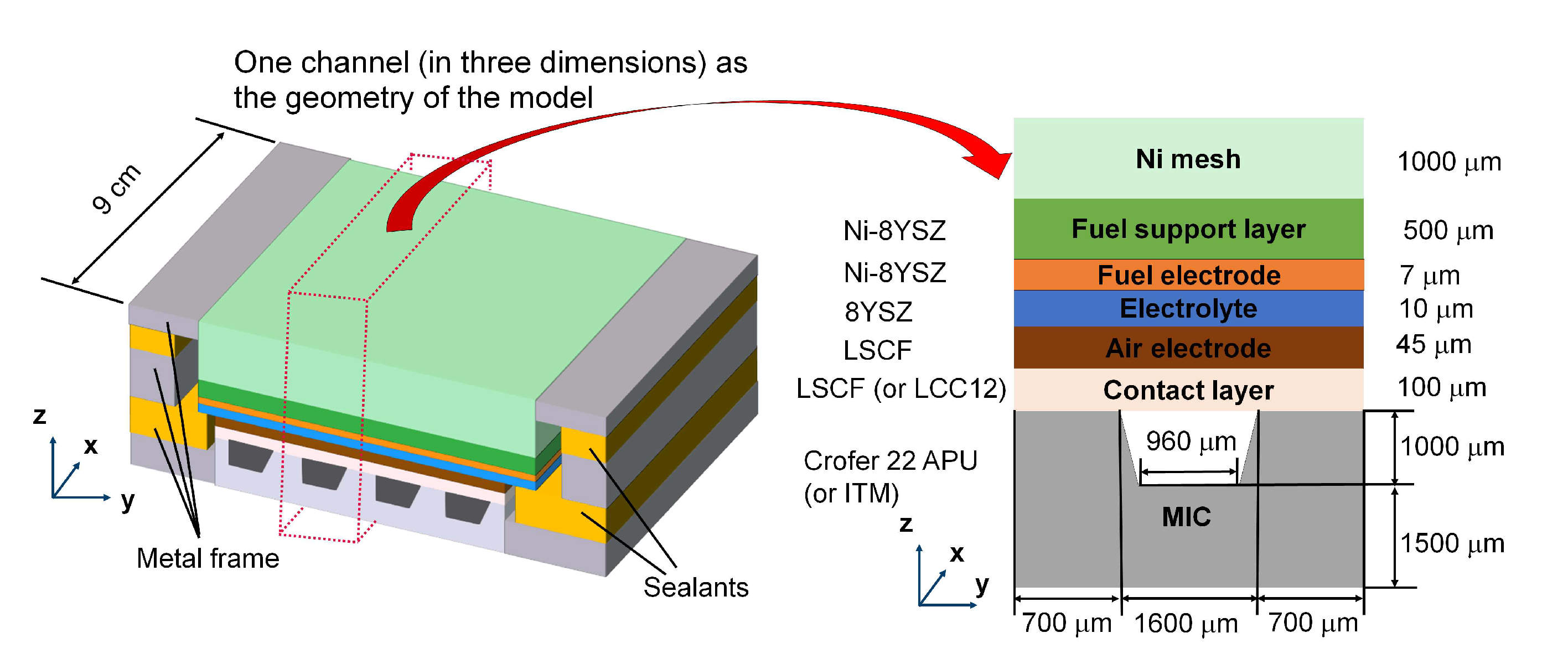
Figure 2.
Schematic of the ultra-thin film resistance model. To more clearly illustrate the model, only the contact layer and MIC are shown in the figure.
Figure 2.
Schematic of the ultra-thin film resistance model. To more clearly illustrate the model, only the contact layer and MIC are shown in the figure.
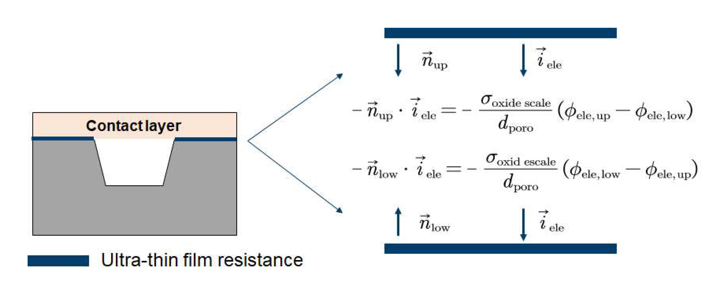
Figure 3.
The mesh of the model.
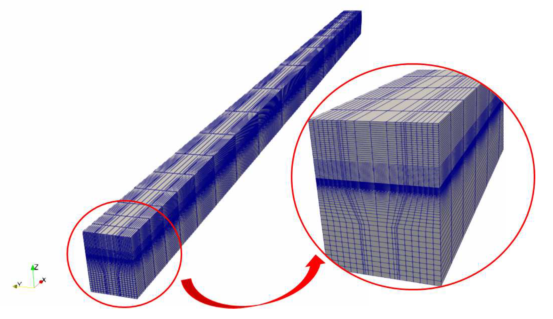
Figure 4.
Validation of I-V curves of (a) F1002-97, 12% humidified fuel, SOFC, (b) F1004-67, 20% humidified fuel, SOFC and (c) F1004-115, 50% humidified fuel, SOFC and SOEC.
Figure 4.
Validation of I-V curves of (a) F1002-97, 12% humidified fuel, SOFC, (b) F1004-67, 20% humidified fuel, SOFC and (c) F1004-115, 50% humidified fuel, SOFC and SOEC.
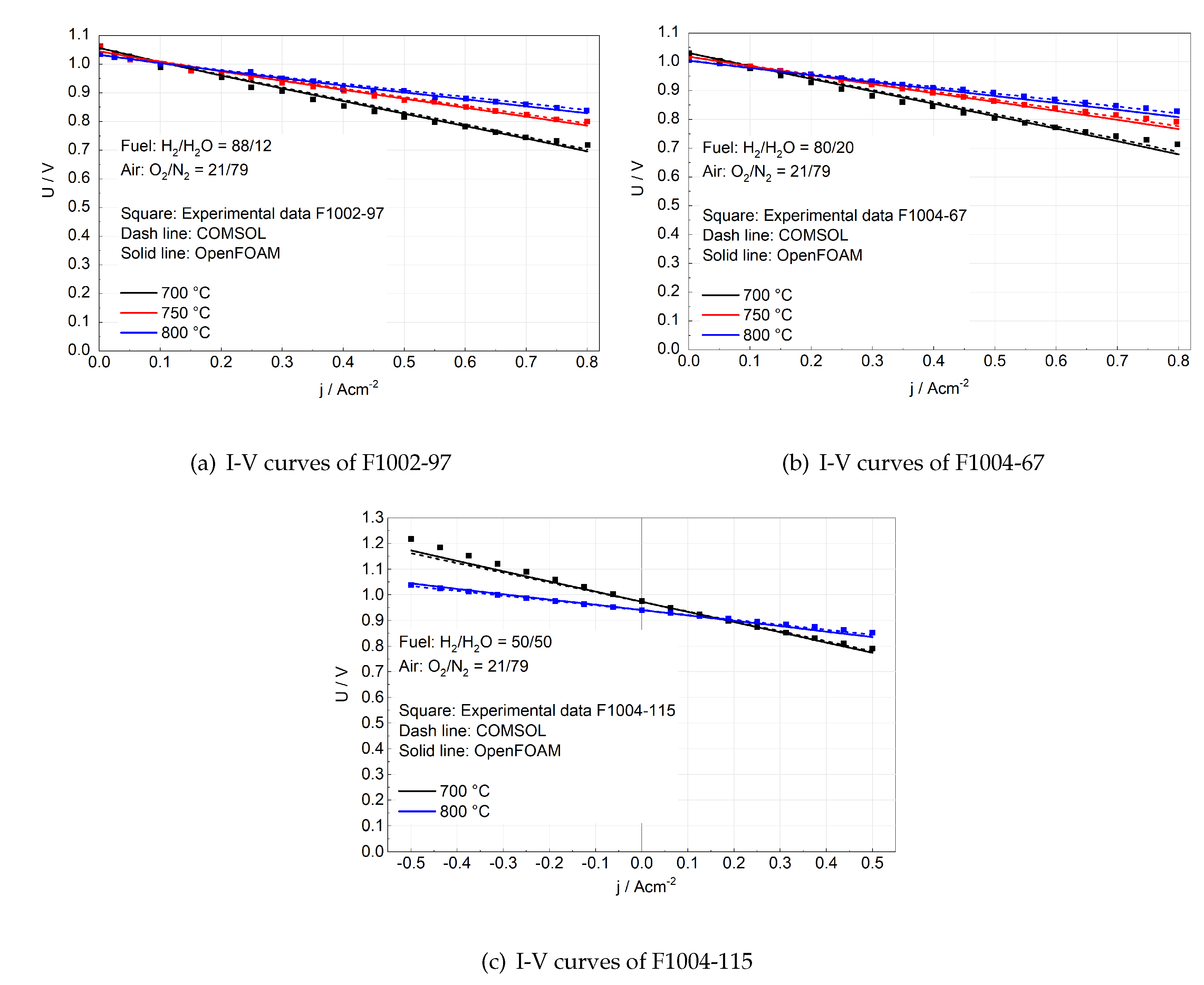
Figure 5.
Validation of MIC oxidation model. The experimental data are taken from TGA on DTU SOC stacks [45]. Crofer 22 APU was used as the MIC. One stack was operated without coatings while another stack was coated with 15 µm LSM, whose porosity was measured as 0.3 after 4000 h of operation [45].
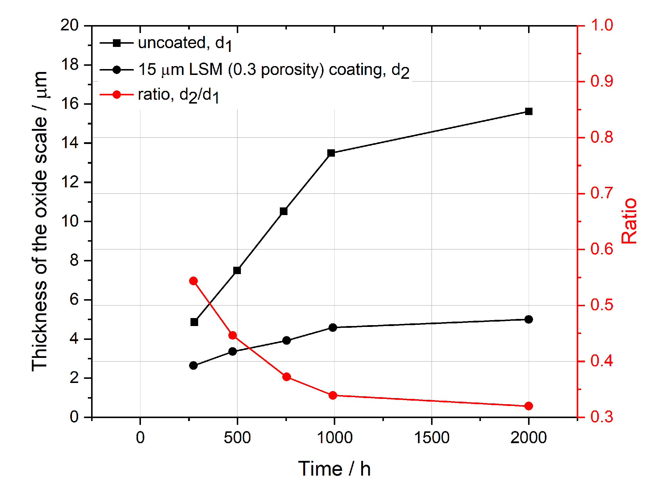
Figure 6.
Validation of MIC oxidation model. The experimental data (21 data pints for F1002-97 and 29 data points for F1002-95) are taken from a scanning electron microscope (SEM) on FZJ SOC stacks after they were shut down [56,57].
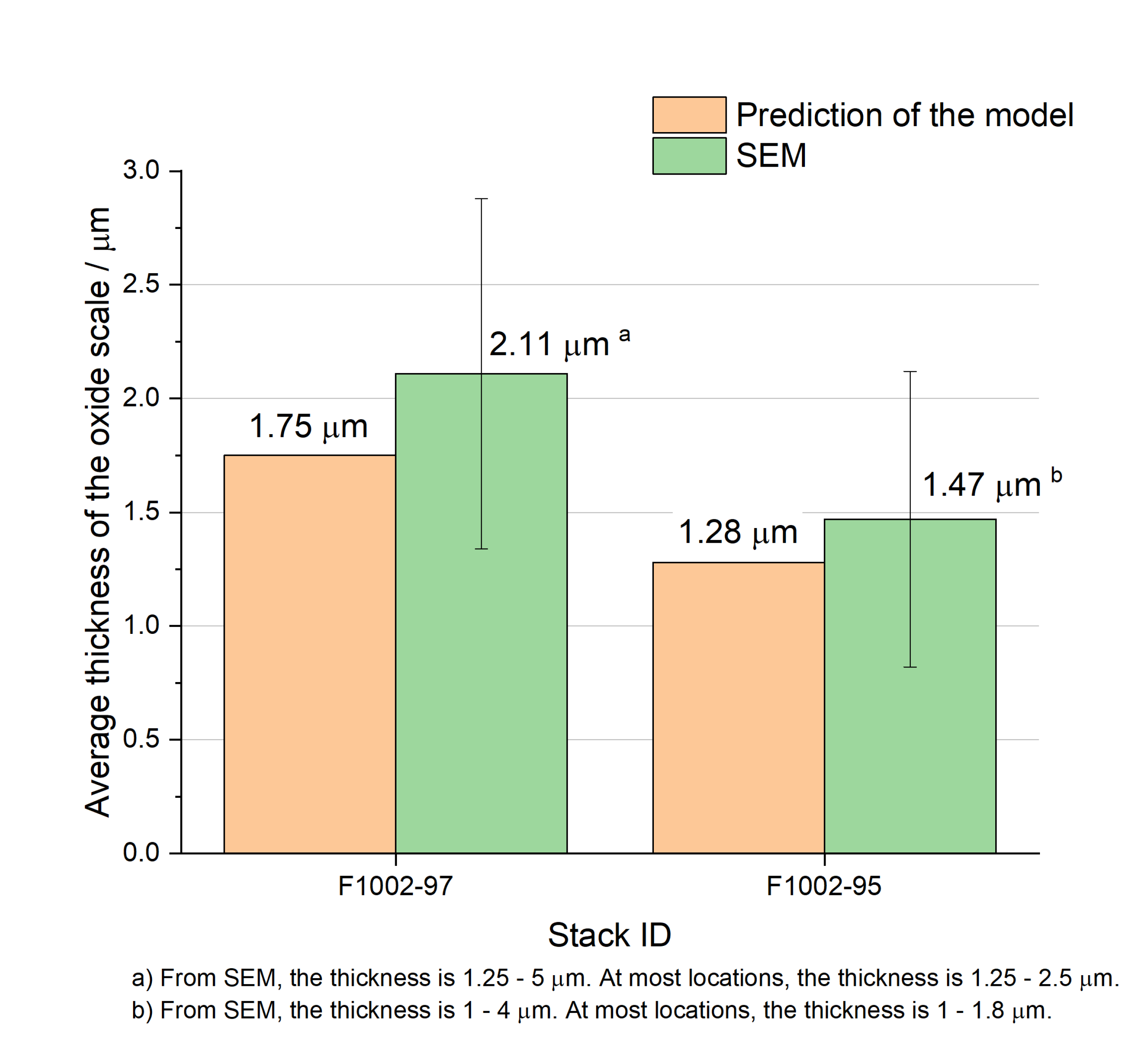
Figure 7.
Spatial distribution of mole fractions in the x-y plane of the fuel electrode and the air electrode. The simulation is the electrolysis operation of F1004-115, where fuel flows towards the x-coordinate direction and air flows against the x-coordinate. The geometry is scaled by the transformation vector (x, y, z) = (1, 20, 1)
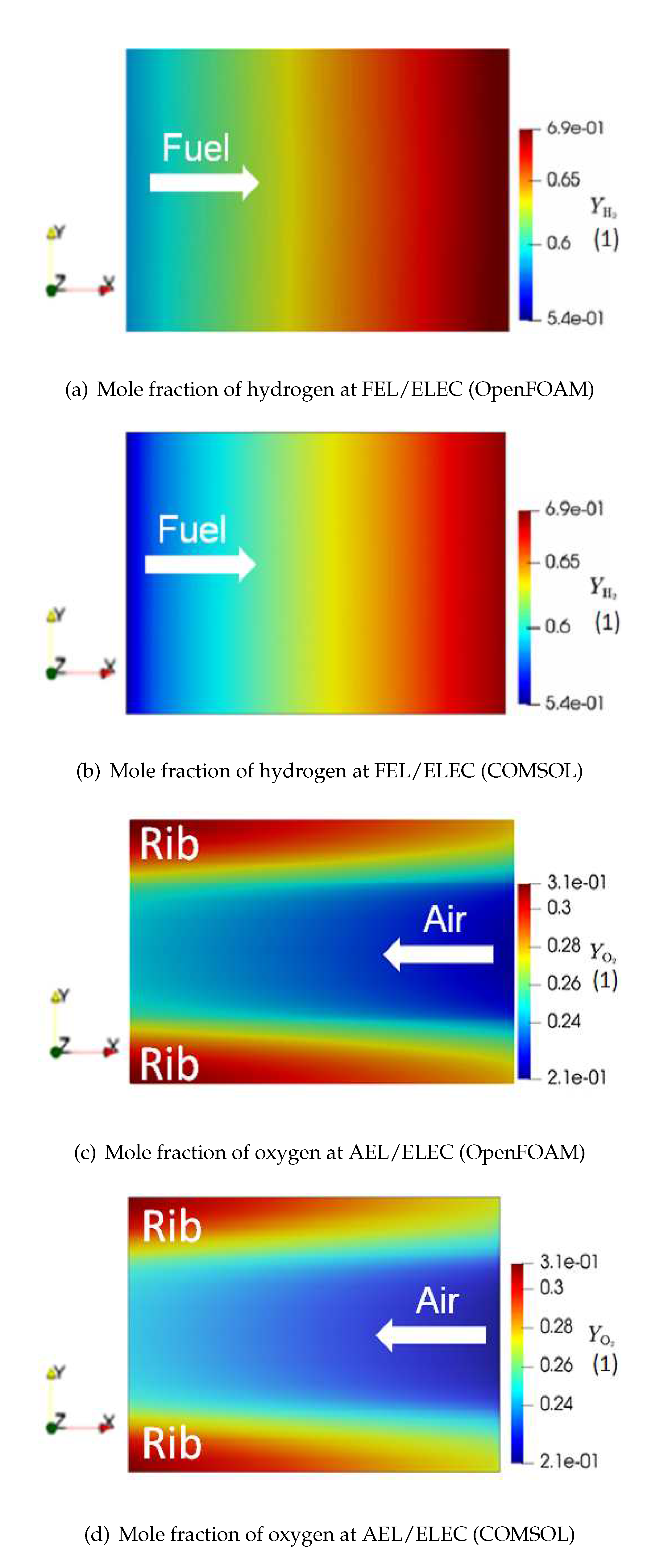
Figure 8.
Spatial distribution of overpotential on the outer surface of the fuel electrode and the air electrode in the x-z plane (see geometry in Figure 1). The simulation is the electrolysis operation of F1004-115, where fuel flows towards the x-coordinate direction and air flows against the x-coordinate. The geometry is scaled by the transformation vector (x, y, z) = (0.05, 1, 60)
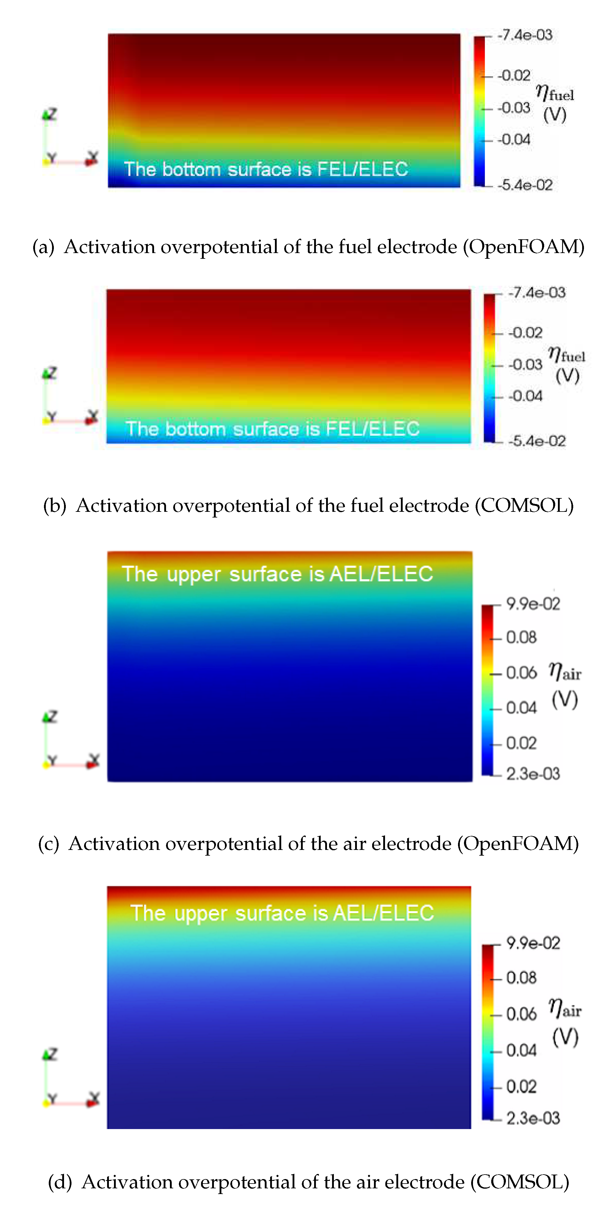
Figure 9.
Simulation of the stack voltage evolution of F1002-97 with time. Only MIC oxidation is considered as the degradation. The inserted figures are the distribution of the electronic potential across the contact layer and the MIC.
Figure 9.
Simulation of the stack voltage evolution of F1002-97 with time. Only MIC oxidation is considered as the degradation. The inserted figures are the distribution of the electronic potential across the contact layer and the MIC.
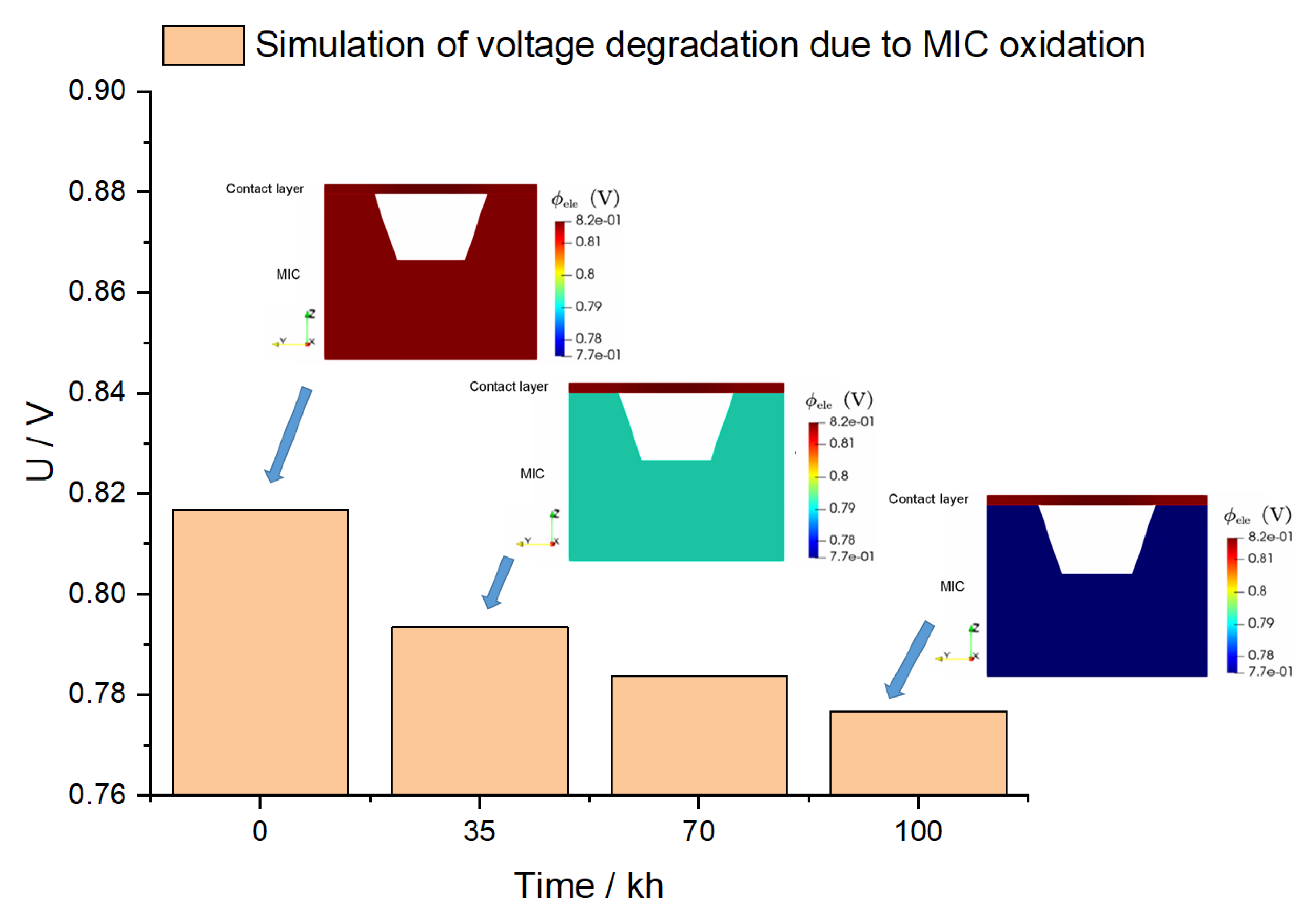
Figure 10.
Comparison of the experimental data and simualtion results of F1002-97: (a) is the voltage evolution only due to MIC oxidation and (b) is the share of voltage degradation rate caused by MIC oxidation. A sudden increase is observed in (b), because the total degradation rate is decreased from 7.3 mV/kh to 1.6 mV/kh at 40 kh.
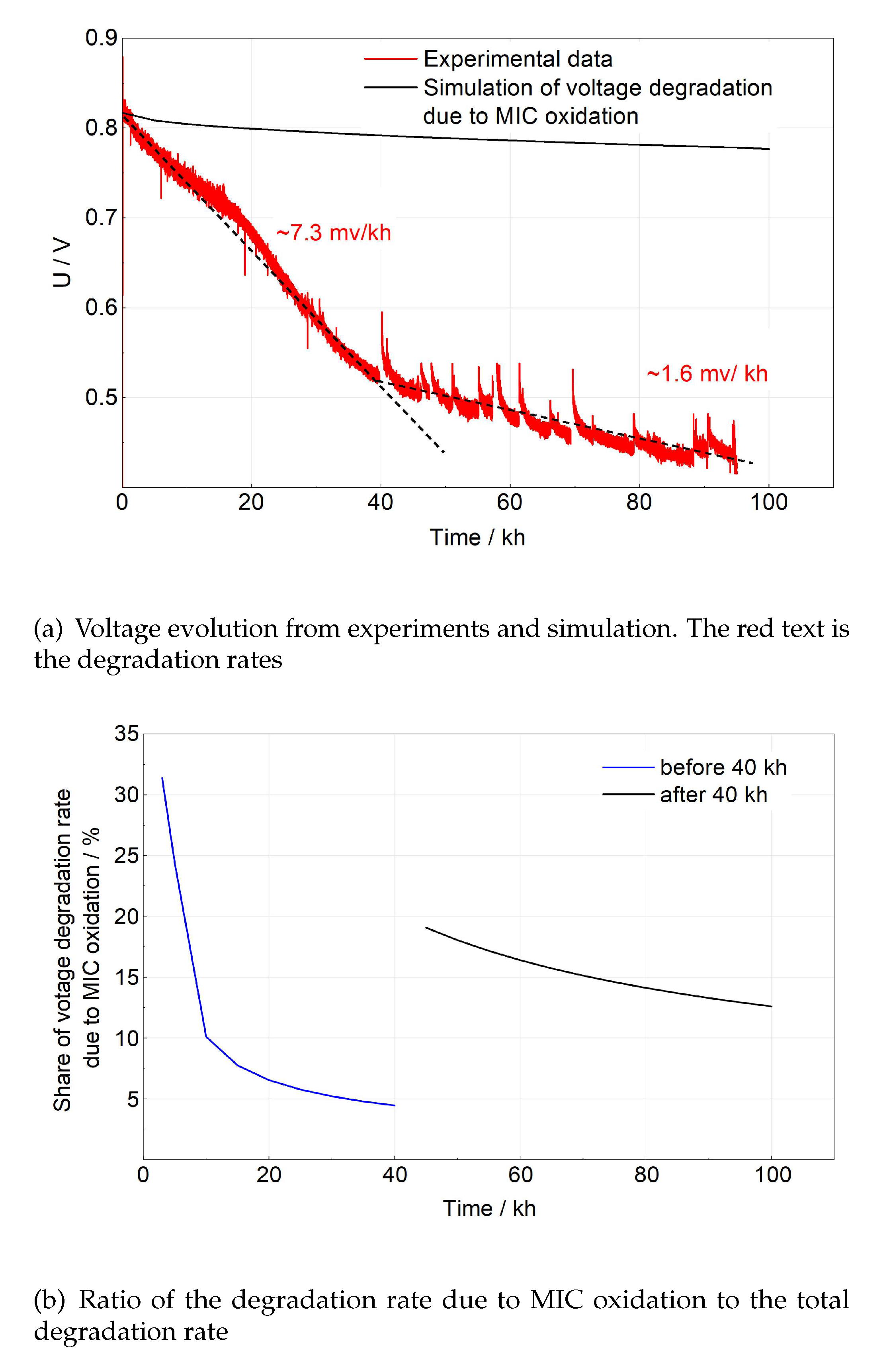
Table 1.
Summary of main models used in this work.
| Physical phenomenon | Domain or surface | Main equation |
|---|---|---|
| Electrochemical reaction | Electrodes | Chang-Jaffe kinetic |
| Momentum transfer | Channels | Navier–Stokes equations |
| Porous medium | Darcy-Forchheimer equation | |
| Heat transfer | All domains | Constant temperature assumption |
| Mass transport | Channels and porous medium | Fick’s law |
| MIC oxidation | Rib surface | Parabolic law |
Disclaimer/Publisher’s Note: The statements, opinions and data contained in all publications are solely those of the individual author(s) and contributor(s) and not of MDPI and/or the editor(s). MDPI and/or the editor(s) disclaim responsibility for any injury to people or property resulting from any ideas, methods, instructions or products referred to in the content. |
© 2023 by the authors. Licensee MDPI, Basel, Switzerland. This article is an open access article distributed under the terms and conditions of the Creative Commons Attribution (CC BY) license (http://creativecommons.org/licenses/by/4.0/).
Copyright: This open access article is published under a Creative Commons CC BY 4.0 license, which permit the free download, distribution, and reuse, provided that the author and preprint are cited in any reuse.


