
Submitted:
08 February 2023
Posted:
09 February 2023
You are already at the latest version
Abstract
Symbolic pole/zero analysis is an important step when designing an analog operational amplifier. Generally, a simplified symbolic analysis of analog circuits suffers from NP-hardness, i.e., an exponential growth of the number of symbolic terms of the transfer function with the circuit size. In this study, we present a mathematical model combined with a heuristic-metaheuristic solution method for the symbolic pole/zero simplification in operational transconductance amplifiers (OTA). At first, the circuit is symbolically solved and an improved root splitting method is applied to extract symbolic poles/zeroes from the exact expanded transfer function. Then, a hybrid algorithm based on heuristic information and a metaheuristic technique using simulated annealing is performed for the simplification of the derived symbolic pole/zero expressions. The developed method has been tested on three analog OTAs. The obtained results show the effectiveness of the proposed method to achieve accurate simplified symbolic pole/zero expressions with the least complexity.
Keywords:
operational transconductance amplifiers
; symbolic circuit analysis
; pole/zero extraction
; root splitting
; simplification
; simulated annealing
1. Introduction
Recently, multi-stage cascode operational transconductance amplifiers (OTAs) have become widely applied in modern microelectronics, as OTAs can provide large output swing and high gain with very low overdrive voltage [1,2,3,4]. However, as each stage has its own poles and zeroes, the bandwidth may be reduced. In addition to the poles and zeros of each additional stage, the compensated capacitors may add some extra poles and zeroes. One of the main challenges in the design of multi-stage OTAs is to devise the frequency compensation procedure capable of providing wide bandwidth and high gain with appropriate stability margins. In this regard, a simplified extraction of symbolic poles and zeros can give better analytical expressions and assist designers to make a straight decision when designing an OTA and a frequency compensation circuit [5].
Generally, an exact symbolic analysis of OTAs is error-prone and time-consuming if it is done by hand, even for circuits with a small number of components [6]. In this regard, a computer-aided automatic symbolic resolution can be helpful by solving the circuit equations by mathematical solvers such as Cramer’s rule [7]. It can be done by exploiting symbolic analysis solvers embedded via software tools such as MATLAB, GNU Octave, and MAPLE [8]. The main drawback of a symbolic analysis is that the derived symbolic equations are very complex and they cannot be effective to guide the circuit designer [9]. Although various symbolic simplification techniques have been introduced, simplified expressions are not provided in factorization form, and thus, it is very hard to evaluate the effects of roots on the behavior of the circuit.
Although the existing symbolic pole/zero analysis methods [8,9,10,11,12,13,14,15,16,17,18,19,20,21] incorporate some types of approximations during the calculation of transfer function, they suffer from some drawbacks which limit their effectiveness for real-world OTAs: First, these methods are inefficient in the case of overall generated error rates in terms of magnitude, phase, poles, and zeros. Second, the correlation between eliminated terms in different polynomials is not under effective consideration in polynomial-oriented methods. Third, pole/zero displacements due to approximations are not under control. Fourth, those closely spaced pole/zero pairs may be disappeared due to a magnitude/phase-oriented approximation, which can generate high error rates at the points other than the nominal ones.
In this study, we present a simplified symbolic pole/zero extraction technique to overcome the mentioned drawbacks. The method is based on the root splitting technique [11] and a simulated annealing (SA) algorithm [22]. We introduce an enhanced root splitting (named ERS) for the symbolic pole/zero extraction from the exact transfer function. In this method, pole/zero displacements cannot exceed a pre-specified threshold. Then, we apply a combined heuristic-metaheuristic pole/zero simplification based on SA (named PZSA) to simplify the derived pole/zero expressions. The key contributions outlined in this study can be mentioned as follows:
- Introducing a combined mathematical-heuristic-metaheuristic technique for the extraction and simplification of symbolic poles and zeros in OTAs.
- Proposing an enhanced root splitting technique, named ERS, to accurately extract the exact pole/zero expressions.
- Presenting a combined heuristic-metaheuristic algorithm for symbolic pole/zero simplification (named PZSA) utilizing heuristic knowledge available in the circuit model and simulated annealing.
- Programming of the proposed method in a MATLAB m-file, wherein simplified pole/zero equations are automatically generated from the circuit netlist.
- Successfully driving symbolic pole/zero expressions for three OTAs.
The rest of this study is organized as follows: In Section 2, the existing literature for a symbolic simplification and symbolic pole/zero extraction are reviewed. In Section 3, the proposed methodology is presented with details, and then, the developed method in MATLAB is evaluated in Section 4. Finally, in Section 5, some concluding remarks as well as future directions are addressed.
2. Literature Review
Over the recent years, along with the increasing advancement and development in analog circuit design, various symbolic simplification techniques and symbolic pole/zero extraction methods have been proposed. According to the existing literature, these methods are described in the following.
2.1. Symbolic Simplification Techniques
The symbolic analysis of OTAs suffers from NP-hardness [7]. For instance, the μA741 amplifier has about 1034 terms within its voltage transfer function [23]. Therefore, symbolic analysis tools must rely on the simplification techniques to tackle with the complexities and hardnesses of real-world circuits. Based on the step in which a simplification is done, simplification algorithms can be categorized into SAG (simplification-after-generation), SDG (simplification-during-generation), and SBG (simplification-before-generation) [24]. It is worth noting that the PZSA algorithm in this study is a SAG technique. A SAG is performed once the symbolic circuit analysis is done and consequently the exact symbolic expressions have been obtained so that simplified functions can be constructed from some terms of the exact expressions. In the following, we discuss the details of the SAG technique, which is used in the proposed method.
The small-signal transfer function of a linear or linearized circuit can be represented as a function of the frequency and the circuit parameters as follows:
Each polynomial or is a sum-of-product (SOP) of which is expressed as , where is -th polynomial within the circuit transfer function comprising terms.
The simplification method in [25] finds the largest term in terms of the magnitude, , for the polynomial . Then, all other terms within the polynomial are taken one by one. The condition for which the term can be discarded from the polynomial , is . Here, (0 < < 1) is a user-specified threshold to limit the maximum error. The main drawback is that the error may be accumulated. To overcome this drawback, the reported criterion in [26] sorts the terms within based on their magnitude obtained in the nominal point. Afterwards, terms with the least accumulated magnitude are discarded from the polynomial, if the error is below . The condition on the terms for which they could be discarded, can be expressed as follows:
Although this method achieves more accurate expressions at the nominal point, it may cause significant errors for other values of the parameters. To avoid an elimination of the mutually canceling terms, the method in [27] presented an enhanced condition for which the terms with the least magnitude can be discarded if:
In the above-mentioned techniques, the maximum error is limited for each polynomial. However, the obtained error in the poles and zeroes is not under consideration. If the same error drives in all polynomials, no pole and/or zero displacement can be observed [28]. To overcome this drawback, an adaptive can be used, in which, erm deletion is done step by step while displacements in poles and zeros are monitored at every step, so that the term pruning procedure would be finished if the obtained displacements are beyond a pre-determined threshold [26].
Recently, various swarm and evolutionary metaheuristic algorithms [29,30,31,32,33,34] have been applied for the simplified symbolic analysis of OTAs. In these techniques, different criteria such as the magnitude error, phase error, and pole/zero displacements, have been used to evaluate feasible solutions generated by the metaheuristic algorithm. Although these methods achieve a low mean error rate, the worst cases of the displacements in the poles and zeroes are not accurately under consideration. The common drawback of the existing techniques is that the simplified function is achieved in either expanded or nested form. In other words, the transfer function is not derived in a factorization form which makes it hard to evaluate the contribution of roots.
2.2. Symbolic Pole/Zero Extraction Techniques
The symbolic pole/zero analysis also suffers from the NP-hardness, even worse, as some operations between the polynomials have to be performed. Generally, a direct calculation of the roots from the expanded transfer functions yields very complex results for polynomials with degrees larger than two [7]. Since the numerator and denominator of a transfer function in practical OTAs have generally degrees much larger than two, it is rarely possible to mathematically find the exact symbolic pole/zero expressions [10].
In the following, the existing pole/zero extraction methods including root spitting, time-constant analysis, and eigenvalue analysis are discussed. Root splitting [11] is one of the well-known root extraction techniques. It extracts poles assuming them to be reciprocally dominant. By factorization, the denominator of the exact function in Eq. (1) can be re-written as a function of the poles as follows:
It follows from Eq. (1) that
Therefore, assuming to be the dominant pole within the denominator, the first pole can be approximately expressed as:
Consequently, with a similar approach, considering to dominate the other poles, can be given by the negative quotient of the two consecutive coefficients and [8]. Similar argumentations can be done to calculate simplified zeroes from the numerator of the transfer function. The root splitting method is not appropriate for manual pole/zero calculations (hand-and-paper analysis), as some estimations and simplifications should be developed to allow the circuit designer in extracting approximate dominant poles and zeroes manually. The most popular approach of such techniques is the time-constant method [10,12,13,14], which is expressed in Eq. (7), where can be achieved by multiplying the resistance to the capacitance .
This technique is error-prone, as there is no information about the accuracy of the obtained symbolic results. Moreover, zeroes and higher-order poles cannot be determined by this approach, at all. A more general approach in this context was reported in [13] which has also the ability to extract the higher-order poles. This method is based on open-circuits and short-circuits analysis to calculate the time constants of the circuit.
There are also some pole/zero extraction methods on the basis of the solution derived by the eigenvalue problem. A positive feature of these methods is that the simplification is no longer driven by magnitude and phase errors but by the pole/zero position, allowing an improved error control. For example, a modified Signal-Flow Graph (named MSFG) has been recently developed to represent the equivalences between the system and SPICE outcomes of static nonlinear OTAs [15]. In this method, the circuit is firstly converted into an MSFG, and then, the graph would be simplified in particular polynomials by minimizing the MSFGs. In [19], the implementation of some simplification procedures during the eigenvalue computation via a symbolic LR algorithm was addressed, in which the LR method is applied to compute the reduced matrix corresponding to the eigenvalue cluster. This technique is followed in [20] by an algorithm to reduce the circuit matrix into a row echelon format. After the determination of the symbolic state matrix, the approximated poles and zeroes are achieved using the LR algorithm.
The main drawback of the existing symbolic pole/zero analysis methods is that the simplified expressions of poles and zeroes are not so compact as no SAG is applied on the final expressions. So, in this study, we utilize a combined heuristic-metaheuristic SAG algorithm to ensure obtaining the simplified symbolic pole/zero expressions with the least achievable complexity.
3. Proposed Method
The list of indices, sets, and parameters which are used in the following equations in this section are provided in Table 1. The overall flowchart of the proposed symbolic pole/zero analysis can be seen in Figure 1. As a summary, the main steps of the methodology can be summarized as follows:
- 1)
- Input circuit netlist is loaded as a text file (in .txt format).
- 2)
- All transistors are replaced via proper small-signal modeling.
- 3)
- The symbolic circuit is solved via a modified nodal analysis (MNA).
- 4)
- The exact transfer function (TF) is achieved in the expanded symbolic form.
- 5)
- Exact expressions of poles and zeroes are derived using ERS.
- 6)
- Numerical results of the exact symbolic pole/zero expressions are stored.
- 7)
- A heuristic algorithm is performed to generate a near-optimal solution utilizing the circuit-based knowledge available in the exact poles and zeroes.
- 8)
- SA is performed to improve further the quality of the heuristic solution, to generate the final simplified symbolic pole/zero expressions.
- 9)
- Numerical results of the obtained simplified symbolic pole/zero expressions are calculated.
- 10)
- Numerical results of the exact and simplified poles/zeros are compared against HSPICE and other simplification algorithms.
3.1. Pole/Zero Extraction via ERS
After the netlist pre-processing, the circuit is solved using MNA [7], and consequently, the exact symbolic TF is achieved in expanded form. Then, the obtained exact pole/zero expressions are approximately calculated using the proposed ERS method which is an enhanced version of the traditional RA algorithm. Generally, an expanded TF could be converted into the factorized form according to Eq. (8), where is a function of (real or complex conjugate) zeroes , , …, , and is a function of (real or complex conjugate) poles , , …, .
In the ERS algorithm, only poles and zeroes located in the interval [ would be extracted, where and are the minimum and maximum user-specified frequency for the pole/zero extraction, respectively. If the frequency range has not been specified by the user, it is considered as default range of [, where is the frequency of unity-gain of the exact expression in the nominal point. In the following, the pole extraction procedure for is described. By comparing Eqs. (1) and (8), can be calculated as:
Typically, a single real pole is dominant in OTAs. Assuming to be dominant and all other poles to be located at much higher frequencies, i.e., , the first pole can be splitted, and thus, can be approximately written as:
By equating the coefficients of in Eq. (10) to those in Eq. (9), the dominant real pole can be approximated given as:
Consequently, by assuming the condition in Eq. (12), we can simplify the rightmost expression of Eq. (11) as Eq. (13). By equating the coefficients of Eq. (13) to the same coefficients in Eq. (9), the parameters can be calculated as Eq. (14).
and thus, the leftmost expression in Eq. (10) can be expressed as:
The circumstances of coefficients in the original denominator , for which Eq. (15) is valid, are:
Equation (15) shows that can be simplified into a product of a first-order polynomial (i.e., first dominant pole) and a high-order polynomial corresponding to other high-frequency poles. In a more general case, assuming the first poles () to be successively dominant in pairs (i.e., dominates , dominates , and so on, dominates ), can be approximated as follows:
By similar approximations as done in the previous case, can be simplified according to:
By equating the coefficients of Eq. (18) and Eq. (9), the first poles are derived as Eq. (19). Also, the parameters can be expressed as Eq. (20). So, can be simplified into the multiplication of +1 polynomials: first-order polynomials (representing the first poles) and a high-order polynomial, as Eq. (21). The conditions on coefficients of , for which Eq. (21) is valid, can be expressed as Eq. (22).
In the general case, let us extend the above formulations for the case that all the poles are dominant reciprocally, in which, can be approximated as follows:
Under the assumption that all poles are dominant in pairs (i.e., dominates , dominates , and so on), the following conditions are satisfied:
Therefore, the rightmost expression in Eq. (24) can be approximated as Eq. (25). By equating coefficients of Eq. (25) and Eq. (10), in Eq. (25) can be approximately expressed as Eq. (26), where each pole can be calculated according to Eq. (27).
The interesting feature is that all poles are derived from coefficients of the denominator of the transfer function. The above formulations are under the assumption that all poles are real. In other words, the approach fails for closely spaced or complex conjugate poles. Therefore, the method should be extended for the cases in which two consecutive poles are located in a cluster. Assuming that and are a pair of poles (real or conjugate), they are remained split off in the expression and can be expressed via a second-order polynomial , where and can be calculated as follows:
The condition for which the poles and are real, is . If the condition has been satisfied, the real poles and can be expressed as Eq. (29). Otherwise, these poles can be represented as complex conjugate poles according to Eq. (30).
It should be emphasized that all above formulations could be used for the extraction of simplified zeroes from the numerator of the expanded TF. In ERS, the pole (or zero ) can be splitted by means of Eq. (26), if the conditions in Eqs. (31) and (32) are met, where () is the absolute of the numerical value of -th pole (-th zero) extracted via the ERS method, and () is the absolute of the -th pole (-th zero) of the exact function of Eq. (1), which are numerically achieved by the calculation of the roots of the transfer function. () is the set of poles (zeroes) which are in the range of the interval [. Also, is a pre-determined constant to specify the maximum allowable root displacement (in %) for the each ERS-root, compared with the exact one.
The ERS pole/zero extraction method comprises evaluation and extraction steps. In the evaluation step, all poles and zeros within the interval [ are assumed to be reciprocally dominant, and thus, their ERS values are numerically obtained according to Eq. (26). In the extraction step, the conditions of Eqs. (31) and (32) are checked for all extracted poles and zeroes. Then, each pole (zero) which has satisfied the mentioned condition, can be symbolically extracted according to Eq. (26). On the other hand, the pair of real or complex conjugate poles (zeros) remained split off and the condition is checked for them. If the condition has been satisfied, the poles (zeros) are a pair of real poles (zeroes) and can be calculated by Eq. (29). Otherwise, they are considered as complex conjugate poles (zeroes) which are extracted by means of Eq. (30).
3.2. Pole/Zero Simplification via PZSA
The extracted symbolic pole/zero expressions cannot give an analytical information about the circuit behavior, due to their high complexity. So, a pole/zero simplification based on PZSA is used to simplify the exact pole/zero expressions. SA is a single-solution metaheuristic inspired from the metallurgy annealing, which involves heating and then slowly cooling of the material to reduce its defects [22]. Generally, SA starts its search from a fully random solution, and then, iteratively updates the solution until arriving at the stopping criterion [35]. However, to improve the quality and speed of the search process in SA, we utilize the knowledge from the exact circuit expressions as heuristic information to guide the SA algorithm by starting from a near-optimal solution. After generating the initial solution using the heuristic algorithm, SA is performed for improving further the quality of the solution using local search operators in an iterative procedure. In the following, the main steps of the PZSA algorithm are described.
3.2.1. Solution Encoding/Decoding
A possible solution to the pole/zero simplification problem, as shown in Figure 2, is a binary vector of length , where is the number of original terms, which can be calculated as follows:
where , , and are the number of symbolic terms within the DC-gain , the -th zero, and the -th pole, respectively.
3.2.2. Generation of the Initial Solution
To construct the initial solution of SA, we utilize heuristic information available in the circuit via a ranking algorithm (RA). It not only improves the convergence speed of SA as it utilizes a near-optimal solution, but also can effectively enhance the quality of the final solution. The RA comprises an evaluation step and a selection step. In the first step, each term is eliminated, and accordingly, the generated error rate is measured and stored. After the evaluation of all terms, they are sorted in a list from the best to the worst. In the selection phase, an empty solution is considered, and then, the terms within the list are added one by one until all constraints have been satisfied.
3.2.3. Objective Function Evaluation
To justify the performance of each solution, an objective function is formulated to compare the simplified pole/zero expressions with the exact ones in terms of the number of terms and mean pole/zero displacements. Moreover, each pole/zero displacement should not exceed the user-specified margin . The objective function is expressed as a weighted average of the minimization of the number of terms and mean pole/zero displacements. These two conflict objectives are merged into a single formula as Eq. (34), where pole/zero displacements are calculated according to Eqs. (35) and (36), respectively.
subject to:
In Eq. (34), and are constants (+=1) which specify the relative impacts of the two objectives. As the worst-case pole/zero displacement is limited by Eqs. (37) and (38), should be set much larger than to ensure achieving the simplest expressions.
3.2.4. Generation of a New Solution
In each iteration, a neighbor solution, , is constructed in the vicinity of the current solution, . We adopt a swap (Figure 3) and an exchange (Figure 4) operators as neighborhood search strategies in SA. To generate a new solution, an operator is randomly selected with the probability of 50%, and then, it operates on the solution .
3.2.5. Acceptance Rule Checking
In each iteration, if , the new solution is accepted. Otherwise, if , the new solution (worse solution) has a chance to be accepted with the probability of , which can be calculated according to the current temperature and the differences between the objective values of the two solutions as follows:
where is considered to be linearly decreased during the execution of SA from (initial temperature) to (final temperature), as follows:
4. Performance Evaluation
All simulations were carried out on a PC with 2.6 GHz CPU, 6 GB RAM. The presented tool has been successfully coded in an m-file - MATLAB R2020b running on Windows 10. All MOS transistors are modelled via a small-signal which can be seen in Figure 5. The parameters of the proposed tool have been set as provided in Table 2. As can be seen, has been set to 10 %, and thus, the poles and zeroes with no more than 10 % displacement can be simplified via first-order polynomials, while the other poles and zeroes are expressed via second-order polynomials. To justify the proposed methodology, we compare it against a time-constant approach [13], an eigenvalue technique [15], and an evolutionary-based algorithm using a genetic algorithm [34].
4.1. Results for a Three-Stage Amplifier in the RCgm Model (Circuit 1)
The block diagram of a three-stage compensation OTA can be shown in Figure 6. The circuit is described by the equivalent RCgm model. By using MNA, the exact expanded TF has been derived as follows:
The exact TF comprises 40 terms. By performing the simplification algorithm in [34], the simplified expanded TF with 10 terms has been obtained according to Eq. (42). The expanded TF even in the simplified form, cannot give effective insights for the designer to evaluate the positions of poles and zeroes. However, by performing PZSA, three poles and two zeroes can be achieved as Eqs. (43)-(47).
The comparison of the different methods according to the number of simplified terms within the simplified poles/zeroes can be summarized in Table 3. Moreover, the numerical results of the different methods are provided in Table 4, wherein the last four rows illustrate the error of the simplified equations when compared to the exact expressions.
4.2. Results for a Two-Stage Miller Compensated Amplifier (Circuit 2)
The second circuit is a folded cascode two-stage OTA with the compensation described by MOS transistors, as shown in Figure 7. The exact expanded TF obtained by MNA contains 134 symbolic terms.
By performing the simplification method in [34], the simplified TF has been obtained according to Eq. (48). By utilizing PZSA on Eq. (48), two simplified poles and one zero have been obtained as Eqs. (49)-(51), respectively. Similar to Circuit 1, the comparison of the number of simplified terms and the numerical results are summarized in Table 5 and Table 6, respectively.
4.3. Results for a Three-Stage Amplifier in Transistor Model (Circuit 3)
The last circuit is a transistor-level three-stage amplifier with miller compensation, as shown in Figure 8. The exact expanded TF of this circuit contains 1320 symbolic terms. Considering the approximation algorithm in [34], the simplified expanded TF with 18 symbolic terms has been obtained as Eq. (52). By applying PZSA, three simplified poles and two zeroes have been obtained according to Eqs. (53)-(57). The number of simplified terms and numerical results of the different algorithms are summarized in Table 7 and Table 8, respectively.
4.4. Discussion
Generally, in the reported simplified symbolic pole/zero expressions, three types of errors can be observed:
- Error-1: the first type of error may occur by comparing HSPICE with the exact expanded TF achieved by MNA. This error may be observed for OTAs described in the transistor level, as HSPICE considers more accurate small-signal modeling for transistors than the simple model in our program (see Figure 5).
- Error-2: the second type of error may be observed when comparing the exact TF with the exact extracted poles/zeroes, because of the simplifications done by the root extraction process via the ERS method.
- Error-3: the third error may occur between exact pole/zero expressions and the simplified ones, due to the simplifications done by PZSA.
As mentioned above, Error-1 is inevitable in symbolic analysis which is observed in all symbolic tools. However, Error-2 and Error-3 may occur because of our method in the pole/zero extraction and simplification, respectively. For this purpose, in the results of Tables 4, 6, and 8, we have reported these errors for each algorithm by comparing them with the exact expanded TF. So, the numerical results of the poles and zeroes in the exact TF were considered as reference to justify the performance of the different techniques.
5. Conclusion
In this paper, we have presented a mathematical modeling following by a combined heuristic-metaheuristic solution for the symbolic pole/zero simplification in OTAs. In the proposed method, at first, a mathematical model is presented for the extraction of exact poles and zeroes from the original expanded expression of OTA. Then, an ensemble heuristic-metaheuristic approach is proposed to obtain the simplest symbolic pole/zero equations from the exact ones. In the proposed ensemble method, a near-optimal solution is firstly constructed by means of the knowledge-based heuristic information available in the circuit model, and then, a metaheuristic algorithm based on simulated annealing is performed to obtain the simplest pole/zero expressions with the best achievable quality. The proposed tool has been coded in an m-file of MATLAB to extract simplified pole/zero equations directly from the circuit netlist. Simulations on three OTAs have demonstrated the effectiveness and superiority of the proposed technique against the existing algorithms in the literature. Beside the advantages of the proposed technique, it relies on a nominal point for the circuit parameters. As a future work, it can be extended to deal with the uncertainties of the parameters by the help of Data Mining, Monte Carlo simulation, fuzzy logic, etc. Moreover, the proposed SAG technique can be hybridized with SBG and SDG methods to deal with larger OTAs.
Author Contributions
Conceptualization, N.B., H.Y. and M.S.; methodology, M.S.; software, M.S.; validation, M.S. and F.W; investigation, M.S.; data curation, N.B, H.Y. and M.S.; resources, N.B. and H.Y.; writing—original draft preparation, N.B. and M.S.; writing—review and editing, M.S., H.Y. and F.W.; visualization, N.B.; formal analysis, F.W.; supervision, M.S. and F.W. All authors have read and agreed to the published version of the manuscript.
Funding
This research received no external funding.
Institutional Review Board Statement
Not applicable.
Informed Consent Statement
Not applicable.
Data Availability Statement
The data used in the study is available with the authors and can be shared upon reasonable requests.
Conflicts of Interest
The authors declare no conflict of interest.
References
- Riad, J.; Soto-Aguilar, S.; Estrada-López, J.J.; Moreira-Tamayo, O.; Sánchez-Sinencio, E. Design Trade-Offs in Common-Mode Feedback Implementations for Highly Linear Three-Stage Operational Transconductance Amplifiers. Electronics 2021, 10, 991. [Google Scholar] [CrossRef]
- Rodovalho, L.H.; Toledo, P.; Mir, F.; Ebrahimi, F. Hybrid Inverter-Based Fully Differential Operational Transconductance Amplifiers. Chips 2023, 2, 1–19. [Google Scholar] [CrossRef]
- Akbari, M.; Shokouhifar, M.; Hashemipour, O.; Jalali, A.; Hassanzadeh, A. Systematic design of analog integrated circuits using ant colony algorithm based on noise optimization. Analog. Integr. Circuits Signal Process. 2016, 86, 327–339. [Google Scholar] [CrossRef]
- Ghorbanzadeh, S.; Dehbovid, H.; Ghorbani, A.; Abedi Pahnekolaei, S.M. Design and Analysis of a Two stage Class AB Operational Transconductance Amplifier in 180nm Technology. J. Appl. Dyn. Syst. Control 2022, 5, 35–43. [Google Scholar]
- Akbari, M.; Hussein, S.M.; Hashim, Y.; Khateb, F.; Kulej, T.; Tang, K.T. Implementation of a Multipath Fully Differential OTA in 0.18-μm CMOS Process. IEEE Trans. Very Large Scale Integr. (VLSI) Syst. 2022, 31, 147–151. [Google Scholar] [CrossRef]
- Aminzadeh, H.; Grasso, A.D.; Palumbo, G. A methodology to derive a symbolic transfer function for multistage amplifiers. IEEE Access 2022, 10, 14062–14075. [Google Scholar] [CrossRef]
- Shokouhifar, M.; Jalali, A. Simplified symbolic transfer function factorization using combined artificial bee colony and simulated annealing. Appl. Soft Comput. 2017, 55, 436–451. [Google Scholar] [CrossRef]
- Grasso, A.D.; Marano, D.; Pennisi, S.; Vazzana, G. Symbolic factorization methodology for multistage amplifier transfer functions. Int. J. Circuit Theory Appl. 2015, 44, 38–59. [Google Scholar] [CrossRef]
- Shi, G.; Tan SX, D.; Tlelo-Cuautle, E. Advanced Symbolic Analysis for VLSI Systems 2014. Springer.
- Hayes, M. Lcapy: symbolic linear circuit analysis with Python. PeerJ Comput. Sci. 2022, 8, e875. [Google Scholar] [CrossRef]
- Dziedziewicz, S.; Warecka, M.; Lech, R.; Kowalczyk, P. Self-Adaptive Mesh Generator for Global Complex Roots and Poles Finding Algorithm. IEEE Trans. Microw. Theory Tech. 2023. [CrossRef]
- Rodriguez-Garcia, J.D.; Guerra, O.; Fernandez, F.V.; Rodriguez-Vazquez, A. Symbolic pole/zero extraction through dedicated SBG/SDG techniques. In Proc. SMACD 1998 (pp. 43–48).
- Gomes, J.L.; Nunes, L.C.; Gonçalves, C.F.; Pedro, J.C. An accurate characterization of capture time constants in GaN HEMTs. IEEE Trans. Microw. Theory Tech. 2019, 67, 2465–2474. [Google Scholar] [CrossRef]
- Cao, H. , Zhang, Y., Han, Z., Shao, X., Gao, J., Huang, et al. Temperature compensation circuit design and experiment for dual-mass MEMS gyroscope bandwidth expansion. IEEE/ASME Trans. Mechatron. 2019, 24, 677–688. [Google Scholar] [CrossRef]
- Coşkun K, Ç.; Hassan, M.; Drechsler, R. Equivalence Checking of System-Level and SPICE-Level Models of Linear Circuits. Chips 2022, 1, 54–71. [Google Scholar] [CrossRef]
- Marin, M.E.; Staicu, C.S.; Gheorghe, A.G.; Constantinescu, F. Generation of state equations for circuits with excess elements. In 2020 International Symposium on Fundamentals of Electrical Engineering 2020, (pp. 1-4). IEEE.
- Noferini, V.; Van Dooren, P. On computing root polynomials and minimal bases of matrix pencils. Linear Algebra Its Appl. 2023, 658, 86–115. [Google Scholar] [CrossRef]
- Moir, T.J. A study on square root control-systems. J. Comput. Appl. Math. 2022, 406, 113938. [Google Scholar] [CrossRef]
- Evnin, O. Melonic dominance and the largest eigenvalue of a large random tensor. Lett. Math. Phys. 2021, 111, 66. [Google Scholar] [CrossRef]
- Gheorghe, A.G.; Constantinescu, F. Pole/Zero Computation for Linear Circuits. In 2012 Sixth UKSim/AMSS European Symposium on Computer Modeling and Simulation 2012, (pp. 477–480).
- Gheorghe, A.G.; Constantinescu, F.; Nitescu, M. Improved LR algorithm for computation of the approximate symbolic pole/zero expressions. In Proc. AFRICON 2013, (pp. 1–4).
- Kirkpatrick, S.; Gelatt, C.D.; Vecchi, M.P. Optimization by Simulated Annealing. Science 1983, 220, 671–680. [Google Scholar] [CrossRef] [PubMed]
- Hennig, E. Symbolic Approximation and Modeling Techniques for Analysis and Design of Analog Circuits. Shaker Verlag: Herzogenrath 2000, Germany.
- Toumazou, C.; Moschytz, G.S.; Gilbert, B. Trade-offs in analog circuit design: the designer's companion. New York: Kluwer Academic Publishers 2014.
- Wierzba, G. , et al. SSPICE-A symbolic SPICE program for linear active circuits. In Midwest Symposium on Circuits and Systems 1989, (pp. 1197–1201).
- Fernandez, F.; Vazquez, A.R.; Huertas, J. Interactive AC modeling and characterization of analog circuits via symbolic analysis. Kluwer J. Analog. Integr. Circuits Signal Process. 1991, 1, 183–208. [Google Scholar]
- Gielen, G.; Walscharts, H.; Sansen, W. ISAAC: a symbolic simulator for analog integrated circuits. IEEE J. Solid-State Circuits 1989, 24, 1587–1597. [Google Scholar] [CrossRef]
- Fakhfakh, M.; Cuautle, E.T.; Fernandez, F.V. Design of analog circuits through symbolic analysis. Sharjah: Bentham Science Publishers, 2012.
- Shokouhifar, M.; Jalali, A. An evolutionary-based methodology for symbolic simplification of analog circuits using genetic algorithm and simulated annealing. Expert Syst. Appl. 2015, 42, 1189–1201. [Google Scholar] [CrossRef]
- Shokouhifar, M.; Jalali, A. Automatic Simplified Symbolic Analysis of Analog Circuits Using Modified Nodal Analysis and Genetic Algorithm. J. Circuits Syst. Comput. 2015, 24, 1–20. [Google Scholar] [CrossRef]
- Shokouhifar, M.; Jalali, A. Evolutionary based simplified symbolic PSRR analysis of analog integrated circuits. Analog. Integr. Circuits Signal Process. 2016, 86, 189–205. [Google Scholar] [CrossRef]
- Panda, M.; Kumar Patnaik, S.; Kumar Mal, A.; Ghosh, S. Fast and optimised design of a differential VCO using symbolic technique and multi objective algorithms. IET Circuits Devices Syst. 2019, 13, 1187–1195. [Google Scholar] [CrossRef]
- Panda, M.; Patnaik, S.K.; Mal, A.K. An efficient method to compute simplified noise parameters of analog amplifiers using symbolic and evolutionary approach. Int. J. Numer. Model. Electron. Netw. Devices Fields 2021, 34, e2790. [Google Scholar] [CrossRef]
- Zhou, R.; Poechmueller, P.; Wang, Y. An Analog Circuit Design and Optimization System with Rule-Guided Genetic Algorithm. IEEE Trans. Comput. -Aided Des. Integr. Circuits Syst. 2022, 41, 5182–5192. [Google Scholar] [CrossRef]
- Sohrabi, M.; Zandieh, M.; Shokouhifar, M. Sustainable inventory management in blood banks considering health equity using a combined metaheuristic-based robust fuzzy stochastic programming. Socio-Econ. Plan. Sci. 2022, 86, 101462. [Google Scholar] [CrossRef]
Figure 1.
Overall flowchart of the proposed methodology.
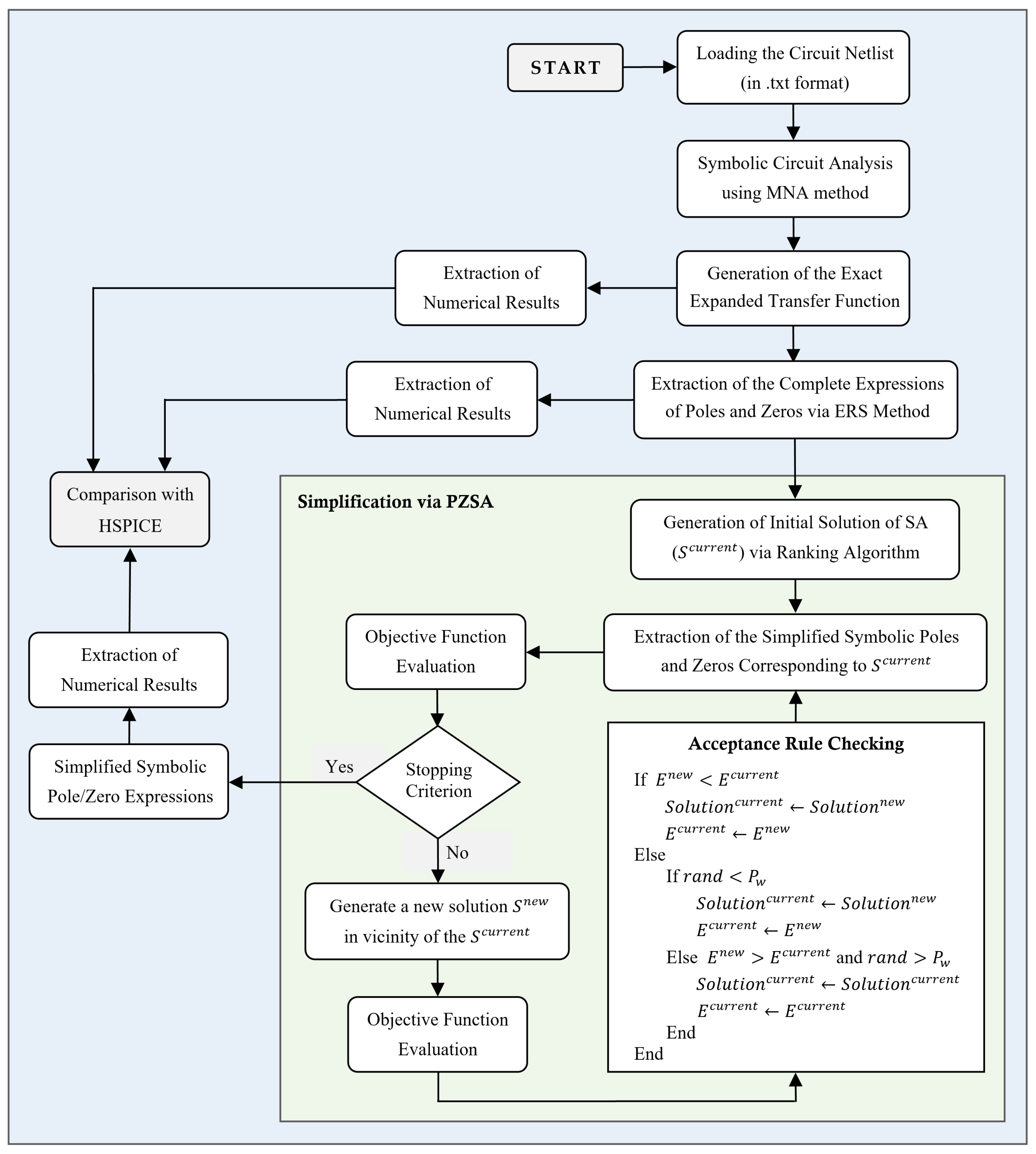
Figure 2.
Encoding of a solution: If =1, the -th symbolic term is present in the solution; otherwise, if =0, the -th term has been discarded from the solution.
Figure 2.
Encoding of a solution: If =1, the -th symbolic term is present in the solution; otherwise, if =0, the -th term has been discarded from the solution.
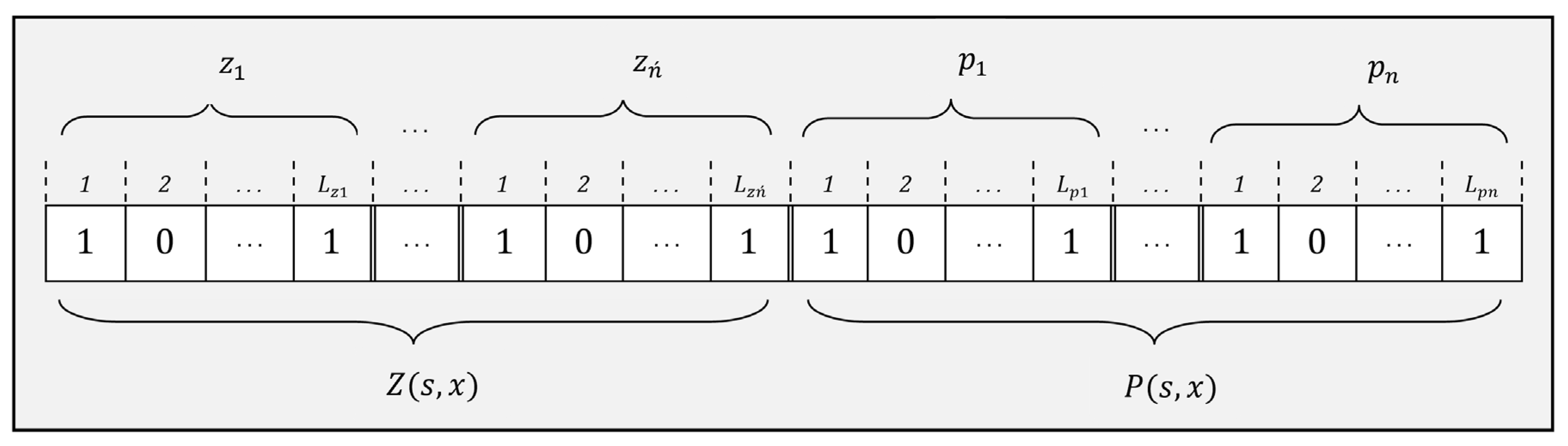
Figure 3.
Swap: a symbolic term is randomly selected and complemented.
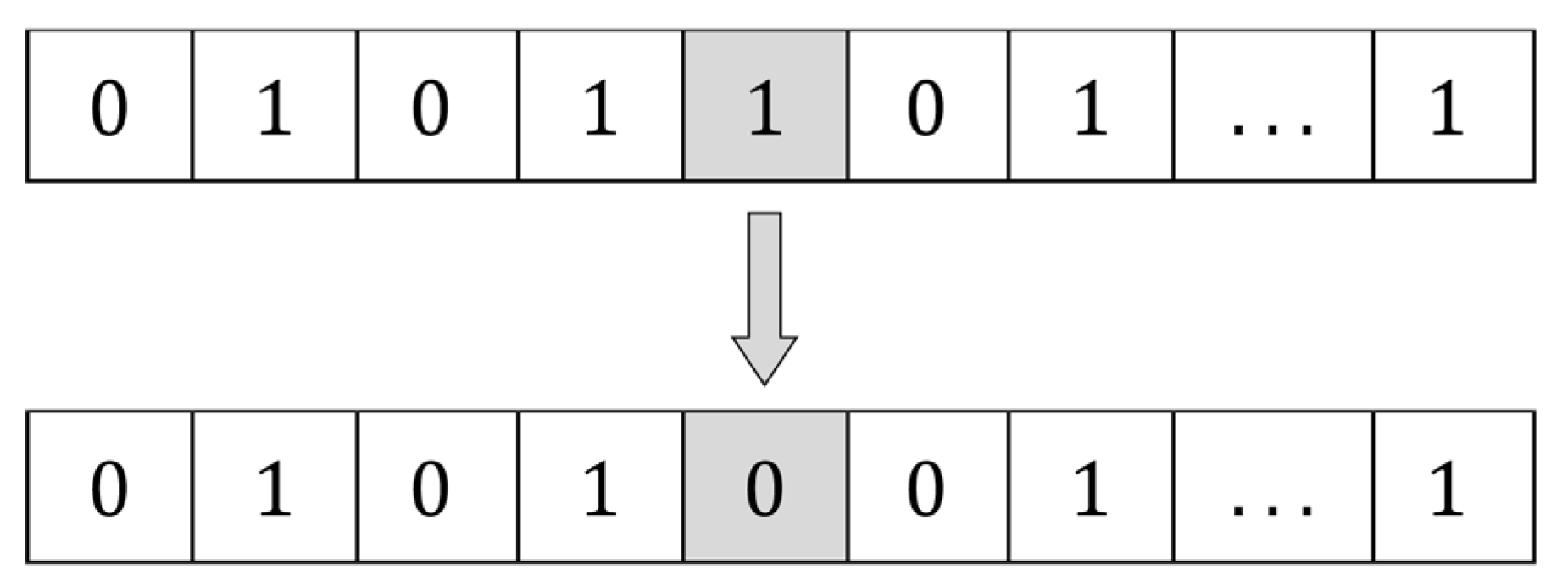
Figure 4.
Exchange: a term “0” and a term “1” are randomly selected and exchanged.
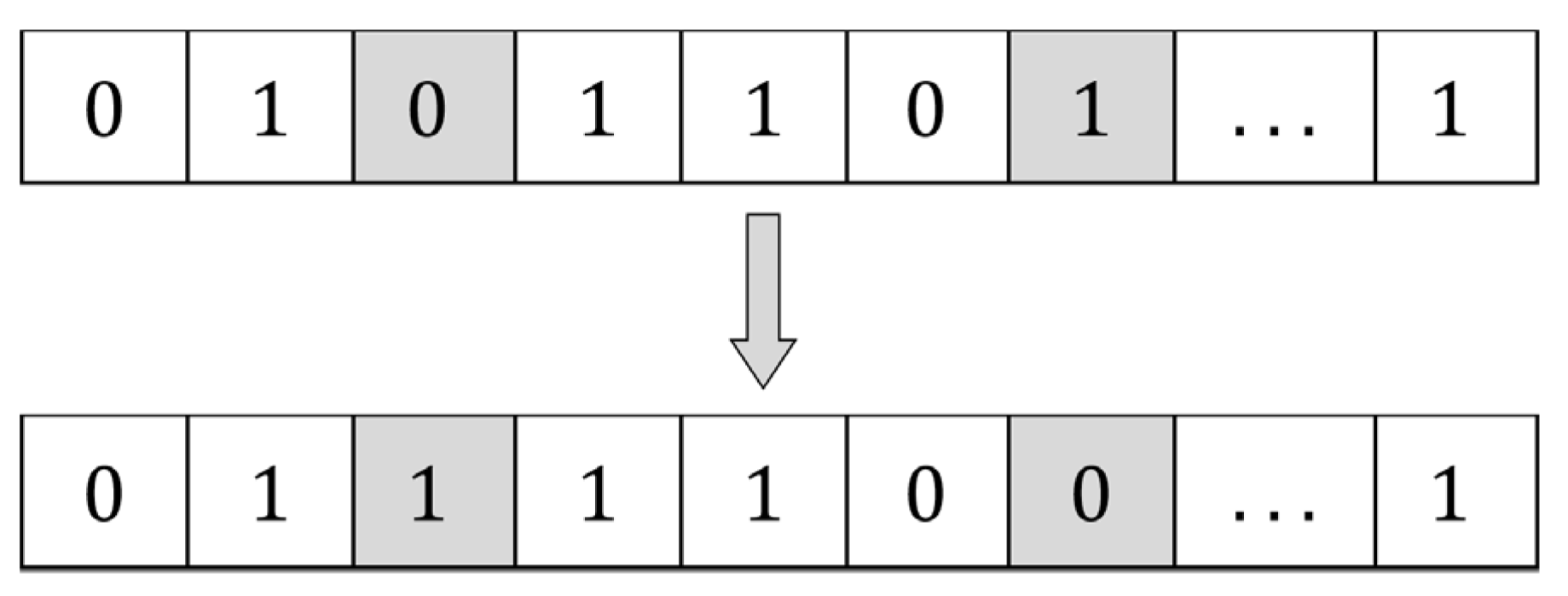
Figure 5.
Small signal representation of MOS transistors.
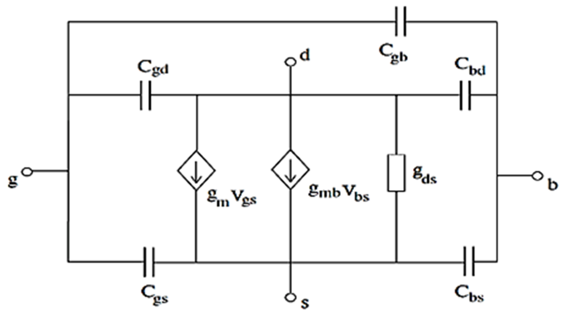
Figure 6.
Three-stage amplifier in the RCgm model.

Figure 7.
Two-stage compensation amplifier.
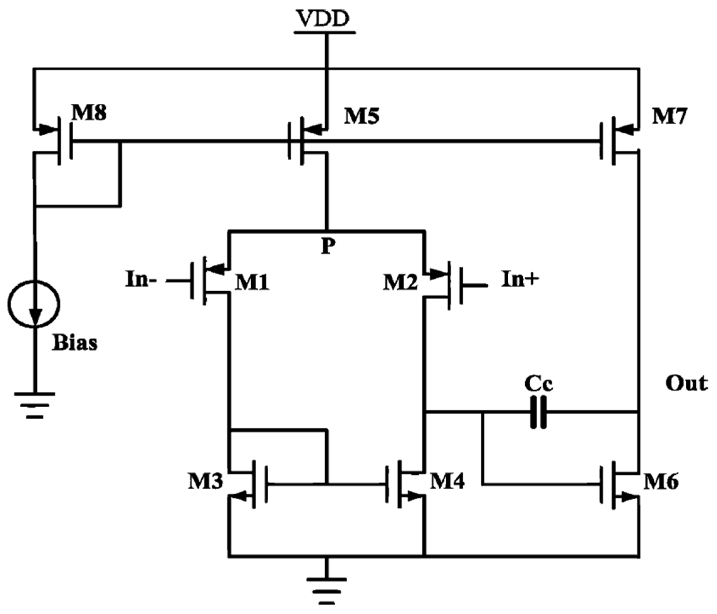
Figure 8.
Three-stage amplifier in the transistor model.
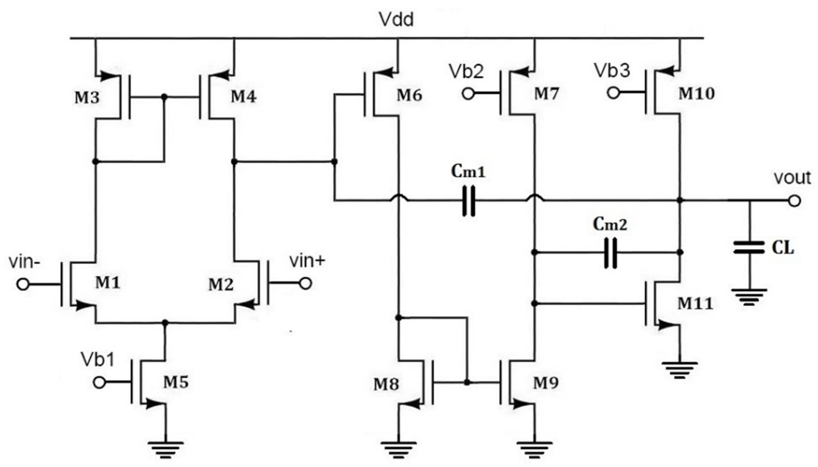

Table 1.
Notations.
| Sets / Parameters | Definition |
|---|---|
| Index of poles, | |
| Index of zeroes, | |
| Degree of the denominator within the exact expanded TF | |
| Degree of the numerator within the exact expanded TF | |
| Index of the symbolic terms, | |
| Number of symbolic terms within all pole/zero expressions | |
| Defined frequency bound range for the pole/zero extraction | |
| A binary decision parameter defining whether the -th symbolic term is used or not | |
| Set of poles in the frequency range of | |
| ZeroSet | Set of zeroes in the frequency range of |
| -th pole within the exact expanded TF | |
| -th extracted pole via ERS | |
| -th simplified pole via SA | |
| Mean pole displacements (in %) | |
| -th zero of the exact expanded TF | |
| -th extracted zero via ERS | |
| -th simplified zero via SA | |
| Mean zero displacements (in %) | |
| Maximum allowable pole/zero extraction error via ERS | |
| Maximum allowable pole/zero simplification error via SA |
Table 2.
Parameter settings.
| Phase | Parameter | Value/Description |
|---|---|---|
| Pole/Zero | in Eqs. (32,33) | 10 % |
| Extraction | 1 Hz | |
| Parameters | 10 × | |
| Maximum iterations | 5 × L | |
| SA | Local search mechanisms | Swap & Exchange |
| Parameters | in Eq. (41) | 10-5 |
| in Eq. (41) | 0 | |
| Objective | in Eq. (35) | 0.999 |
| Function | in Eq. (35) | 0.001 |
| Parameters | in Eqs. (38) and (39) | 20 % |
Table 3.
Number of terms within simplified symbolic poles/zeros in Circuit 1.
| Expression | Exact Symbolic | Ref. [34] | Ref. [13] | Ref. [15] | Proposed (Complete) | Proposed (Simplified) |
|---|---|---|---|---|---|---|
| P1 | N/A | N/A | 1 | 10 | 10 | 1 |
| P2 | N/A | N/A | 4 | 26 | 26 | 3 |
| P3 | N/A | N/A | 5 | 25 | 25 | 3 |
| Z1 | N/A | N/A | 2 | 9 | 3 | 2 |
| Z2 | N/A | N/A | 2 | 9 | 4 | 2 |
| Overall Transfer Function | 40 | 10 | N/A | N/A | N/A | N/A |
Table 4.
Numerical results for Circuit 1.
| Parameter | HSPICE | Exact Symbolic | Ref. [34] | Ref. [13] | Ref. [15] | Proposed (Complete) | Proposed (Simplified) |
|---|---|---|---|---|---|---|---|
| P1 (Hz) | -12.8 | -12.8 | -13.3 | -13.2 | -12.8 | -12.8 | -13.2 |
| P2 (MHz) | -3.19 | -3.19 | -3.49 | -3.19 | -2.96 | -2.96 | -3.18 |
| P3 (MHz) | -40.6 | -40.6 | -36.3 | -43.9 | -43.8 | -43.8 | -39.8 |
| Z1 (MHz) | 2.72 | 2.72 | 2.72 | 3.18 | 3.36 | 3.18 | 3.18 |
| Z2 (MHz) | -18.6 | -18.6 | -18.6 | -15.9 | -17.5 | -15.9 | -15.9 |
| Mean pole displacement (%) | N/A | N/A | 7.8 | 3.8 | 5 | 5 | 1.9 |
| Max pole displacement (%) | N/A | N/A | 10.6 | 8.36 | 7.9 | 7.9 | 3.5 |
| Mean zero displacement (%) | N/A | N/A | 0.03 | 15.9 | 14.7 | 15.8 | 15.9 |
| Max zero displacement (%) | N/A | N/A | 0.04 | 17.1 | 23.6 | 17.1 | 17.1 |
Table 5.
Number of terms within the simplified symbolic poles/zeroes in Circuit 2.
| Expression | Exact Symbolic | Ref. [34] | Ref. [13] | Ref. [15] | Proposed (Complete) | Proposed (Simplified) |
|---|---|---|---|---|---|---|
| P1 | N/A | N/A | 5 | 104 | 104 | 5 |
| P2 | N/A | N/A | 7 | 82 | 82 | 2 |
| Z | N/A | N/A | 4 | 18 | 18 | 2 |
| Overall Transfer Function | 134 | 11 | N/A | N/A | N/A | N/A |
Table 6.
Numerical results for Circuit 2.
| Parameter | HSPICE | Exact Symbolic | Ref. [34] | Ref. [13] | Ref. [15] | Proposed (Complete) | Proposed (Simplified) |
|---|---|---|---|---|---|---|---|
| P1 (KHz) | -177.1 | -178.5 | -192 | -152.8 | -178.4 | -178.4 | -152.8 |
| P2 (MHz) | -377.4 | -435.4 | -409.1 | -341 | -435.6 | -435.6 | -409.3 |
| Z (MHz) | 407.2 | 409.3 | 409.3 | 409.3 | 409.3 | 409.3 | 409.3 |
| Mean pole displacement (%) | N/A | N/A | 6.8 | 18 | 0.04 | 0.04 | 10.2 |
| Max pole displacement (%) | N/A | N/A | 7.5 | 21.7 | 0.04 | 0.04 | 14.4 |
| Zero displacement (%) | N/A | N/A | 0.01 | 0.01 | 0 | 0 | 0.01 |
Table 7.
Number of terms within the simplified symbolic poles/zeroes in Circuit 3.
| Expression | Exact Symbolic | Ref. [34] | Ref. [13] | Ref. [15] | Proposed (Complete) | Proposed (Simplified) |
|---|---|---|---|---|---|---|
| P1 | N/A | N/A | 29 | 714 | 714 | 9 |
| P2 | N/A | N/A | 21 | 837 | 837 | 3 |
| P3 | N/A | N/A | 23 | 330 | 330 | 3 |
| Z1 | N/A | N/A | 15 | 75 | 75 | 2 |
| Z2 | N/A | N/A | 13 | 105 | 105 | 2 |
| Overall Transfer Function | 1320 | 18 | N/A | N/A | N/A | N/A |
Table 8.
Numerical results for Circuit 3.
| Parameter | HSPICE | Exact Symbolic | Ref. [34] | Ref. [13] | Ref. [15] | Proposed (Complete) | Proposed (Simplified) |
|---|---|---|---|---|---|---|---|
| P1 (Hz) | -27.7 | -27.9 | -20.6 | -20.5 | -27.9 | -27.9 | -22.8 |
| P2 (MHz) | -1.84 | -1.84 | -2.03 | -2.16 | -1.76 | -1.76 | -2.07 |
| P3 (MHz) | -36.6 | -40.2 | -36.3 | -36.1 | -42.1 | -42.1 | -35.7 |
| Z1 (MHz) | 1.4 | 1.4 | 1.4 | 2.23 | 1.62 | 1.62 | 1.62 |
| Z2 (MHz) | -10.3 | -10.2 | -10.5 | -7.37 | -8.81 | -8.81 | -9.1 |
| Mean pole displacement (%) | N/A | N/A | 15.6 | 18 | 3 | 3 | 14.2 |
| Max pole displacement (%) | N/A | N/A | 26.4 | 26.5 | 4.6 | 4.6 | 18.4 |
| Mean zero displacement (%) | N/A | N/A | 1.7 | 43.5 | 14.8 | 14.8 | 13.5 |
| Max zero displacement (%) | N/A | N/A | 2.9 | 59.3 | 15.9 | 15.9 | 16.1 |
Disclaimer/Publisher’s Note: The statements, opinions and data contained in all publications are solely those of the individual author(s) and contributor(s) and not of MDPI and/or the editor(s). MDPI and/or the editor(s) disclaim responsibility for any injury to people or property resulting from any ideas, methods, instructions or products referred to in the content. |
© 2023 by the authors. Licensee MDPI, Basel, Switzerland. This article is an open access article distributed under the terms and conditions of the Creative Commons Attribution (CC BY) license (http://creativecommons.org/licenses/by/4.0/).
Copyright: This open access article is published under a Creative Commons CC BY 4.0 license, which permit the free download, distribution, and reuse, provided that the author and preprint are cited in any reuse.


