
Submitted:
24 September 2026
Posted:
29 September 2026
You are already at the latest version
Abstract
Concentration polarization at the surface of ion-exchange membranes limits the rate of mass transfer and determines the energy consumption of electrodialysis. Turbulence-promoting spacers and profiling of the membrane surface are the two traditional remedies; however, they are almost always considered separately, and non-conducting spacers shade the membrane and increase the channel resistance. In this work, a two-dimensional mathematical model of ion transport in a flow-through desalination channel is developed on the basis of the coupled Nernst–Planck–Poisson and Navier–Stokes equations in the potentiodynamic mode. Using the Poisson equation instead of the local electroneutrality assumption makes it possible to account for the space-charge region and describe electroconvection "from first principles." Eight channel configurations were compared: a smooth or structured cation-exchange membrane, with or without profiled spacers placed in various positions. It is shown that the structured surface and profiled spacers act synergistically: the spacers direct the solution from the flow core toward the membrane's developed surface relief, and the overall benefit exceeds the sum of the individual effects. The combined design raises the limiting current by a factor of about 1.4, shortens the limiting-current plateau, increases the current at 1.4 V by 40–45%, provides a 35% increase of the active membrane area, a 40% reduction of concentration polarization, a 28% acceleration of desalination, a ×1.5 increase of the ion flux, and a 15% reduction of the working voltage. The main conclusion agrees with an independent 3D multiphysics study supported by experiments with physically manufactured profiled membranes.
Keywords:
electrodialysis
; electromembrane systems
; concentration polarization
; electroconvection
; Nernst–Planck–Poisson equations
; Navier–Stokes equations
; spacers
; profiled membranes
; limiting current
; finite element method
MSC: 35Q35; 35Q30; 65M60; 76W05; 78A57
1. Introduction
Electrodialysis (ED) is one of the most mature and energy-efficient membrane technologies for the desalination of brackish water, the treatment of industrial effluents, and the recovery of valuable components from multicomponent solutions [1,2,3]. The performance of any ED apparatus is ultimately limited by concentration polarization: the depletion of the electrolyte in a thin diffusion layer adjacent to the ion-exchange membrane, which reduces the local conductivity, gives rise to the limiting current density, and sharply increases the energy consumption of the process [4,5]. Two engineering strategies have traditionally been used to mitigate this limitation. The first is the insertion of turbulence-promoting spacers into the desalination channels, which mix the solution and renew the near-membrane layer; the second is the modification of the membrane itself—profiling or structuring of its surface, which increases the active area and disturbs the depleted layer [6,7,8]. Both strategies, however, have well-known drawbacks: non-conducting net spacers shade a considerable part of the membrane surface and increase both the electrical and the hydraulic resistance of the channel [6,9], while surface profiling alone provides only a moderate gain if the hydrodynamics of the channel is not adapted to the new relief [7,10]. The central question addressed in the present work is whether these two factors, acting together, can produce a synergistic—rather than merely additive—enhancement of mass transfer, and how such a combined design should be described mathematically.
The state of the art in the mathematical description of ion transfer in electromembrane systems has been shaped over the last two decades by models based on the coupled Nernst–Planck–Poisson (NPP) equations, in many cases supplemented by the Navier–Stokes equations for the fluid flow. The classical results of Rubinstein and co-workers on the instability of concentration polarization and electroosmotic slip of the second kind [11,12,13] demonstrated that the space charge region forming at the depleted membrane interface generates electroconvective vortices that destroy the diffusion layer and enable overlimiting current transfer; the electrokinetic origin of this phenomenon goes back to the theory of electrokinetic phenomena of the second kind developed by Dukhin and Mishchuk [14,15]. Direct numerical simulations [16,17,18,19] and experiments [20] subsequently mapped the transition from stable vortex patterns to chaotic electroconvection, and comprehensive reviews [5,21,22,23] systematized the mechanisms of overlimiting transfer in ED. Within the scientific school to which the authors belong, basic two-dimensional NPP–Navier–Stokes models of overlimiting mass transfer enhanced by electroconvection were constructed [24,25], two-dimensional galvanodynamic and potentiodynamic formulations were developed [26,27], the nature of transition times on chronopotentiograms of heterogeneous membranes was established [28,29], and the space-charge breakdown phenomenon with its characteristic spatio-temporal concentration patterns was discovered [30]. These works showed that NPP-based models, which retain the Poisson equation instead of the local electroneutrality assumption, correctly reproduce the fine structure of the near-membrane region—precisely the region where spacers and surface modification act.
A parallel and largely independent line of research concerns the hydrodynamic optimization of the desalination channel itself. Computational fluid dynamics (CFD) studies of spacer-filled channels [9,31,32] quantified the trade-off between mixing intensification and pressure losses and identified the shading (blockage) of the membrane surface by spacer filaments as the principal drawback of conventional net spacers; modern reviews of feed spacers, including additively manufactured (3D-printed) ones, emphasize that new degrees of freedom in spacer geometry open the possibility of task-specific channel designs [33]. On the other hand, it has been shown that profiled (structured) ion-exchange membranes—produced via a hot-forming process—reduce channel resistance and improve electrochemical characteristics in both conventional and reverse electrodialysis [7,34,35]; the physicochemical properties of such profiled heterogeneous membranes were characterized in detail in [8], and the influence of surface charge and hydrophobicity on electroconvection was demonstrated in [36]. Nevertheless, in the overwhelming majority of published models the spacer and the membrane relief are considered separately: CFD spacer models usually ignore the space charge and electroconvection, while NPP models of profiled membranes are formulated for spacer-free channels. To the best of our knowledge, the combined action of a structured membrane surface and specially profiled near-membrane spacers—within a unified model and accounting for the influence of space charge—has not been systematically investigated.
Finally, the most recent development directly motivating this study is the transition to fully three-dimensional multiphysics simulations of ED channels. In the study [37], an ED channel with profiled membranes was compared with a spacer-filled channel on the basis of a coupled multiphysics model, and it was shown experimentally and numerically that directing fresh, concentrated solution onto the membrane surface—there by the normal velocity component around conical protrusions—is the key driver of the limiting-current increase, the strongest effect always being achieved by a combination of factors. Our earlier work [38] laid the foundation for the 3D extension of the present model. The present paper occupies an intermediate, methodologically important position: using a two-dimensional NPP-Navier-Stokes model in the potentiodynamic regime, we systematically compare eight channel configurations—smooth and structured membranes, with and without profiled spacers in several locations—and, for the first time, within the framework of a single model, taking into account the space charge, we quantitatively characterize the synergistic effect of spacers and membrane surface modification. The profiled shape of the spacers was chosen because, at a small angle of attack, it creates minimal hydraulic losses, while directing the solution from the flow core to the membrane and thinning the diffusion layer.
The rest of the paper is organized as follows. Section 2 formulates the mathematical model: the geometry of the desalination channel, the governing NPP–Navier–Stokes equations, and the boundary conditions of the potentiodynamic mode. Section 3 describes the numerical method. Section 4 presents and discusses the results: flow and concentration fields for all eight configurations, current–voltage characteristics, and a comparison with results [37]. Section 5 summarizes the conclusions and formulates practical recommendations for the design of next-generation ED channels.
2. Mathematical Model
2.1. Geometry of the Desalination Channel
We consider the half of a flow-through ED desalination channel of width H = 2 mm and length L = 8 mm, bounded on the right by a cation-exchange membrane (CEM); the local electroneutrality condition is imposed on the left boundary representing the middle of the channel (Figure 1). A binary electrolyte (NaCl) solution is fed from below; at the inlet, one half of the developed parabolic Poiseuille velocity profile is prescribed. The potential difference is applied between the channel boundaries, so that the cations migrate toward the CEM on the right.
Eight configurations of the channel are compared (Figure 2 and Figure 3). In configuration (a) the CEM surface is smooth. In configuration (b) the surface is structured: semicircular protrusions of radius 0.5 mm with a period of 1 mm are placed on the membrane, increasing its active area; various protrusion shapes and arrangements were examined in our previous works and in the recent fundamental 3D study [37]. In configuration (c), wing-shaped (airfoil) spacers with a chord of 0.68 mm and an angle of attack of 30° are added directly at the structured surface, each wing being located upstream of a protrusion. In configuration (d) the same wings are shifted deeper into the solution bulk and upstream. Configurations (e)–(h) (Figure 3) continue this series by varying the wing positions relative to the protrusions and the distance from the membrane, which makes it possible to identify how the geometry tunes the near-membrane hydrodynamics.
2.2. Governing Equations
The transport of the ions of a binary electrolyte is described by the Nernst–Planck equations for the fluxes, the material balance equations, the Poisson equation for the electric potential, and the expression for the current density:
ε0εrΔφ = −F (z1C1 + z2C2),
It is essential that Equation (3) is the Poisson equation and not the local electroneutrality condition z1C1 + z2C2 = 0. Retaining the Poisson equation allows the model to resolve the extended space charge region that forms at the depleted membrane surface at overlimiting currents and, therefore, to describe electroconvection—the very mixing mechanism that is either ignored or introduced phenomenologically in most CFD spacer models [11,12,13,21].
The fluid flow is described by the Navier–Stokes equations for an incompressible liquid with the electric volume force:
where P is the pressure, ρ0 and ν are the density and kinematic viscosity of the solution, and is the Coulomb body force acting on the space charge. Through this force, Equations (1)–(6) form a fully coupled electrohydrodynamic system: the space charge computed from (3) drives the flow via (5), and the flow, in turn, convects the ions via (1).
2.3. Boundary and Initial Conditions
At the inlet (y = 0), one half of the Poiseuille profile with the mean velocity V0 and the feed concentration C0 is prescribed. At the outlet (y = L), the standard soft (outflow) conditions are imposed. On the left boundary (x = 0, middle of the channel), the local electroneutrality condition and zero normal fluxes of momentum are used. On the CEM surface (including the surfaces of the protrusions), the counterion concentration is fixed and equal to the exchange capacity–controlled interface value, the coion flux is zero (an ideally selective membrane), and the no-slip condition holds for the velocity; the surfaces of the wing spacers are impermeable non-conducting walls with the no-slip and zero-normal-flux conditions. The process is simulated in the potentiodynamic mode: the potential difference grows linearly in time, Δφ(t) = αt, with the sweep rate α = 5 mV/s, so that t = 280 s corresponds to Δφ = 1.4 V. The initial conditions correspond to the uniform feed concentration and the developed Poiseuille flow at zero potential difference.
3. Numerical Method
The coupled initial–boundary value problem (1)–(6) is solved by the finite element method implemented in the COMSOL Multiphysics package [41]. Taylor–Hood elements (quadratic for the velocity, linear for the pressure) are used for the hydrodynamic subproblem, and quadratic Lagrange elements for the concentrations and the potential. The mesh is strongly refined toward the membrane surface so that the smallest elements resolve both the quasi-equilibrium electric double layer and the extended space charge region; boundary-layer meshing is also applied around the wing spacers and the protrusions. Time integration is performed by an implicit backward differentiation formula (BDF) scheme of variable order with adaptive time stepping; the nonlinear systems at each step are solved by the Newton method with a direct sparse solver for the linearized systems. The main computational parameters are: mean flow velocity V0 = 1 mm/s; feed concentration C0 from 0.01 to 10 mol/m³; Péclet number Pe = 976; Reynolds number Re = 8, i.e., the flow is laminar but, in the structured configurations, essentially vortical. Mesh-refinement tests showed that a further twofold refinement changes the computed current density by less than 1%, which was accepted as the convergence criterion.
4. Results and Discussion
4.1. Flow and Concentration Fields
Figure 4 shows the streamlines (white) and the cation concentration fields at t = 280 s (Δφ = 1.4 V) for configurations (a)–(d); Figure 5 shows the same fields for configurations (e)–(h). Red corresponds to the feed concentration (C≈10−2 mol/m³ in the color-bar units), blue to the depleted zone at the membrane.
In the smooth channel (a), the flow is strictly parallel and the depleted (blue) layer grows monotonically along the membrane, reaching its maximum thickness at the outlet; small electroconvective vortices are visible only inside the thin blue strip. Structuring of the surface (b) already changes the picture qualitatively: the protrusions periodically interrupt the growth of the diffusion layer, and vortex zones develop in the hollows between them, where the depleted solution is trapped and locally mixed. The addition of wing spacers at the membrane (c) deflects the streamlines of the concentrated core toward the protrusion tops; the red core approaches the membrane much more closely, and the blue layer is compressed to a thin film on the protrusion crests. Finally, when the wings are shifted into the bulk and upstream (d), each wing works as a guide vane: it directs a jet of fresh, concentrated solution exactly into the gap between two protrusions, so that the depleted zone survives only in narrow shadow regions behind the protrusions. Configurations (e)–(h) (Figure 5) demonstrate the sensitivity of this mechanism to the wing position: moving the wings too far from the membrane (e,f) weakens the jet effect, whereas the optimized positions (g,h) reproduce, and slightly exceed, the effect of configuration (d) while distributing the mixing more uniformly along the channel. In all structured configurations the streamline pattern remains stationary and laminar (Re = 8); the intensification is thus achieved not by turbulence but by the deterministic redirection of the laminar flow, complemented by electroconvective micro-vortices at the depleted interface.
4.2. Current–Voltage Characteristics
Figure 6 presents the current–voltage characteristics (CVCs) of all eight configurations computed in the potentiodynamic mode. Each curve exhibits the three classical regimes: the initial ohmic rise, the limiting-current plateau, and the secondary growth in the overlimiting region driven by electroconvection [11,12,13,21].
Three quantitative conclusions follow from Figure 6. First, at any given voltage the channels combining the structured membrane with wing spacers—configurations (d), (g), and (h)—conduct the largest current: at Δφ = 1.4 V their current density reaches 2.8–2.9 A/m², versus about 2.0 A/m² for the smooth channel (a), i.e., a gain of roughly 40–45%. Second, the limiting-current plateau of the combined configurations is both higher (≈1.5 A/m² versus ≈1.05 A/m² for the smooth channel, a ×1.4 increase of the limiting current itself) and visibly shorter: the transition to the overlimiting regime occurs at Δφ≈0.8 V instead of ≈1.0 V. Third, the oscillations of the current in the overlimiting branch, which reflect the unsteady dynamics of electroconvective vortices, start earlier and are more regular near the modified surface—the protrusions act as fixed nucleation sites for the vortices, which stabilizes the overlimiting transfer, in line with the scaling laws established for electroconvective vortices in [42]. It is important that the purely additive estimate fails here: the gain of the combined configuration (d) over the smooth channel exceeds the sum of the separate gains of the structured surface (b) and of wing spacers placed at a smooth membrane, which is precisely the synergistic effect announced in the title. The physical reason is that the protrusions are efficient only when fresh solution is delivered to them, and the wings are efficient only when the surface they feed has an increased active area and vortex-anchoring relief.
4.3. Comparison with the Independent 3D Study and Experiment
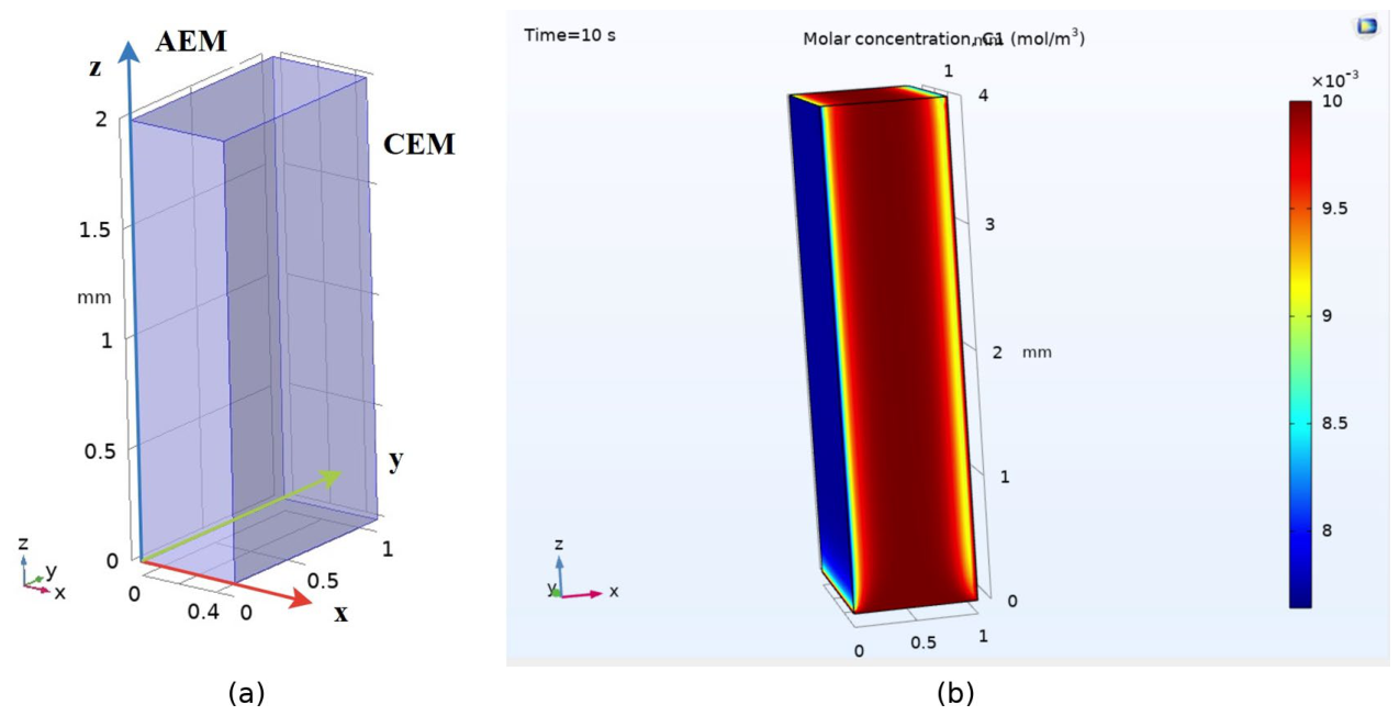
A natural question is to what extent the present two-dimensional results can be trusted. We compared them with the independent three-dimensional multiphysics study [37], in which an ED channel with profiled membranes (conical protrusions of height ≈200 µm arranged with a ≈1.3 mm pitch, geometries physically manufactured and imaged by electron microscopy) was compared with a spacer-filled channel, both numerically and experimentally. The main physical conclusion coincides with ours: intensifying the near-surface mixing thins the diffusion layer and raises the limiting current, and the key driver is the delivery of fresh concentrated solution onto the membrane—in our model this role is played by the wing spacers, in the 3D study by the normal velocity component arising around the conical protrusions. In both works the strongest effect is achieved by a combination of factors rather than by any single one, and the predicted relative gains of the limiting and overlimiting currents are of the same order (tens of percent). The agreement of two models of different dimensionality, formulated by partially independent teams and supported in [37] by direct experiments with physically manufactured profiled membranes, gives confidence in the reliability of the conclusions. The logical continuation of the present work is its own extension to three dimensions; the first step—a 3D geometry of the cell formed by an anion-exchange and a cation-exchange membrane and the computation of the evolving 3D concentration field—has been made in [38] and is illustrated in Figure 7.
The three-dimensional formulation makes it possible to take into account the real membrane relief and the spatial shape of the spacers, and not only their cross-sections; the depleted zone in Figure 7b is seen to form at the CEM and to develop along the channel, in full qualitative agreement with the two-dimensional fields of Figure 4 and Figure 5.
4.4. Integral Effect of the Synergistic Design
Summarizing the parametric computations over all configurations, the proposed synergistic design—the structured membrane surface combined with optimally placed wing spacers—delivers, relative to the smooth spacer-free channel: an increase of the active membrane area by 35%; a reduction of the concentration polarization (measured by the deficit of the near-membrane concentration) by 40%; an acceleration of desalination by 28%; a ×1.5 increase of the ion flux through the membrane; and a 15% reduction of the working voltage required for a given current. Thus the design wins simultaneously in productivity and in energy efficiency—exactly the combination required for practical electrodialysis.
5. Conclusions
A two-dimensional mathematical model of ion transport in an ED desalination channel has been developed on the basis of the coupled Nernst–Planck–Poisson and Navier–Stokes equations in the potentiodynamic mode. Because the model retains the Poisson equation instead of the local electroneutrality assumption, it resolves the space charge region and describes electroconvection from first principles, which allowed a correct comparison of eight channel configurations combining a smooth or structured cation-exchange membrane with wing-shaped near-membrane spacers in different arrangements.
The main results are as follows. (1) The combination of a structured membrane surface and wing spacers acts synergistically: the wings steer the concentrated core flow onto the enlarged, vortex-anchoring membrane relief, so that the total gain exceeds the sum of the separate effects. (2) The combined configurations increase the limiting current by a factor of about 1.4, shorten the limiting-current plateau, shift the onset of the overlimiting regime from ≈1.0 to ≈0.8 V, and raise the current at 1.4 V by 40–45% relative to the smooth channel. (3) Integrally, the synergistic design provides a 35% increase of the active membrane area, a 40% reduction of concentration polarization, a 28% acceleration of desalination, a ×1.5 increase of the ion flux, and a 15% reduction of the working voltage. (4) The main physical conclusion—that the delivery of fresh concentrated solution onto the membrane by a combination of geometric factors is the key driver of the limiting-current increase—coincides with the conclusion of the independent 3D multiphysics study [37] supported by experiments with physically manufactured profiled membranes, which validates the model.
Practical recommendations follow directly from the computations: the optimal relief consists of protrusions of about 200 µm height with a pitch of about 500 µm—the balance point between the area gain and the hydraulic resistance; wing spacers with a chord of ≈0.7 mm and an angle of attack of ≈30° should be placed upstream of the protrusions at a small distance from the surface. Additive manufacturing (3D printing) of membranes and spacers with the prescribed relief [33] and optimization of the geometry assisted by machine learning and graph-based data analysis [43] are the natural technological routes for implementing such designs. The next steps of the model development are the systematic 3D extension started in [37,38] and the inclusion of water dissociation and other overlimiting effects that remain outside the present formulation; the recently reviewed one-dimensional current-controlled approaches [44] provide a convenient starting point for such extensions.
Author Contributions
Conceptualization, A.V.O., A.K. and M.U.; methodology, A.V.O., E.K. and M.U.; software, A.L. and A.Y.O.; validation, A.K.; formal analysis, A.V.O., E.K.; investigation, A.K.; E.K.; writing—original draft preparation, A.K., E.K.; writing—review and editing, resources, A.K.; A.V.O.; visualization, A.L. and A.Y.O.; supervision, A.K.; project administration, A.K.; funding acquisition, A.K. All authors have read and agreed to the published version of the manuscript.
Funding
This research was funded by the Russian Science Foundation, research project No. 24-19-00648, https://rscf.ru/project/24-19-00648/.
Data Availability Statement
The original contributions presented in this study are included in the article. Further inquiries can be directed to the corresponding author.
Conflicts of Interest
The authors declare no conflicts of interest.
Abbreviations
The following abbreviations are used in this manuscript:
| ED | Electrodialysis |
| CEM/AEM | Cation-/anion-exchange membrane |
| NPP | Nernst–Planck–Poisson (system of equations) |
| CVC | Current–voltage characteristic |
References
- Strathmann, H. Electrodialysis, a mature technology with a multitude of new applications. Desalination 2010, 264, 268–288. [CrossRef]
- Campione, A.; Gurreri, L.; Ciofalo, M.; Micale, G.; Tamburini, A.; Cipollina, A. Electrodialysis for water desalination: A critical assessment of recent developments on process fundamentals, models and applications. Desalination 2018, 434, 121–160. [CrossRef]
- Al-Amshawee, S.; Yunus, M.Y.B.M.; Azoddein, A.A.M.; Hassell, D.G.; Dakhil, I.H.; Hasan, H.A. Electrodialysis desalination for water and wastewater: A review. Chem. Eng. J. 2020, 380, 122231. [CrossRef]
- Krol, J.J.; Wessling, M.; Strathmann, H. Concentration polarization with monopolar ion exchange membranes: Current–voltage curves and water dissociation. J. Membr. Sci. 1999, 162, 145–154. [CrossRef]
- Nikonenko, V.V.; Pismenskaya, N.D.; Belova, E.I.; Sistat, P.; Huguet, P.; Pourcelly, G.; Larchet, C. Intensive current transfer in membrane systems: Modelling, mechanisms and application in electrodialysis. Adv. Colloid Interface Sci. 2010, 160, 101–123. [CrossRef]
- Balster, J.; Stamatialis, D.F.; Wessling, M. Membrane with integrated spacer. J. Membr. Sci. 2006, 282, 351–361.
- Vermaas, D.A.; Saakes, M.; Nijmeijer, K. Power generation using profiled membranes in reverse electrodialysis. J. Membr. Sci. 2011, 385–386, 234–242. [CrossRef]
- Zabolotskii, V.I.; Loza, S.A.; Sharafan, M.V. Physicochemical properties of profiled heterogeneous ion-exchange membranes. Russ. J. Electrochem. 2005, 41, 1053–1060.
- Gurreri, L.; Tamburini, A.; Cipollina, A.; Micale, G.; Ciofalo, M. CFD prediction of concentration polarization phenomena in spacer-filled channels for reverse electrodialysis. J. Membr. Sci. 2014, 468, 133–148. [CrossRef]
- Pawlowski, S.; Crespo, J.G.; Velizarov, S. Profiled ion exchange membranes: A comprehensible review. Int. J. Mol. Sci. 2019, 20, 165. [CrossRef]
- Rubinstein, I.; Shtilman, L. Voltage against current curves of cation exchange membranes. J. Chem. Soc. Faraday Trans. II 1979, 75, 231–246. [CrossRef]
- Rubinstein, I.; Zaltzman, B. Electro-osmotic slip of the second kind and instability in concentration polarization at electrodialysis membranes. Phys. Rev. E 2000, 62, 2238–2251. [CrossRef]
- Zaltzman, B.; Rubinstein, I. Electro-osmotic slip and electroconvective instability. J. Fluid Mech. 2007, 579, 173–226. [CrossRef]
- Dukhin, S.S. Electrokinetic phenomena of the second kind and their applications. Adv. Colloid Interface Sci. 1991, 35, 173–196. [CrossRef]
- Mishchuk, N.A. Concentration polarization of interface and non-linear electrokinetic phenomena. Adv. Colloid Interface Sci. 2010, 160, 16–39. [CrossRef]
- Pham, V.S.; Li, Z.; Lim, K.M.; White, J.K.; Han, J. Direct numerical simulation of electroconvective instability and hysteretic current–voltage response of a permselective membrane. Phys. Rev. E 2012, 86, 046310. [CrossRef]
- Demekhin, E.A.; Nikitin, N.V.; Shelistov, V.S. Direct numerical simulation of electrokinetic instability and transition to chaotic motion. Phys. Fluids 2013, 25, 122001. [CrossRef]
- Druzgalski, C.L.; Andersen, M.B.; Mani, A. Direct numerical simulation of electroconvective instability and hydrodynamic chaos near an ion-selective surface. Phys. Fluids 2013, 25, 110804. [CrossRef]
- Davidson, S.M.; Wessling, M.; Mani, A. On the dynamical regimes of pattern-accelerated electroconvection. Sci. Rep. 2016, 6, 22505. [CrossRef]
- de Valença, J.C.; Wagterveld, R.M.; Lammertink, R.G.H.; Tsai, P.A. Dynamics of microvortices induced by ion concentration polarization. Phys. Rev. E 2015, 92, 031003(R). [CrossRef]
- Nikonenko, V.V.; Mareev, S.A.; Pismenskaya, N.D.; Uzdenova, A.M.; Kovalenko, A.V.; Urtenov, M.Kh.; Pourcelly, G. Effect of electroconvection and its use in intensifying the mass transfer in electrodialysis (Review). Russ. J. Electrochem. 2017, 53, 1122–1144. [CrossRef]
- Mani, A.; Wang, K.M. Electroconvection near electrochemical interfaces: Experiments, modeling, and computation. Annu. Rev. Fluid Mech. 2020, 52, 509–529. [CrossRef]
- Rubinstein, I.; Zaltzman, B. Equilibrium electroconvective instability. Phys. Rev. Lett. 2015, 114, 114502. [CrossRef]
- Urtenov, M.K.; Uzdenova, A.M.; Kovalenko, A.V.; Nikonenko, V.V.; Pismenskaya, N.D.; Vasil’eva, V.I.; Sistat, P.; Pourcelly, G. Basic mathematical model of overlimiting transfer enhanced by electroconvection in flow-through electrodialysis membrane cells. J. Membr. Sci. 2013, 447, 190–202. [CrossRef]
- Uzdenova, A.M.; Kovalenko, A.V.; Urtenov, M.K.; Nikonenko, V.V. Competition between diffusion and electroconvection at an ion-selective surface in intensive current regimes. Adv. Colloid Interface Sci. 2016, 235, 233–246. [CrossRef]
- Uzdenova, A. 2D mathematical modelling of overlimiting transfer enhanced by electroconvection in flow-through electrodialysis membrane cells in galvanodynamic mode. Membranes 2019, 9, 39. [CrossRef]
- Uzdenova, A.; Urtenov, M. Potentiodynamic and galvanodynamic regimes of mass transfer in flow-through electrodialysis membrane systems: Numerical simulation of electroconvection and current–voltage curve. Membranes 2020, 10, 49. [CrossRef]
- Mareev, S.A.; Butylskii, D.Yu.; Pismenskaya, N.D.; Nikonenko, V.V. Chronopotentiometry of ion-exchange membranes in the overlimiting current range. Transition time for a finite-length diffusion layer: Modeling and experiment. J. Membr. Sci. 2016, 500, 171–179. [CrossRef]
- Mareev, S.A.; Nebavskiy, A.V.; Nichka, V.S.; Urtenov, M.K.; Nikonenko, V.V. The nature of two transition times on chronopotentiograms of heterogeneous ion exchange membranes: 2D modelling. J. Membr. Sci. 2019, 575, 179–190. [CrossRef]
- Kovalenko, A.V.; Wessling, M.; Nikonenko, V.V.; Mareev, S.A.; Moroz, I.A.; Evdochenko, E.; Urtenov, M.K. Space-charge breakdown phenomenon and spatio-temporal ion concentration and fluid flow patterns in overlimiting current electrodialysis. J. Membr. Sci. 2021, 636, 119583. [CrossRef]
- Koutsou, C.P.; Yiantsios, S.G.; Karabelas, A.J. Direct numerical simulation of flow in spacer-filled channels: Effect of spacer geometrical characteristics. J. Membr. Sci. 2007, 291, 53–69. [CrossRef]
- Gurreri, L.; Tamburini, A.; Cipollina, A.; Micale, G. Electrodialysis applications in wastewater treatment for environmental protection and resources recovery: A systematic review on progress and perspectives. Membranes 2020, 10, 146. [CrossRef]
- Qian, X.; Anvari, A.; Hoek, E.M.V.; McCutcheon, J.R. Advancements in conventional and 3D printed feed spacers in membrane modules. Desalination 2023, 556, 116518. [CrossRef]
- Loza, S.; Loza, N.; Kutenko, N.; Smyshlyaev, N. Profiled ion-exchange membranes for reverse and conventional electrodialysis. Membranes 2022, 12, 985. [CrossRef]
- Larchet, C.; Zabolotsky, V.I.; Pismenskaya, N.; Nikonenko, V.V.; Tskhay, A.; Tastanov, K.; Pourcelly, G. Comparison of different ED stack conceptions when applied for drinking water production from brackish waters. Desalination 2008, 222, 489–496. [CrossRef]
- Nebavskaya, K.A.; Sarapulova, V.V.; Sabbatovskiy, K.G.; Sobolev, V.D.; Pismenskaya, N.D.; Sistat, P.; Cretin, M.; Nikonenko, V.V. Impact of ion exchange membrane surface charge and hydrophobicity on electroconvection at underlimiting and overlimiting currents. J. Membr. Sci. 2017, 523, 36–44. [CrossRef]
- Mareev, A.; Petryakov, M.; Gorobchenko, A.; Kislyi, A.; Mareev, S.; Kovalenko, A.; Urtenov, M.; Nikonenko, V. 3D multi-physical simulation: Electrodialysis channel with profiled membranes vs. spacer-filled channel. J. Membr. Sci. 2026, 754, 125680. [CrossRef]
- Kovalenko, A.V.; Ovsyannikova, A.V. Mathematical modelling of salt ion transfer in the three-dimensional desalting channel of an electrodialysis apparatus. J. Belarus. State Univ. Math. Inform. 2022, 2, 70–81. [CrossRef]
- Newman, J.; Balsara, N.P. Electrochemical Systems, 4th ed.; Wiley: Hoboken, NJ, USA, 2021; 608 p.
- Tanaka, Y. Ion Exchange Membranes: Fundamentals and Applications, 2nd ed.; Elsevier: Amsterdam, The Netherlands, 2015.
- COMSOL Multiphysics Reference Manual; COMSOL AB: Stockholm, Sweden. Available online: https://www.comsol.com (accessed on 01.08.2026).
- Kwak, R.; Pham, V.S.; Lim, K.M.; Han, J. Shear flow of an electrically charged fluid by ion concentration polarization: Scaling laws for electroconvective vortices. Phys. Rev. Lett. 2013, 110, 114501. [CrossRef]
- Denisova, M.V.; Kochkarov, R.A. Aggregation of weakly connected components and influence bridges in multilayer social graphs. Digit. Solut. Artif. Intell. Technol. 2026, 2(1), 16–27. (In Russian). [CrossRef]
- Uzdenova, A. Ion transport in electromembrane systems under the passage of direct current: 1D modelling approaches. Membranes 2023, 13, 421. [CrossRef]
Figure 1.
Scheme of the computational domain: one half of the desalination channel of size 2 × 8 mm bounded by the cation-exchange membrane (CEM, pink). The solution is fed from below with one half of the Poiseuille profile (red arrows); the left boundary is the middle plane of the channel, where local electroneutrality holds; the potential difference is applied as shown by the external circuit.
Figure 1.
Scheme of the computational domain: one half of the desalination channel of size 2 × 8 mm bounded by the cation-exchange membrane (CEM, pink). The solution is fed from below with one half of the Poiseuille profile (red arrows); the left boundary is the middle plane of the channel, where local electroneutrality holds; the potential difference is applied as shown by the external circuit.
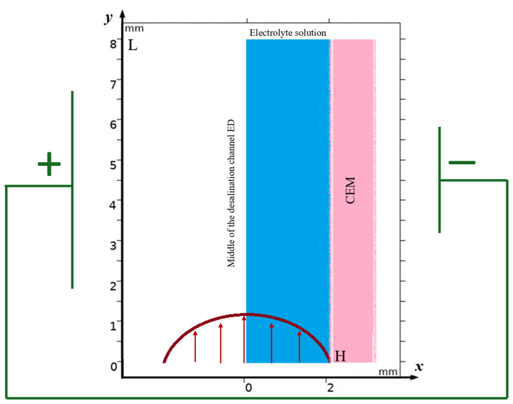
Figure 2.
Four basic channel configurations: (a) smooth CEM; (b) structured CEM surface with semicircular protrusions (radius 0.5 mm, period 1 mm); (c) structured surface with wing-shaped spacers (chord 0.68 mm, angle of attack 30°) placed at the membrane; (d) the same wings shifted into the solution bulk and upstream.
Figure 2.
Four basic channel configurations: (a) smooth CEM; (b) structured CEM surface with semicircular protrusions (radius 0.5 mm, period 1 mm); (c) structured surface with wing-shaped spacers (chord 0.68 mm, angle of attack 30°) placed at the membrane; (d) the same wings shifted into the solution bulk and upstream.
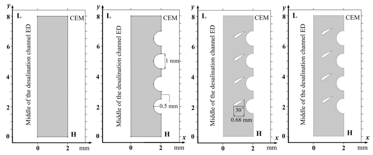
Figure 3.
Extended configurations (e)–(h): variations of the wing-spacer position (distance from the membrane and shift along the flow) at the same structured membrane surface.
Figure 3.
Extended configurations (e)–(h): variations of the wing-spacer position (distance from the membrane and shift along the flow) at the same structured membrane surface.
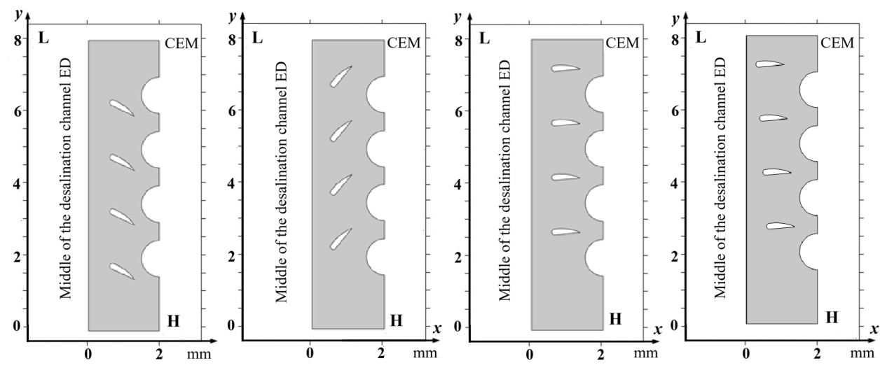
Figure 4.
Streamlines (white) and cation concentration fields at t = 280 s (Δφ = 1.4 V) for configurations (a)–(d). Red is the feed concentration, blue is the depleted near-membrane zone; the depleted layer visibly thins from (a) to (d).
Figure 4.
Streamlines (white) and cation concentration fields at t = 280 s (Δφ = 1.4 V) for configurations (a)–(d). Red is the feed concentration, blue is the depleted near-membrane zone; the depleted layer visibly thins from (a) to (d).
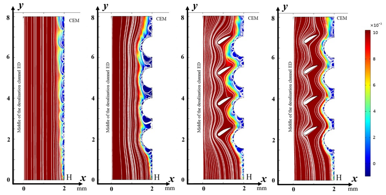
Figure 5.
Streamlines and cation concentration fields at t = 280 s for configurations (e)–(h). The combination of the structured surface and wing spacers steers the concentrated core flow onto the membrane and further thins the diffusion layer.
Figure 5.
Streamlines and cation concentration fields at t = 280 s for configurations (e)–(h). The combination of the structured surface and wing spacers steers the concentrated core flow onto the membrane and further thins the diffusion layer.
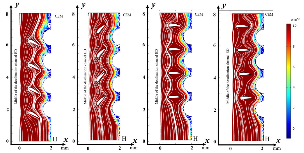
Figure 6.
Current–voltage characteristics of the eight channel configurations (potentiodynamic mode, sweep 5 mV/s, C₀ = 10 mol/m³). Dashed curves: configurations without wing spacers (a, b); solid curves: configurations with wing spacers (c)–(h). Three regimes are indicated: ohmic rise, limiting-current plateau, and overlimiting growth.
Figure 6.
Current–voltage characteristics of the eight channel configurations (potentiodynamic mode, sweep 5 mV/s, C₀ = 10 mol/m³). Dashed curves: configurations without wing spacers (a, b); solid curves: configurations with wing spacers (c)–(h). Three regimes are indicated: ohmic rise, limiting-current plateau, and overlimiting growth.
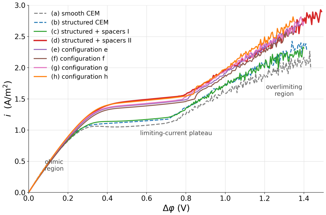
Figure 7.
Toward the 3D extension of the model: (a) three-dimensional geometry of the desalination cell bounded by the anion-exchange (AEM) and cation-exchange (CEM) membranes; (b) computed three-dimensional field of the cation concentration C₁ at t = 10 s—the depleted (blue) zone forms at the CEM and develops along the channel.
Figure 7.
Toward the 3D extension of the model: (a) three-dimensional geometry of the desalination cell bounded by the anion-exchange (AEM) and cation-exchange (CEM) membranes; (b) computed three-dimensional field of the cation concentration C₁ at t = 10 s—the depleted (blue) zone forms at the CEM and develops along the channel.
Disclaimer/Publisher’s Note: The statements, opinions and data contained in all publications are solely those of the individual author(s) and contributor(s) and not of MDPI and/or the editor(s). MDPI and/or the editor(s) disclaim responsibility for any injury to people or property resulting from any ideas, methods, instructions or products referred to in the content. |
© 2026 by the authors. Licensee MDPI, Basel, Switzerland. This article is an open access article distributed under the terms and conditions of the Creative Commons Attribution (CC BY) license (http://creativecommons.org/licenses/by/4.0/).
Copyright: This open access article is published under a Creative Commons CC BY 4.0 license, which permit the free download, distribution, and reuse, provided that the author and preprint are cited in any reuse.