

Submitted:
17 September 2026
Posted:
20 September 2026
You are already at the latest version
Abstract
Female pelvic-floor support is a coupled biomechanical system involving the vagina, uterus, pelvic connective tissues, ligaments, levator ani, and pelvic boundaries. Published finite-element studies demonstrate that changes in intra-abdominal pressure (IAP), tissue impairment, and pelvic geometry alter stress and displacement patterns. This study proposes a constraint-modulated load-transfer framework in which pressure-induced deformation is redistributed through the interconnected pelvic support structures toward posterior pelvic boundaries. Within this framework, three metrics are defined: geometric Poisson’s ratio (νg), structural Poisson’s ratio (νs), and composite Poisson’s ratio (νc). The proposed composite Poisson’s ratio (νc) is introduced as a candidate system-level outcome measure rather than an established clinical or validated numerical biomarker. No new experimental or original finite-element simulation outputs are generated in this work; all interpretations draw upon previously-published literature. This manuscript integrates published biomechanical evidence with a proposed finite element (FE) validation protocol without claiming unsupported original numerical stress or displacement results.
Keywords:
pelvic floor biomechanics
; intra-abdominal pressure
; finite element analysis
; Poisson effect
; pelvic organ prolapse
; load transfer
1. Introduction and Background
The female pelvic floor provides dynamic support to pelvic organs under changing mechanical conditions. Biomechanical reviews describe contributions from connective tissues, ligaments, and the levator ani, while finite-element studies demonstrate that pelvic support emerges from interactions among multiple structures rather than from a single tissue (Ashton-Miller & DeLancey, 2007; Easley et al., 2017). Subject-specific MRI-based FE models have also been used to compare simulated deformation with dynamic MRI measurements, providing a rigorous framework for quantitative model validation (Brandão et al., 2008; Saleme et al., 2011).
2. Theoretical Framework and Mechanical Problem
2.1. Load-Transfer Hypothesis
We hypothesize that the pelvic floor can be interpreted as a constrained load-transfer network. Under increased intra-abdominal pressure (IAP), local anatomical attachments and tissue continuity constrain deformation, while other regions undergo greater displacement. A published 2D FE study of a normal female pelvic floor found that, under increasing abdominal pressure, the mechanical axes of the cervix, middle/upper vagina, and levator ani showed a characteristic orientation toward the sacrum and coccyx, while the sacrum/coccyx, levator ani, and perineal body provided important support (Li et al., 2022). This published observation provides a biomechanical basis for the proposed posterior load-transfer concept.
2.2. Poisson-Type Deformation Metrics
The Poisson effect provides a useful mechanical language for describing coupled longitudinal and transverse deformation. However, pelvic tissues are heterogeneous, nonlinear, and anatomically constrained. Therefore, an apparent deformation ratio measured from the intact pelvic assembly differs from a constitutive parameter assigned to an isolated tissue.
- Geometric Poisson’s ratio (νg): A proposed imaging-derived ratio describing apparent transverse and longitudinal anatomical deformation during functional loading.
- Structural Poisson’s ratio (νs): A constitutive material parameter used in a tissue-level FE model, selected from tissue-specific experimental evidence.
- Composite Poisson’s ratio (νc): A proposed system-level ratio calculated from prespecified deformation measures of a constrained anatomical assembly.
3. Analysis of Published Finite Element Evidence
Li et al. (2022) constructed an MRI-based 2D FE model of a healthy female pelvic floor and simulated abdominal pressure conditions of 60, 99, 168, and 208 cmH2O. The reported maximum displacement of the system was 10, 14, 21, and 25 mm, respectively, while maximum stress increased from 0.1943 to 0.6275 MPa. Additional FE studies evaluated 60, 99, and 168 cmH2O and reported pressure-dependent changes in stress and displacement (Guo et al., 2016). Whole-pelvic support models in ANSYS likewise demonstrated pressure-dependent changes with greater upper-vaginal displacement under high IAP (Chen et al., 2022).
Recent work provides direct evidence for pressure–constraint interactions in injured pelvic floors. At IAP 83.9 cmH2O, a 2026 FE study reported cervical descent increasing from 14.3 to 20.9 mm when genital hiatus increased from 10 to 40 mm (Zheng et al., 2026). Another 2026 comparative FE study investigated progression of pathological prolapse under a 75% posterior-vaginal-wall injury condition (Si et al., 2026).
4. Proposed Conceptual Models and Validation Frameworks
4.1. Conceptual Load-Transfer Mechanism Representation
To conceptualize the hypothesized sequence of load redistribution, Figure 1 presents the three quantifiable faces of Poisson’s ratio and the underlying system-level biomechanics. As illustrated in Figure 1, the theoretical framework links organ-level kinematics (νg) and tissue constitutive behavior (νs) into an overarching composite metric (νc).
4.2. Finite Element Validation Schematic
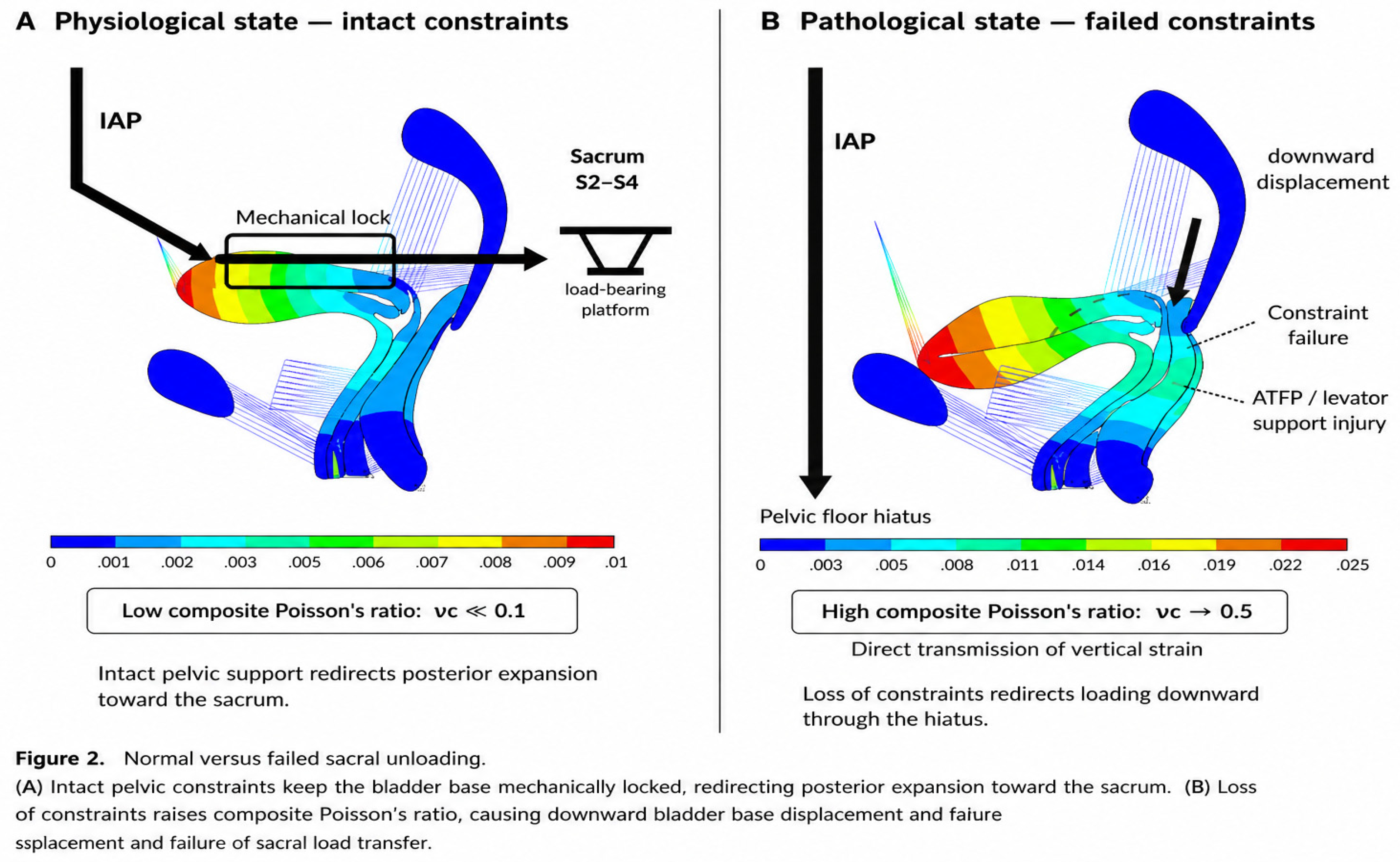
To establish a reproducible numerical protocol, Figure 2 defines the comparative validation schematic between normal and impaired states. As depicted in Figure 2, intact structural constraints convert vertical abdominal pressure into horizontal posterior load redirection, whereas constraint failure leads to direct vertical strain transmission and Hiatal herniation.
4.3. Protocol Endpoints and Pressure Conditions
A future validation study should reconstruct a subject-specific 2D or 3D pelvic model from high-resolution MRI and explicitly report geometry, segmentation, mesh convergence, constitutive laws, contact definitions, boundary conditions, and solver settings (Zhou et al., 2023; Zhao et al., 2019; Martins et al., 2007; Liu et al., 2026).
- Primary kinematic endpoints: Cervical, vaginal-wall, levator, and perineal-body displacement.
- Mechanical endpoints: Tissue stress/strain distributions and resultant force directions.
- Exploratory endpoint: Composite Poisson’s ratio (νc) calculated from prespecified geometry.
- Validation endpoint: Agreement between model-predicted displacement and dynamic-MRI measurements.
5. Synthesis, Limitations, and Conclusions
5.1. Limitations and Data Provenance
Precise FE stress, displacement, and νc values from preliminary drafts have been re-evaluated to ensure strict data provenance. Future numerical evaluations will require raw file verification, mesh convergence analysis, and solver documentation.
5.2. Conclusion
Published FE studies support the existence of pressure-dependent deformation, stress redistribution, and altered pelvic support under structural impairment. These observations can be integrated into a constraint-modulated load-transfer framework and systematically evaluated using subject-specific FE models.
Author Contributions
Conceptualization, J.S. and T.Y.; formal analysis, J.S. and Z.L.; visualization, J.S. and X.L.; writing-original draft preparation, J.S.; writing-review and editing, all authors. All authors have read and agreed to the submitted version of the manuscript.
Funding
This research received no external funding.
Institutional Review Board Statement
Not applicable.
Informed Consent Statement
Not applicable.
Data Availability Statement
No new data were created or analyzed in this study. Data sharing is not applicable to this article.
Conflicts of Interest
The authors declare no conflict of interest.
References
- Li, S.; Zhang, Y.; Wang, L.; et al. Two-dimensional equivalent mechanical modeling and finite element analysis of normal female pelvic floor system. Zhonghua Yi Xue Za Zhi 2022, 102(28), 2175–2181. [Google Scholar] [CrossRef] [PubMed]
- Zheng, Q.; Li, L.; Gao, Z.; Shen, J.H.; Yao, T.Q. Biomechanical effects of intra-abdominal pressure and genital hiatus on the pelvic floor in initial injury. Proc. Inst. Mech. Eng. H. 2026, 240(3), 143–152. [Google Scholar] [CrossRef] [PubMed]
- Si, S.; Chen, Y.; Zhao, X.; et al. Biomechanics of pathological pelvic floor: Finite element comparative analysis of the prolapsed pelvic floor. Clin. Biomech. 2026, 112, 106180. [Google Scholar] [PubMed]
- Chen, L.; Song, Y.; Wang, V.; et al. Relationship between high intra-abdominal pressure and compliance of the pelvic floor support system in women without pelvic organ prolapsed: a finite element analysis. BMC Womens Health 2022, 22(1), 345. [Google Scholar] [PubMed]
- Zhou, X.; Chen, N.; Wang, B.; Yang, J.; Liu, H.; Zhang, X.; Li, Y.; Liu, L.; Wu, Y. Creation of the biomechanical finite element model of female pelvic floor supporting structure based on thin-section high-resolution anatomical images. J. Biomech. 2023, 146, 111399. [Google Scholar] [CrossRef] [PubMed]
- Zhao, Y.; Zhang, C.; Qiu, L.; et al. Development of anatomically based customizable three-dimensional finite-element model of pelvic floor support system: POP-SIM1.0. Int. Urogynecol J. 2019, 30(12), 2089–2097. [Google Scholar] [PubMed]
- Ashton-Miller, J.A.; DeLancey, J.O.L. Functional anatomy of the female pelvic floor. Ann. N Y Acad. Sci. 2007, 1101, 266–296. [Google Scholar] [CrossRef] [PubMed]
- Easley, D.C.; Abramowitch, S.D.; Moalli, P.A. Female pelvic floor biomechanics: bridging the gap. Curr. Opin. Urol. 2017, 27(3), 262–267. [Google Scholar] [CrossRef] [PubMed]
- Brandão, S.; Parente, M.P.; da Silva-Filho, A.L.; et al. Subject specific finite elasticity simulations of the pelvic floor. J. Biomech. 2008, 41(13), 2826–2833. [Google Scholar] [CrossRef] [PubMed]
- Saleme, C.S.; Parente, M.P.L.; Natal Jorge, R.M.; Pinotti, M.; Silva-Filho, A.L.; Roza, T.; Mascarenhas, T.; Tavares, J.M.R.S. An approach on determining the displacements of the pelvic floor during voluntary contraction using numerical simulation and MRI. Comput Methods Biomech. BioMed Engin 2011, 14(4), 365–370. [Google Scholar] [CrossRef] [PubMed]
- Guo, M.; Li, D.; Xu, Q.; et al. Stress distribution and deformation of uterosacral ligament and cardinal ligament under different working conditions simulated by the finite element model. J. Med. Biomech. 2016, 31(1), 45–51. [Google Scholar] [PubMed]
- Martins, J.A.C.; Pato, M.P.M.; Pires, E.B.; Natal Jorge, R.M.; Parente, M.; Mascarenhas, T. Finite element studies of the deformation of the pelvic floor. Ann. N Y Acad. Sci. 2007, 1101, 316–334. [Google Scholar] [CrossRef] [PubMed]
- Liu, X.; Wang, H.; Zhang, R.; et al. Biomechanical finite element simulation of the pelvic organs under dynamic loading and validation against experimental data from magnetic resonance imaging. Med. Eng. Phys. 2026, 125, 104110. [Google Scholar] [PubMed]
Figure 1.
Three quantifiable faces of Poisson’s ratio in pelvic floor biomechanics. (A) Geometric Poisson’s ratio (νg) derived from in-vivo organ displacement during Valsalva. Sub-panel A: Resting state in nulliparous female; Sub-panel B: Sagittal magnetic resonance imaging during Valsalva maneuver; Sub-panel C: Vector schematic showing displacement of cervix, vagina, and levator ani. The vertical downward blue arrow represents primary downward intra-abdominal pressure (IAP); horizontal double-headed blue arrows indicate transverse displacement (Δx). (B) Structural Poisson’s ratio (νs) representing intrinsic tissue material behavior (ν ≈ 0.5). (C) Composite Poisson’s ratio (νc) describing system-level deformation of the constrained bladder-pelvic floor complex. Large yellow downward arrow represents vertical abdominal load; curved red arrow demonstrates redirected load transfer toward posterior pelvic boundaries under intact constraints. Abbreviations: UT, Uterus; B, Bladder; V, Vagina; R, Rectum; LE, Levator Ani; P, Pubic Bone; PB, Perineal Body. Note: Visual schematic integrated and adapted based on dynamic MRI and finite element simulation data from published literature [Li et al., 2022; Si et al., 2026].
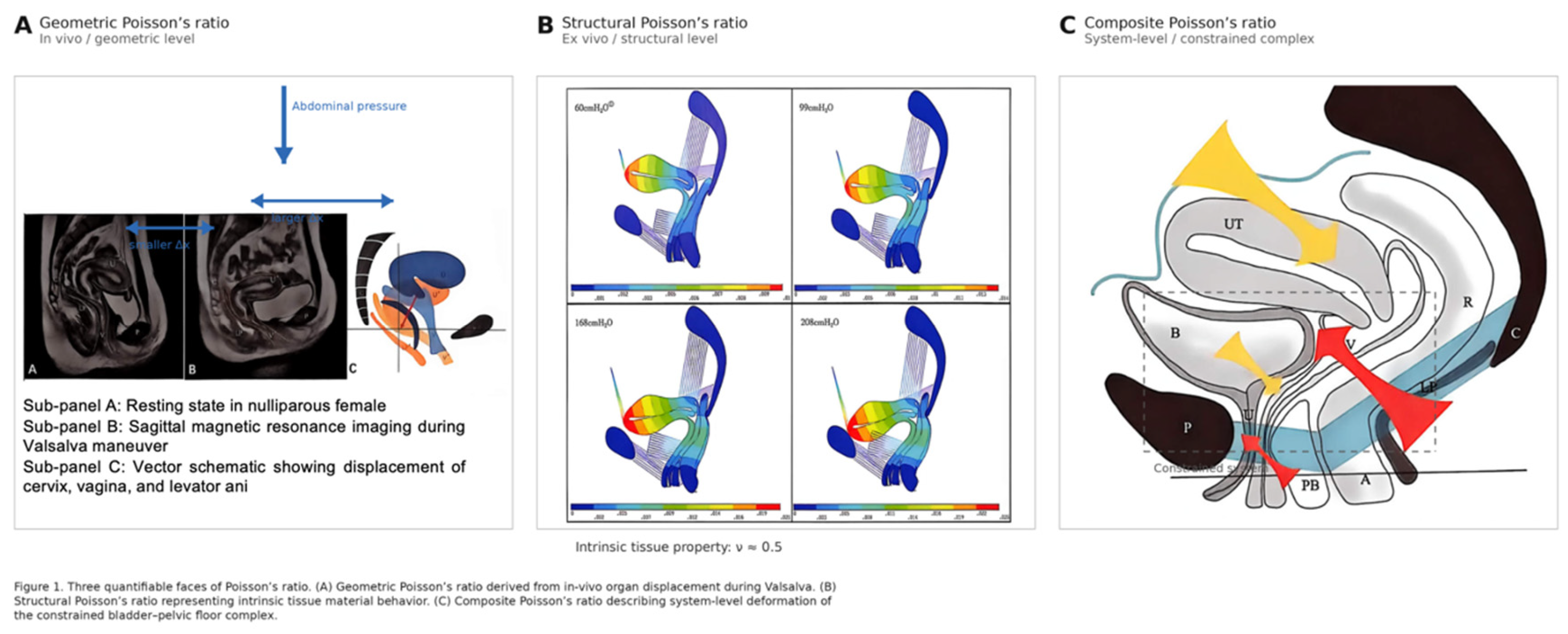
Figure 2.
Normal versus failed sacral unloading. (A) Physiological state — intact constraints: Top left black downward arrow represents initial vertical intra-abdominal pressure (IAP) input; horizontal rightward black arrow indicates horizontal load redirection toward S2–S4 sacral platform (“Sacral Unloading”), maintaining νc ≪ 0.1. (B) Pathological state — failed constraints: Long left vertical black arrow represents unmitigated vertical IAP penetration caused by loss of structural constraints; right incline short black arrow highlights downward displacement of bladder base and tissue herniation through pelvic floor hiatus (νc → 0.5).Abbreviations: IAP, Intra-Abdominal Pressure; ATFP, Arcus Tendineus Fasciae Pelvis. Note: Visual schematic synthesized based on published numerical pelvic floor models [Zheng et al., 2026; Si et al., 2026].
Disclaimer/Publisher’s Note: The statements, opinions and data contained in all publications are solely those of the individual author(s) and contributor(s) and not of MDPI and/or the editor(s). MDPI and/or the editor(s) disclaim responsibility for any injury to people or property resulting from any ideas, methods, instructions or products referred to in the content. |
© 2026 by the authors. Licensee MDPI, Basel, Switzerland. This article is an open access article distributed under the terms and conditions of the Creative Commons Attribution (CC BY) license.
Copyright: This open access article is published under a Creative Commons CC BY 4.0 license, which permit the free download, distribution, and reuse, provided that the author and preprint are cited in any reuse.