
Submitted:
30 July 2026
Posted:
31 July 2026
You are already at the latest version
Abstract
Numerous landslides appeared in the region of Atsuma (Hokkaido, Japan) as a result of the 2018 Hokkaido Eastern Iburi Earthquake. Despite their devastating consequences, the emergence of mass movements may provide a unique opportunity to gain insight into specific chapters of Earth’s history by exposing new natural outcrops and revealing rock strata. In the region, geological formations, including the studied Middle Miocene Kawabata Formation, composed primarily of sedimentary rocks, reflect various deep-sea environments, especially the continental slope and basin plain of a foreland basin. For such a reason, the exposed bedding plane consisting of polygonal features in an outcrop formed at the scarp of a landslide aroused interest. Mud cracks or desiccation marks often form in the tidal zone due to exposure to the subaerial environment, but not in the aforementioned deep-sea facies. An additional series of evidence of wet and dry cycles in a near-shore (coastal) environment was revealed, such as limonite grain coatings and hypocoatings, and biotite exfoliation. Based on that evidence, a new Middle Miocene facies, a newly discovered stratigraphic member, was proposed in the Kawabata Formation, indicating a tidal palaeoenvironment.
Keywords:
Kawabata Formation
; tidal facies
; mud cracks
; desiccation marks
; polygonal features
; limonite
; goethite ooid
; biotite exfoliation
1. Introduction
To understand the importance of the findings (desiccation marks, or mud cracks) exposed on a randomly discovered bedding plane surface in a Miocene sediment sequence, it is crucial to briefly summarize the evolution of Hokkaido, the northernmost of the main islands of Japan.
In present-day plate tectonic settings, Hokkaido Island lies on the North American plate (specifically the Okhotsk plate) and faces the Eurasian plate (Amur plate) (Figure 1A). Such a tectonic setting, consisting of a plate boundary running at the eastern margin of the Sea of Japan, became active from the Quaternary period. However, prior to reaching the present-day plate tectonic setting, the complex structural, geological, and paleoenvironmental evolution of the region can be introduced [5].
The oldest pre-Neogene basement formations in the region date to the Late Paleozoic (Carboniferous and Permian) and belong to the Oshima Belt, one of the region's tectonostratigraphic belts. The Oshima belt is part of the mainly north-south-aligned belt system in the region, consisting of the Oshima, Sorachi-Yezo, Hidaka, Tokoro, and Nemuro belts, forming a complex accretionary system with progressively younger structural geological units eastward (Jurassic, Cretaceous, and Paleogene accretionary complexes). The Oshima and Sorachi-Yezo belts belong to the Honshu (NE Japan) arch-trench system, while the latter two, the Tokoro and Nemuro belts, are attributed to the Kuril Arc. The Hidaka Belt stands “in between”, with parts connecting to the Honshu arch-trench system, and others to the Kuril Arc [5,6]. Such a setting defines the tectonic division of Hokkaido Island: the so-called Honshu and Kuril terranes [5,6] (Figure 1A and B).
The initial pre-Neogene plate tectonic setting changed during the Miocene, when the major tectonic boundary moved through the present-day central Hokkaido, resulting in the formation of a collision zone between the Kuril and Honshu (NE Japan) arcs, accompanied by tectonic processes, such as rotation of eastern Hokkaido, fold and thrust belt formation in central Hokkaido, along with thrust faults, and dextral share zones triggered metamorphism and the exhumation of various blocks (e.g. foreland basin deposits and Miocene granulites) [5].
Considering the main sedimentary facies types, the frontal parts of the collision zone comprise a foreland sedimentary basin or foredeep. The sediments of the basin can be found incorporated, e.g., in the fold-and-thrust belt of central Hokkaido. The sediments of the foredeep, dating from the Late Oligocene (Erimo Fm.) to the Pliocene (e.g. Moebetsu Fm. and Nibudani Fm.), the Miocene formations (e.g., Kawabata Fm. and Karumai Fm.) mainly characterized by deep-sea sediments, especially various turbidite-related types (e.g., sheet-flow and slope-apron turbidites), fed by uplift and extensive erosion in the region [5,6,7,8,9,10,11,12] (Figure 1C).
As it was suggested above, the Miocene formations mainly consist of turbidites, and for this reason, finding polygonal features, namely desiccation marks (mud cracks), generally appear, e.g., in near-shore environments (tidal facies), indicating subaerial exposure, in deep-sea sediments (whether they are deep-sea or not) has raised attention (Figure 2).
The goal of this study is to introduce the feature, present preliminary results from scanning electron microscopy, and discuss the importance of this finding for the future reconstruction of Miocene sedimentary environments that appeared around the Japanese archipelago.
2. Site and Sampling
The sampled profile is located near Atsuma city (Hokkaido, Japan), southeast of the Mizuho Dam, at coordinates 42.83206° N, 141.92766° E (Figure 1, Outcrop A). Among the Miocene sediments, Kawabata Fm. (also called Fureoi Fm) is one of the most commonly appearing ones, indicating two facies related to submarine fan, continental slope, and the deep-sea foreland basin environment: i) channel levee facies, and ii) sheet flow turbidite. The former (channel levee) facies are composed of thick sandstone units, and the alteration of mudstone members and sandstone horizons represents the Tc zone of a Bouma sequence. The latter (sheet-flow turbidite) facies consists of sand and mudstone members in rhythmic alternation [12].
Near the studied profile, several outcrops, mainly roadcuts, appear, consisting of the Kawabata Fm (Figure 2A,B). The exposed profiles uniformly show a 40-45° S dip angle with a strike of E. The upper section of the Kawabata Fm (Middle Miocene) often consists of disaggregated (physically weathered), debris-like units with barely visible stratification, all covered by a discordant cambisol-like paleosol (P1) horizon with recognizable AB, Bw, and C pedogenic sub-horizons. Depending on the paleotopographical position, the paleosol, or some of its sub-horizons, may be eroded, or covered by loose sediments (S1) and the recent, P0 topsoil (Figure 2A). The extensively weathered parts, the buried paleosol horizon, the loose sediments may represent surface processes appeared during cold and dry glacial (physical weathering and terrestrial clastic sedimentation) and more humid and mild interglacial periods (pedogenesis) of the (Late) Pleistocene and the Holocene.
The studied profile, an outcrop exposed by a landslide, and its head or main scarp. Despite its poor condition (i.e., covered by debris), the mass movement, with its slide surface quasi-parallel to the dipping bedding plane of the sediment units of the Kawabata Fm, exposed at least three generations of polygonal features (mud cracks or desiccation marks) (Figure 2C,D).
The observation of desiccation marks raised further attention because such features commonly appear in near-shore environments but turbidite/deep-sea facies (as Kawabata Fm. was originally defined) [13,14,15]. The generation of a polygonal structure suggests that such “subaerial exposure events” might appear periodically, even bearing the mark of early pedogenesis (regolith formation). Such assumptions led to sampling the paleosurface and taking a polygonal block for further laboratory studies (Figure 2E).
3. Methods
Four vertically oriented thin sections were prepared from the polygonal block taken from the field (Figure 2E and 3A–D) for preliminary analysis.
During the general description and (surface) mesomorphological study of the specimens (which examines features between the microscopic and macroscopic scales), a stereomicroscope (Kenis, Japan) equipped with a Ramu-01 microscope camera (Japan) was used.
Subsequently, the well-polished samples were studied using a JEOL JSM-6480LAII scanning electron microscope (SEM) equipped with an energy-dispersive X-ray spectroscope (EDS) for chemical analyses at the Department of Planetology, Kobe University (Japan). EDS measurements were obtained at 15 kV and 0.4 nA with a working distance of 10 mm. The collection time for the spectra was 100 sec. Data corrections were made using the ZAF method routine, embedded in the software package of Analysis Station 3.91 developed by JEOL Co., with well-established natural/synthesized materials distributed by JEOL Co. as chemical standards.
4. Results
4.1. Mesomorphology – Binocular Microscopy
The mesomorphological description of the sampled section revealed microstratification in the studied samples, comprising four characteristic layers.
The uppermost microlayer (Layer 1; Figure 3) is a ~5 mm thick fine-grained, light (greyish) orange - yellow (Munsell color; wet: 7.5YR6/6, and dry: 10YR8/6) silty clay horizon, the possible remnant of a mudstone member of the alternating mudstone–sandstone layers. A network of smaller cracks is visible in this unit.
The underlying 2.5-3 cm thick layer (Layer 2; Figure 3) is a coarser, sandy unit, representing the sandstone member of the characteristic sandstone-mudrock heterolithic sequence. Based on its physical characteristics (color and texture) it can be separated into an upper grey (2a1 and 2a2; Figure 3) and lower (reddish) brown-light brown (wet: 7.5YR4/3 and dry: 7.5YR6/3) sandstone unit (2b; Figure 3). The upper, grey microunit (2a) can be separated further into two subsections: an upper ~1 cm thick, middle grey unit (wet: 10YR5/1 and dry: 2.5Y6-7/1; 2a1; Figure 3), and a lower, thinner (~0.5 cm), lighter colored one (wet: 10YR6/1, and dry: 2.5Y8/1; 2a2; Figure 3D). This subunit only appeared in one thin section (Figure 3D), which may suggest that it is a phenomenon appearing scattered in the sediment (e.g. lenticular bedding).
The underlying unit is a red (wet: 7.5YR4/3, and dry: 7.5YR6/3) sandy microlayer, connecting to the 2a unit with a gradual boundary (2b; Figure 3A,B,D).
The lowermost unit only appears as millimeter-thick fragments, consisting of fine, light colored (wet: 10YR8/3, and dry: 10YR8/1) silty clay unit (Layer 3; Figure 3).
There are two types of commonly appearing mesomorphological features in the studied thin sections: i) network of quasi-horizontal and vertical cracks, and ii) the appearance of various limonite (goethite) precipitation features.
The formation of the former, i.e., the network of horizontal and vertical cracks, seems to be strongly related to material differences and sedimentary structure/boundaries observed in the studied thin sections. A few longer cracks appear in the lower, coarser sediment section of the samples, the horizontal ones seemingly following the boundaries between various sedimentary microunits (Figure 3D,E). The uppermost, finer sediment unit of the sample consists of a well-developed network of shorter, finer cracks, connecting the top of the underlying coarser sediment and the supposed polygonal paleosurface (Figure 3).
The latter, i.e., the limonite precipitation features, appears in various forms, such as colorings (Figure 3A, B and D, 2b subunit), precipitation fronts (Figures C, D, and E), and hypocoatings along the cracks (Figure 3).
Microlamination with sub-millimeter-thick laminas might also appear in some thin sections, e.g., in thin section A (Figure 3, A, between 15 and 20 mm depth). Such a feature is unique among the studied samples.
4.2. Scanning Electron Microscopy and Energy-Dispersive X-Ray Spectroscopy
Along with the basic description of the samples, the preliminary SEM and EDS studies primarily focused on observing index minerals and features that may indicate changes in the sedimentary environment related to the development of the polygonal structure.
The most common minerals observed in the studied location are quartz, plagioclase feldspar (e.g., albite), biotite, and goethite (limonite) (Figure 4 and Figure 5).
The roundness of the observed (quartz) grains varies between sub-angular and very angular, with various sphericity (Figure 4).
Regarding secondary mineral formation, the SEM micrographs support the observations of limonite appearance. Goethite (limonite) grain coatings appeared commonly in the petrofabric (Figure 4 and 5A, B), along with pore and crack infills (Figure 4)
Considering mineral alteration processes, exfoliation of mineral cleavage and deformation of the sheets was observed in almost all the biotite fragments found in the samples (Figure 4 and 5C)
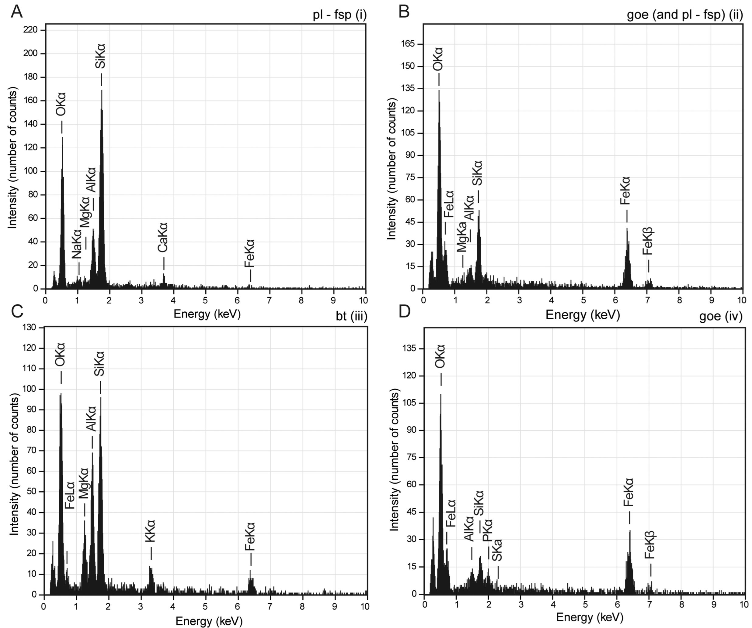
Features resembling pyrite framboids appear as well (Figure 4B and C), but based on the EDS analysis, they turned out to be goethite/limonite pseudomorphs of pyrite, considering their chemical composition (Figure 5D). Concentric (weathering) structure and the detachment of the concentric outer and inner sections were also recognized inside the putative framboids (Figure 4A and B).
5. Discussion
5.1. Indicators of Various Facies and Environment Components
Besides the polygonal structures (mud cracks or desiccation marks) observed in the field, which are primary indicators of exposure to a subaerial environment, studying various microscopic features may provide further information on changes in the sedimentary environment.
Network of cracks. The network of quasi-vertical and horizontal cracks observed at the meso- and microscopic levels indicates that both the fine-grained upper and coarser, sandy lower unit were influenced by subaerial exposure and desiccation processes (Figure 3 and Figure 4).
Goethite/limonite. The high variety of goethite (limonite) appearance and its meso- and micromorphology, including colorings, precipitation fronts (bands), grain coatings, hypocoatings, and infills (pores and fractures) (Figure 3 and Figure 4) indicate an oxidative environment with a migration of iron-(super)saturated solutions, following the pore structure and crack network toward the surface. This migration and oxidative environment might have developed due to periodic or permanent subaerial exposure and intensified evaporation (i.e., redox fluctuation – wetting and drying phases) [16]. This agrees with the formation environment of desiccation marks.
Biotite. The observed biotite grains show the initial phase of weathering, characterized by hydration, delamination, and exfoliation of the biotite sheets, which often occur during wet-dry sedimentary or pedogenic cycles in a subaerial environment (Figure 4) [17] but are less characteristic, e.g., in deep-sea facies.
Goethite/limonite pseudomorph of pyrite framboids. Authigenic pyrite formation is a common process in anoxic sedimentary environments, resulting in the development of various mineral morphologies [18], including pyrite framboids, reflecting an early stage of anoxic diagenesis [19]. Such an anoxic environment changed during the evolution of the sediment sequence, resulting in the alteration of pyrite into goethite in a more oxidative environment. The indirect indication of pyrite would fit the deep-sea sedimentary environment thought to dominate the development of the Kawabata Fm.
Goethite spherules. Given the internal structure of the putative framboids observed in SEM (Figure 4C), the formation of goethite spherules may be a possible alternative. The formation of these spherules may also be explained by surface (wave and current agitation – e.g., goethite ooids) and subsurface (goethite concretions) processes. Among many ways, ooid formation can be explained as mechanical (rolling) accretion of material in a shallow marine environment where goethite ooids are continuously rolled and grow [20]. During this process, apatite may also be adsorbed (chemical processes on the goethite ooid’s surface - ligand exchange; [21]). This would also explain the appearance of phosphate on the EDS plot (Figure 5D).
Please note that mechanical accretion and the development of concretions are just a few among many processes which may result in the formation of goethite spherules (e.g., [20]), but the detailed study of the ooids/spherules appearing in the studied sequence is out of the focus of this preliminary study.
5.2. Implications - New Facies and Potential Stratigraphic Member of Kawabata Fm
All the preliminary findings point toward a sedimentary facies where wet and dry periods repeatedly formed the paleoenvironment with cycles of water-covered and subaerial exposure phases. The indicators of a near-shore/shore, tidal-zone facies seem to contradict common knowledge about the Kawabata Formation, namely that the formation represents a deep-sea foreland basin environment (even reaching 1000 m depth [7,8]) characterized by sheet-flow turbidites (Figure 7). In addition, the observation of a series of polygonal paleosurfaces (PS1, PS2 and PS3; Figure 2D) suggests that the subaerial exposure was not a sole event but a repeated series of events during the Middle Miocene.
We may ask whether we need to re-evaluate the commonly accepted view about the Kawabata Formation, i.e., that it represents channel levee and sheet-flow turbidite facies, developed in a deep-sea environment [7,8,11,12]. Confusion might occur between some sections of alternating sandstone and mudstone layers of the sheet flow turbidites and alternating sand and mudstone layers of tidal sediments when the studied facies types do not carry many of the key diagnostic features of turbidites or when features are not clearly recognizable (e.g., due to the condition of the studied outcrops and due to the lack of the exposure of the depositional/sedimentation bed).
Figure 6.
The generally accepted facies and sedimentary paleoenvironment reconstruction of the Middle Miocene based on the characteristics of the Kawabata Formation (A) [5,6,12] and the proposed additional member of the formation, based on the newly discovered features, described in this study (B).
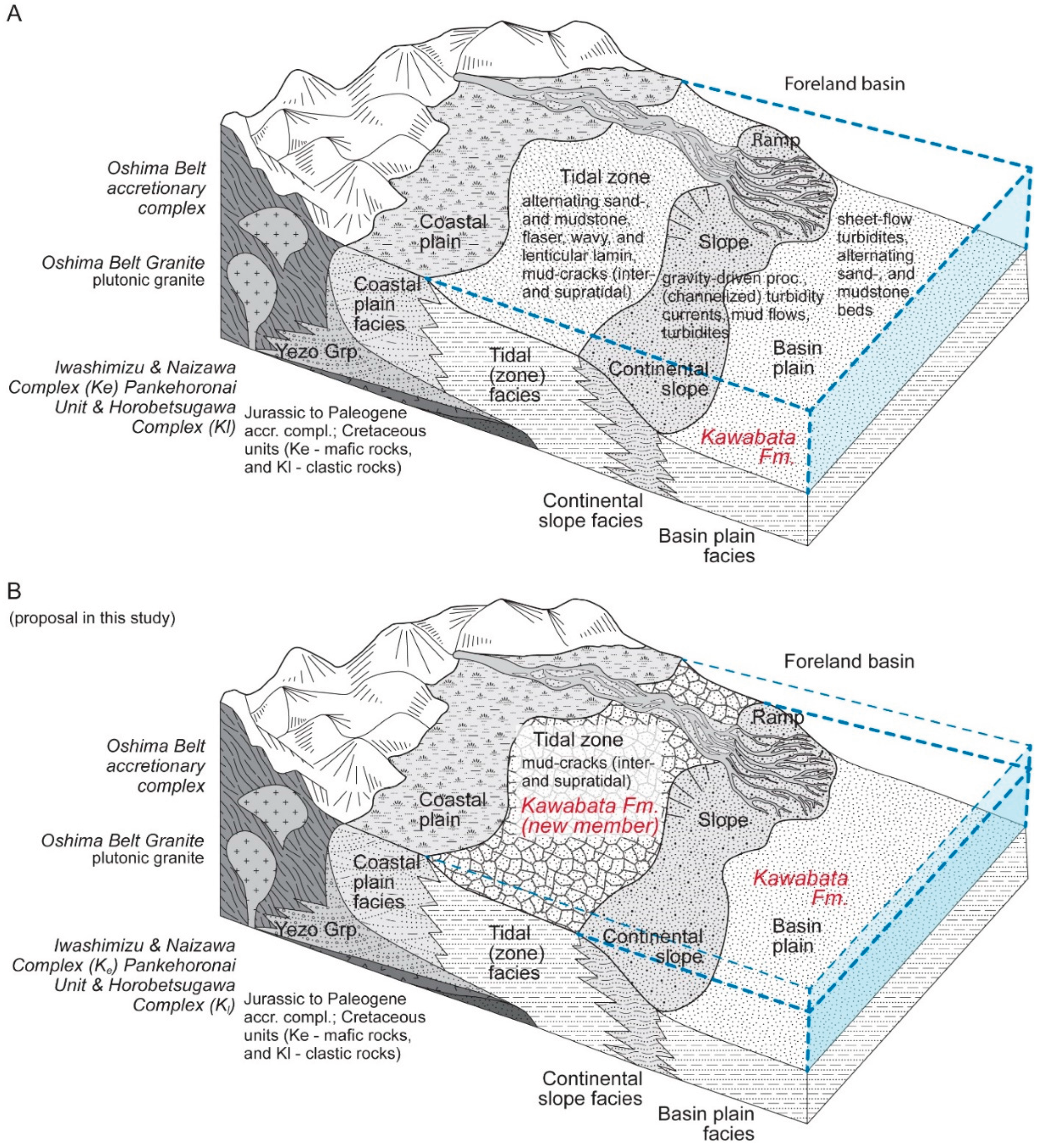
Along with the observed indicators of subaerial exposure, tidal facies and near-shore paleoenvironment, additional evidence from the literature may support our findings. Plant fragment-rich horizons were observed and interpreted as a result of long-distance transportation from a terrestrial environment by density flows and deposited in a deep-sea environment [22]. The existence of a new facies type in Kawabata Fm. may provide an alternative explanation, suggesting that the deposition of plants might happen in e.g., a shore or near-shore environment (e.g., a lagoon) but in a deep-sea environment following a series of re-deposition (which might prevent the development of tens of centimeter/meter- thick fossil plant-rich layers). Unfortunately, without reinvestigation of the profiles consisting of plant fossil-rich layers, this is merely speculation and far from being clear evidence.
Despite the series of evidence indicating subaerial exposure, it may be unlikely that the whole Kawabata Fm (especially the Amagiri Sandstone and Mudstone Member; [8]) needs to be reinterpreted, but undoubtedly, a new facies, a new potential lithostratigraphic member has been introduced in this study, which has to be taken into account during e.g. future geological mapping and Miocene paleoenvironment reconstructions from the Hokkaido region (Figure 7).
6. Conclusion
The discovery of polygonal features (mud cracks or desiccation marks) in an exposed bed of the Kawabata Formation, a formation known as deep-sea turbidite facies, led to a proposal of a new facies along the known ones representing a near-shore (coastal) tidal environment.
Beyond the discovery of a new facies of the Kawabata Formation, the appearance of such a feature may imply a significant change in the sea level triggered by i) extensive vertical movements in the accretionary prism developing in the region, and/or ii) pre-Pleistocene sea level drops triggered by e.g., Miocene cooling events. Such processes may be revealed by future and more detailed research of the newly introduced member of the Kawabata Formation.
Author Contributions
Conceptualization, B.B.; methodology, B.B.; formal analysis, B.B., C.G.,T.K.; investigation, B.B., R.N.; writing—original draft preparation, B.B.; writing—review and editing, B.B., C.G.; visualization, B.B. All authors have read and agreed to the published version of the manuscript.
Funding
This research received no external funding.
Data Availability Statement
Research data are available upon request to the corresponding author.
Conflicts of Interest
The authors declare no conflicts of interest.
Acknowledgments
We thank the anonymous reviewers for their constructive comments.
Abbreviations
The following abbreviations are used in this manuscript:
| SEM | scanning electron microscope |
| EDS | energy-dispersive X-ray spectroscope |
| Fm | formation (as stratigraphic unit) |
| EMi | Early Miocene |
| E/MMi | Early/Middle Miocene |
| MMi | Middle Miocene |
| LMi/EPl | Late Miocene / Early Pliocene |
| M/LPe | Middle/Late Pleistocene |
| LPe/Hol | Late Pleistocene / Holocene |
| Hol | Holocene |
| PS1, PS2, PS3 | Polygonal surface (generation 1 to 3) |
| P0 | Recent (surface) soil |
| P1 | Pleistocene (cambisol-like) paleosol |
| S1 | Pleistocene/Holocene sediment unit |
| BA | transitional soil horizon |
| Bw | weathered subsoil layer |
| Bw-C | transition horizon between Bw and C (parent material of the soil) |
| ab | albite |
| ani | anilite |
| bt | biotite |
| fsp | feldspar |
| goe | goethite |
| pl | plagioclase |
| qtz | quartz |
References
- Iwasaki, T.; Ozel, O.; Moriya, T.; Sakai, S.I.; Suzuki, S.; Aoki, G.; Maeda, T.; Iidaka, T. Lateral structural variation across a collision zone in central Hokkaido, Japan, as revealed by wide-angle seismic experiments. Geophys. J. Int. 1998, 132, 435–457. [Google Scholar] [CrossRef]
- Taira, A. Tectonic evolution of the Japanese island arc system. Annu. Rev. Earth Planet. Sci. 2001, 29, 109–134. [Google Scholar] [CrossRef]
- Takahashi, Y.; Shimura, T.; Kato, S. Plutonic and metamorphic rocks in the southern Hidaka metamorphic belt, Hokkaido. J. Geol. Soc. Jpn. 2018, 124, 399–411. [Google Scholar] [CrossRef]
- GeomapNavi; Geological Survey of Japan; AIST. GeomapNavi (Geological map display system). National Institute of Advanced Industrial Science and Technology. Available online: https://gbank.gsj.jp/geonavi/geonavi.php#6,38.247,137.000 (accessed on 11. 03. 2026).
- Ueda, H. Hokkaido, In: The geology of Japan; Moreno, T., Wallis, S., Kojima, T., Gibbons, W., Eds.; The Geological Society: London, 2016; pp. 201–221. [Google Scholar]
- Ueda, H. Accretion and exhumation structures formed by deeply subducted seamounts in the Kamuikotan high-pressure/temperature zone, Hokkaido, Japan. Tectonics 2005, 24, TC2007. [Google Scholar] [CrossRef]
- Kawakami, G.; Yoshida, K.; Usuki, T. Preliminary study for the Middle Miocene Kawabata Formation, Hobetsu district, central Hokkaido, Japan; special reference to the sedimentary system and the provenance. J. Geol. Soc. Jpn. (in Japanese with English abstract). 1999, 105, 673–686. [Google Scholar] [CrossRef]
- Kawakami, G.; Shiono, M.; Kawamura, M.; Urabe, A.; Koizumi, I. Stratigraphy and depositional age of the Miocene Kawabata Formation, Yubari Mountains, central Hokkaido, Japan. J. Geol. Soc. Jpn. (in Japanese with English abstract). 2002, 108, 186–200. [Google Scholar] [CrossRef]
- Kawakami, G.; Arita, K.; Okada, T.; Itaya, T. Early exhumation of the collisional orogen and concurrent infill of foredeep basins in the Miocene Eurasian–Okhotsk Plate boundary, central Hokkaido, Japan: inferences from K–Ar dating of granitoid clasts. Isl. Arc 2004, 13(2), 359–369. [Google Scholar] [CrossRef]
- Kawakami, G.; Ohira, H.; Arita, K.; Itaya, T.; Kawamura, M. Uplift history of the Hidaka Mountains, Hokkaido, Japan: a thermochronologic view. J. Geol. Soc. Jpn. 2006, 112, 684–698. Available online: www.jstage.jst.go.jp/article/geosoc/112/11/112_11_684/_pdf. [CrossRef]
- Kawakami, G. Foreland basins at the Miocene arc-arc junction, central Hokkaido, northern Japan. In Mechanism of Sedimentary Basin Formation-Multidisciplinary Approach on Active Plate Margins; Itoh, Y., Ed.; InTech, 2013; pp. 131–152. [Google Scholar] [CrossRef]
- Itoh, Y.; Tamaki, M.; Takano, O. Rock Magnetic Properties of Sedimentary Rocks in Central Hokkaido—Insights into Sedimentary and Tectonic Processes on an Active Margin. In Mechanism of Sedimentary Basin Formation: Multidisciplinary Approach on Active Plate Margins Itoh; InTech, 2013; pp. 233–253. [Google Scholar] [CrossRef] [PubMed]
- Plummer, P.S.; Gostin, V.A. Shrinkage cracks; desiccation or synaeresis? J. Sediment. Res. 1981, 51, 1147–1156. [Google Scholar] [CrossRef]
- Goehring, L.; Conroy, R.; Akhter, A.; Clegg, W.J.; Routh, A.F. Evolution of mud-crack patterns during repeated drying cycles. Soft Matter 2010, 6, 3562–3567. [Google Scholar] [CrossRef]
- Zhao, Z.; Guo, Y.; Wang, Y.; Liu, H.; Zhang, Q. Growth patterns and dynamics of mud cracks at different diagenetic stages and its geological significance. Int. J. Sediment Res. 2014, 29, 82–98. [Google Scholar] [CrossRef]
- Stoops, G.; Marcelino, V.; Mees, F. (Eds.) Interpretation of micromorphological features of soils and regoliths; Elsevier, 2018; p. 720 p. [Google Scholar]
- Fitzpatrick, E.A. Properties of minerals in thin sections. In Micromorphology of Soils; Springer: Dordrecht, Netherlands, 1984; pp. 66–101. [Google Scholar] [CrossRef]
- Chang, J.; Li, Y.; Lu, H. The Morphological Characteristics of Authigenic Pyrite Formed in Marine Sediments. J. Mar. Sci. Eng. 2022, 10, 1533. [Google Scholar] [CrossRef]
- Wilkin, R.T.; Barnes, H.L.; Brantley, S.L. The size distribution of framboidal pyrite in modern sediments: an indicator of redox conditions. Geochim. Et. Cosmochim. Acta 1996, 60, 3897–3912. [Google Scholar] [CrossRef]
- Kearsley, A.T. Iron-rich ooids, their mineralogy and microfabric: clues to their origin and evolution. Geol. Soc. Lond. Spec. Publ. 1989, 46, 141–164. [Google Scholar] [CrossRef]
- Gehring, A.U. The formation of goethitic ooids in condensed Jurassic deposits in northern Switzerland. Geol. Soc. Lond. Spec. Publ. 1989, 46, 133–139. [Google Scholar] [CrossRef]
- Furota, S.; Sawada, K.; Kawakami, G. Depositional processes of plant fragment-concentrated sandstones in turbiditic sequences recorded by plant biomarkers (Miocene Kawabata Formation, Japan). Int. J. Coal Geol. 2021, 233, 103643. [Google Scholar] [CrossRef]
Figure 1.
Main tectonic units and boundaries around the Japanese archipelago (A), the tectonic units and tectonostratigraphic zonation of Hokkaido (B), and the geology in the neighborhood of the studied profile (Outcrop A) (C). The figures are based on the studies by Iwasaki et al. [1], Taira [2], and Takashi et al. [3], as well as the GeomapNavi database [4]. In the abbreviation of the geochronological units, E, M, and L stand for Early, Middle, and Late, respectively, while abbreviations such as Mi, Pl, Pe, and Hol represent Miocene, Pliocene, Pleistocene, and Holocene units.
Figure 1.
Main tectonic units and boundaries around the Japanese archipelago (A), the tectonic units and tectonostratigraphic zonation of Hokkaido (B), and the geology in the neighborhood of the studied profile (Outcrop A) (C). The figures are based on the studies by Iwasaki et al. [1], Taira [2], and Takashi et al. [3], as well as the GeomapNavi database [4]. In the abbreviation of the geochronological units, E, M, and L stand for Early, Middle, and Late, respectively, while abbreviations such as Mi, Pl, Pe, and Hol represent Miocene, Pliocene, Pleistocene, and Holocene units.
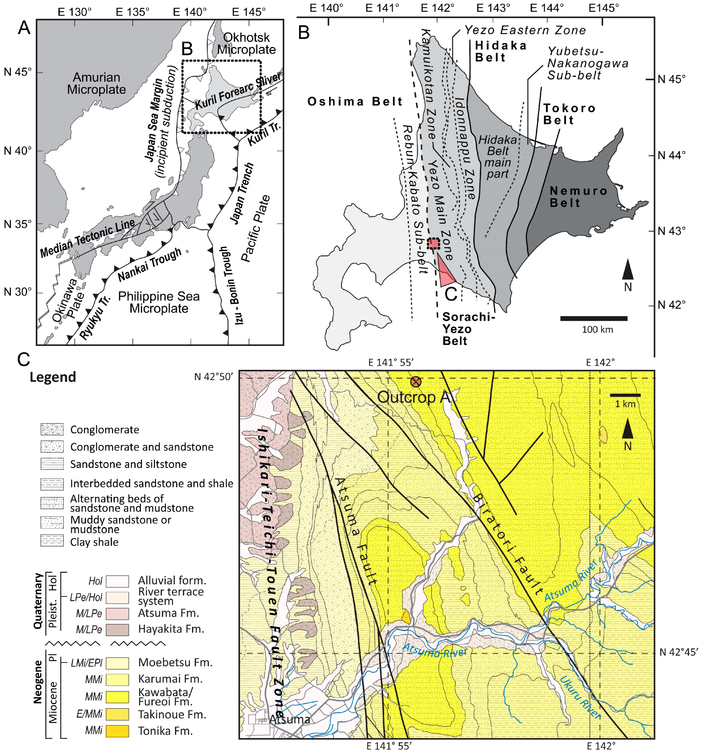
Figure 2.
Regular appearance of Kawabata Fm. appearing in the neighborhood of the studied outcrop (A), with a field image of the layers (B). The bedding plane consisting of polygonal structures (mud cracks or desiccation cracks) is exposed by the scarp of a landslide (C). Potential polygonal surface (PS1, PS2, and PS3) generations revealed by field study (D), and the polygonal unit taken for further laboratory analysis (E). The abbreviations are: P0 – recent soil, P1 – (late) Pleistocene (Pleist) cambisol-like paleosol, S1 – Pleistocene (Pleist) / Holocene (Hol) sediment unit, BA – transitional soil horizon, Bw – weathered subsoil layer, and Bw-C – transition horizon between Bw and C. The red and white sections in the scale indicate 10 cm (Figure 2C,D). The abbreviation MMi stands for Middle Miocene.
Figure 2.
Regular appearance of Kawabata Fm. appearing in the neighborhood of the studied outcrop (A), with a field image of the layers (B). The bedding plane consisting of polygonal structures (mud cracks or desiccation cracks) is exposed by the scarp of a landslide (C). Potential polygonal surface (PS1, PS2, and PS3) generations revealed by field study (D), and the polygonal unit taken for further laboratory analysis (E). The abbreviations are: P0 – recent soil, P1 – (late) Pleistocene (Pleist) cambisol-like paleosol, S1 – Pleistocene (Pleist) / Holocene (Hol) sediment unit, BA – transitional soil horizon, Bw – weathered subsoil layer, and Bw-C – transition horizon between Bw and C. The red and white sections in the scale indicate 10 cm (Figure 2C,D). The abbreviation MMi stands for Middle Miocene.
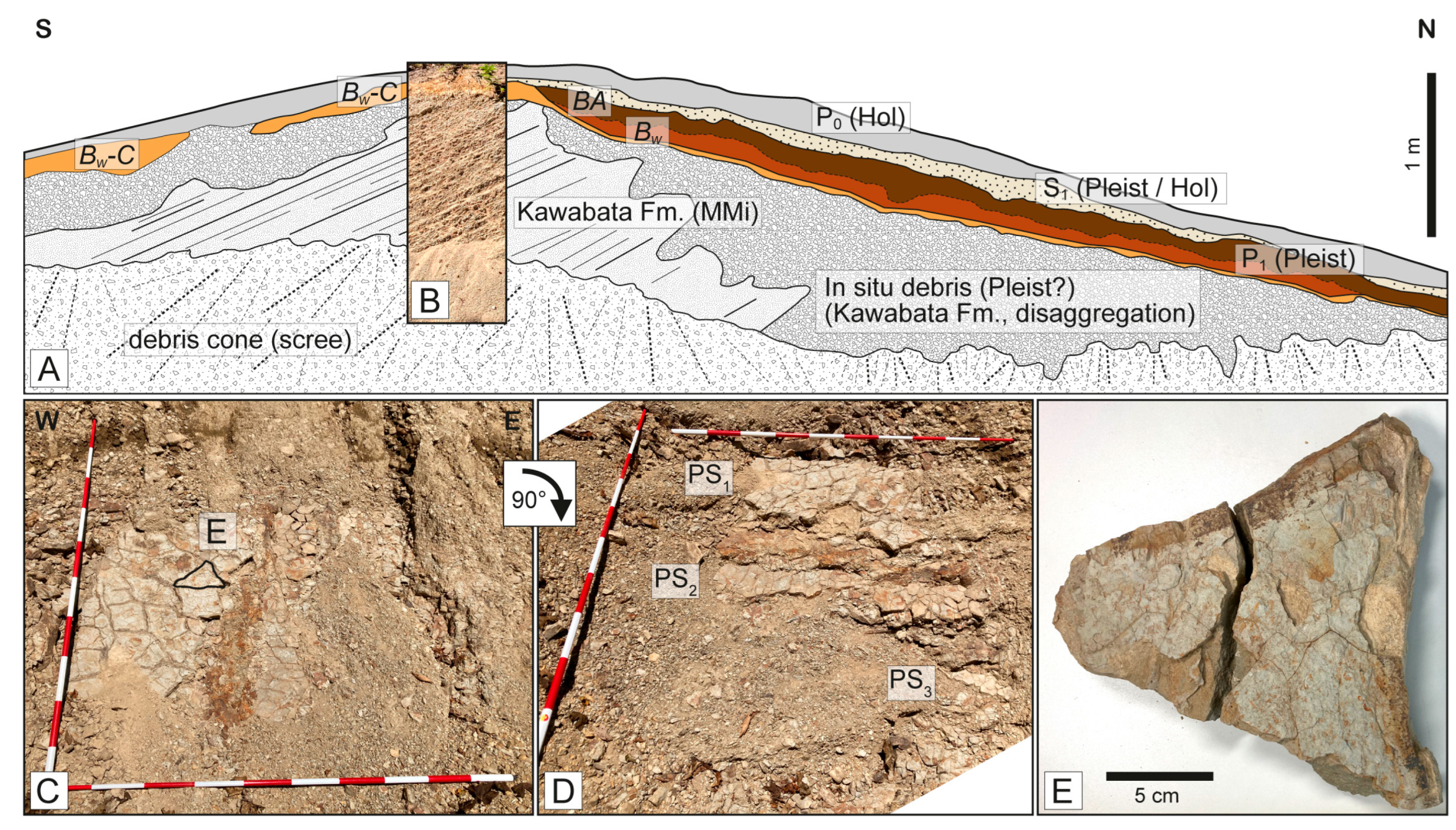
Figure 3.
Vertically oriented thin sections prepared for binocular microscopy and SEM analysis (from A to D), and a higher resolution binocular microscopic image of the thin section introduced in Figure 3D (E). Please note that during the preliminary studies, the thin sections were not polished to the standard 30 µm, because SEM analysis does not require such a thickness.
Figure 3.
Vertically oriented thin sections prepared for binocular microscopy and SEM analysis (from A to D), and a higher resolution binocular microscopic image of the thin section introduced in Figure 3D (E). Please note that during the preliminary studies, the thin sections were not polished to the standard 30 µm, because SEM analysis does not require such a thickness.
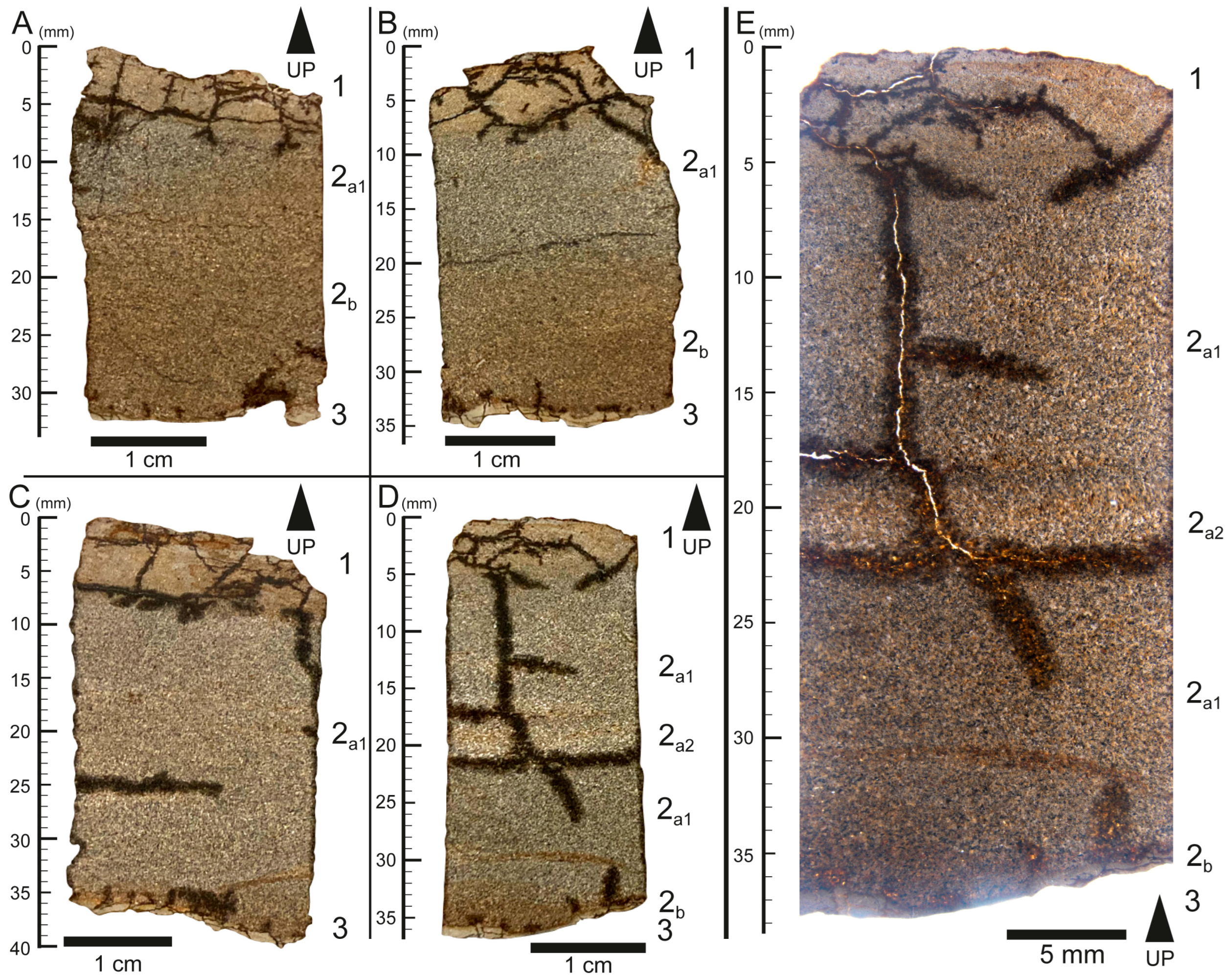
Figure 4.
Micrograph of various features observed in the pilot sample of the preliminary SEM study. The abbreviations are: ab – albite, ani – anilite, bt – biotite, fsp – feldspar, goe – goethite (limonite), pl – plagioclase, and qtz – quartz. .
Figure 4.
Micrograph of various features observed in the pilot sample of the preliminary SEM study. The abbreviations are: ab – albite, ani – anilite, bt – biotite, fsp – feldspar, goe – goethite (limonite), pl – plagioclase, and qtz – quartz. .
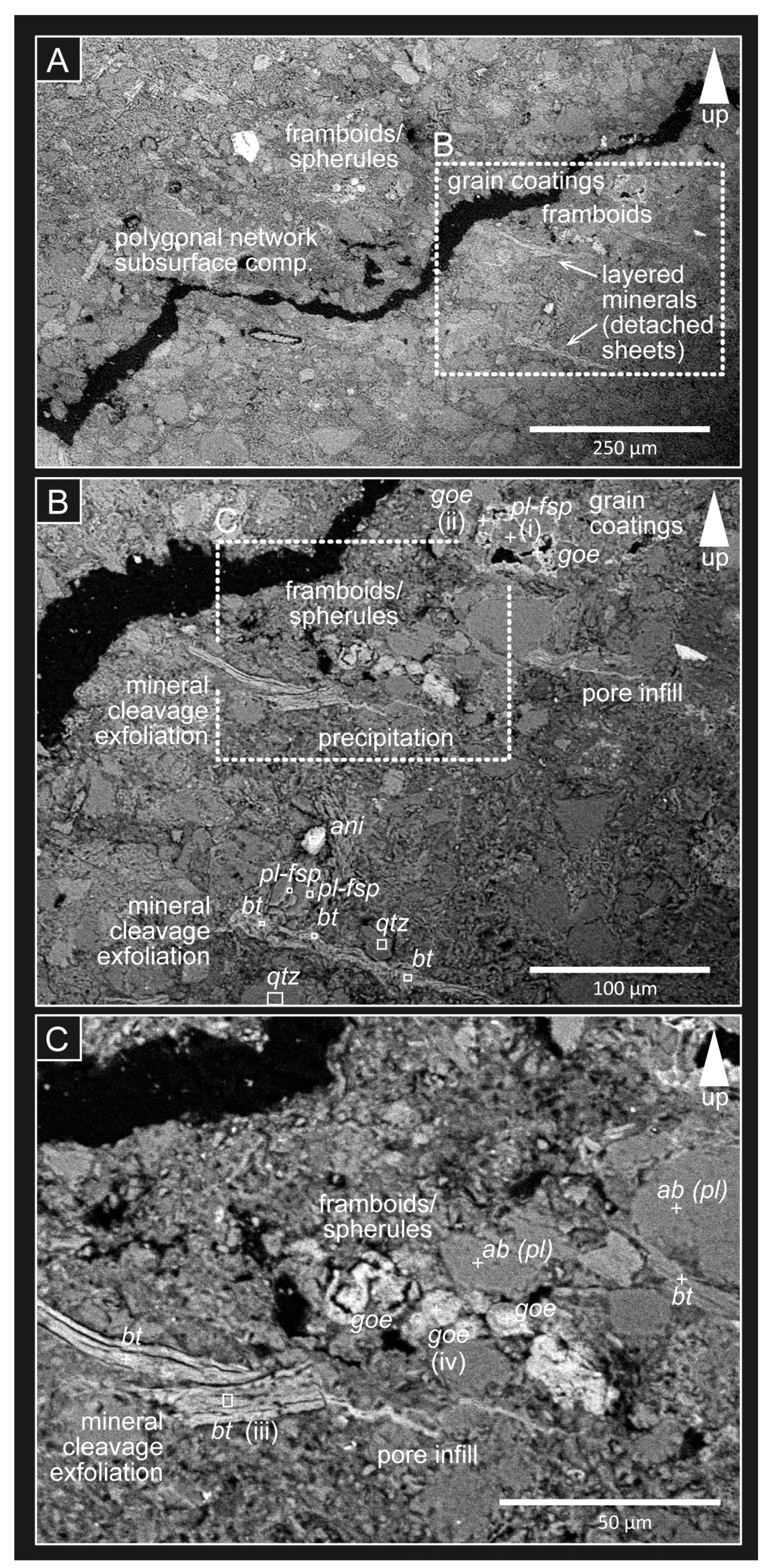
Figure 5.
EDS spectra of some of the observed minerals (mineral association) in the micrograph marked by i, ii, iii, and iv, and introduced in Figure 4: plagioclase feldspar grains (A), goethite (limonite) grain coating with plagioclase (B), biotite grain (C), and goethite (limonite) pseudomorphs of pyrite framboids/goethite spherules. The abbreviations are: bt – biotite, fsp – feldspar, goe – goethite (limonite), and pl – plagioclase.
Figure 5.
EDS spectra of some of the observed minerals (mineral association) in the micrograph marked by i, ii, iii, and iv, and introduced in Figure 4: plagioclase feldspar grains (A), goethite (limonite) grain coating with plagioclase (B), biotite grain (C), and goethite (limonite) pseudomorphs of pyrite framboids/goethite spherules. The abbreviations are: bt – biotite, fsp – feldspar, goe – goethite (limonite), and pl – plagioclase.
Disclaimer/Publisher’s Note: The statements, opinions and data contained in all publications are solely those of the individual author(s) and contributor(s) and not of MDPI and/or the editor(s). MDPI and/or the editor(s) disclaim responsibility for any injury to people or property resulting from any ideas, methods, instructions or products referred to in the content. |
© 2026 by the authors. Licensee MDPI, Basel, Switzerland. This article is an open access article distributed under the terms and conditions of the Creative Commons Attribution (CC BY) license (http://creativecommons.org/licenses/by/4.0/).
Copyright: This open access article is published under a Creative Commons CC BY 4.0 license, which permit the free download, distribution, and reuse, provided that the author and preprint are cited in any reuse.