
Submitted:
16 June 2026
Posted:
17 June 2026
You are already at the latest version
Abstract
This study evaluated the biomechanical effects of abutment types, superstructure materials, prosthetic designs, and loading conditions in the implant-supported rehabilitation of three consecutive missing teeth in the mandibular posterior region using three-dimensional finite element analysis (FEA). Twenty FEA models were constructed, simulating two-implant (pontic, mesial, and distal cantilever) and three-implant (splinted and unsplinted) configurations using Multi-unit and Ti-base abutments, with monolithic zirconia and zirconia-supported feldspathic porcelain superstructures. Functional and parafunctional (bruxism) vertical and oblique loads were applied to analyze von Mises stresses in the components and principal stresses in the bone and superstructures. The results indicated that two-implant models generated higher stresses than three-implant models, and unsplinted/cantilever designs produced higher stresses than splinted/pontic designs. Ti-base abutments resulted in greater stress accumulation in the connection complex compared to Multi-unit systems. Under vertical and oblique parafunctional forces, stress on the abutments in distal cantilever models—and in unsplinted Ti-base designs under oblique parafunctional forces—exceeded the titanium yield strength (890 MPa). To optimize biomechanical stability, three-implant supported, splinted designs with Multi-unit abutments should be preferred. Avoiding distal cantilevers and unsplinted designs is critical for long-term clinical success in patients with bruxism to prevent plastic deformation.
Keywords:
finite element analysis
; biomechanics
; bruxism
; zirconia
; multi-unit
; Ti-base
; cantilever
1. Introduction
Implant-supported fixed restorations have become the standard of care in contemporary dentistry, offering a highly predictable and reliable treatment option for the rehabilitation of missing teeth [1]. However, the long-term clinical success of implant therapy relies not only on achieving surgical osseointegration but also on the biomechanical balance that dictates how occlusal loads are transmitted to the implant, prosthetic components, and surrounding bone. The posterior mandible represents one of the most challenging areas for biomechanical stability due to its high masticatory forces, the prevalence of oblique loading, proximity to the inferior alveolar nerve, and anatomical limitations regarding bone volume [2,3]. Unlike natural teeth, dental implants lack a periodontal ligament; consequently, occlusal forces are transmitted directly to the implant, abutment, and surrounding bone. This lack of shock absorption leads to crestal stress concentrations, which are recognized as primary triggers for marginal bone loss and mechanical failure [4,5].
Clinical decision-making for the rehabilitation of consecutive tooth loss in this region necessitates a multi-parametric evaluation, including implant number, splinting strategy, cantilever presence, abutment design, and restorative material selection. While increasing the number of implants may facilitate a broader distribution of occlusal forces, non-ideal positioning and distal cantilever extensions create a leverage effect, potentially leading to stress accumulation in the implant–abutment complex and peri-implant bone [6,7]. The degree of splinting further influences this stress distribution; splinted superstructures homogenize load distribution, whereas unsplinted restorations are often preferred for passive fit and hygienic access [8]. Furthermore, connection stability is directly linked to the chosen abutment system. Multi-unit abutments, which facilitate a passive fit at the tissue level, are often compared with hybrid Ti-base systems that synthesize the mechanical strength of titanium with the esthetic advantages of CAD/CAM materials [9]. Variations in the elastic modulus of the crown materials used on these systems (e.g., monolithic zirconia vs. layered porcelain) fundamentally alter how stress is damped and transmitted to the bone [10].
These prosthetic considerations become exceptionally critical in the presence of bruxism, defined as repetitive jaw-muscle activity [11]. Increased occlusal forces impose additional loads on the implant–abutment interface, compromise screw stability, and challenge restorative material strength. Three-dimensional finite element analysis (FEA) serves as an indispensable research tool for investigating these complex stress distributions that cannot be directly assessed clinically, guiding decision-making by elucidating biomechanical trends under risk-prone loading conditions [12].
The primary aim of this research was to compare the biomechanical performance of different treatment configurations—including two- versus three-implant configurations, cantilever presence, Multi-unit versus Ti-base abutments, splinting strategies, and superstructure materials—under both physiological loads and parafunctional forces simulating bruxism using FEA. The null hypothesis tested was that variations in implant number, configuration, abutment type, splinting strategy, and superstructure material would not significantly influence stress distribution or damage risk within the peri-implant bone complex and prosthetic components.
2. Materials and Methods
The study protocol was approved by the local Ethics Committee (Approval No: 2025/724, Date: 25.12.2025). The mandibular bone model used in this study was generated from computed tomography (CT) slices (0.33 mm thickness) obtained from the Visible Human Project database. The DICOM images were segmented using 3D Slicer software. An inward offset of 2 mm was applied to the anatomical model using Blender software to create the cortical and trabecular bone layers. For the purpose of biomechanical standardization, the mandibular canal was eliminated from the model [13].
Bone-level dental implants measuring 4.1 × 10 mm (Straumann BLT, Switzerland), alongside Multi-unit and Ti-base abutments with a 1 mm gingival height, and prosthetic superstructures, were utilized for placement in the posterior mandible. The original industrial CAD data of the components were converted into solid models using SolidWorks software (Dassault Systèmes, USA) and integrated with the occlusal crown and bone anatomy. Reverse engineering processes were completed using Rhinoceros 3D software. Preparation of the models for FEA—including mesh generation with the assumption of 100% osseointegration and interfacial adaptations—was performed using ALTAIR Hypermesh, while stress analysis solutions were executed using ALTAIR Optistruct software (ALTAIR, USA).
The missing teeth in the posterior mandibular region (teeth 44, 45, and 46) were modeled referencing Wheeler's Dental Anatomy atlas [14]. Based on the implant positions, splinted, unsplinted, pontic, and cantilevered superstructure designs were generated. To ensure standardization, the total thicknesses of the monolithic zirconia restorations and the zirconia-supported feldspathic porcelain restorations were kept equal. To simulate clinical conditions more realistically, a 50-µm-thick dual-cure resin cement layer was defined between the abutment and the superstructure [15]. The grouping and visual representations of the 20 different models tested in this study are provided in Table 1 and Figure 1.
All structures used in the analysis were assumed to be linear elastic, homogeneous, and isotropic. The elastic modulus and Poisson's ratio values for the materials were obtained from the literature and defined in the system (Table 2).
To simulate physiological and parafunctional (bruxism) masticatory forces, four different static loading scenarios were defined for each of the 20 models, resulting in a total of 80 analyses. To prevent stress singularity, the forces were applied by distributing them across the surrounding nodes in the loading areas. The loading scenarios and force distributions used in the biomechanical analyses are summarized in Table 3 and Figure 2.
3. Results
Overall evaluation of the models revealed that parafunctional loading conditions consistently generated higher stress values compared to functional loading. This increasing trend was observed under both vertical and oblique loading scenarios. The highest stress values were predominantly localized within the abutment component, whereas the lowest values were recorded in the trabecular bone. Stress accumulations in the cortical bone were significantly higher than those in the trabecular bone, with stress concentrations primarily localized at the implant cervix and the surrounding peri-implant cortical bone regions.
Under vertical functional loading, the maximum stress values were recorded as 222.886 MPa for the implant (Model 17), 468.588 MPa for the abutment (Model 15), and 135.678 MPa for the retaining screw (Model 20). When subjected to parafunctional vertical loading, the peak stress values for these corresponding components increased to 557.215 MPa, 1171.470 MPa, and 339.196 MPa, respectively.
Under oblique functional loading conditions, the maximum stress values were 234.320 MPa for the implant (Model 17), 519.953 MPa for the abutment (Model 20), and 148.676 MPa for the screw (Model 20). Under parafunctional oblique loading scenarios, these maximum stress values escalated to 780.285 MPa for the implant (Model 17), 1731.442 MPa for the abutment (Model 20), and 495.090 MPa for the retaining screw (Model 20).
Regarding the biological and restorative structures under vertical functional loading, the maximum stress values were recorded as 99.288 MPa for the cortical bone (Model 07), 5.000 MPa for the trabecular bone (Model 07), and 412.506 MPa for the superstructure (Model 02). Under vertical parafunctional conditions, the peak stresses reached 248.219 MPa in the cortical bone (Model 07), 12.508 MPa in the trabecular bone (Model 17), and 1039.507 MPa in the superstructure (Model 12).
Under oblique functional loading, the maximum recorded stress values were 62.685 MPa for the cortical bone (Model 17), 2.739 MPa for the trabecular bone (Models 15 and 20), and 212.106 MPa for the superstructure (Model 12). Finally, under oblique parafunctional loading conditions, the highest stress concentrations were determined as 208.223 MPa for the cortical bone (Model 07), 9.121 MPa for the trabecular bone (Model 15), and 706.314 MPa for the superstructure (Model 12). These findings are summarized in Table 4.
The number of implants and the prosthetic design were observed to have a pronounced effect on stress distribution. Models supported by three implants generally yielded lower or more balanced stress distributions across the implant, abutment, screw, and bone tissues compared to two-implant supported models. This trend was particularly evident in splinted, three-implant supported designs.
When examining the mechanical effect of the presence and direction of a cantilever on the system, the highest stress values were observed to accumulate at the implant region adjacent to the cantilever. Comparing the restoration designs, the stress concentration ranking across all components (implant, abutment, screw, and bone) generally followed the order of Distal Cantilever > Mesial Cantilever > Pontic. Specifically, models featuring a distal cantilever design (Models 02, 07, 12, 17) exhibited significantly higher stress levels compared to mesial cantilever models. As the most critical finding of the study, it was determined that under parafunctional loads, the maximum stress values on the abutment in models with distal cantilever extensions exceeded 890 MPa, which is the yield strength limit of titanium.
Evaluating splinted and unsplinted restoration designs revealed that splinted models (Models 04, 09, 14, 19) distributed stresses more evenly among the implants in the system, whereas in unsplinted models, stresses reached higher localized levels at specific connection components.
When comparing abutment systems under all loading conditions applied in vertical and oblique directions, it was found that models utilizing Ti-base abutments were subjected to much higher stress levels in the implant, abutment, and screw components compared to models utilizing Multi-unit abutments. In Ti-base systems, stress was observed to be localized particularly at the internal connection geometry of the implant and the abutment neck. Under oblique parafunctional (bruxism) loading, it was recorded that the maximum von Mises stresses on the abutment in unsplinted Ti-base designed models also exceeded the 890 MPa yield strength of titanium (creating a risk of plastic deformation). Conversely, Multi-unit systems managed to keep the components below this critical threshold by distributing the load over a broader surface.
Regarding the superstructure material, the stress values generated in the superstructure component were found to be lower in models using zirconia-supported feldspathic porcelain compared to monolithic zirconia models. However, the impact of material variation on the stresses in the implant, abutment, screw, cortical bone, and trabecular bone remained limited. Consequently, while the effect of the superstructure material was more pronounced on the stress behavior within the restoration itself, the abutment system, cantilever presence, splinting status, and loading direction were observed to be more dominant regarding the stress on the implant and connection components.
Analyzing stress transmission in the bone tissues, it was determined that the principal stress values generated in the cortical bone were considerably higher than the stress levels in the trabecular bone across all models and loading scenarios. Stresses generally reached their maximum in the cortical bone at the cervical (neck) region of the implant, while rapidly attenuating in the trabecular bone and toward the implant apex.
Comparing physiological and parafunctional (bruxism) loading scenarios, it was found that parafunctional forces exhibited a similar distribution pattern (profile) to functional loads across all models but elevated stress levels to much more dramatic and destructive values. In particular, oblique parafunctional forces, compared to vertical forces, were observed to create a much more adverse condition in the biomechanical system by increasing bending moments, leading to high stress foci in the implant neck region, abutment interface, and cortical bone. Under oblique parafunctional loading, the highest abutment and screw stresses were recorded in Model 20, which incorporated a Ti-base, zirconia-supported feldspathic porcelain, and an unsplinted three-implant design. This demonstrates that the direction of loading alters the biomechanical behavior of the system independently of the force magnitude alone.
In all design variations (pontic, cantilever, splinted, unsplinted), the highest stress values were consistently measured in the components placed in the first molar region, where the occlusal force was applied most severely (Figure 3, Figure 4, Figure 5, Figure 6, Figure 7, Figure 8, Figure 9, Figure 10, Figure 11, Figure 12, Figure 13 and Figure 14).
4. Discussion
In this study, the biomechanical behaviors of implant number (2 and 3 implants), prosthetic design (pontic, cantilever, splinted), abutment system (Multi-unit and Ti-base), and restorative material (monolithic zirconia and porcelain-veneered zirconia) under physiological and parafunctional (bruxism) loading in the rehabilitation of multiple missing teeth in the posterior mandible were investigated using finite element analysis (FEA). Based on the findings obtained, the null hypothesis was rejected.
One of the primary strategies for reducing mechanical stress in multi-unit posterior restorations is increasing the number of supporting implants. In the present study, increasing the number of implants from two to three significantly reduced the stress values in all components (cortical/trabecular bone, implant body, abutment, screw, and superstructure) under both axial and oblique loading conditions. This finding is consistent with previous literature reporting that an increase in the number of supporting implants expands the load-bearing area and decreases the amount of force transmitted per unit [20,21]. However, an increase in the number of implants should not be considered an absolute clinical advantage on its own. Indeed, a long-term clinical study by Ravidà et al. [22] demonstrated that, contrary to laboratory data, two-implant-supported bridge designs may have higher survival rates compared to three-implant restorations. In this context, the biomechanical advantages of increasing the number of implants must be evaluated alongside clinical requirements such as hygiene maintenance and passive fit.
Furthermore, splinted designs were found to distribute stresses more homogeneously among components compared to independent (unsplinted) designs. It has been confirmed that splinting restorations, especially in scenarios of reduced bone support or excessive occlusal loading, prevents focal stress accumulations and protects the system against bending moments [23,24].
Among the prosthetic designs configured in the mandibular posterior region, the highest stress accumulations were observed in models with distal cantilevers (Models 02, 07, 12, 17). Cantilever extensions create a leverage effect in the system, reflecting stress directly onto the implant adjacent to the extension and the connection components [25,27]. The most critical picture in stress distribution was observed to progress in the order of distal cantilever > mesial cantilever > pontic design [6]. In cases where the use of a cantilever is mandatory, it has once again been proven that mesial extensions are biomechanically much safer than distal extensions due to their anatomical and occlusal advantages [7]. The most critical and striking finding of the present study was observed in parafunctional (bruxism) loading scenarios: The maximum principal stress on the abutment in models containing a distal cantilever exceeded the 890 MPa limit, which is the yield strength of titanium. This indicates that excessive forces applied to distal extensions lead to plastic (permanent) deformation in titanium components. This numerical evidence mathematically explains the high incidence of abutment fractures and screw loosening [27] associated with posterior cantilever restorations in clinical practice and strongly recommends that these designs should not be used in bruxism patients.
The retention concept and abutment geometry play a decisive role in damping occlusal forces. In this study, Ti-base systems were found to generate higher stress values in the implant, screw, and abutment components compared to Multi-unit systems. The interlocking geometry of Ti-base abutments, which integrates into the internal structure of the implant, creates a "wedge effect" under applied forces, localizing stress in a narrow area [27]. In contrast, multi-part Multi-unit systems, which elevate the restorative platform to the supragingival level, were observed to distribute forces more evenly, thereby protecting the implant and bone interface [29,30]. However, it should be considered that Ti-base systems may provide advantages in esthetic zones, and their generation of higher stress does not mean absolute clinical failure.
When evaluating the stresses within the superstructure itself, higher internal stress concentrations were detected in monolithic zirconia restorations due to their high elastic modulus. However, this biomechanical picture should not be interpreted as a clinical disadvantage. Although monolithic zirconia directly withstands applied occlusal loads within its own structure due to its rigid nature, it can tolerate these stresses without failure thanks to its superior fracture toughness. Furthermore, the single-piece monolithic structure completely eliminates veneer chipping, which is the most frequently encountered clinical complication of layered ceramic restorations [31,32]. Therefore, despite generating higher superstructure stresses in finite element analysis, monolithic zirconia should be considered one of the most clinically predictable and stable material alternatives in the rehabilitation of the posterior region, where excessive forces and parafunctional loads (bruxism) are prevalent.
One of the strongest methodological aspects of the present study is the configuration of the occlusal loading protocol to simulate physiological and parafunctional masticatory dynamics with high precision. In many FEA studies in the literature, simplified scenarios are preferred where the total applied occlusal force is distributed equally to all units of the restoration. However, clinical and biomechanical evidence demonstrates that the mandible functions as a Class III leverage system; the force increases dramatically moving posteriorly (toward the molar region), and the maximum occlusal capacity is concentrated in the first molar region [33,34,35]. To model this physiological reality, a "proportional loading" strategy was adopted in our study instead of homogeneous loading; the forces were distributed to the first molar, second premolar, and first premolar restorations at ratios of 50%, 30%, and 20%, respectively, thereby obtaining stress distribution profiles closest to clinical reality.
The parafunctional (bruxism) scenarios tested under this realistic loading strategy clearly revealed the destructive effect of not only the magnitude but also the direction of occlusal forces on the system. In the literature, bruxism is known to increase normal masticatory forces by 4 to 7 times and shift their direction from axial to oblique [36,37]. Similarly, in our study, oblique parafunctional forces (total 500 N) applied at a 30-degree angle in the buccolingual direction caused much more aggressive stress accumulations in all configurations compared to vertical functional forces (total 400 N). The most striking finding of the study was that under parafunctional oblique loading simulating bruxism conditions, the yield strength of titanium (890 MPa) was exceeded, creating a risk of permanent plastic deformation in the previously mentioned designs with distal cantilevers and in unsplinted models using Ti-base abutments. This mathematically explains the underlying causes of mechanical complications frequently encountered in bruxist individuals in clinical practice, such as screw loosening, screw fracture, and ceramic chipping [37]. This critical threshold confirms that, although bruxism is not a direct contraindication for implants, it is a major risk factor that necessitates protective restorative strategies such as abutment selection (use of Multi-unit), splinting, and the elimination of cantilevers.
When examining the transmission of forces to the implant-bone interface, it was observed that the highest stress concentrations localized in the cortical bone at the cervical region of the implant in every scenario and decreased apically. The maximum and minimum principal stress values generated in the cortical bone were significantly higher than the values in the trabecular bone. This finding is in full agreement with previous research reporting that trabecular bone, which has a low elastic modulus, shows weak resistance to applied loads, and that the majority of occlusal loads are absorbed by the crestal cortical bone [39,40]. This intense stress accumulation in the cortical bone explains the biomechanical cause of marginal bone resorption and demonstrates once again how critical the careful management of occlusal loads is for the long-term survival of the implant.
Although the data obtained from our study strongly align with the current literature, the results should be interpreted within the framework of certain methodological limitations inherent to in silico analyses. The complex kinematics of the human masticatory system and the dynamic effect of muscle forces cannot be perfectly replicated in a computational environment. The limitations of the study include the assumptions in the FEA simulations that the materials are homogeneous and linear elastic, and that the bone-implant interface is 100% osseointegrated. The findings obtained should be evaluated as a guide shedding light on the biomechanical risk profiles of different prosthetic designs, rather than as absolute clinical failure rates.
5. Conclusions
Within the limitations of this finite element stress analysis study, the following clinical and biomechanical conclusions were drawn:
- Increasing the number of implants from two to three and opting for splinted designs instead of independent crowns significantly reduced stresses on the entire prosthetic system and bone tissue, providing a more balanced load distribution.
- Among the prosthetic designs, the highest stress accumulations were observed in distal cantilever, mesial cantilever, and pontic designs, respectively. Pontic designs should be preferred whenever possible; in obligatory cases, the biomechanically safer mesial cantilever should be applied.
- Ti-base abutment systems transmitted occlusal loads more locally, causing significantly higher stresses in the implant and screw complex compared to Multi-unit systems. Multi-unit systems exhibited a biomechanically more protective profile, particularly in multi-unit posterior restorations.
- Under vertical and oblique parafunctional (bruxism) loading in models with distal cantilever extensions, and under oblique parafunctional loading in unsplinted designs using Ti-base abutments, abutment stresses exceeded the yield strength of titanium (890 MPa), reaching the limit of permanent deformation. These specific combinations must be avoided in the posterior restorations of bruxist individuals.
- The selection of the restorative superstructure material (monolithic or layered zirconia) has no significant biomechanical impact on the stress profile transmitted to the implant components and surrounding bone tissues (cortical and trabecular). It was determined that the mechanical stresses generated by occlusal forces are predominantly borne by the crestal cortical bone rather than the trabecular bone. In this context, the maintenance of long-term peri-implant tissue health depends on the optimization of macroscopic prosthetic parameters, such as splinting, appropriate abutment selection, and the avoidance of cantilever extensions, rather than material modifications.
Author Contributions
Conceptualization, M.A. and [C.A.]; methodology, M.A.; software, M.A.; validation, M.A. and [C.A.]; formal analysis, M.A.; investigation, M.A.; resources, [C.A.]; data curation, M.A.; writing—original draft preparation, M.A.; writing—review and editing, [C.A.]; visualization, M.A.; supervision, [C.A.]; project administration, [C.A.]; funding acquisition, [C.A.]. All authors have read and agreed to the published version of the manuscript.
Funding
This research received no external funding.
Institutional Review Board Statement
The study protocol was approved by the Local Ethics Committee of Necmettin Erbakan University (Approval No: 2025/724, Date: 25.12.2025).
Informed Consent Statement
Patient consent was waived due to the retrospective use of completely anonymized cone-beam computed tomography (CBCT) data solely for the purpose of three-dimensional anatomical modeling in finite element analysis, in accordance with the ethical approval.
Data Availability Statement
The data presented in this study are available on request from the corresponding author.
Acknowledgments
The authors would like to acknowledge Tinus Technologies for their valuable technical support and cooperation during the three-dimensional modeling and finite element analysis processes of this study.
Conflicts of Interest
The authors declare no conflicts of interest. The funders had no role in the design of the study; in the collection, analyses, or interpretation of data; in the writing of the manuscript; or in the decision to publish the results.
Abbreviations
The following abbreviations are used in this manuscript:
| FEA | Finite Element Analysis |
| CBCT | Cone-Beam Computed Tomography |
| MPa | Megapascal |
| Ti | Titanium |
| Ti-base | Titanium Base |
| MU | Multi-unit |
| MZ | Monolithic Zirconia |
| Zr-P | Porcelain-veneered Zirconia |
| Pmax | Maximum Principal Stress |
| N | Newton |
References
- Buser, D.; Sennerby, L.; De Bruyn, H. Modern implant dentistry based on osseointegration: 50 years of progress, current trends and open questions. Periodontol. 2000 2017, 73, 7–21. [Google Scholar]
- Ataman-Duruel, E.T.; Beycioğlu, Z.; Yılmaz, D.; Goyushov, S.; Çimen, T.; Duruel, O.; Yılmaz, H.G.; Tözüm, T.F. Evaluation of cortical thicknesses and bone density values of mandibular canal borders and coronal site of alveolar crest. J. Oral Maxillofac. Res. 2023, 14, e4. [Google Scholar] [CrossRef] [PubMed]
- Rajkovic Pavlovic, Z.; Stepovic, M.; Bubalo, M.; Zivanovic Macuzic, I.; Vulovic, M.; Folic, N.; Milosavljevic, J.; Opancina, V.; Stojadinovic, D. Anatomic variations important for dental implantation in the mandible—A systematic review. Diagnostics 2025, 15, 155. [Google Scholar] [CrossRef] [PubMed]
- Kim, Y.; Oh, T.-J.; Misch, C.E.; Wang, H.-L. Occlusal considerations in implant therapy: Clinical guidelines with biomechanical rationale. Clin. Oral Implant. Res. 2005, 16, 26–35. [Google Scholar]
- Zupancic Cepic, L.; Frank, M.; Reisinger, A.; Pahr, D.; Zechner, W.; Schedle, A. Biomechanical finite element analysis of short-implant-supported, 3-unit, fixed CAD/CAM prostheses in the posterior mandible. Int. J. Implant Dent. 2022, 8, 8. [Google Scholar] [CrossRef] [PubMed]
- Aboelfadl, A.; Keilig, L.; Ebeid, K.; Ahmed, M.A.M.; Nouh, I.; Refaie, A.; Bourauel, C. Biomechanical behavior of implant retained prostheses in the posterior maxilla using different materials: A finite element study. BMC Oral Health 2024, 24, 455. [Google Scholar] [CrossRef] [PubMed]
- Yüksel Baysal, A.; Hayran, Y. Biomechanical evaluation of implant-supported three-unit bridge designs and retention types in the atrophic posterior maxilla using finite element analysis. Appl. Sci. 2025, 15, 11793. [Google Scholar] [CrossRef]
- Lemos, C.A.A.; Verri, F.R.; Santiago Júnior, J.F.; de Souza Batista, V.E.; Kemmoku, D.T.; Noritomi, P.Y.; Pellizzer, E.P. Splinted and nonsplinted crowns with different implant lengths in the posterior maxilla by three-dimensional finite element analysis. J. Healthc. Eng. 2018, 2018, 3163096. [Google Scholar] [CrossRef] [PubMed]
- Chantler, J.G.M.; Evans, C.D.J.; Zitzmann, N.U.; Derksen, W. Clinical performance of single implant prostheses restored using titanium base abutments: A systematic review and meta-analysis. Clin. Oral Implant. Res. 2023, 34 (Suppl. 26), 64–85. [Google Scholar] [CrossRef] [PubMed]
- Dayan, S.C.; Geckili, O. The influence of framework material on stress distribution in maxillary complete-arch fixed prostheses supported by four dental implants: A three-dimensional finite element analysis. Comput. Methods Biomech. Biomed. Engin. 2021, 24, 1606–1617. [Google Scholar] [CrossRef] [PubMed]
- Lobbezoo, F.; Ahlberg, J.; Raphael, K.G.; Wetselaar, P.; Glaros, A.G.; Kato, T.; Santiago, V.; Winocur, E.; De Laat, A.; De Leeuw, R.; Koyano, K.; Lavigne, G.J.; Svensson, P.; Manfredini, D. International consensus on the assessment of bruxism: Report of a work in progress. J. Oral Rehabil. 2018, 45, 837–844. [Google Scholar] [CrossRef] [PubMed]
- Falcinelli, C.; Valente, F.; Vasta, M.; Traini, T. Finite element analysis in implant dentistry: State of the art and future directions. Dent. Mater. 2023, 39, 539–556. [Google Scholar] [CrossRef] [PubMed]
- Kul, E.; Korkmaz, İ.H. Effect of different design of abutment and implant on stress distribution in 2 implants and peripheral bone: A finite element analysis study. J. Prosthet. Dent. 2021, 126, 664.e1–664.e9. [Google Scholar] [CrossRef] [PubMed]
- Nelson, S.J.; Ash, M.M., Jr. Wheeler’s Dental Anatomy, Physiology, and Occlusion, 9th ed.; Saunders Elsevier: St. Louis, MO, USA, 2010; pp. 189–199. [Google Scholar]
- Lee, H.; Park, S.; Noh, G. Biomechanical analysis of 4 types of short dental implants in a resorbed mandible. J. Prosthet. Dent. 2019, 121, 659–670. [Google Scholar] [CrossRef] [PubMed]
- Sannino, G.; Gloria, F.; Ottria, L.; Barlattani, A. Influence of finish line in the distribution of stress through an all ceramic implant-supported crown: A 3D finite element analysis. Oral Implantol. 2009, 2, 14–27. [Google Scholar]
- Chen, X.Y.; Zhang, C.Y.; Nie, E.M.; Zhang, M.C. Treatment planning of three missing mandibular posterior teeth with implants: A three-dimensional finite element analysis. Implant Dent. 2012, 21, 340–343. [Google Scholar] [CrossRef] [PubMed]
- Mozayek, R.S.; Allaf, M.; Dayoub, S. Porcelain sectional veneers, an ultra-conservative technique for diastema closure (three-dimensional finite element stress analysis). Dent. Med. Probl. 2019, 56, 179–183. [Google Scholar] [CrossRef] [PubMed]
- Kaleli, N.; Sarac, D.; Külünk, Ş.; Öztürk, Ö. Effect of different restorative crown and customized abutment materials on stress distribution in single implants and peripheral bone: A three-dimensional finite element analysis study. J. Prosthet. Dent. 2018, 119, 437–445. [Google Scholar] [CrossRef] [PubMed]
- Park, J.-H.; Kim, S.-H.; Han, J.-S.; Lee, J.-B.; Yang, J.-H. Effect of number of implants and cantilever design on stress distribution in three-unit fixed partial dentures: A three-dimensional finite element analysis. J. Korean Acad. Prosthodont. 2008, 46, 290–298. [Google Scholar]
- Toniollo, M.B.; Vieira, L.J.P.; Sá, M.D.S.; Macedo, A.P.; Melo, J.P., Jr.; Terada, A.S.S.D. Stress distribution of three-unit fixed partial prostheses (conventional and pontic) supported by three or two implants: 3D finite element analysis of ductile materials. Comput. Methods Biomech. Biomed. Engin. 2019, 22, 706–712. [Google Scholar] [CrossRef] [PubMed]
- Ravidà, A.; Tattan, M.; Askar, H.; Barootchi, S.; Tavelli, L.; Wang, H.L. Comparison of three different types of implant-supported fixed dental prostheses: A long-term retrospective study of clinical outcomes and cost-effectiveness. Clin. Oral Implant. Res. 2019, 30, 295–305. [Google Scholar] [CrossRef] [PubMed]
- Guichet, J.G.; Yoshinobu, D.; Caputo, A.A. Effect of splinting and interproximal contact tightness on load transfer by implant restorations. J. Prosthet. Dent. 2002, 87, 528–535. [Google Scholar] [CrossRef] [PubMed]
- Güngör Erdoğan, H.; Keleş, M.; Yılmaz, B. Comparison of stress distribution around splinted and nonsplinted implants with different crown height space in posterior mandible: A finite element analysis study. J. Prosthodont. 2024. [Google Scholar] [CrossRef] [PubMed]
- Sertgöz, A.; Güvener, S. Finite element analysis of the effect of cantilever and implant length on stress distribution in an implant-supported fixed prosthesis. J. Prosthet. Dent. 1996, 76, 165–169. [Google Scholar] [CrossRef] [PubMed]
- Kunavisarut, C.; Lang, L.A.; Stoner, B.R.; Felton, D.A. Finite element analysis on dental implant-supported prostheses without passive fit. J. Prosthodont. 2002, 11, 30–40. [Google Scholar] [CrossRef] [PubMed]
- Kondo, Y.; Sakai, K.; Minakuchi, H.; Horimai, T.; Kuboki, T. JSOI Clinical Guideline Working Group collaborators. Implant-supported fixed prostheses with cantilever: A systematic review and meta-analysis. Int. J. Implant Dent. 2024, 10, 61. [Google Scholar] [CrossRef] [PubMed]
- Poovarodom, P.; Moura, G.F.; Rizzante, F.A.P.; Rungsiyakull, C.; Suriyawanakul, J.; Rungsiyakull, P. Mechanical behavior of hybrid custom implant abutments with various crown materials: A 3D finite element analysis. BMC Oral Health 2025, 25, 1106. [Google Scholar] [CrossRef] [PubMed]
- Aalaei, S.; Rajabi Naraki, Z.; Nematollahi, F.; Beyabanaki, E.; Shahrokhi Rad, A. Stress distribution pattern of screw-retained restorations with segmented vs. non-segmented abutments: A finite element analysis. J. Dent. Res. Dent. Clin. Dent. Prospect. 2017, 11, 149–155. [Google Scholar] [CrossRef] [PubMed]
- Karayel, A.B.; Canay, Ş. Ti-base ve multi-unit dayanaklar: Vida tutuculu restorasyonlar için karşılaştırmalı bir bakış. Acta Odontol. Turc. 2026, 43, 49–59. [Google Scholar] [CrossRef]
- Pjetursson, B.E.; Sailer, I.; Latyshev, A.; Rabel, K.; Kohal, R.J.; Karasan, D. A systematic review and meta-analysis evaluating the survival, the failure, and the complication rates of veneered and monolithic all-ceramic implant-supported single crowns. Clin. Oral Implant. Res. 2021, 32 (Suppl. 21), 254–288. [Google Scholar] [CrossRef] [PubMed]
- Schley, J.S.; Heussen, N.; Reich, S.; Fischer, J.; Haselhuhn, K.; Wolfart, S. Survival probability of zirconia-based fixed dental prostheses up to 5 yr: A systematic review of the literature. Eur. J. Oral Sci. 2010, 118, 443–450. [Google Scholar] [CrossRef] [PubMed]
- Miyaura, K.; Matsuka, Y.; Morita, M.; Yamashita, A.; Watanabe, T. Comparison of biting forces in different age and sex groups: A study of biting efficiency with mobile and non-mobile teeth. J. Oral Rehabil. 1999, 26, 223–227. [Google Scholar] [CrossRef] [PubMed]
- Kerstein, R.B.; Radke, J. Masseter and temporalis excursive hyperactivity decreased by measured anterior guidance development. Cranio 2012, 30, 243–254. [Google Scholar] [CrossRef] [PubMed]
- Sai, K.L.; Sasanka, K.; Faiz, N.; Keskar, V.; Sinha, D. A T-Scan analysis of bite force distribution in natural dentition: A prospective study. Indian J. Dent. Res. 2025, 36, 161–164. [Google Scholar] [CrossRef] [PubMed]
- Misch, C.E. Contemporary Implant Dentistry, 4th ed.; Elsevier: St. Louis, MO, USA, 2015. [Google Scholar]
- Torcato, L.B.; Pellizzer, E.P.; Verri, F.R.; Falcón-Antenucci, R.M.; Santiago Júnior, J.F.; Almeida, D.A.F. Influence of parafunctional loading and prosthetic connection on stress distribution: A 3D finite element analysis. J. Prosthet. Dent. 2015, 114. [Google Scholar] [CrossRef] [PubMed]
- Chrcanovic, B.R.; Kisch, J.; Larsson, C. Retrospective evaluation of implant-supported full-arch fixed dental prostheses after a mean follow-up of 10 years. Clin. Oral Implant. Res. 2020, 31, 634–645. [Google Scholar] [CrossRef] [PubMed]
- Duyck, J.; Naert, I.; Rønold, H.J.; Ellingsen, J.E.; van Oosterwyck, H.; Vander Sloten, J. The influence of static and dynamic loading on marginal bone reactions around osseointegrated implants: An animal experimental study. Clin. Oral Implant. Res. 2001, 12, 207–218. [Google Scholar] [CrossRef] [PubMed]
- İplikçioğlu, H.; Akça, K. Comparative evaluation of the effect of diameter, length and number of implants supporting three-unit fixed partial prostheses on stress distribution in the bone. J. Dent. 2002, 30, 41–46. [Google Scholar] [CrossRef] [PubMed]
Figure 1.
Images of all study models.
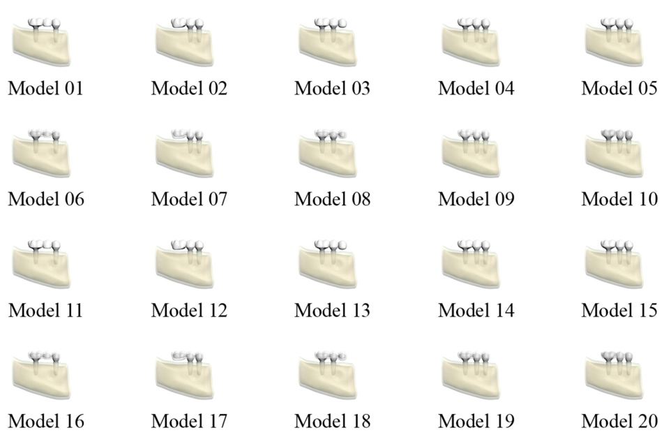
Figure 2.
Schematic illustration of the vertical (left) and oblique (right) static load applications on the prosthetic restorations.
Figure 2.
Schematic illustration of the vertical (left) and oblique (right) static load applications on the prosthetic restorations.
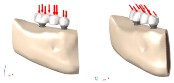
Figure 3.
Von Mises stress values in the implant, abutment, and screw of Models (01-20) under vertical functional loading.
Figure 3.
Von Mises stress values in the implant, abutment, and screw of Models (01-20) under vertical functional loading.
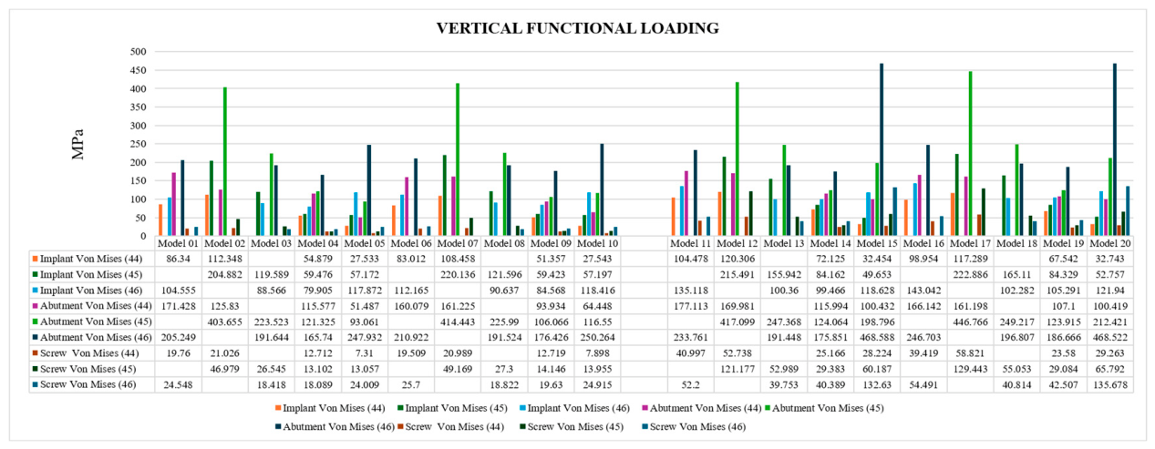
Figure 4.
Von Mises stress values in the implant, abutment, and screw of Models (01-20) under vertical parafunctional loading.
Figure 4.
Von Mises stress values in the implant, abutment, and screw of Models (01-20) under vertical parafunctional loading.
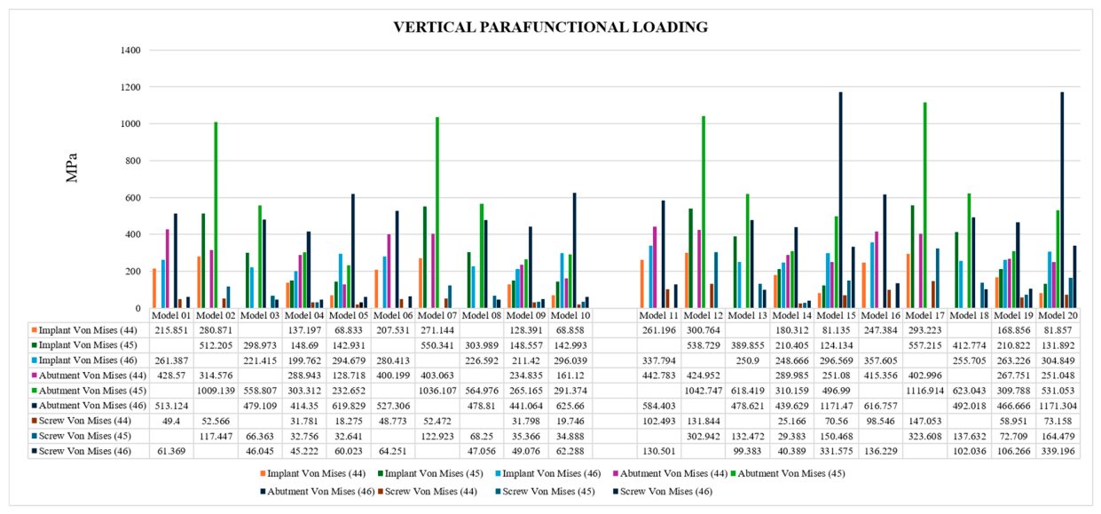
Figure 5.
Von Mises stress values in the implant, abutment, and screw of Models (01-20) under oblique functional loading.
Figure 5.
Von Mises stress values in the implant, abutment, and screw of Models (01-20) under oblique functional loading.
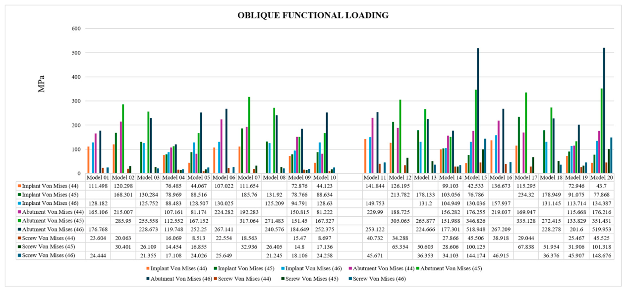
Figure 6.
Von Mises stress values in the implant, abutment, and screw of Models (01-20) under oblique parafunctional loading.
Figure 6.
Von Mises stress values in the implant, abutment, and screw of Models (01-20) under oblique parafunctional loading.
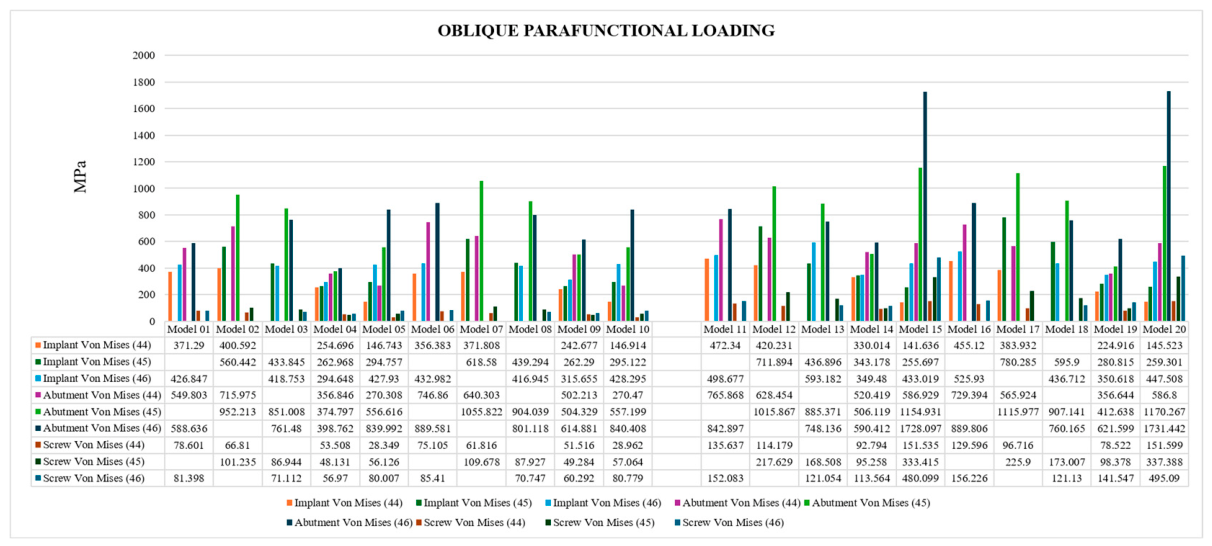
Figure 7.
Maximum and minimum principal stress values in the cortical and trabecular bone of Models (01-20) under vertical functional loading.
Figure 7.
Maximum and minimum principal stress values in the cortical and trabecular bone of Models (01-20) under vertical functional loading.
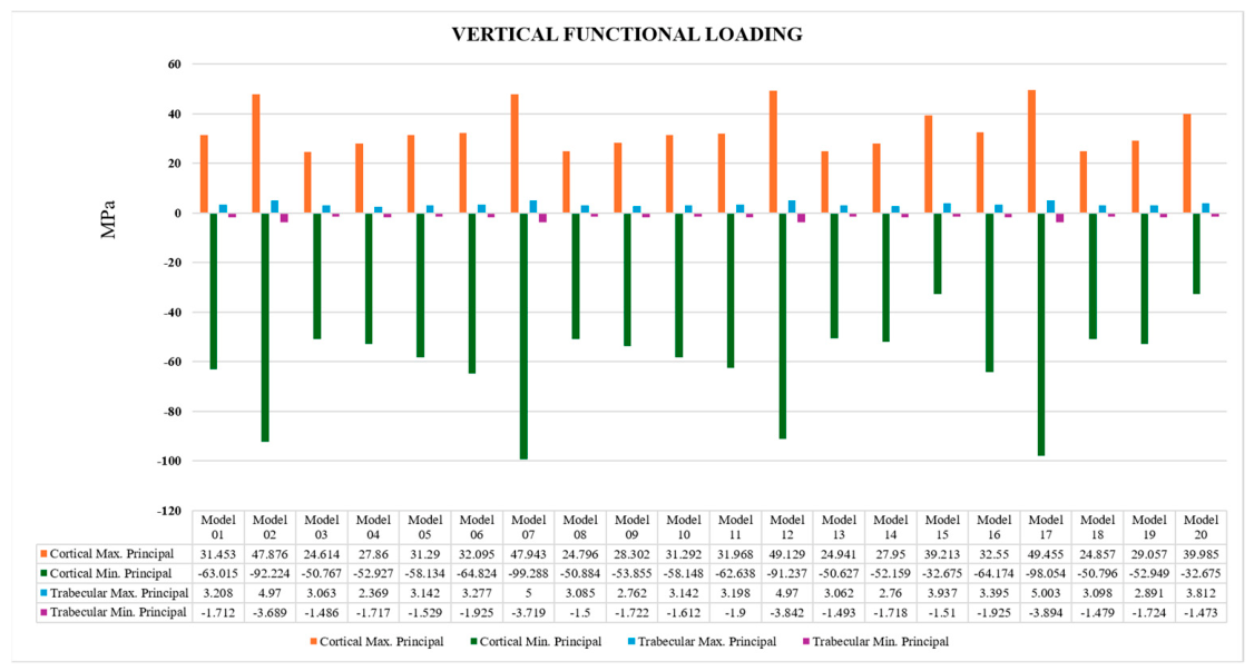
Figure 8.
Maximum and minimum principal stress values in the cortical and trabecular bone of Models (01-20) under vertical parafunctional loading.
Figure 8.
Maximum and minimum principal stress values in the cortical and trabecular bone of Models (01-20) under vertical parafunctional loading.
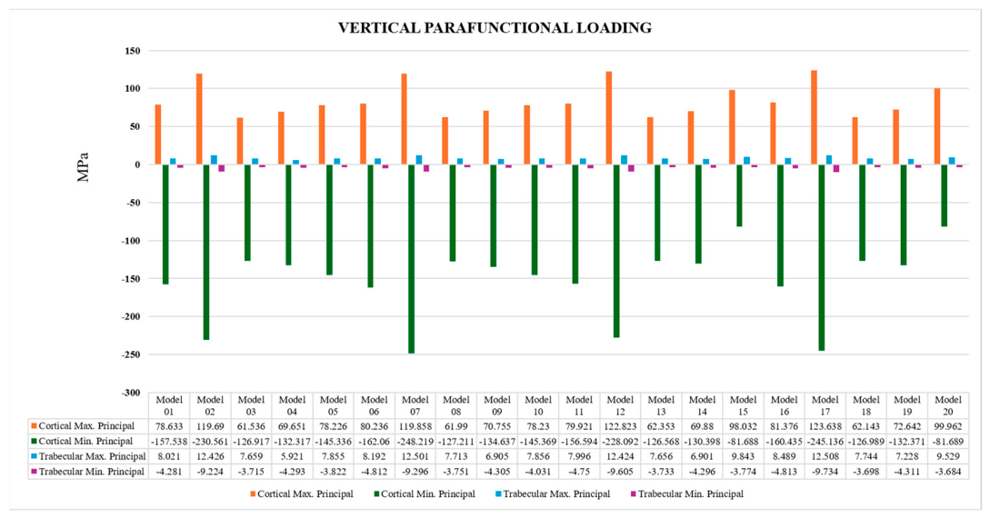
Figure 9.
Maximum and minimum principal stress values in the cortical and trabecular bone of Models (01-20) under oblique functional loading.
Figure 9.
Maximum and minimum principal stress values in the cortical and trabecular bone of Models (01-20) under oblique functional loading.
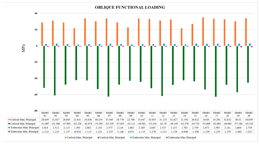
Figure 10.
Maximum and minimum principal stress values in the cortical and trabecular bone of Models (01-20) under oblique parafunctional loading.
Figure 10.
Maximum and minimum principal stress values in the cortical and trabecular bone of Models (01-20) under oblique parafunctional loading.
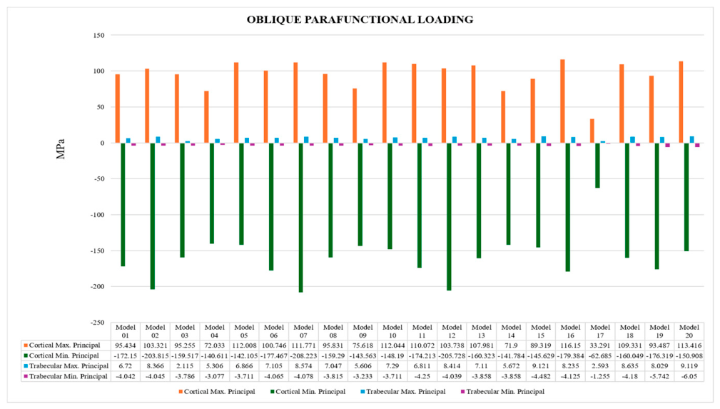
Figure 11.
Maximum and minimum principal stress values in the superstructure of Models (01, 06, 02, 07, 03, 08, 04, 09, 05, 10, 11, 16, 12, 17, 13, 18, 14, 19, 15, 20) under vertical functional loading.
Figure 11.
Maximum and minimum principal stress values in the superstructure of Models (01, 06, 02, 07, 03, 08, 04, 09, 05, 10, 11, 16, 12, 17, 13, 18, 14, 19, 15, 20) under vertical functional loading.

Figure 12.
Maximum and minimum principal stress values in the superstructure of Models (01, 06, 02, 07, 03, 08, 04, 09, 05, 10, 11, 16, 12, 17, 13, 18, 14, 19, 15, 20) under vertical parafunctional loading.
Figure 12.
Maximum and minimum principal stress values in the superstructure of Models (01, 06, 02, 07, 03, 08, 04, 09, 05, 10, 11, 16, 12, 17, 13, 18, 14, 19, 15, 20) under vertical parafunctional loading.
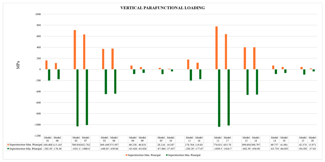
Figure 13.
Maximum and minimum principal stress values in the superstructure of Models (01, 06, 02, 07, 03, 08, 04, 09, 05, 10, 11, 16, 12, 17, 13, 18, 14, 19, 15, 20) under oblique functional loading.
Figure 13.
Maximum and minimum principal stress values in the superstructure of Models (01, 06, 02, 07, 03, 08, 04, 09, 05, 10, 11, 16, 12, 17, 13, 18, 14, 19, 15, 20) under oblique functional loading.
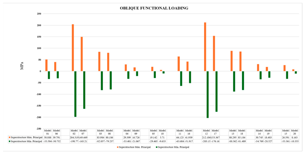
Figure 14.
Maximum and minimum principal stress values in the superstructure of Models (01, 06, 02, 07, 03, 08, 04, 09, 05, 10, 11, 16, 12, 17, 13, 18, 14, 19, 15, 20) under oblique parafunctional loading.
Figure 14.
Maximum and minimum principal stress values in the superstructure of Models (01, 06, 02, 07, 03, 08, 04, 09, 05, 10, 11, 16, 12, 17, 13, 18, 14, 19, 15, 20) under oblique parafunctional loading.
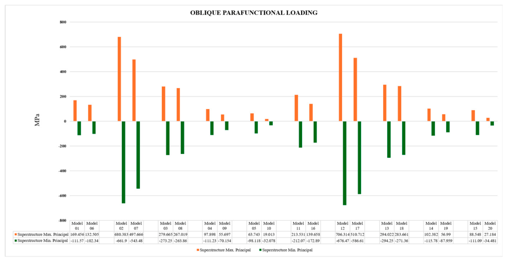

Table 1.
Model groups and prosthetic variables evaluated in the study.
| Model | Abutment System | Superstructure Material | Prosthetic Design |
|---|---|---|---|
| Model 01 | Multi-unit | Monolithic zirconia | Pontic (2 implants) |
| Model 02 | Multi-unit | Monolithic zirconia | Distal cantilever (2 implants) |
| Model 03 | Multi-unit | Monolithic zirconia | Mesial cantilever (2 implants) |
| Model 04 | Multi-unit | Monolithic zirconia | Splinted (3 implants) |
| Model 05 | Multi-unit | Monolithic zirconia | Non-splinted (3 implants) |
| Model 06 | Multi-unit | Zirconia framework with porcelain | Pontic (2 implants) |
| Model 07 | Multi-unit | Zirconia framework with porcelain | Distal cantilever (2 implants) |
| Model 08 | Multi-unit | Zirconia framework with porcelain | Mesial cantilever (2 implants) |
| Model 09 | Multi-unit | Zirconia framework with porcelain | Splinted (3 implants) |
| Model 10 | Multi-unit | Zirconia framework with porcelain | Non-splinted (3 implants) |
| Model 11 | Ti-base | Monolithic zirconia | Pontic (2 implants) |
| Model 12 | Ti-base | Monolithic zirconia | Distal cantilever (2 implants) |
| Model 13 | Ti-base | Monolithic zirconia | Mesial cantilever (2 implants) |
| Model 14 | Ti-base | Monolithic zirconia | Splinted (3 implants) |
| Model 15 | Ti-base | Monolithic zirconia | Non-splinted (3 implants) |
| Model 16 | Ti-base | Zirconia framework with porcelain | Pontic (2 implants) |
| Model 17 | Ti-base | Zirconia framework with porcelain | Distal cantilever (2 implants) |
| Model 18 | Ti-base | Zirconia framework with porcelain | Mesial cantilever (2 implants) |
| Model 19 | Ti-base | Zirconia framework with porcelain | Splinted (3 implants) |
| Model 20 | Ti-base | Zirconia framework with porcelain | Non-splinted (3 implants) |
Table 2.
Mechanical Properties Ascribed to Materials in the Model.
| Material | Elastic Modulus (MPa) | Poisson's Ratio References |
|---|---|---|
| Monolithic Zirconia | 210,000 | 0.30 [16] |
| Titanium | 110,000 | 0.35 [17] |
| Feldspathic Porcelain | 82,800 | 0.35 [18] |
| Resin Cement | 18,600 | 0.28 [19] |
| Cortical Bone | 13,700 | 0.30 [17] |
| Trabecular Bone | 1,370 | 0.30 [17] |
Table 3.
Static loading scenarios applied in the study and force distributions by region.
| Scenario Type | Force Direction | 1st Premolar | 2nd Premolar | 1st Molar | Total Force |
|---|---|---|---|---|---|
| 1. Functional | Vertical (Axial) | 80 N (2 points) | 120 N (2 points) | 200 N (4 points) | 400 N |
| 2.Parafunctional | Vertical (Axial) | 200 N (2 points) | 300 N (2 points) | 500 N (4 points) | 1000 N |
| 3. Functional | Oblique (30°)* | 30 N (2 points) | 45 N (2 points) | 75 N (4 points) | 150 N |
| 4.Parafunctional | Oblique (30°)* | 100 N (2 points) | 150 N (2 points) | 250 N (4 points) | 500 N |
Table 4.
Models exhibiting the maximum stresses generated in the components according to loading conditions and their values (MPa) .
Table 4.
Models exhibiting the maximum stresses generated in the components according to loading conditions and their values (MPa) .
| Component | Vert. Functional (MPa) | Model Configuration | Vert. Parafunctional (MPa) | Model Configuration | Oblique Functional (MPa) | Model Configuration | Oblique Parafunctional (MPa) | Model Configuration |
|---|---|---|---|---|---|---|---|---|
| Implant | 222.886 | M17 (TB, Zr-P, Distal cantilever) | 557.215 | M17 (TB, Zr-P, Distal cantilever) | 234.320 | M17 (TB, Zr-P, Distal cantilever) | 780.285 | M17 (TB, Zr-P, Distal cantilever) |
| Abutment | 468.588 | M15 (TB, MZ, Unsplinted 3 imp) | 1171.470 | M15 (TB, MZ, Unsplinted 3 imp) | 519.953 | M20 (TB, MZ, Unsplinted 3 imp) | 1731.442 | M20 (TB, MZ, Unsplinted 3 imp) |
| Screw | 135.678 | M20 (TB, Zr-P, Unsplinted 3 imp) | 339.196 | M20 (TB, Zr-P, Unsplinted 3 imp) | 148.676 | M20 (TB, Zr-P, Unsplinted 3 imp) | 495.090 | M20 (TB, Zr-P, Unsplinted 3 imp) |
| Cortical Bone | 99.288 | M07 (MU, Zr-P, Distal cantilever) | 248.219 | M07 (MU, Zr-P, Distal cantilever) | 62.685 | M17 (TB, Zr-P, Distal cantilever) | 208.223 | M07 (MU, Zr-P, Distal cantilever) |
| Trabecular Bone | 5.000 | M07 (MU, Zr-P, Distal cantilever) | 12.508 | M17 (TB, Zr-P, Distal cantilever) | 2.739 | M15 & M20 (Unsplinted 3 imp) | 9.121 | M15 (TB, MZ, Unsplinted 3 imp) |
| Superstructure | 412.506 | M02 (MU, MZ, Distal cantilever) | 1039.507 | M12 (TB, MZ, Distal cantilever) | 212.106 | M12 (TB, MZ, Distal cantilever) | 706.314 | M12 (TB, MZ, Distal cantilever) |
Mpa: Megapascal, TB: Titanium Base, MU: Multi-unit, MZ: Monolithic Zirconia, Zr-P: Porcelain-veneered Zirconia.
Disclaimer/Publisher’s Note: The statements, opinions and data contained in all publications are solely those of the individual author(s) and contributor(s) and not of MDPI and/or the editor(s). MDPI and/or the editor(s) disclaim responsibility for any injury to people or property resulting from any ideas, methods, instructions or products referred to in the content. |
© 2026 by the authors. Licensee MDPI, Basel, Switzerland. This article is an open access article distributed under the terms and conditions of the Creative Commons Attribution (CC BY) license.
Copyright: This open access article is published under a Creative Commons CC BY 4.0 license, which permit the free download, distribution, and reuse, provided that the author and preprint are cited in any reuse.


