Submitted:
21 January 2026
Posted:
22 January 2026
You are already at the latest version
Abstract
This study proposes and investigates a modular assembled steel-UHPC composite cable bridge consisting of upper prefabricated UHPC ducts and a steel truss underneath. Finite element (FE) analysis is conducted to investigate the mechanical performance of the medium-span (L=36m) cable bridge under service-loading conditions. The FE results indicate that under combined action of vertical and horizontal loads, the tensile damage in the UHPC ducts reaches approximately 10%, mainly concentrated near the end-support sections. The peak stress in the steel truss is far below its yield strength. The peak vertical displacement of the bridge is approximately L/225, below allowable limit of L/150, and the peak horizontal displacement is negligible. A parametric analysis is performed for web sections in the midspan and end of the cable bridge. Results show that the peak stress located at the lower chord increases with larger midspan web section. The increase in the midspan web section triggered a stress redistribution in the end webs and, consequently, a rise in the peak stress under the same load case; the peak vertical displacement decreases while the horizontal displacement exhibits marginal change. Considering the structural performance and economic efficiency, the web sections in the end may be appropriately reduced.
Keywords:
modular assembled cable bridge
; steel-UHPC composite cable bridge
; UHPC duct
; steel truss
1. Introduction
China’s ultra-high-voltage (UHV) power grid construction reached a critical milestone in 2025. To date, a total of 45 UHV transmission projects have been commissioned nationwide, forming the world’s largest and most technologically advanced long-distance power transmission network. This network serves as the backbone of China’s electricity transmission system, delivering abundant electrical energy across vast distances to load centers and ensuring a stable and reliable power supply. Nevertheless, during the pivotal transition from a conventional power system to a new-type power system dominated by renewable energy, the upgrading and expansion of transmission network infrastructure continue to face multiple challenges [1,2,3,4].
The cable laying methods in China mainly include direct burial, cable duct systems, cable tunnels/utility tunnels, cable trenches, and overhead lines. Chong et al. [5] used a full-scale chamber to replicate field construction for examining the mechanical response of direct-buried cables subjected to repetitive loads. Their observations showed that repetitive loading densified the soil around the cable, increasing stress on the cable and accumulating vertical strain. The trends were more pronounced with lower initial relative compaction. The shear wave velocity increases during repetitive loading, suggesting a change in the earth pressure coefficient. Wang et al. [6] proposed a new monitoring approach based on a sensor-enabled piezoelectric geocable (SPGC) to assess buried pipeline bending deformation. The overhead pipeline tests demonstrated that the SPGC system enables real-time, distributed, and energy-autonomous monitoring of buried pipeline deformation, which demonstrated the potential of the SPGC-based monitoring technique for long-term buried pipeline integrity assessment, providing critical deformation data for structural health assessment. Liu et al. [7] conducted shear tests on small-scale and full-scale concrete cable duct specimens reinforced with GFRP bars. The experimental results demonstrated that the shear capacity of the novel GFRP-reinforced concrete cable duct specimens increased with increasing transverse reinforcement ratio and longitudinal reinforcement ratio. Based on a comparative analysis of relevant international design codes, a shear design calculation method was proposed for GFRP-reinforced concrete cable ducts. Xu et al. [8] studied the temperature distribution characteristics of near-wall cable fires in urban tunnels through a series of reduced-scale fire tests. These test findings revealed that the cable’s proximity to the wall significantly influenced the fire temperature field. Zhu et al. [9] investigated the structural response of socket-jointed jacked cable tunnels subjected to differential ground settlement. Based on the interaction between a typical cable tunnel structure and the surrounding soil, and considering various relative positions between the tunnel and the settlement-induced deformation, a theoretical calculation model for the bending moment distribution and joint shear force of cable tunnels was established, providing a theoretical basis for deformation and damage assessment of cable tunnels in soft soil regions. Wang et al. [10], based on the Timoshenko beam theory and the finite difference method, proposed a finite difference-based theoretical approach for analyzing the flexural response of cable tunnels under tunnel-induced disturbances. Liu et al. [11], delved soil-structure interaction (SSI) effect on the seismic performance and failure mechanism of an overhead transmission lines (OTLs) subjected to depth-varying ground motions (DVGMs). The results exposed the potential of the SSI effect to weaken the seismic capacity of the OTL and increase the risk of failure, while disregarding the DVSE is likely to lead to overestimated outcomes. Lv et al. [12], studied the equivalent bending stiffness of the conductor near the suspension points of tension towers using a large sparse solution matrix-based computational method. The analysis results indicated that within the scope of the calculated breaking force, the equivalent bending stiffness decreased with the increase of constraint length, and which increased with the increased of tension; As the number of broken strands increased, it presented a downward tendency, and as the horizontal coordinates of broken strands increased, it presented a trend of first decreasing and then increasing.
The development of new-type power systems, particularly large-scale renewable energy transmission and urban power grid upgrading, has imposed unprecedented requirements on ultra-long-distance cable transmission. Conventional power grid construction technologies are constrained by technological limitations, long construction periods, significant environmental impacts, and high resource consumption, making them inadequate to meet the demands of environmentally friendly, intelligent, and highly resilient power systems. In light of this, prefabricated construction technologies that align with modern engineering requirements characterized by standardized prefabrication, rapid assembly, energy efficiency, environmental sustainability, and recyclability have gradually become a mainstream choice in power grid engineering projects [13]. Xu et al., [14] proposed a novel prefabricated UHPC cable trench and conducted flexural performance tests on the side panels as well as joint tests. The results indicated that the ultimate bearing capacity of the bolted bottom plate connection was approximately twice that of the socket-type joint specimens, ensuring the overall load-bearing performance of the UHPC prefabricated cable trench system.
Existing studies have predominantly focused on a single cable installation method. In contrast, this study integrates cable duct systems with overhead lines by forming a composite structure consisting of prefabricated modular UHPC cable ducts and a steel truss, enabling standardized prefabrication, regulated production, and convenient assembly. To investigate the structural performance of the modular assembled cable bridge, finite element analyses were conducted to evaluate its bearing capacity and serviceability performance under vertical and horizontal loading conditions, thereby providing a fundamental basis for the design and application of the proposed modular assembled cable bridge system.
2. Modular Assembled Cable Bridge
The modular assembled cable bridge is an assembled steel truss-UHPC composite bridge girders, as shown in Figure 1. The cable bridge is composed of several standardized modular units connected by high-strength bolts. Each modular unit mainly consists of a standardized steel truss member and a prefabricated UHPC unit for cable duct connected by shear studs, as shown in Figure 2. The shear studs are welded onto the top surface of the upper chord in the steel truss member. These headed studs provide composite action between the UHPC unit and the steel truss member through pouring UHPC into prefabricated openings in the shear connects region in the UHPC unit. The upper prefabricated UHPC unit comprises a prefabricated UHPC cover slab and a U-shaped prefabricated UHPC cable duct. The installation of individual components and the connection methods between components are described in detail in subsequent sections.
2.1. Standardized Steel Truss
The standardized steel truss member can be divided into three parts: the main truss, the lateral truss, and the upper and lower chord bracing system, as shown in Figure 3. Each main truss is fabricated by welding the upper chord, lower chord, and web members together. Moreover, the shear studs welded on the top surface of the upper chord are to connect with the upper UHPC cable duct. End plates are welded to both ends of the upper and lower chords for connecting to the lateral truss using high-strength bolts. Each lateral truss is composed of a transverse web member system welded to four short chord segments.
Prior to the fabrication of the upper and lower chord bracing system, the main truss and lateral truss are assembled and positioned to ensure the stability of the main truss. Subsequently, in-plane transverse braces and diagonal braces of the upper and lower chords are welded to complete the fabrication of the steel truss member, as shown in Figure 4. Various functional requirements specifically in the span can be satisfied by assembling multiple steel truss members, thereby forming steel truss members suitable for multi-scenario applications, as illustrated in Figure 5.
2.2. Prefabricated UHPC Unit for Cable Ducts
The prefabricated UHPC unit adopts a prefabrication UHPC cable duct with a U-channel-shaped and chevron-shaped UHPC cover plates, as shown in Figure 6. Longitudinal stiffening ribs are provided at the internal bottom surface of the U-shaped UHPC cable duct, as shown in Figure 7. At least two longitudinal stiffening ribs are positioned to align with the shear stud rows on the steel truss member. This is because that pronounced shear lag effects may occur in the concrete slab which serves as the upper flange in terms of the steel-concrete composite structures [15,16,17]. This shear lag effect results in maximum normal stress in the concrete slab being concentrated near the intersection with the web. Such nonuniform stress distribution may induce local damage prevented through the setting of the longitudinal ribs. Besides, multiple longitudinal stiffening ribs may be arranged along the bottom surface of the cable duct acting as cable separators. Prefabricated openings for shear studs are reserved within the longitudinal stiffening ribs. After assembly with the steel truss member, high-strength grout is cast into the stud openings. Upon completion of the grout curing, the prefabricated UHPC unit and the steel truss act integrally to form a composite structure.
Adjacent chevron-shaped UHPC cover plates are connected through a tongue-and-groove joint, while the lateral movement of the cover plates is restrained by protruding strips, as shown in Figure 8. This design facilitates cable installation during the construction stage and enables convenient inspection and maintenance during the service life.
Efficient and reliable connection methods are among the key factors enabling modular concrete structures to fully exploit their advantages in rapid construction, low energy consumption, and high quality. As a dry connection technique, bolted connections can effectively realize the potential benefits of prefabricated concrete structures and have therefore become a major focus of research on fully assembled concrete systems [18,19,20]. Therefore, bolted connections are adopted for the joints between the prefabricated UHPC cable ducts, as shown in Figure 9.
The end sections of the prefabricated cable duct are locally strengthened to provide sufficient contact area and operational space for connecting, thereby forming concrete connection flanges at the duct ends. Several countersunk holes are reserved within the flange to accommodate high-strength bolts, and steel washers are placed between the bolt nuts and the concrete to prevent local crushing. After completion of the bolted assembly, the joints are sealed with grout.
3. Design of the 36-m Span Modular Assembled Cable Bridge
Taking a medium-span bridge in the Hubei region in China as an example, a 36-m span modular assembled cable bridge was designed, as shown in Figure 10. The 36-m span cable bridge mainly consisted of six modular units, comprising two end units and four central units. The end units differed from the central units in that their diagonal web members were locally strengthened.
The elevation and cross-sectional views of the 36-m span modular assembled cable bridge were shown in Figure 11 (a) and (b), respectively. As illustrated, each modular unit spanned 6000 mm, with a total section height of 2004 mm and an overall width of 1850 mm.
In summary, the 36-m span modular assembled cable bridge was primarily composed of six 6-m modular units of two types, each consisting of a standardized steel truss and prefabricated UHPC unit. Hence, the design of the modular assembled cable bridge on these two components with the dimensions and cross-sectional types detailed in subsequent sections.
3.1. Prefabricated Steel Truss Component
The standardized steel truss member primarily consists of the main truss, lateral truss, and the upper and lower chord bracing system, as shown in Figure 3. The chord members were fabricated from rectangular hollow sections, while the web members used square hollow sections. All steel members were made of Q345 steel. These section types provided a lightweight structural system with convenient installation, reduced labor and material consumption, and shortened construction duration, thereby effectively lowering overall costs.
The main trusses were categorized into two types of trusses in the end and central module. Taking the main truss in the end module as an example, detailed dimensions were provided in Figure 12. For the main truss in the central module, all diagonal web members had cross-sectional dimensions of 80 mm×80 mm×3 mm square hollow sections, i.e., web member ② (See Figure 12).
The composite action between the prefabricated steel truss member and the UHPC unit are realized through the shear studs, as shown in Figure 2 (b). The shear studs were cylindrical headed studs made of ML15 material, having a diameter of 19 mm and a height of 80 mm (Φ19 × 80 studs). According to the fully shear-resistant connection referring to JGJ 138-2016 code for design of composite structures [21], the longitudinal spacing of the studs was calculated to be 300 mm. These studs were arranged symmetrically along the span direction, and their layout was shown in Figure 13. Due to the page width limitation, only the half-span steel truss was presented here to illustrate the details.
The detailed dimensions of the lateral truss were presented in Figure 14, while the detailed dimensions of the upper and lower chord planes were shown in Figure 15.
The fabrication and welding of the steel truss components can be completed in factories and subsequently transported to project site for assembly. As previously described, the 36-m span modular assembled cable bridge consists of six modular units. At the construction site, the six standardized steel truss member are sequentially lifted into position, and then these truss members are connected using M22 high-strength bolts of grade 10.9.
3.2. Prefabricated UHPC Unit
The prefabricated UHPC unit primarily consists of the U-shaped UHPC cable duct and the chevron-shaped UHPC cover plate, as shown in Figure 6. The UHPC cable ducts were reinforced with HRB400 rebars, all with a diameter of 8 mm. Detailed dimensions of the prefabricated chevron-shaped UHPC cover plate and UHPC cable duct were shown in Figure 16 and Figure 17, respectively.
4. Modeling of FE Models
Numerical simulations were conducted to evaluate the structural performance of the 36-m span modular assembled cable bridge under representative loading conditions. In this study, the upper UHPC cable ducts served as the compressive components. Therefore, the mechanical behavior of the connections between them was not considered. The lower steel truss members were connected by 10.9 grade M22 high-strength bolts whose bearing capacity confirmed safety of the connections, allowing the prefabricated steel truss members to be considered as an integral steel truss. The chevron-shaped UHPC cover plates were regarded as non-structural components being neglected in FE modelling. But their self-weight was applied as an equivalent vertical load. Consequently, the FE model of the 36-m span modular assembled cable bridge consisted of a 36-m UHPC cable duct and steel truss, as illustrated in Figure 18. The detailed FE modeling procedures were presented in the subsequent sections.
4.1. Material Properties and Element Types
The material stress-strain relationships used in the FE analysis are shown in Figure 19. The constitutive behavior of the steel was modeled using a bilinear hardening model, with an elastic modulus E of 206000MPa and a Poisson’s ratio ν of 0.3; the hardening modulus was taken as 0.01E. The mechanical properties of the steel were summarized in Table 1. The von Mises yield criterion was adopted to define yielding. Furthermore, a kinematic hardening model was employed to account for Bauschinger effect.
The mechanical properties of UHPC are based on experimentally measured values reported in Ref. [22], as summarized in Table 2. The compressive stress-strain curve of UHPC consisted of three phases. The first phase corresponded to linear elastic behavior, in which the stress σ was up to 0.4fc, where fc was the prismatic compressive strength of UHPC. The second and third phases represented the nonlinear compressive behavior of UHPC. The complete compressive stress-strain relationship was described by the constitutive model proposed in Ref. [23], as expressed in Equation (1).
where, the CEB-FIP (1993) model was adopted for the ascending phases; ε0=3500με, ξ=ε/ε0 and n=Ec/Es; Ec was the elastic modulus of UHPC and Es was the secant modulus at the peak stress.
The axial tensile stress-strain behavior of UHPC was modeled using a triple-fold lines model, with the fiber characteristic parameter λf introduced to describe the contribution of steel fibers to the tensile performance of UHPC [24], as expressed in Equation (2).
where, εte, εtp and εtu denoted the elastic ultimate strain, peak strain, and ultimate strain in axial tension of UHPC, respectively; ft was the axial tensile strength of UHPC; ρf, lf and df represented the volume content, length, and diameter of steel fibers, respectively.
Concrete Damaged Plasticity (CDP) model was utilized to simulate the irreversible damage associated with concrete cracking and crushing. The CDP model parameters are adopted based on the recommended values in Ref. [25], as summarized in Table 3. The damage coefficient D is calculated as expressed in Equation (3).
here, σ and ε represent the compressive (or tensile) stress and strain of UHPC, respectively.
The prefabricated UHPC units were modeled using three-dimensional eight-node solid reduced integration element C3D8R, which were more suitable for bending-dominated loading conditions than fully integrated elements and offered higher computational efficiency. The steel truss was modeled using three-dimensional beam element B31. The rebars were modeled by three-dimensional truss elements T3D2. The mesh sizes were respectively 100mm, 50mm and 100mm for the above three instances.
4.2. Interaction and Boundary Condition
The modular assembled cable bridge in this study is a steel truss-UHPC composite structure, in which the prefabricated UHPC units are connected to the steel trusses via poring UHPC into the prefabricated openings positioned to align with the shear studs in the UHPC cable ducts. This connection represents one of the key aspects that need be carefully considered in the FE analysis. In FE analysis, shear connections can be simulated using various approaches, including spring elements, beam elements, combined spring-beam elements, and solid elements. After comparative evaluation, the nonlinear shear spring element was adopted to simulate the interfacial longitudinal slip behavior between the steel truss and UHPC cable duct [26]. The connector element CONN3D2 with Cartesian-Align type was employed, in which an axial nonlinear constitutive relationship needed to be defined to simulate the longitudinal slip. The nonlinear constitutive relationship followed the shear-slip model proposed by Ollgaard et al. [27,28]. For clarity, the UHPC cable duct was vertically offset by 200 mm to display the nonlinear springs, as shown in Figure 20. Hard contact was maintained in the normal direction between the top surface of the steel truss bracing plane and the bottom surface of the UHPC slab.
The boundary conditions for the 36-m span cable bridge were applied at the upper chords of the steel truss at both ends. The left end was modeled as a fixed hinge support, while the right end was modeled as a sliding hinge support.
According to GB 55001-2021 general code for engineering structures, the design loads were determined and converted into equivalent loads based on different load distribution and loading region. The values of equivalent loads were presented in Table 4.
Based on the installation and actual service conditions of the cable bridge, the primary load combination cases were summarized in Table 5.
5. FE Analysis of the 36-m Span Modular Assembled Cable Bridge
5.1. FE Analysis Results of the 36-m Span Modular Assembled Cable Bridge
Table 6 provides a summary of the FE analysis results i.e., the mechanical responses of the 36-m span cable bridge under all loading cases, including the maximum and minimum principal stress in UHPC, the peak von Mises stress of the steel truss, the peak vertical and horizontal displacements (VDs and HDs), and longitudinal slip (LS) between the upper UHPC ducts and lower steel truss members. Based on these results, loading cases were selected as the representative cases which exhibited both relatively larger vertical and horizontal displacements. Therefore, load case 9 was selected as the representative case for analyzing the mechanical response of the cable bridge.
The stress distribution in UHPC under load case 9 was shown in Figure 21. Stress contours of the UHPC cable duct in Case 9 (Unit: MPa): (a) maximum principal stress contour; (b) minimum principal stress contour.. The maximum principal stress occurred at the longitudinal stiffening rib of the section near the sliding hinge support, slightly exceeding the of UHPC tensile strength of 8 MPa. It indicated that minor damage was observed in UHPC in this region. The minimum principal stress was located at the top of the sidewall of the cable duct at midspan, with a stress value well below the compressive strength of UHPC. The tensile damage contour of UHPC was presented in Figure 22, indicating slight damage at the sections near both supports of the cable bridge, with a damage level of approximately 10.1%.
The von Mises stress distribution in the steel truss under load case 9 was shown in Figure 23. The maximum stress occurred at the joint between the web and chord members at midspan, reaching a peak value of 236 MPa, indicating that no yielding occurred.
The section force distribution in the steel truss was shown in Figure 24. The section force in the upper chord at midspan was -692 kN (the negative sign indicated compression). Assuming a uniform stress distribution over the cross-section, the corresponding compressive stress on this section was 150.4 MPa. Similarly, the section force in the lower chord at midspan was 848 kN, resulting in a tensile stress of 184.3 MPa. The peak in-plane shear force was 18.4 kN, while the horizontal transverse shear force reached 145 kN. Compared with the axial section force, the effect of shear can be neglected. According to GB 50017-2017 standard for design of steel structures, the tensile bearing capacity of a single 10.9-grade M22 high-strength bolt is 152 kN. The total bearing capacity of the bolts connecting at the lower chord joint was 973 kN, which exceeded the section force in the lower chord. It demonstrated that the simplified FE modeling approach was reasonable and effective.
The vertical displacement contour under load case 9 was shown in Figure 25. The maximum vertical deformation was observed at the mid-span section, reaching 161 mm (L/225), which was below the allowable limit of L/150. The out-of-plane displacement reached a peak of only 5.2 mm (L/9000), which was negligible.
5.2. FE Parametric Analysis
Based on the FE analysis results discussed above, load case 7 and 9 were selected as representative cases to conduct a parametric analysis of the 36-m span modular assembled cable bridge in this section, focusing on the influence of the web member cross-sectional dimensions, while all other parameters remained unchanged. In addition, the FE model of the cable bridge with a span of 30m was established for comparative analysis to assess the effect of span on the bearing performance. The parameters of each model and the corresponding analysis results were summarized in Table 7.
The parametric analysis results indicated that: (1) The cross-sectional dimensions of the web members had little effect on the stress response in the UHPC cable duct; (2) The peak stress in the steel truss increased with the increasing of the cross-sectional dimensions of the central diagonal webs. Taking load case 7 as an example, Figure 26 depicted the von Mises stress distribution in the steel truss (M36-1 to M36-3). As can be seen from Figure 26, The stress in the end diagonal webs redistributed as the cross-sectional dimensions of the central diagonal webs increased. The larger the cross-sectional dimensions of the central diagonal webs, the lower the stress in the end diagonal webs. This redistribution led to a rise in the peak stress in the lower chords under the same load case; (3) The peak vertical displacement decreased as the cross-sectional dimensions of the central diagonal webs rose, while the peak horizontal displacement showed no significant change; (4) Considering structural performance, economy, and environmental factors comprehensively, the cross-sectional dimensions of the end diagonal webs can be appropriately reduced; (5) The span-to-height ratio was one of the primary factors affecting the mechanical response of the modular assembled cable bridge, with a lower span-to-height ratio significantly reducing both the stress in the steel truss and maximum vertical displacement.
6. Conclusions
This study proposed the modular assembled cable bridge by integrating the prefabricated UHPC cable ducts with the steel truss, and conducted the FE analysis on the mechanical performance of the 36-m span cable bridge under representative loading cases. The main conclusions were as follows:
1) Under load case 7 (the most unfavorable combination of vertical loads), the maximum principal stress in the UHPC cable duct slightly exceeds the UHPC tensile strength of 8 MPa, while the minimum principal compressive stress was well below the compressive strength. The peak stress in the steel truss reached 235 MPa, with all steel members remaining elastic. The peak vertical displacement was approximately L/225, below the allowable limit of L/150.
2) Under load case 9 (the most unfavorable combination of vertical and horizontal loads), the maximum principal stress in UHPC slightly exceeded the tensile strength, with a tensile damage of 10%, concentrated at the longitudinal stiffening ribs on the sections at end supports. The minimum principal compressive stress remained well below the compressive strength. The steel truss experienced a peak stress of 236 MPa, with no yielding. The peak vertical displacement was approximately L/225, within the allowable limit of L/150, while the peak horizontal displacement was only L/9000, which was negligible.
3) With the increasing of the cross-sectional dimensions of the central diagonal webs, the peak stress in the steel truss increased whereas the peak vertical displacement decreased. This was because the stress in the end diagonal webs redistributed as the cross-sectional dimensions of the central diagonal webs increased, which led to a rise in the peak stress in the lower chords under the same load case; The peak horizontal displacement showed no significant change. Considering structural performance, economy, and environmental factors comprehensively, the cross-sectional dimensions of the end diagonal webs can be appropriately reduced.
4) The span-to-height ratio was one of the primary factors affecting the mechanical response of the modular assembled cable bridge. Reducing the span-to-height ratio can significantly decrease both the stress in the steel truss and maximum vertical displacement.
Author Contributions
Conceptualization, X.W. and D.L.; Methodology, X.W., Z.W. and L.T.; Software, Z.W., T.L. and W.Z.; Validation, X.W., D.L. and S.L.; Investigation, Z.W., T.L. and C.C.; Resources, X.W. and D.L.; Data curation, Z.W. and C.C.; Writing-original draft, Z.W.; Writing-review & editing, T.L., Z.W. and X.W.; Visualization, D.L. and C.T.; Supervision, D.L. and C.C. Project administration, X.W.; Funding acquisition, D.L. and L.T. All authors have read and agreed to the published version of the manuscript.
Funding
This research was funded by State Grid Huanggang Power Supply Company 2024 R&D and Application Project for New Types of Prefabricated Cable Bridge Systems (5215E0240008).
Institutional Review Board Statement
Not applicable.
Informed Consent Statement
Not applicable.
Data Availability Statement
Data will be made available on request.
Acknowledgments
The authors are grateful for the funding.
Conflicts of Interest
The authors declare no conflicts of interest.
References
- YU S, ZHOU S, DAI Y, et al. Impacts of RPS and FIT on inter-regional power transmission line layout in China: Considerations of high renewable energy penetration. Energy Policy. 2023, 178: 113615. [CrossRef]
- THOMAS A, MISHRA U. A green energy circular system with carbon capturing and waste minimization in a smart grid power management. Energy Rep. 2022, 8: 14102–23. [CrossRef]
- YANG SX, ZHU CX, QIAO L, et al. Dynamic assessment of Energy Internet’s emission reduction effect -- a case study of Yanqing, Beijing. J. Clean. Prod. 2020, 272: 122663. [CrossRef]
- FANG K, TANG Y, ZHANG Q, et al. Will China peak its energy-related carbon emissions by 2030? Lessons from 30 Chinese provinces. Appl. Energy. 2019, 255: 113852. [CrossRef]
- CHONG SH, AN JB, CHO GC. Full-scale test of Direct-buried Cable in Sand under Repetitive Loading. Transp. Geotech. 2022, 37: 100877. [CrossRef]
- WANG J, WAN L, CHEN K, et al. Experimental investigation on buried pipeline bending deformation monitoring using flexible piezoelectric sensing. Tunn. Undergr. Space Tech. 2026, 168: 107218. [CrossRef]
- LIU CB, WANG JY, CHEN Y, et al. Shear bearing capacity of concrete cable duct reinforced with GFRP bars. Acta Mater. Compos. Sin. 2018, 35 (12): 3331-3341. https://www.chndoi.org/Resolution/Handler?doi=10.13801/j.cnki.fhclxb.20180206.001.
- XU D, LI Y, YANG X, et al. Enhancing resilience in urban utility tunnels power transmission systems: Analysing temperature distribution in near-wall cable fires for risk mitigation. Tunn. Undergr. Space Tech. 2024, 152: 105911. [CrossRef]
- ZHU JJ, WANG XL, LI XR, et al. Mechanical damage analysis of cable tunnels constructed by pipe jacking method in soft soil under local differential settlement. J. Nanjing Tech Univ. (Nat. Sci. Ed.) 2025, 47(3): 279-287. https://link.cnki.net/urlid/32.1670.N.20250411.0940.002.
- WANG XL, ZHU JJ, YE MG, et al. Deflection analysis of cable tunnels due to underpass excavation in soft soils. J. Basic Sci. Eng. 2024, 32(04): 944-56. https://www.chndoi.org/Resolution/Handler?doi=10.16058/j.issn.1005-0930.2024.04.003.
- LIU J, MENG X, TIAN L, et al. Failure mechanisms and seismic fragility analysis of overhead transmission lines incorporating pile-soil-structure interaction. Eng. Fail. Anal. 2024, 160: 108201. [CrossRef]
- LV XF, MA XQ, ZHU CS. Research on equivalent bending stiffness of conductor near the tension section suspension point of overhead transmission lines. Electr. Power Syst. Res. 2026, 254: 112617. [CrossRef]
- JU HT, ZHANG K, WANG XP, et al. Bending Test and FE Analysis of Novel Grouted Plug-in Connection for Prefabricated Assembled Raft Foundation. Buildings 2025, 15, 3931. [CrossRef]
- XU G, WANG XK, SHENG H, et al. Design and resistance performance of UHPC prefabricated cable trench. Bull. Chin. Ceram. Soc. 2022, 41(03): 844-52. https://www.chndoi.org/Resolution/Handler?doi=10.16552/j.cnki.issn1001-1625.20220112.007.
- ZHANG YF, TAN CJ, ZHAO H, et al. Experimental and numerical study of shear-lag effect on low-ribbed steel-UHPC composite structure. Structures 2022, 46: 395–407. [CrossRef]
- WANG CS, ZHANG WT, LI HT, et al. Shear lag effect of twin I-shaped composite girders in cable-stayed bridges. Thin-Walled Struct. 2022, 180: 109822. [CrossRef]
- CHEN Y, DONG J, XU T, et al. The shear-lag effect of composite box girder bridges with corrugated steel webs and trusses. Eng. Struct. 2019, 181: 617-28. [CrossRef]
- XIONG F, ZHANG D, RAN M, et al. Seismic performance of bolt-connected fully assembled concrete modular construction by full-scale shaking table test. Eng. Struct. 2025, 343: 121026. [CrossRef]
- XIONG F, ZHENG CY, LIU Y, et al. Deflection function of a novel bolt-connected precast concrete floor. Eng. Struct. 2025, 323: 119250. [CrossRef]
- XIONG F, WANG YH, WANG ZQ, et al. Seismic performance of coupled precast concrete wall panels connected by novel vertical bolted joints. Structures 2024, 70: 107654. [CrossRef]
- Ministry of Housing and Urban-Rural Development of China. Code for Design of Composite Structures GB 50017-2017; China Architecture & Building Press Beijing: Beijing, China, 2017.
- HE SH, ZHOU DF, BAI BS, et al. Experimental study on shear performance of prefabricated HSS-UHPC composite beam with perfobond strip connectors. Eng. Struct. 2025, 324: 119318. [CrossRef]
- TAN XY, FANG Z, YIN YB, et al. Shear behavior of low-profile perfobond strip connectors for steel–thin UHPC composite deck structures. Eng. Struct. 2025, 322: 119204. [CrossRef]
- SU J, CHEN JT, FANG Z, et al. Flexural performance and capacity calculation of unreinforced UHPC slabs. J. Hunan Univ. (Nat. Sci.) 2023, 50(05): 29-42. https://www.chndoi.org/Resolution/Handler?doi=10.16339/j.cnki.hdxbzkb.2023053.
- FAKEH M, JAWDHARI A, FAM A. Recommended concrete damage plasticity parameters and constitutive models for UHPC in ABAQUS. Eng. Struct. 2025, 333: 120154. [CrossRef]
- ZHOU HT, WANG ZZ, ZHANG SP, et al. Influence of accordion effect on fire resistance of prestressed steel-concrete composite beams with corrugated webs. J. Build. Struct. 2022, 43(08): 174-84+208. https://www.chndoi.org/Resolution/Handler?doi=10.14006/j.jzjgxb.2020.0534.
- OLLGAARD, J. G. Shear strength of stud connectors in lightweight and normal weight concrete, AISC Eng’g Jr., April 1971 (71-10), 1971. [CrossRef]
- ZHOU YJ, YANG X, ZOU WW, et al. Experimental testing and machine learning to predict the load-slip behavior of stud con-nectors in steel-UHPC composite structures. Eng. Struct. 2025, 335: 120418. [CrossRef]
Figure 1.
Assembled steel truss-UHPC composite bridge.
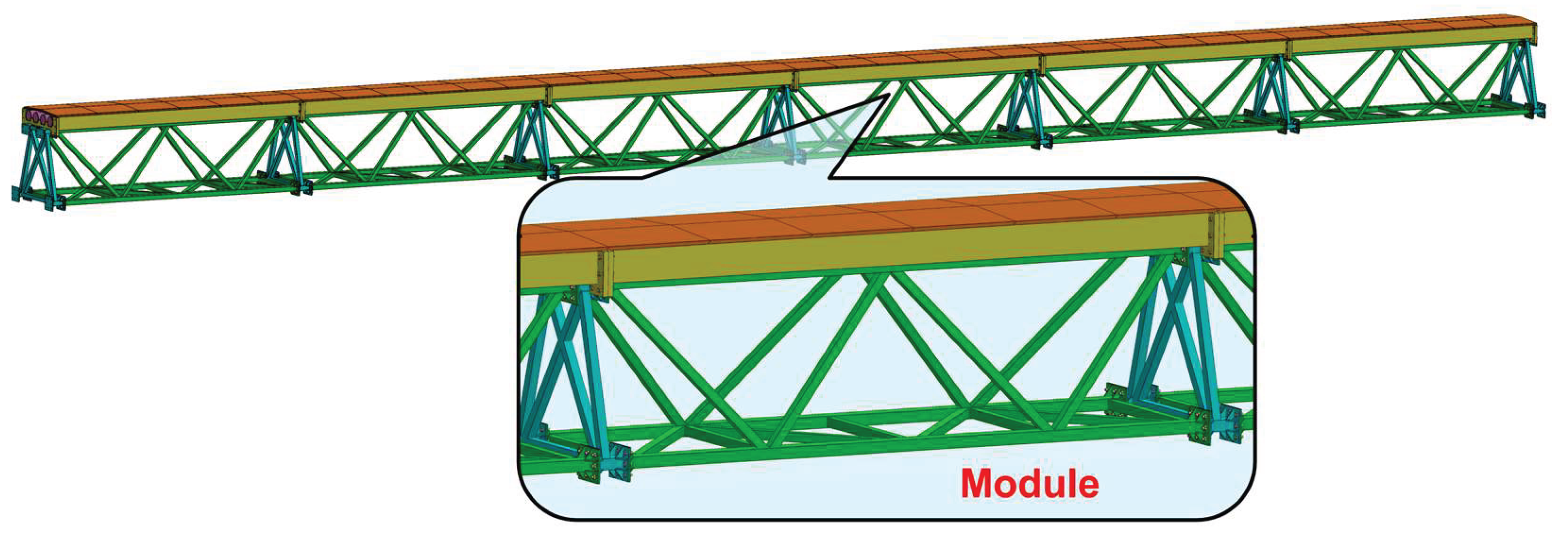
Figure 2.
The standardized module: (a) schematic of the assembled module; (b) exploded view of the module components.
Figure 2.
The standardized module: (a) schematic of the assembled module; (b) exploded view of the module components.
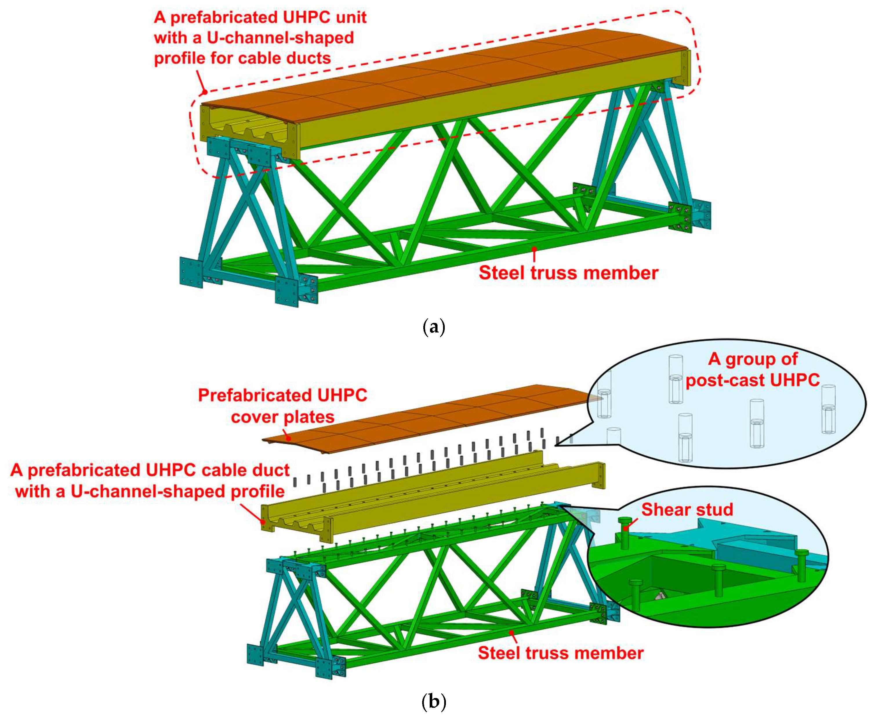
Figure 3.
Exploded view of the steel truss member.
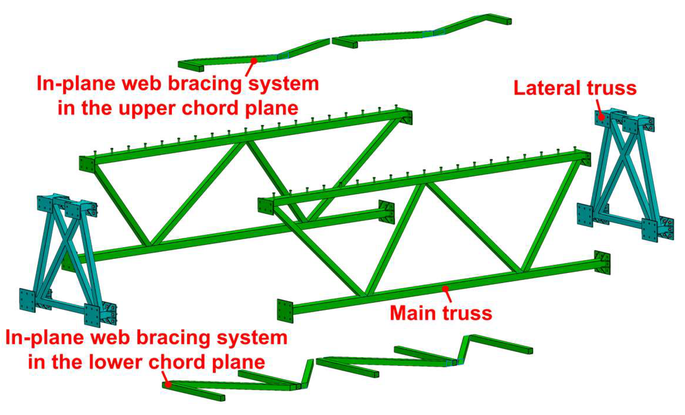
Figure 4.
The standardized steel truss member.
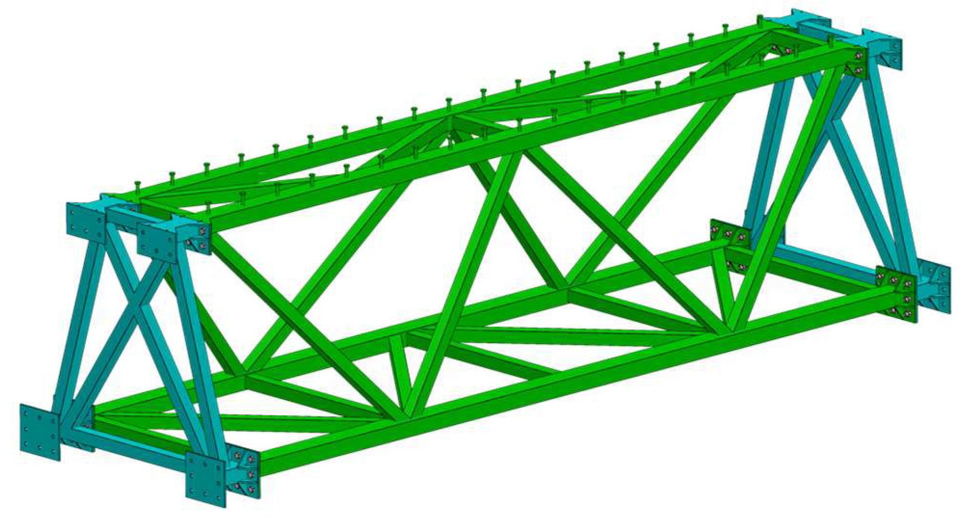
Figure 5.
The steel truss members adaptable to multi-scenario performance requirement.
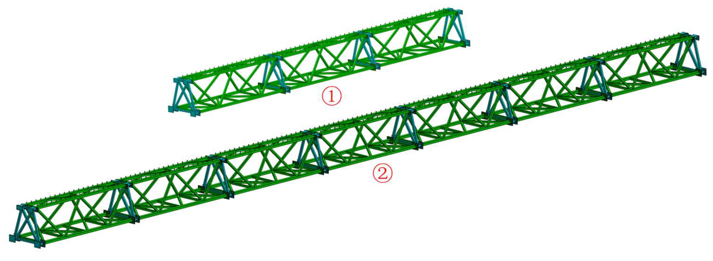
Figure 6.
The components of the prefabricated UHPC unit for cable ducts.
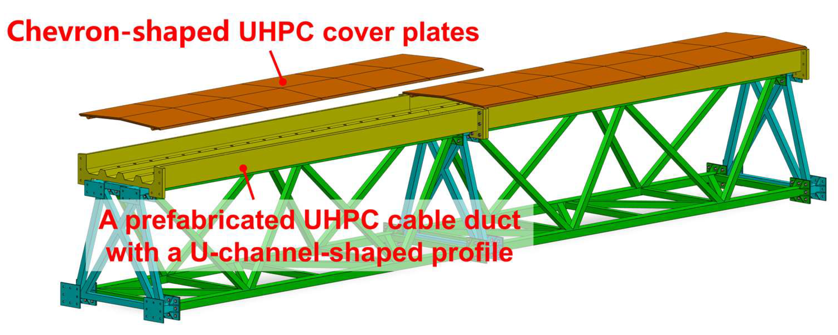
Figure 7.
The UHPC cable duct with a U-channel-shaped profile.
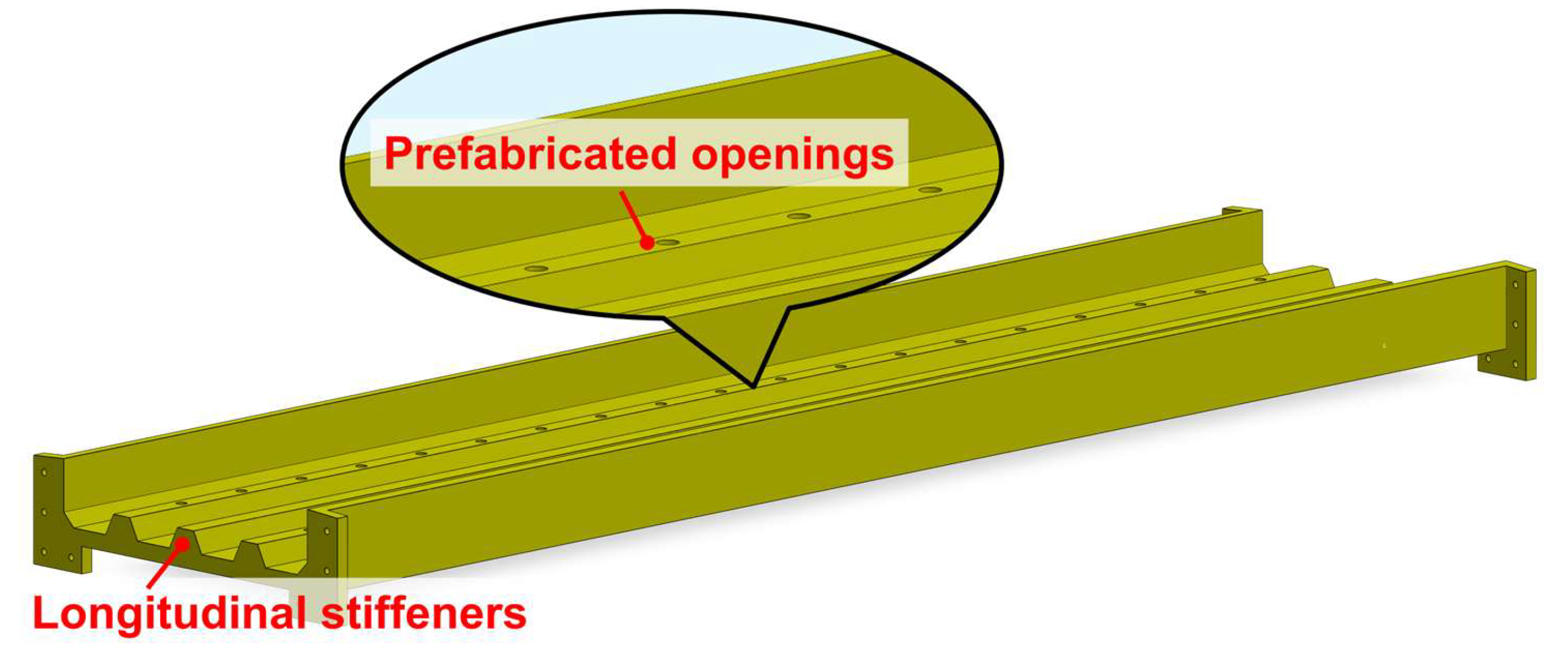
Figure 8.
The components of the prefabricated UHPC unit for cable ducts.
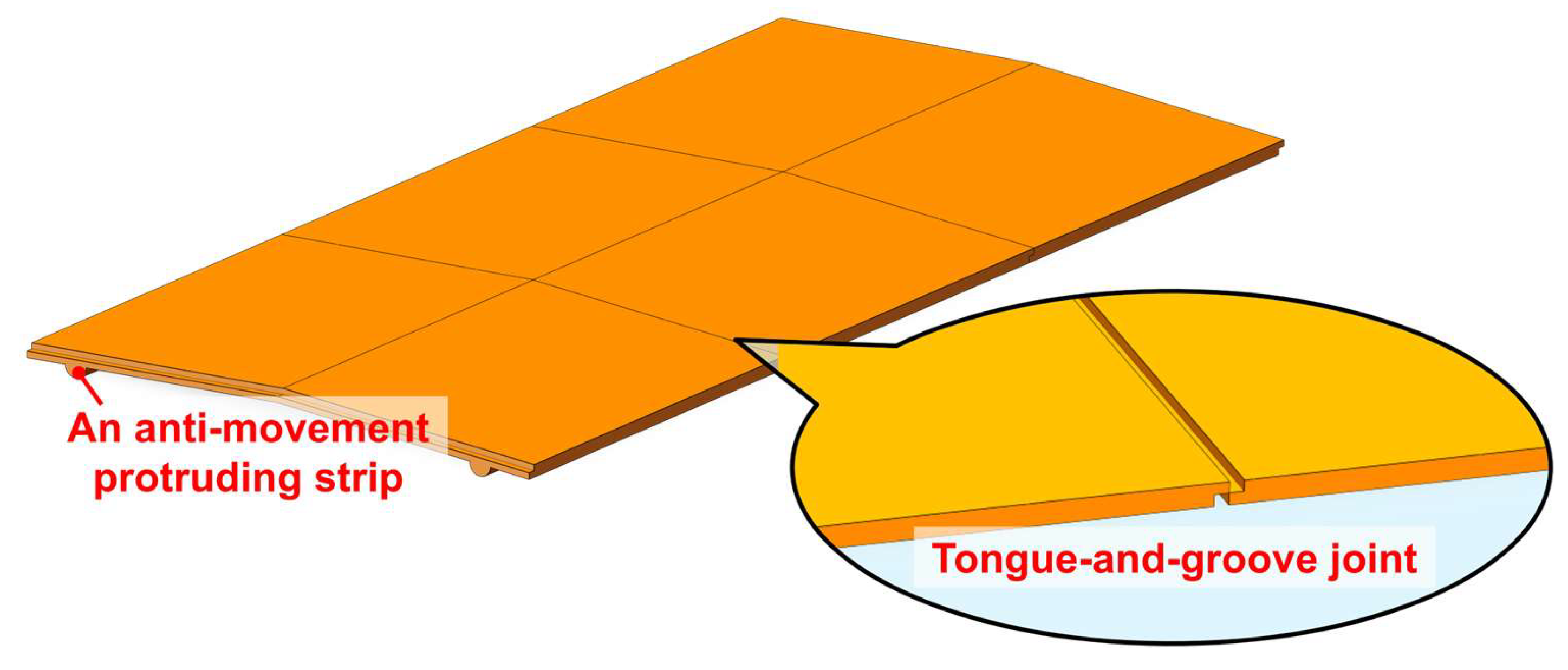
Figure 9.
The components of the prefabricated UHPC unit for cable ducts.
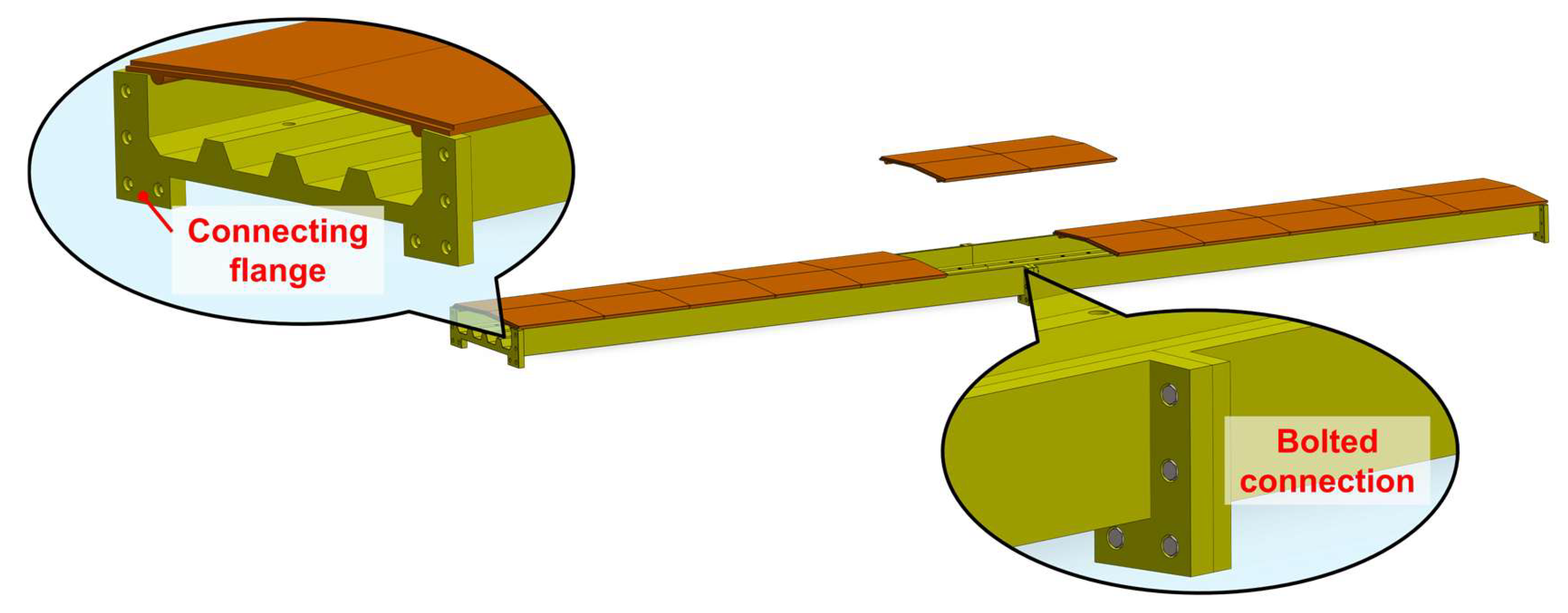
Figure 10.
A 36-m span assembled UHPC cable bridge: (a) two end modules and four central modules; (b) the end module.
Figure 10.
A 36-m span assembled UHPC cable bridge: (a) two end modules and four central modules; (b) the end module.
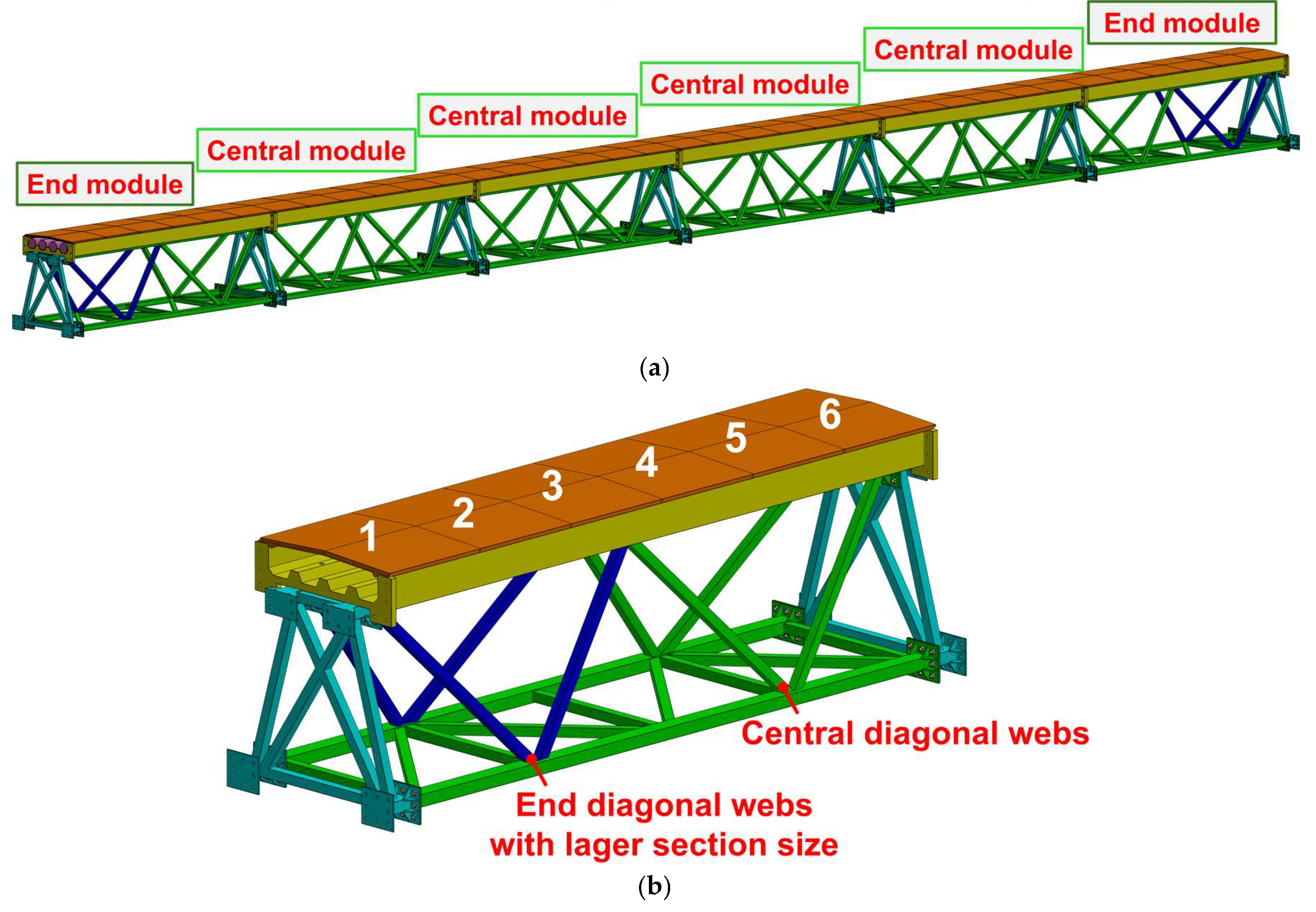
Figure 11.
Dimension drawing of the 36-m span assembled UHPC cable bridge (Unit: mm): (a) front view; (b) cross-section view.
Figure 11.
Dimension drawing of the 36-m span assembled UHPC cable bridge (Unit: mm): (a) front view; (b) cross-section view.
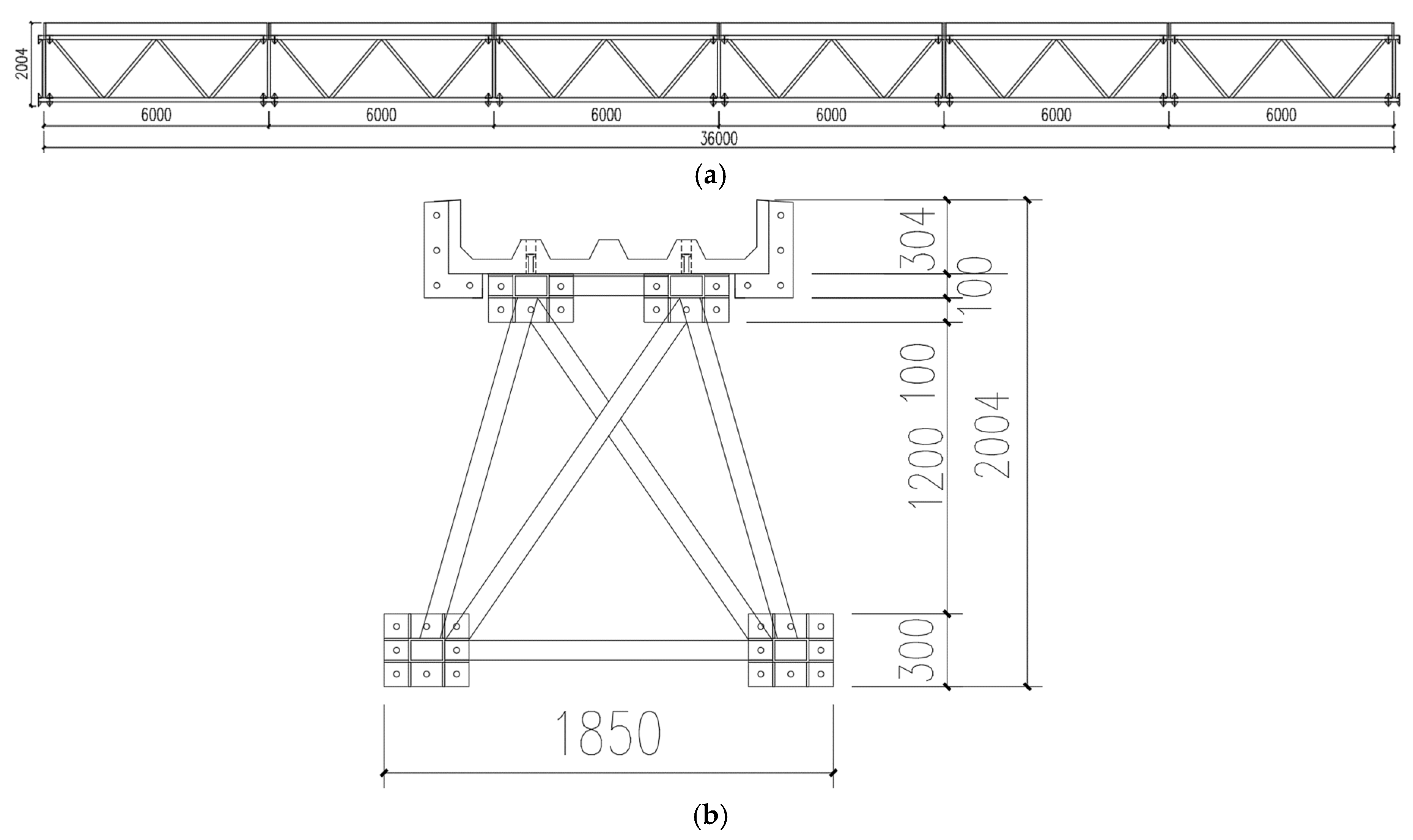
Figure 12.
Dimension drawing of the main truss in the end module (Unit: mm).
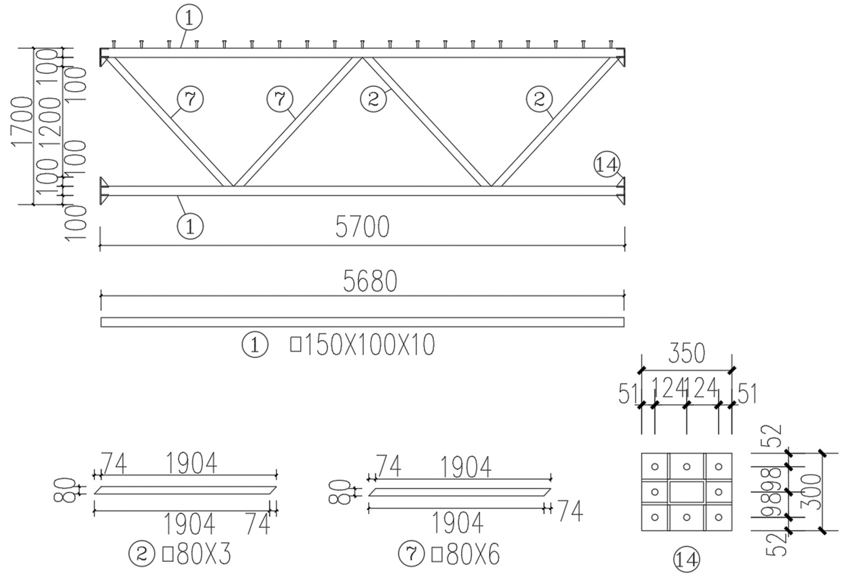
Figure 13.
Arrangement diagram of the shear studs in the upper chord plane (Unit: mm).
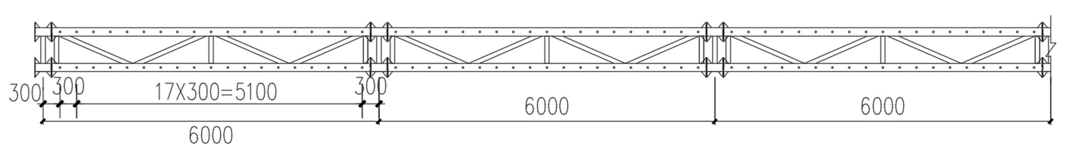
Figure 14.
Dimension drawing of the lateral truss (Unit: mm).
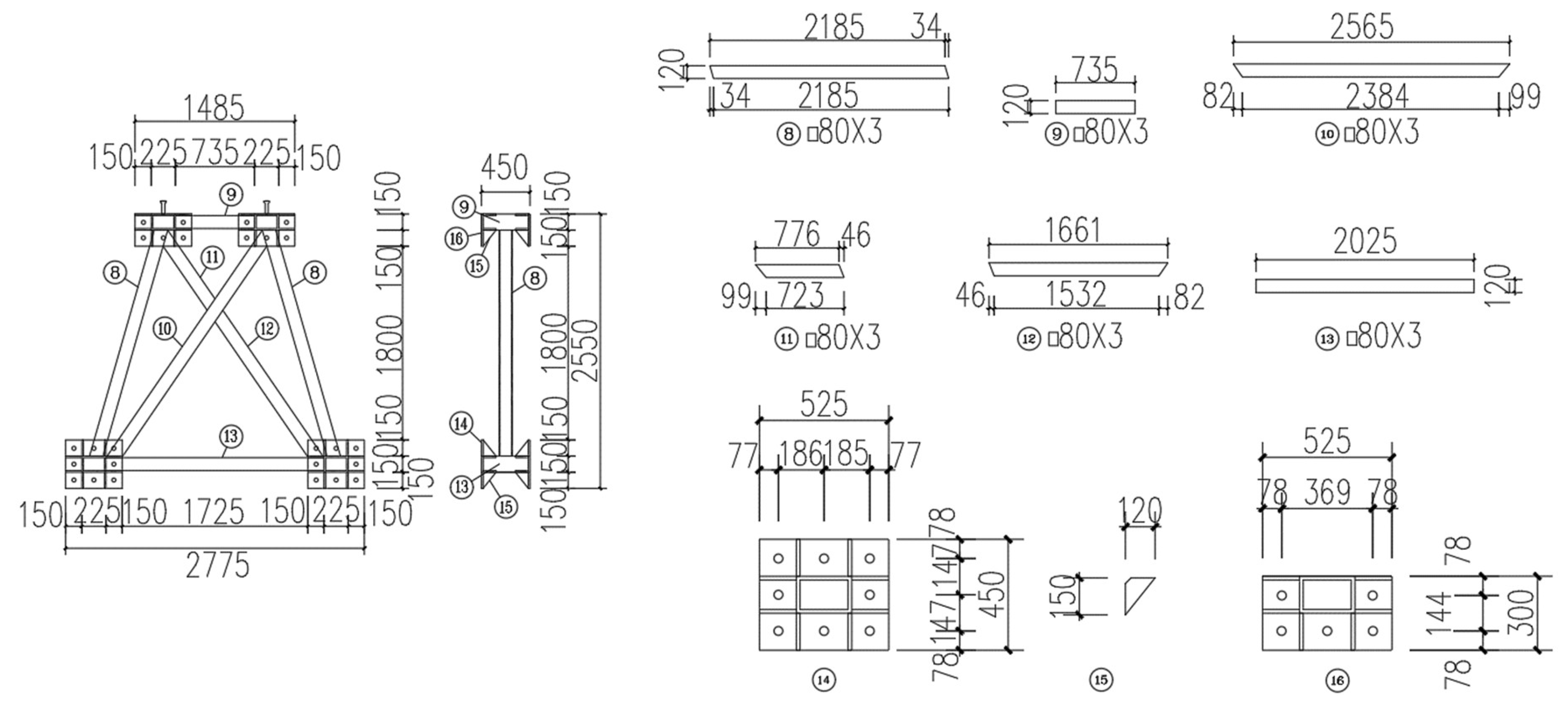
Figure 15.
Dimension drawing of the upper and lower chord plane (Unit: mm): (a) the upper chord plane; (b) the lower chord plane.
Figure 15.
Dimension drawing of the upper and lower chord plane (Unit: mm): (a) the upper chord plane; (b) the lower chord plane.
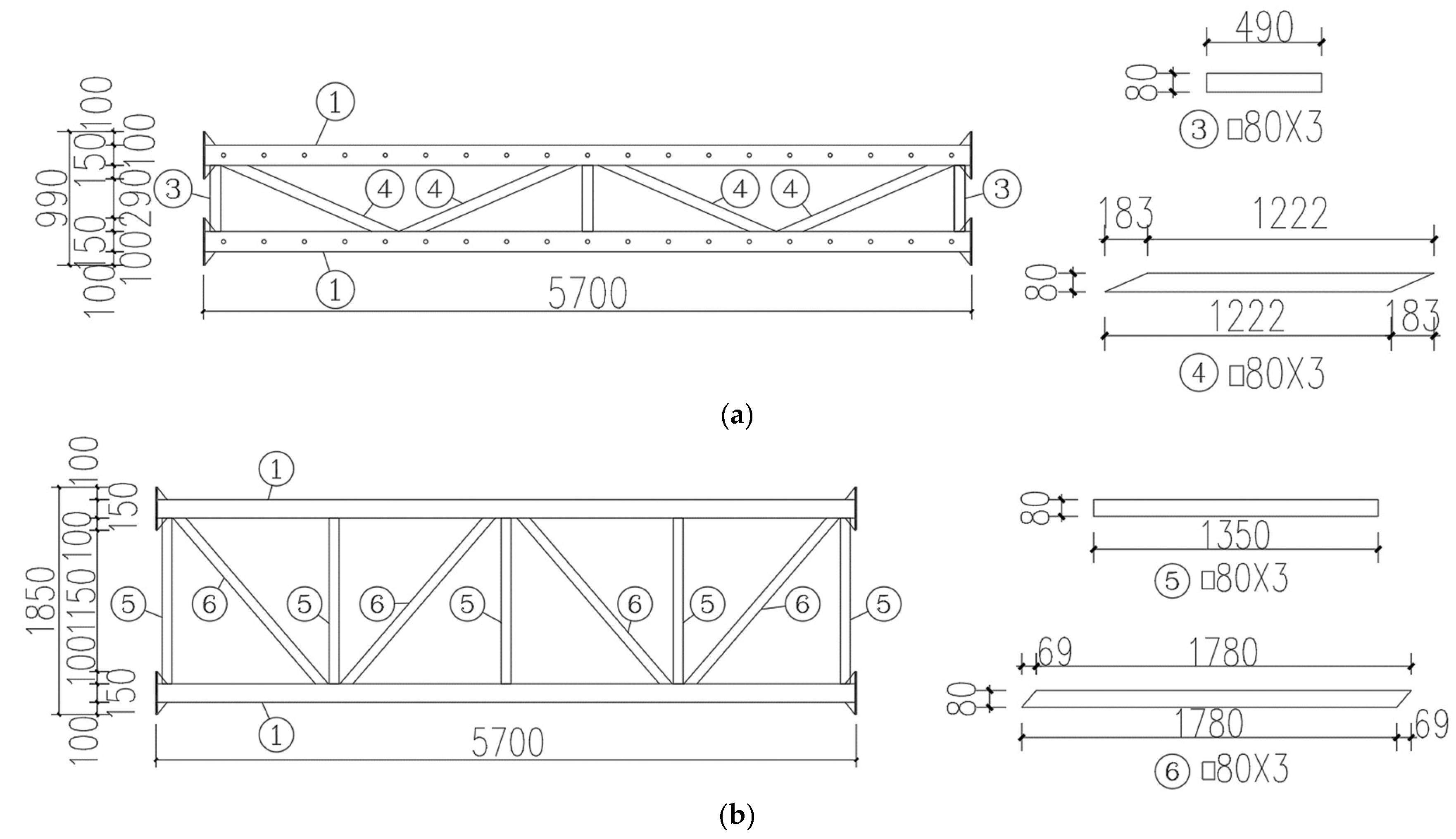
Figure 16.
Dimension drawing of the chevron-shaped UHPC cover plate (Unit: mm).
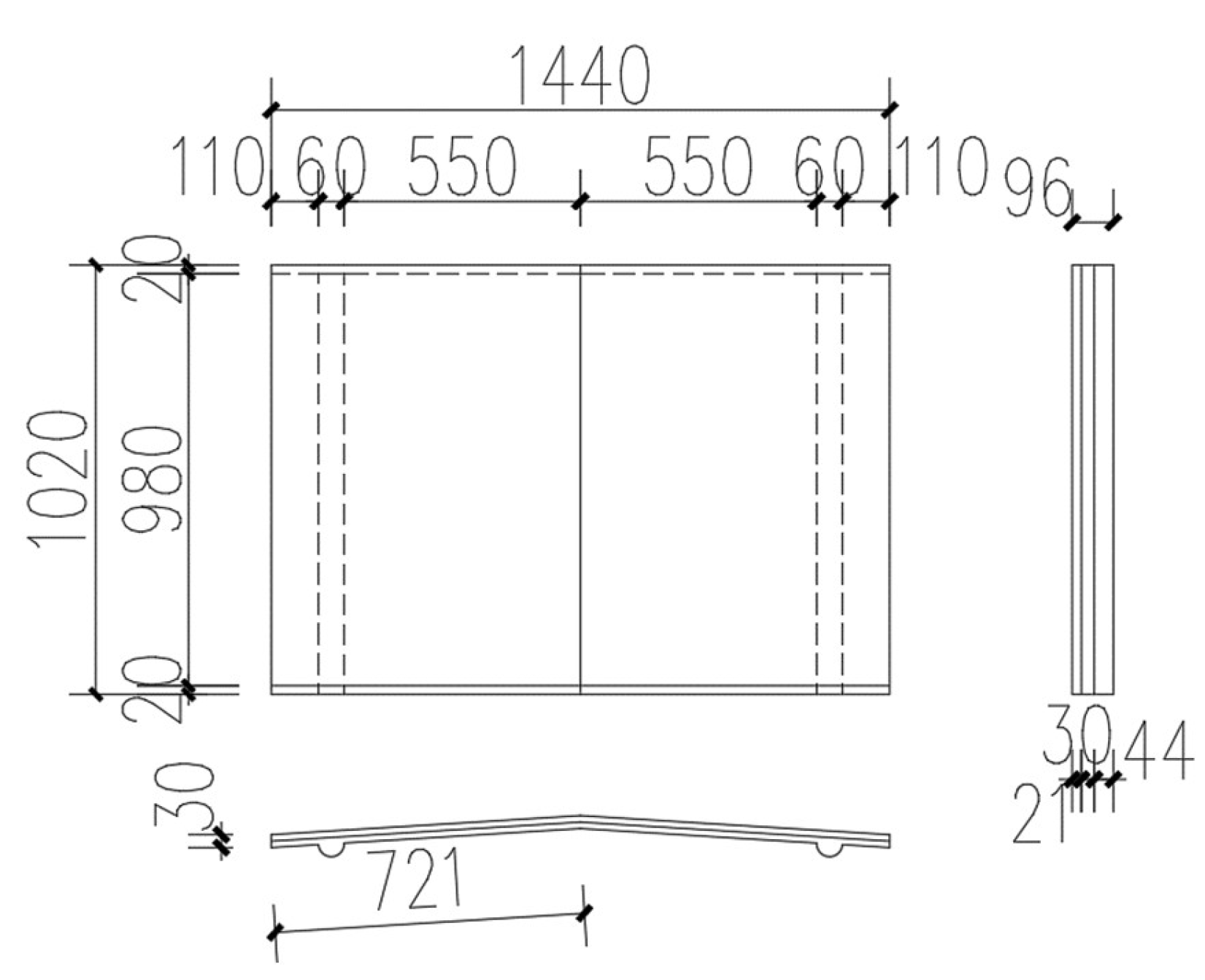
Figure 17.
Dimension drawing of the UHPC cable duct (Unit: mm).
Figure 18.
FE model of the 36-m span modular assembled cable bridge (Only the half-span model is presented here to illustrate the details).
Figure 18.
FE model of the 36-m span modular assembled cable bridge (Only the half-span model is presented here to illustrate the details).
Figure 19.
Material constitutive models: (a) steel under compression and tension; (b) UHPC under compression; (c) UHPC under tension.
Figure 19.
Material constitutive models: (a) steel under compression and tension; (b) UHPC under compression; (c) UHPC under tension.
Figure 20.
Connector element.
Figure 21.
Stress contours of the UHPC cable duct in Case 9 (Unit: MPa): (a) maximum principal stress contour; (b) minimum principal stress contour.
Figure 21.
Stress contours of the UHPC cable duct in Case 9 (Unit: MPa): (a) maximum principal stress contour; (b) minimum principal stress contour.
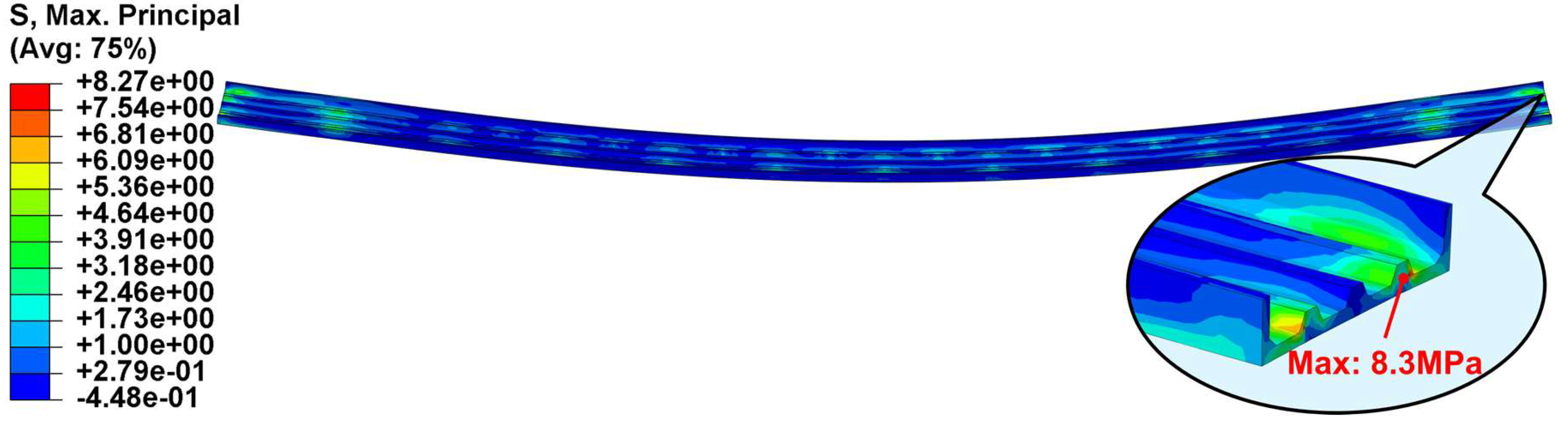
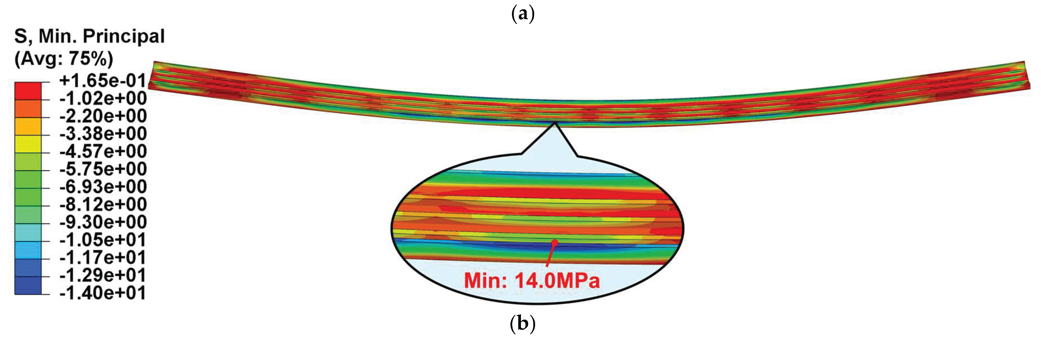
Figure 22.
Tensile damage contour of the UHPC cable duct in Case 9.
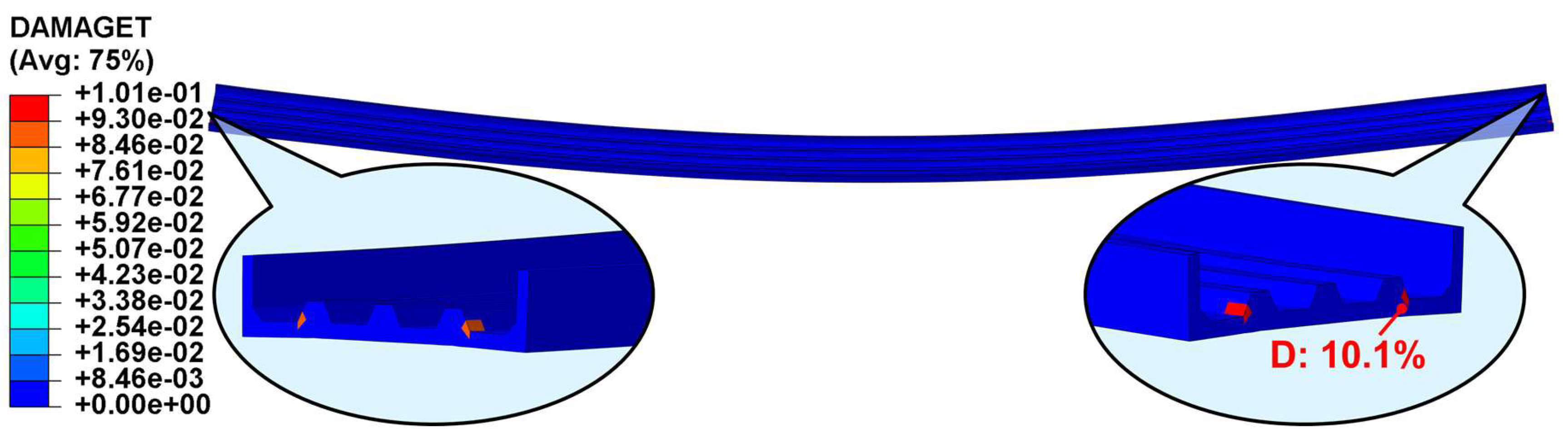
Figure 23.
Mises stress contour of the steel truss in Case 9 (Unit: MPa).
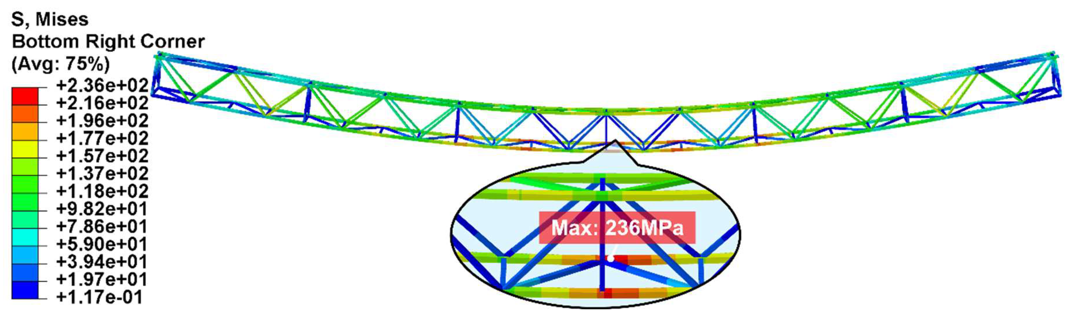
Figure 24.
Section forces contour of the steel truss in Case 9 (Unit: MPa): (a) axial force; (b) shear force in horizontal direction; (c) shear force in vertical direction.
Figure 24.
Section forces contour of the steel truss in Case 9 (Unit: MPa): (a) axial force; (b) shear force in horizontal direction; (c) shear force in vertical direction.
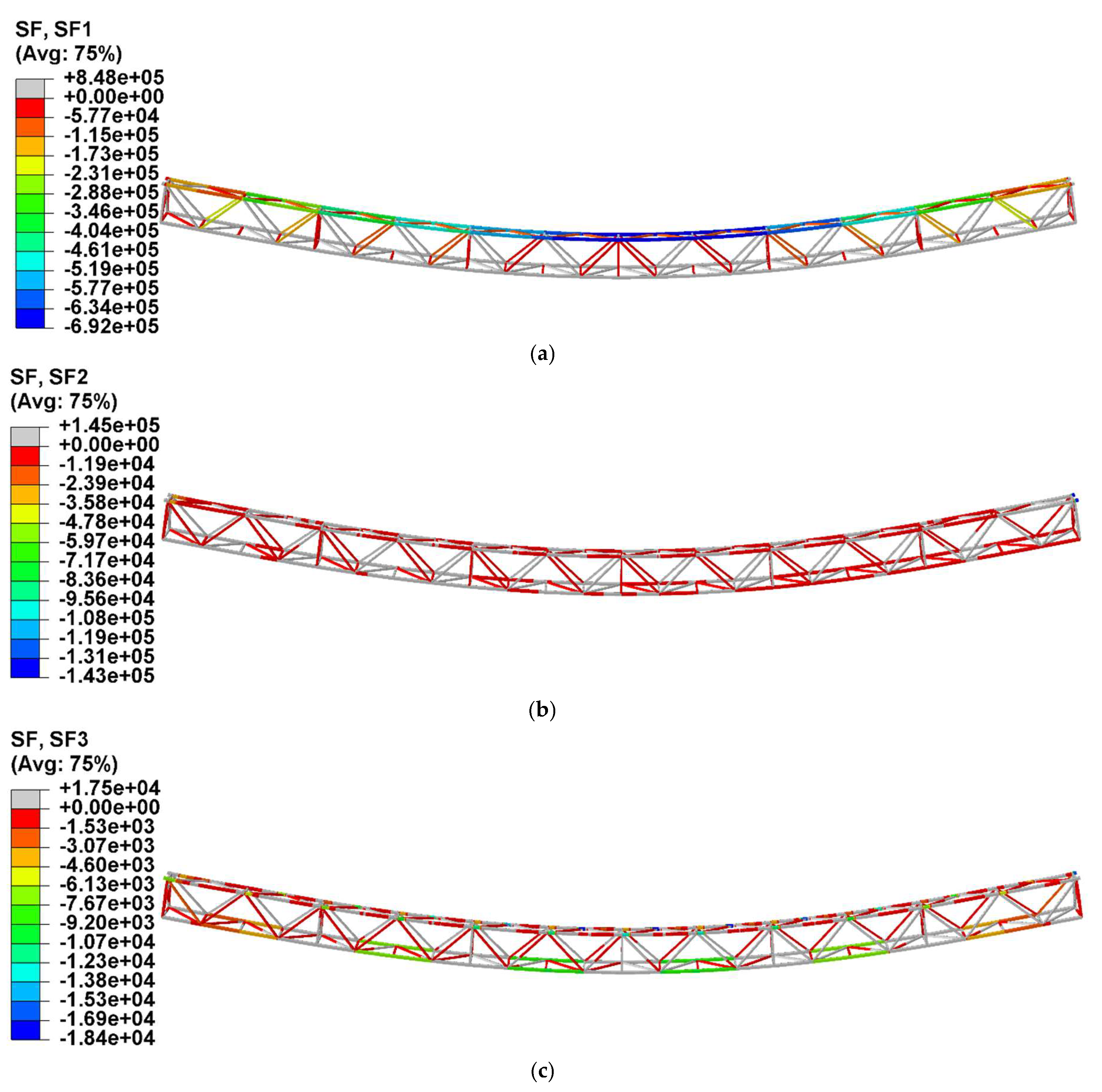
Figure 25.
Vertical displacement contour of the cable bridge in Case 9 (Unit: mm).
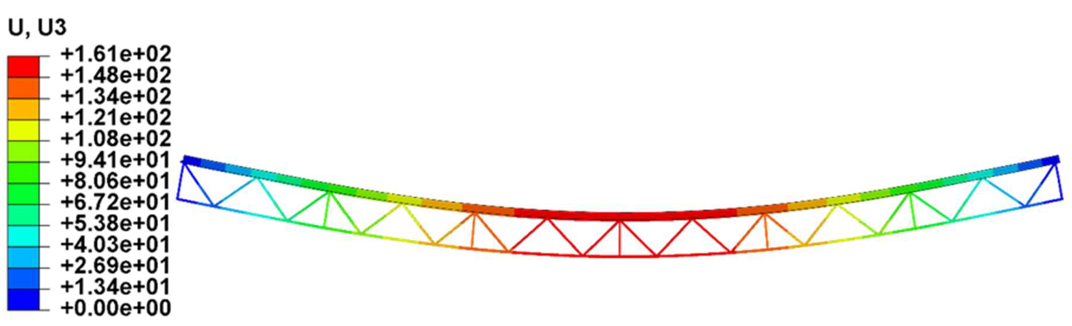
Figure 26.
Mises stress contour of the steel truss in Case 7 (Unit: MPa).
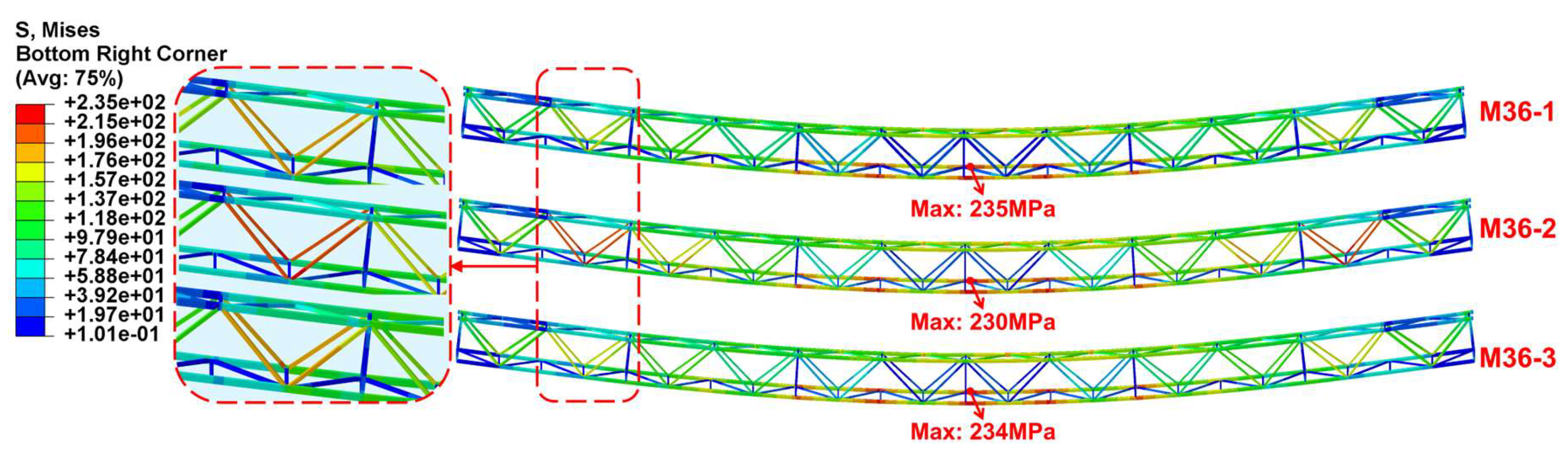

Table 1.
Mechanical properties of steel (Unit: MPa).
| Member type | Material | Yield strength | Tensile strength | Plastic strain |
|---|---|---|---|---|
| Chord | Q345 | 345 | 470 | 0.061 |
| Reinforcement | HRB400 | 400 | 600 | 0.097 |
Table 2.
Mechanical properties of UHPC (Unit: MPa).
| Material | Cubic strength | Tensile strength | Flexural strength | Young’s modulus |
|---|---|---|---|---|
| UHPC | 122 | 8 | 24 | 44.2×10³ |
Table 3.
Parameter value of CDP model.
| Dilation angle ψ | Eccentricity e | σbo/σco | K | Viscosity parameter |
|---|---|---|---|---|
| 55 | 0.1 | 2 | 0.667 | 0.005 |
Table 4.
Value of equivalent loads.
| Loads | Load distribution | Load region | Load value |
|---|---|---|---|
| Cable bridge gravity | Uniform | Whole model | 9800 mm/s2 |
| Cable gravity | Uniform | The inner bottom surface of the UHPC cable duct | 0.01 N/mm2 |
| Cover plate gravity | Uniform | The top surface of the UHPC cable duct | 0.015 N/mm2 |
| Wind load | Uniform | The outer front surface of the UHPC cable duct | 0.0005 N/mm2 |
| Wind load | Line | The front surface of the steel truss | 0.04 N/mm |
| Construction load | Uniform | The top surface of the UHPC cable duct | 0.002 N/mm2 |
| Dust load | Uniform | The top surface of the UHPC cable duct | 0.0005 N/mm2 |
| Snow load | Uniform | The top surface of the UHPC cable duct | 0.0003 N/mm2 |
| Lifting load | Uniform | Whole model | 10780 mm/s2 |
| Maintenance load | Uniform | The top surface of the UHPC cable duct | 0.002 N/mm2 |
Table 5.
Load combination cases.
|
Load type |
Dead load | Live load | |||||||
| Cable bridge gravity | Cable gravity | Cover plate gravity | Wind load | Construction load | Dust load |
Snow load | Lifting load | Maintenance load | |
| Case 1 | √ | √ | |||||||
| Case 2 | √ | √ | |||||||
| Case 3 | √ | √ | √ | ||||||
| Case 4 | √ | √ | √ | √ | |||||
| Case 5 | √ | √ | √ | ||||||
| Case 6 | √ | √ | √ | √ | |||||
| Case 7 | √ | √ | √ | √ | |||||
| Case 8 | √ | √ | √ | √ | |||||
| Case 9 | √ | √ | √ | √ | √ | √ | |||
| Note: Partial factors for dead and live loads are respectively 1.3 and 1.5; Combination factor is 1.0 for live loads for conservative reasons. | |||||||||
Table 6.
FE analysis results under the whole load cases.
| Load cases | Max. principal stress in concrete/MPa | Min. principal stress in concrete/MPa | Max. mises stress in steel truss/MPa | Max. VD/mm | Max. HD/mm | LS/mm |
|---|---|---|---|---|---|---|
| Case 1 | 6.8 | 9.7 | 163.6 | 110.0 | 1.3 | 7.8 |
| Case 2 | 3.7 | 6.0 | 81.3 | 45.6 | 1.5 | 1.5 |
| Case 3 | 8.1 | 11.9 | 206.0 | 141.4 | 1.2 | 10.5 |
| Case 4 | 8.3 | 13.3 | 234.9 | 163.2 | 1.1 | 12.4 |
| Case 5 | 8.3 | 13.1 | 230.5 | 159.9 | 1.1 | 12.1 |
| Case 6 | 8.3 | 13.9 | 233.8 | 159.9 | 5.1 | 12.1 |
| Case 7 | 8.3 | 13.3 | 234.9 | 163.2 | 1.1 | 12.4 |
| Case 8 | 8.3 | 13.1 | 231.6 | 160.7 | 1.1 | 12.2 |
| Case 9 | 8.3 | 14.0 | 235.6 | 161.3 | 5.1 | 12.2 |
Table 7.
Results of FE parameter analysis.
| Model number | Cross-sectional dimensions of the central diagonal webs /mm | Cross-sectional dimensions of the end diagonal webs /mm | Mass /t |
Load cases | Max. principal stress in concrete /MPa |
Min. principal stress in concrete /MPa |
Max. mises stress in steel truss /MPa | Max. VD /mm | Max. HD /mm | LS /mm |
|---|---|---|---|---|---|---|---|---|---|---|
| M36-1 | 80×80×3 | 80×80×6 | 19.48 | Case 7 | 8.3 | 13.3 | 234.9 | 163.2 | 1.1 | 12.4 |
| Case 9 | 8.3 | 14.0 | 235.6 | 161.3 | 5.1 | 12.2 | ||||
| M36-2 | 60×60×3 | 80×80×5 | 18.97 | Case 7 | 8.3 | 13.6 | 230.0 | 168.0 | 1.2 | 12.5 |
| Case 9 | 8.3 | 14.4 | 230.5 | 166.0 | 5.3 | 12.4 | ||||
| M36-3 | 60×60×4 | 80×80×5 | 19.39 | Case 7 | 8.3 | 13.3 | 234.4 | 164.5 | 1.1 | 12.5 |
| Case 9 | 8.3 | 14.1 | 235.1 | 162.6 | 5.1 | 12.3 | ||||
| M36-4 | 80×80×3 | 80×80×5 | 18.23 | Case 7 | 8.3 | 13.3 | 234.9 | 163.9 | 1.1 | 12.4 |
| Case 9 | 8.3 | 14.0 | 235.6 | 162.0 | 5.1 | 12.3 | ||||
| M30-1 | 80×80×3 | 80×80×6 | 16.2 | Case 7 | 8.2 | 10.2 | 159.0 | 80.2 | 0.8 | 4.1 |
| Case 9 | 8.2 | 10.7 | 159.3 | 79.1 | 2.6 | 4.1 | ||||
| Note: M36-1 model is the initial FE model of the 36-m assemble cable bridge. | ||||||||||
Disclaimer/Publisher’s Note: The statements, opinions and data contained in all publications are solely those of the individual author(s) and contributor(s) and not of MDPI and/or the editor(s). MDPI and/or the editor(s) disclaim responsibility for any injury to people or property resulting from any ideas, methods, instructions or products referred to in the content. |
© 2026 by the authors. Licensee MDPI, Basel, Switzerland. This article is an open access article distributed under the terms and conditions of the Creative Commons Attribution (CC BY) license (http://creativecommons.org/licenses/by/4.0/).
Copyright: This open access article is published under a Creative Commons CC BY 4.0 license, which permit the free download, distribution, and reuse, provided that the author and preprint are cited in any reuse.


